JP5696678B2 - Image forming apparatus - Google Patents
Image forming apparatus Download PDFInfo
- Publication number
- JP5696678B2 JP5696678B2 JP2012060062A JP2012060062A JP5696678B2 JP 5696678 B2 JP5696678 B2 JP 5696678B2 JP 2012060062 A JP2012060062 A JP 2012060062A JP 2012060062 A JP2012060062 A JP 2012060062A JP 5696678 B2 JP5696678 B2 JP 5696678B2
- Authority
- JP
- Japan
- Prior art keywords
- toner
- bias
- voltage
- component
- transfer
- Prior art date
- Legal status (The legal status is an assumption and is not a legal conclusion. Google has not performed a legal analysis and makes no representation as to the accuracy of the status listed.)
- Active
Links
Images


Classifications
-
- G—PHYSICS
- G03—PHOTOGRAPHY; CINEMATOGRAPHY; ANALOGOUS TECHNIQUES USING WAVES OTHER THAN OPTICAL WAVES; ELECTROGRAPHY; HOLOGRAPHY
- G03G—ELECTROGRAPHY; ELECTROPHOTOGRAPHY; MAGNETOGRAPHY
- G03G15/00—Apparatus for electrographic processes using a charge pattern
- G03G15/14—Apparatus for electrographic processes using a charge pattern for transferring a pattern to a second base
- G03G15/16—Apparatus for electrographic processes using a charge pattern for transferring a pattern to a second base of a toner pattern, e.g. a powder pattern, e.g. magnetic transfer
- G03G15/1665—Apparatus for electrographic processes using a charge pattern for transferring a pattern to a second base of a toner pattern, e.g. a powder pattern, e.g. magnetic transfer by introducing the second base in the nip formed by the recording member and at least one transfer member, e.g. in combination with bias or heat
-
- G—PHYSICS
- G03—PHOTOGRAPHY; CINEMATOGRAPHY; ANALOGOUS TECHNIQUES USING WAVES OTHER THAN OPTICAL WAVES; ELECTROGRAPHY; HOLOGRAPHY
- G03G—ELECTROGRAPHY; ELECTROPHOTOGRAPHY; MAGNETOGRAPHY
- G03G15/00—Apparatus for electrographic processes using a charge pattern
- G03G15/01—Apparatus for electrographic processes using a charge pattern for producing multicoloured copies
- G03G15/0142—Structure of complete machines
- G03G15/0178—Structure of complete machines using more than one reusable electrographic recording member, e.g. one for every monocolour image
- G03G15/0189—Structure of complete machines using more than one reusable electrographic recording member, e.g. one for every monocolour image primary transfer to an intermediate transfer belt
-
- G—PHYSICS
- G03—PHOTOGRAPHY; CINEMATOGRAPHY; ANALOGOUS TECHNIQUES USING WAVES OTHER THAN OPTICAL WAVES; ELECTROGRAPHY; HOLOGRAPHY
- G03G—ELECTROGRAPHY; ELECTROPHOTOGRAPHY; MAGNETOGRAPHY
- G03G15/00—Apparatus for electrographic processes using a charge pattern
- G03G15/02—Apparatus for electrographic processes using a charge pattern for laying down a uniform charge, e.g. for sensitising; Corona discharge devices
- G03G15/0266—Arrangements for controlling the amount of charge
-
- G—PHYSICS
- G03—PHOTOGRAPHY; CINEMATOGRAPHY; ANALOGOUS TECHNIQUES USING WAVES OTHER THAN OPTICAL WAVES; ELECTROGRAPHY; HOLOGRAPHY
- G03G—ELECTROGRAPHY; ELECTROPHOTOGRAPHY; MAGNETOGRAPHY
- G03G2215/00—Apparatus for electrophotographic processes
- G03G2215/01—Apparatus for electrophotographic processes for producing multicoloured copies
- G03G2215/0103—Plural electrographic recording members
- G03G2215/0119—Linear arrangement adjacent plural transfer points
- G03G2215/0122—Linear arrangement adjacent plural transfer points primary transfer to an intermediate transfer belt
- G03G2215/0125—Linear arrangement adjacent plural transfer points primary transfer to an intermediate transfer belt the linear arrangement being horizontal or slanted
- G03G2215/0129—Linear arrangement adjacent plural transfer points primary transfer to an intermediate transfer belt the linear arrangement being horizontal or slanted horizontal medium transport path at the secondary transfer
Landscapes
- Physics & Mathematics (AREA)
- General Physics & Mathematics (AREA)
- Engineering & Computer Science (AREA)
- Plasma & Fusion (AREA)
- Electrostatic Charge, Transfer And Separation In Electrography (AREA)
- Color Electrophotography (AREA)
Description
本発明は、電子写真方式を用いた複写機、プリンタ等の画像形成装置に関するものである。 The present invention relates to an image forming apparatus such as a copying machine or a printer using an electrophotographic system.
電子写真方式の画像形成装置においては、あらかじめ一様に帯電された感光体等の像担持体上に光学的な画像情報を形成することによって得た帯電潜像を、現像装置からのトナーによって可視化し、この可視像を転写紙等の記録媒体上に直接又は中間転写ベルト等の中間転写体を介して転写し、記録媒体上に定着することによって画像形成を行っている。 In an electrophotographic image forming apparatus, a charged latent image obtained by forming optical image information on an image carrier such as a uniformly charged photoreceptor is visualized by toner from a developing device. The visible image is transferred directly onto a recording medium such as transfer paper or via an intermediate transfer member such as an intermediate transfer belt, and fixed on the recording medium to form an image.
このような画像形成装置において、従来、転写手段に直流バイアスを印加して画像(トナー像)を記録媒体に転写させるDC転写方式が広く採用されている。また、近年では、直流電圧に交流電圧を重畳した重畳バイアス(交流バイアスと呼ばれることもある)を用いるAC転写方式(以下、本願では、転写バイアスとして直流電圧に交流電圧を重畳した重畳バイアスを用いた転写をAC転写と記す)を採用したものも現れている。AC転写方式は、表面に凹凸が存在しているような記録媒体(用紙)への転写性において、DC転写方式よりも優れるとされ、転写率の向上や中抜けなどの異常画像を改善できることが知られている。 In such an image forming apparatus, conventionally, a DC transfer method in which a DC bias is applied to a transfer unit to transfer an image (toner image) onto a recording medium has been widely adopted. In recent years, an AC transfer method using a superimposed bias in which an AC voltage is superimposed on a DC voltage (sometimes referred to as an AC bias) (hereinafter, in this application, a superimposed bias in which an AC voltage is superimposed on a DC voltage is used as a transfer bias). In some cases, the transfer was referred to as AC transfer). The AC transfer method is superior to the DC transfer method in terms of transferability to a recording medium (paper) having irregularities on the surface, and can improve abnormal images such as an increase in transfer rate and voids. Are known.
しかしながら、AC転写方式を用いる場合に、モノクロ画像を形成するモノクロモード時と、多色画像又はフルカラー画像を形成するカラーモード時とで、同じ転写バイアスを印加したのでは、最適な転写姓を得ることはできない。 However, when the AC transfer method is used, the same transfer bias is applied in the monochrome mode for forming a monochrome image and in the color mode for forming a multi-color image or a full-color image, thereby obtaining an optimal transfer last name. It is not possible.
特開2004−117920号公報(特許文献1)には、カラーモードによって、転写バイアスとして印加する直流電圧の値を変更することが提案されている。DC転写方式を用いる上記特許文献1においては、トナーの載り量差に起因する転写不良を防止するために、モノクロ画像を形成する場合の転写電圧よりもカラー画像を形成する場合の転写電圧を大きくしている。
Japanese Patent Laid-Open No. 2004-117920 (Patent Document 1) proposes changing the value of a DC voltage applied as a transfer bias depending on a color mode. In
ところが、AC転写方式では、転写電圧に比例して転写性が向上するわけではなく、単純に転写電圧を大きくしても、トナーの載り量の多いカラー画像を良好に転写することができないという問題があった。 However, in the AC transfer system, the transferability does not improve in proportion to the transfer voltage, and even if the transfer voltage is simply increased, a color image with a large amount of toner cannot be transferred satisfactorily. was there.
本発明は、転写バイアスとして直流電圧に交流電圧を重畳して印加可能に構成された従来の画像形成装置における上述の問題を解決し、カラーモードに関わらず良好な転写性を得ることのできる画像形成装置を提供することを課題とする。 The present invention solves the above-described problems in a conventional image forming apparatus configured to be able to apply an AC voltage superimposed on a DC voltage as a transfer bias, and an image capable of obtaining good transferability regardless of the color mode. It is an object to provide a forming apparatus.
前記の課題は、本発明により、極性が交互に切替わるバイアスを印加して、所定極性に帯電したトナー像を像担持体から記録媒体へ転写する画像形成装置において、複数色のトナーからなるトナー像を転写するカラーモードと、単色のトナーからなるトナー像を転写する単色モードと、を有し、前記バイアスは、記録媒体から前記像担持体へとトナーを戻す極性のピーク電圧を有し、前記カラーモード時の前記ピーク電圧の絶対値は、前記単色モード時の前記ピーク電圧の絶対値以上であることにより解決される。
また、前記の課題は、本発明により、バイアスを印加して、所定極性に帯電したトナー像を像担持体から記録媒体へ転写する画像形成装置において、複数色のトナーからなるトナー像を転写するカラーモードと、単色のトナーからなるトナー像を転写する単色モードと、を有し、前記バイアスは、前記像担持体から記録媒体へとトナーを移動させる方向の電界と、記録媒体から前記像担持体へとトナーを戻す方向の戻し電界と、を交互に形成し、前記カラーモード時の前記戻し電界のピークの絶対値は、前記単色モード時の前記戻し電界のピークの絶対値以上であることにより解決される。
In the image forming apparatus for transferring a toner image charged to a predetermined polarity from the image carrier to a recording medium by applying a bias whose polarity is alternately switched according to the present invention, the toner comprising a plurality of color toners is provided. A color mode for transferring an image and a single color mode for transferring a toner image composed of a single color toner, and the bias has a peak voltage of polarity for returning the toner from the recording medium to the image carrier , The absolute value of the peak voltage in the color mode is solved by being equal to or greater than the absolute value of the peak voltage in the monochrome mode .
Another object of the present invention is to transfer a toner image composed of a plurality of color toners in an image forming apparatus that applies a bias and transfers a toner image charged to a predetermined polarity from an image carrier to a recording medium. A color mode and a single color mode for transferring a toner image composed of a single color toner, wherein the bias is an electric field in a direction of moving the toner from the image carrier to the recording medium, and the image bearing from the recording medium. A return electric field in a direction to return the toner to the body is alternately formed, and the absolute value of the peak of the return electric field in the color mode is equal to or greater than the absolute value of the peak of the return electric field in the monochrome mode. It is solved by.
本発明の画像形成装置によれば、トナー載り量の多いカラーモード時においても、良好な転写性を得ることができ、かつ、凹凸の大きな用紙に対しても用紙凹部への良好な転写性を得ることができる。 According to the image forming apparatus of the present invention, even in many-color mode of preparative toner bearing amount, it is possible to obtain good transfer properties, and good transferability onto paper recess even for large sheets of irregularities Can be obtained.
以下、本発明の実施の形態を図面に基づいて説明する。
図1は、本発明が適用される画像形成装置の一例である中間転写方式のカラー画像形成装置(以下、単にプリンタと呼ぶ)の概略を示す断面構成図である。この図に示すプリンタは、中間転写体としての無端状ベルト(中間転写ベルト51)を有しており、その中間転写ベルト51の上部走行辺に沿って、イエロー(Y),マゼンタ(M),シアン(C),ブラック(K)の各色トナー画像を形成するための4つの画像形成ユニット1Y,1M,1C,1Kが並設され、タンデム作像部を構成している。
Hereinafter, embodiments of the present invention will be described with reference to the drawings.
FIG. 1 is a cross-sectional configuration diagram showing an outline of an intermediate transfer type color image forming apparatus (hereinafter simply referred to as a printer) which is an example of an image forming apparatus to which the present invention is applied. The printer shown in this figure has an endless belt (intermediate transfer belt 51) as an intermediate transfer body, and along the upper running side of the
各画像形成ユニット1Y,1M,1C,1Kは扱うトナーの色が異なるのみで構成は同一であるため、図2を参照して一つの画像形成ユニットについてのみ説明する。図2に示すように、画像形成ユニットは、像担持体としての感光体ドラム11、感光体ドラム11の表面を帯電ローラによって帯電する帯電装置21、感光体ドラム11上の潜像を可視化する現像装置31、感光体ドラム11から中間転写ベルト51にトナー像を転写させる一次転写手段としての転写ローラ55、感光体ドラム11表面をクリーニングするクリーニング装置41等を備えている。本実施形態では、各画像形成ユニット1Y,1M,1C,1Kは、プリンタ本体に対して脱着可能に設けられている。
Since the
本例の感光体11は、ドラム基体の表面上に有機感光層が形成された外径60mm程度のドラム形状のものであって、図示しない駆動手段によって図中時計回りに回転駆動される。帯電装置21は、帯電バイアスが印加される帯電ローラを感光体ドラム11に接触あるいは近接させながら、帯電ローラと感光体11との間に放電を発生させることで、感光体表面を一様帯電せしめる。本実施形態では、トナーの正規帯電極性と同じマイナス極性に一様帯電せしめる。帯電バイアスとしては、直流電圧に交流電圧を重畳したものを採用している。帯電ローラを用いる方式に変えて、帯電チャージャによる方式を採用しても良い。
The
現像装置31は、トナーとキャリアからなる2成分現像剤が収容される収容容器内に、現像剤担持体としての現像スリーブ31a及び現像剤を攪拌しながら搬送する攪拌部材としての2本のスクリュー部材31b,31cを備えている。なお、1成分現像剤を用いる現像装置を採用することも可能である。
The developing
クリーニング装置41は、クリーニングブレード41aと、クリーニングブラシ41bを備えている。クリーニングブレード41aは、感光体ドラム11の回転方向に対してカウンタ方向から感光体ドラム11と当接している状態で、クリーニングブラシ41bは感光体ドラム11と逆方向に回転しながら接触している状態で感光体ドラム11表面をクリーニングする。
The
図1に戻り、画像形成ユニット1Y,1M,1C,1Kの上方には、潜像書込手段たる光書込ユニット80が配設されている。この光書込ユニット80は、パーソナルコンピュータ等の外部機器から送られてくる画像情報に基づいてレーザーダイオードから発したレーザー光により、感光体11Y,11M,11C,11Kを光走査する。この光走査により、感光体11Y,11M,11C,11K上にY,M,C,K用の静電潜像が形成される。具体的には、感光体11の一様帯電した表面の全域のうち、レーザー光が照射された箇所は、電位を減衰せしめる。これにより、レーザー照射箇所の電位が、それ以外の箇所(地肌部)の電位よりも小さい静電潜像となる。なお、光書込ユニット80は、光源から発したレーザー光Lを、図示しないポリゴンモータによって回転駆動したポリゴンミラーで主走査方向に偏光せしめながら、複数の光学レンズやミラーを介して感光体に照射するものである。LEDアレイの複数のLEDから発したLED光によって光書込を行うものを採用してもよい。
Returning to FIG. 1, an
画像形成ユニット1Y,1M,1C,1Kの下方には、無端状の中間転写ベルト51を張架しながら図中反時計回り方向に無端移動せしめる転写装置としての転写ユニット50が配設されている。転写ユニット50は、像担持体たる中間転写ベルト51の他に、駆動ローラ52、二次転写裏面ローラ53、クリーニングバックアップローラ54、4つの一次転写ローラ55、ニップ形成ローラ56、ベルトクリーニング装置57、電位センサ58などを有している。
Below the
中間転写ベルト51は、そのループ内側に配設された駆動ローラ52、二次転写裏面ローラ53、クリーニングバックアップローラ54、及び4つの一次転写ローラ55によって張架されており、図示しない駆動手段によって図中反時計回り方向に回転駆動される駆動ローラ52の回転力により、同方向に無端移動せしめられる。中間転写ベルト51としては、次のような特性を有するものを用いている。即ち、厚みは20[μm]〜200[μm]、好ましくは60[μm]程度である。表面抵抗率は9.0〜13.0[LogΩ/□]、好ましくは10.0〜12.0[LogΩ/□]である(HRSプローブにて、印加電圧500V、10sec値の条件で測定)。また、体積抵抗率は6.0〜13[LogΩ・cm]、好ましくは7.5〜12.5[LogΩ・cm]、より好ましくは約9[LogΩ・cm]程度である(HRSプローブにて、印加電圧100V、10sec値の条件で測定)。また、材料は、カーボン分散ポリイミド樹脂からなる。
The
4つの一次転写ローラ55は、無端移動せしめられる中間転写ベルト51を感光体11(Y,M,C,K)との間に挟み込んでいる。これにより、中間転写ベルト51のおもて面と、感光体11(Y,M,C,K)とが当接するY,M,C,K用の一次転写ニップが形成されている。一次転写ローラ55には、図示しない転写バイアス電源によってそれぞれ一次転写バイアスが印加されている。これにより、感光体11(Y,M,C,K)上の各色トナー像と、各色一次転写ローラ55との間に転写電界が形成され、転写電界やニップ圧の作用により、感光体11上から中間転写ベルト51上にトナー像が一次転写される。Yトナー像上にM,C,Kトナー像が、順次重ね合わせて一次転写されることにより、中間転写ベルト51上には4色重ね合わせトナー像が形成される。
The four
モノクロ画像を形成する場合には、転写ユニット50におけるY,M,C用の一次転写ローラ55Y,M,Cを支持している図示しない支持板を移動せしめて、一次転写ローラ55Y,M,Cを、感光体11Y,M,Cから遠ざける。これにより、中間転写ベルト51のおもて面を感光体11Y,M,Cから引き離して、中間転写ベルト51をK用の感光体11Kだけに当接させる。この状態で、4つの画像形成ユニット1Y,M,C,Kのうち、K用の画像形成ユニット1Kだけを駆動して、Kトナー像を感光体11K上に形成する。
When a monochrome image is formed, a support plate (not shown) supporting the primary transfer rollers 55Y, 55M, 55C for Y, M, C in the
一次転写ローラ55は、金属製の芯金と、これの表面上に固定された導電性のスポンジ層とを具備している弾性ローラからなり、本例では次のような特性を有している。ローラ外形は16[mm]で、心金の径は10[mm]である。5[N]/片側の加重を加え、転写ローラ軸に1[kV]のバイアスを印加し、1分の測定間にローラを1回転させながら抵抗値を測定し、その平均値を体積抵抗とする回転測定法により、オームの法則(R=V/I)に基づいて算出したスポンジ層の抵抗Rは、1e6Ω〜1e9Ω、好ましくは約3E7Ωである。このような一次転写ローラ55に対して、一次転写バイアスを定電流制御で印加する。なお、転写ローラに代えて、転写チャージャーや転写ブラシなどを採用してもよい。
The
転写ユニット50のニップ形成ローラ56は、中間転写ベルト51のループ外側に配設されており、ループ内側の二次転写裏面ローラ53との間に中間転写ベルト51を挟み込んでいる。これにより、中間転写ベルト51のおもて面と、ニップ形成ローラ56とが当接する二次転写ニップが形成されている。ニップ形成ローラ56は接地されているのに対し、二次転写裏面ローラ53には、二次転写バイアス電源200によって二次転写バイアスが印加される。これにより、二次転写裏面ローラ53とニップ形成ローラ56との間に、トナーを二次転写裏面ローラ53側からニップ形成ローラ56側に向けて静電移動させる二次転写電界が形成される。
The nip forming
転写ユニット50の下方には、記録紙Pを複数枚重ねた紙束の状態で収容している給紙カセット100が配設されている。この給紙カセット100は、紙束の一番上の記録紙Pに給紙ローラ101を当接させており、これを所定のタイミングで回転駆動させることで、その記録紙Pを給紙路に向けて送り出す。給紙路の末端付近には、レジストローラ対102が配設されている。このレジストローラ対102は、給紙カセット100から送り出された記録紙Pをローラ間に挟み込むとすぐに両ローラの回転を停止させる。そして、挟み込んだ記録紙Pを二次転写ニップ内で中間転写ベルト51上のトナー像に同期させ得るタイミングで回転駆動を再開して、記録紙Pを二次転写ニップに向けて送り出す。二次転写ニップで記録紙Pに密着せしめられた中間転写ベルト51上のトナー像は、二次転写電界やニップ圧の作用によって記録紙P上に一括二次転写される。このようにして表面にフルカラートナー像またはモノクロトナー像が形成された記録紙Pは、二次転写ニップを通過すると、ニップ形成ローラ56や中間転写ベルト51から曲率分離する。
Below the
二次転写裏面ローラ53(二次転写ローラ)は、ステンレスやアルミニウム等からなる芯金に抵抗層を積層したものである。抵抗層は、ポリカーボネート,フッ素系ゴム,シリコン系ゴム等にカーボンや金属錯体等の導電粒子を分散させたもの、あるいはNBRやEPDM等のゴム、NBR/ECO共重合のゴム、ポリウレタンの半導電性ゴム等よりなる。上記した一次転写ローラの場合と同様の回転測定法により測定した二次転写裏面ローラ53の体積抵抗は6.0〜8.0[LogΩ]、好ましくは7.0〜8.0[LogΩ]である。また、硬度20度〜50度の発泡タイプでも、ゴム硬度30度〜60度のゴムタイプでもよいが、中間転写ベルト51を介してニップ形成ローラ56と接触するので、小さな接触圧力でも非接触部分が生じないスポンジタイプが望ましい。中間転写ベルト51と二次転写裏面ローラ53の接触圧力が大きいほど、文字や細線の中抜けが生じ易いので、これを防止するためである。
The secondary transfer back roller 53 (secondary transfer roller) is formed by laminating a resistance layer on a metal core made of stainless steel, aluminum, or the like. The resistance layer is made by dispersing conductive particles such as carbon and metal complexes in polycarbonate, fluorine rubber, silicon rubber, or the like, or rubber such as NBR or EPDM, rubber of NBR / ECO copolymer, polyurethane semiconductive Made of rubber. The volume resistance of the secondary transfer back
また、ニップ形成ローラ56(対向ローラ)は、ステンレスやアルミニウム等からなる芯金上に導電性ゴム等からなる抵抗層と表層を積層して形成してある。本例では、ローラの外径は20[mm]、芯金は直径16[mm]のステンレスである。抵抗層はNBR/ECOの共重合体よりなる硬度40〜60度[JIS−A]のゴムである。表層は、含フッ素ウレタンエラストマーからなり、その厚みは8〜24[μm]が望ましい。その理由としては、ローラの表層は塗装工程により製造されることが多いので、表層の厚みが8μm以下では、塗布ムラによる抵抗ムラの影響が大きく、抵抗の低い箇所でリークが発生する可能性があり好ましくない。また、ローラ表面にシワが生じて、表層がひび割れるという問題も生じ易い。一方、表層の厚みが24μm以上に厚くなると抵抗が高くなり、体積抵抗率が高い場合には二次転写裏面ローラ53の芯金に定電流を印加したときの電圧が上昇することがあり、定電流電源の電圧可変範囲を超えるので目標の電流以下の電流になったり、電圧可変範囲が十分高い範囲の場合には定電流電源から二次転写裏面ローラ芯金までの高圧経路や二次転写裏面ローラ芯金が高電圧になることによるリークが発生し易くなる。また、ニップ形成ローラ56の表層の厚みが24μm以上に厚いと硬度が高くなり、記録媒体(紙等)や中間転写ベルトとの密着性が悪くなるという問題もある。ニップ形成ローラ56の表面抵抗は106.5[Ω]以上であり、ニップ形成ローラ56の表層の体積抵抗は6.0〜12.0[LogΩ]である。あるいはSUSなどの金属ローラを使用する場合の好ましい体積抵抗は4.0[LogΩ]である。体積抵抗の測定方法は、上記した回転測定法による。
The nip forming roller 56 (opposing roller) is formed by laminating a resistance layer and a surface layer made of conductive rubber or the like on a cored bar made of stainless steel or aluminum. In this example, the outer diameter of the roller is 20 [mm], and the core metal is stainless steel having a diameter of 16 [mm]. The resistance layer is a rubber having a hardness of 40 to 60 degrees [JIS-A] made of an NBR / ECO copolymer. The surface layer is made of a fluorine-containing urethane elastomer, and the thickness is desirably 8 to 24 [μm]. The reason for this is that the roller surface layer is often manufactured by a coating process. Therefore, when the surface layer thickness is 8 μm or less, there is a large influence of uneven resistance due to coating unevenness, and there is a possibility that leakage will occur at a location with low resistance. There is not preferable. In addition, wrinkles are generated on the roller surface and the surface layer is liable to crack. On the other hand, when the thickness of the surface layer is increased to 24 μm or more, the resistance increases, and when the volume resistivity is high, the voltage when a constant current is applied to the core of the secondary transfer back
電位センサ58は、中間転写ベルト51のループ外側に配設されている。そして、中間転写ベルト51の周方向における全域のうち、接地された駆動ローラ52に対する掛け回し箇所に対して、約4[mm]の間隙を介して対向している。そして、中間転写ベルト51上に一次転写されたトナー像が自らとの対向位置に進入した際に、そのトナー像の表面電位を測定する。なお、電位センサ58としては、TDK(株)社製のEFS−22Dを用いている。
The
二次転写ニップの図中右側方には、定着装置90が配設されている。この定着装置90は、ハロゲンランプ等の発熱源を内包する定着ローラ91と、これに所定の圧力で当接しながら回転する加圧ローラ92とによって定着ニップを形成している。定着装置90内に送り込まれた記録紙Pは、その未定着トナー像担持面を定着ローラ91に密着させる姿勢で、定着ニップに挟まれる。そして、加熱や加圧の影響によってトナー像中のトナーが軟化さしめられて、フルカラー画像が定着せしめられる。定着装置90内から排出された記録紙Pは、定着後搬送路を経由した後、機外へと排出される。
A fixing
本実施形態のプリンタが備える二次転写バイアス出力手段としての二次転写バイアス電源200は、直流電源と交流電源とを有しており、二次転写バイアスとして、直流電圧に交流電圧を重畳せしめたもの(重畳バイアス)を出力することができる。二次転写バイアス電源200の出力端子は、二次転写裏面ローラ53の芯金に接続されている。該ローラの芯金の電位は、二次転写バイアス電源200からの出力電圧値とほぼ同じ値になる。また、ニップ形成ローラ56については、その芯金を接地(アース接続)している。この場合、正規帯電極性がマイナス極性のトナーを用いるとすると、直流電圧としてトナーと同じマイナス極性のものを用いて、重畳バイアスの時間平均の電位をトナーと同じマイナス極性にする。なお、本発明において、交流電圧は、0V(ゼロボルト)をクロスするゼロクロス波形のものを用いるものとする。
A secondary transfer
ところで、二次転写部の構成は上記に限らず、二次転写裏面ローラ53を接地し、かつ、重畳バイアスをニップ形成ローラ56に印加する構成としてもよい。この場合、直流電圧としてはトナーと逆のプラス極性のものを用いて、重畳バイアスの時間平均の電位をトナーとは逆のプラス極性にする。交流電圧はゼロクロス波形のものを用いることに変わりはない。
By the way, the configuration of the secondary transfer unit is not limited to the above, and the secondary transfer back
さらに、直流電圧を、二次転写裏面ローラ53またはニップ形成ローラ56のどちらか一方に印加するとともに、交流電圧を他方のローラに印加する構成としてもよい。この場合も、直流電圧を二次転写裏面ローラ53に印加する場合は直流電圧としてトナーと同じマイナス極性のものを用い、直流電圧をニップ形成ローラ56に印加する場合は直流電圧としてトナーと逆のプラス極性のものを用いる。交流電圧はゼロクロス波形のものを用いることに変わりはない。
Furthermore, a DC voltage may be applied to either the secondary transfer back
正規帯電極性がプラス極性のトナーを用いることも可能であり、その場合は、上記説明した直流電圧の極性は、上記の場合と逆の極性のものを用いる。この場合も交流電圧はゼロクロス波形のものを用いることに変わりはない。 It is also possible to use a toner having positive charging polarity, and in this case, the polarity of the DC voltage described above is opposite to that in the above case. In this case, the AC voltage is still zero-cross waveform.
なお、本実施形態では重畳バイアスにおける交流電圧は正弦波状のものを採用しているが、矩形波状の波形のものを用いてもよい。 In the present embodiment, the AC voltage in the superimposed bias is a sinusoidal waveform, but a rectangular waveform may be used.
ここで、重畳バイアスを用いた場合の転写作用について図3を参照して説明する。
図3は、二次転写バイアス電源200から出力される重畳バイアスからなる二次転写バイアス波形の一例を示す波形図である。ここでは、二次転写バイアス(重畳バイアス)を二次転写裏面ローラ53に印加する場合で説明する。なお、電位差は絶対値として取り扱われることが一般的であるが、本稿では、極性付きの値として取り扱うものとする。より詳しくは、二次転写裏面ローラの芯金の電位から、ニップ形成ローラの芯金の電位を差し引いた値を、電位差として取り扱うことにする。かかる電位差の時間平均値は、本実施形態のようにトナーとしてマイナス極性のものを用いる構成では、その極性がマイナスになった場合に、ニップ形成ローラ56の電位を二次転写裏面ローラ53の電位よりもトナーの帯電極性とは逆極性側(本例ではプラス側)に大きくすることになる。よって、トナーを二次転写裏面ローラ53側からニップ形成ローラ56側に静電移動させることになる。
Here, the transfer operation when the superimposed bias is used will be described with reference to FIG.
FIG. 3 is a waveform diagram showing an example of a secondary transfer bias waveform composed of a superimposed bias output from the secondary transfer
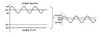
図3において、左側部分は、二次転写バイアスの交流成分と直流成分を分けて図示したものである。ここでは交流成分として正弦波状のものを用いており、プラス側のピーク値+aVと、マイナス側のピーク値−aVとを具備している。したがって、交流成分のピークツウピーク電圧Vppは2aVとなる。直流成分は−bVの電圧とする。 In FIG. 3, the left portion shows the AC component and DC component of the secondary transfer bias separately. Here, a sine wave-like component is used as an AC component, and it has a positive peak value + aV and a negative peak value -aV. Therefore, the peak-to-peak voltage Vpp of the AC component is 2 aV. The DC component is a voltage of -bV.
両者を重畳したものを図の右側部分に示してある。オフセット電圧Voffは、重畳バイアスの直流成分の値と同じである。上述したように、重畳バイアスは交流成分(Vpp)と直流成分(V)とを重畳したものであり、その時間平均値はオフセット電圧Voffと同じ値になる。0Vを中心にプラス側のピーク値とマイナス側のピーク値が同じ値の交流成分と、本例では−bVの電圧を有する直流成分とを重畳した結果、重畳バイアスはマイナス側にオフセットした正弦波状の波形となり、プラス側のピーク値「+(a−b)V」と、マイナス側のピーク値「−(a+b)V」とを具備している。 A superposition of both is shown in the right part of the figure. The offset voltage Voff is the same as the value of the DC component of the superimposed bias. As described above, the superimposed bias is obtained by superimposing the AC component (Vpp) and the DC component (V), and the time average value thereof is the same value as the offset voltage Voff. As a result of superimposing an alternating current component having the same positive peak value and negative peak value around 0V and a direct current component having a voltage of -bV in this example, the superimposed bias is a sine wave offset offset to the negative side. And has a positive peak value “+ (a−b) V” and a negative peak value “− (a + b) V”.
図3の右側部分に示す重畳バイアスにおいて、0Vから上のプラス側の部分は、トナーを記録紙側からベルト側に戻す方向に作用する部分であり、0Vから下のマイナス側の部分は、二次転写ニップ内でトナーを中間転写ベルト側から記録紙側に移動させる方向に作用する部分である。そして、時間平均値であるオフセット電圧Voffをトナーと同じ極性(本例ではマイナス)にすることで、トナーを往復移動させながら、相対的にはベルト側から記録紙側に移動させて記録紙上に転移させることが可能になる。 In the superimposed bias shown in the right side portion of FIG. 3, the plus side portion above 0V is a portion that acts in the direction of returning the toner from the recording paper side to the belt side, and the minus side portion below 0V is the second portion. This is a portion that acts in the direction of moving the toner from the intermediate transfer belt side to the recording paper side in the next transfer nip. Then, by setting the offset voltage Voff, which is a time average value, to the same polarity as the toner (minus in this example), the toner is reciprocally moved and relatively moved from the belt side to the recording paper side and onto the recording paper. It can be transferred.
和紙調の用紙やエンボス加工が施された用紙など、表面の凹凸の大きい記録用紙を用いる場合には、重畳バイアスを印加することにより、上述のように、トナーを往復移動させながら相対的にはベルト側から記録紙側に移動させて記録紙上に転移させることで、用紙凹部への転写性を向上させ、転写率の向上や中抜けなどの異常画像を改善させることができることが知られている。重畳バイアスにおいては、上記プラス側の部分が、凹凸紙に対する転写性の向上に寄与するものと言うことができる。また、上記マイナス側の部分は、通常の転写に必要な部分(トナーをベルト側から記録紙側に移動させる作用)と言うことができる。 When using recording paper with large surface irregularities, such as Japanese paper or embossed paper, by applying a superimposed bias, as described above, the toner is moved back and forth relatively. It is known that by transferring from the belt side to the recording paper and transferring it onto the recording paper, the transferability to the concave portion of the paper can be improved, and the transfer rate can be improved and abnormal images such as hollows can be improved. . In the superposition bias, it can be said that the plus side portion contributes to the improvement of transferability to the uneven paper. The minus side portion can be said to be a portion necessary for normal transfer (an effect of moving the toner from the belt side to the recording paper side).
ところで、本実施形態のプリンタにおいては、1色のトナーによる単色画像だけではなく、4色トナーによるフルカラー画像あるいは2色又は3色の多色画像を形成することが可能である。1色のトナーによる単色画像を転写させる場合に比べ、トナー量の多いフルカラー画像あるいは多色画像(以下、フルカラー画像と多色画像を総称してカラー画像と呼ぶ)を転写させる場合には、より転写性を高めることが要求される。例えば上述の特開2004−117920号公報(特許文献1)には、カラーモードによって、転写バイアスとして印加する直流電圧の値を変更することが提案されている。DC転写方式を用いる上記特許文献1においては、トナーの載り量差に起因する転写不良を防止するために、モノクロ画像を形成する場合の転写電圧よりもカラー画像を形成する場合の転写電圧を大きくしている。
By the way, in the printer of this embodiment, it is possible to form not only a single color image with one color toner but also a full color image with four color toners or a multicolor image with two or three colors. When transferring a full-color image or a multi-color image with a large amount of toner (hereinafter, the full-color image and the multi-color image are collectively referred to as a color image) compared to transferring a single-color image with a single color toner, It is required to improve transferability. For example, Japanese Patent Application Laid-Open No. 2004-117920 (Patent Document 1) described above proposes changing the value of a DC voltage applied as a transfer bias depending on a color mode. In
ところが、本願発明者が研究を重ねた結果、直流電圧に交流電圧を重畳させた重畳バイアスを用いるAC転写方式では、転写電圧に比例して転写性が向上するわけではなく、単純に転写電圧を大きくしても、トナーの載り量の多いカラー画像を良好に転写することができないことを見出した。その点について図4を参照して説明する。 However, as a result of repeated research by the inventors of the present application, in the AC transfer method using the superimposed bias in which the AC voltage is superimposed on the DC voltage, the transfer property is not improved in proportion to the transfer voltage, and the transfer voltage is simply set. It has been found that a color image with a large amount of applied toner cannot be transferred satisfactorily even if the size is increased. This will be described with reference to FIG.
仮に、図3に示す重畳バイアスで、ブラックトナーによるモノクロモード(単色モード)時に良好な転写性が得られていたとする。
そして、トナー載り量の多いカラーモード(カラー画像を形成する作像モード)時に対応すべく、図4に示すように、DC成分の電圧値を図3の「−bV」から「−cV」にアップさせたとする(c>b)。この場合、図4の右側部分に示すように、重畳バイアス波形においては、オフセット電圧は大きく(絶対値が大きく)なったものの、図に矢印で示す0Vから上のプラス側の部分、すなわちトナーを記録紙側からベルト側に戻す方向に作用する電界が小さく(図3の場合よりも小さく)なってしまったため、重畳バイアスの特徴であるトナーを往復移動させる作用が低減し、転写電圧(ここでは直流電圧)を大きくしたにもかからわず転写性のアップにつながらないことが分かった。
Assume that good transferability is obtained in the monochrome mode (monochrome mode) using black toner with the superimposed bias shown in FIG.
Then, as shown in FIG. 4, the DC component voltage value is changed from “−bV” to “−cV” in FIG. (C> b). In this case, as shown in the right part of FIG. 4, in the superimposed bias waveform, although the offset voltage is large (the absolute value is large), the plus part above 0 V indicated by the arrow in the figure, that is, the toner is applied. Since the electric field acting in the direction of returning from the recording paper side to the belt side has become small (smaller than in the case of FIG. 3), the action of reciprocating the toner, which is a feature of the superimposed bias, is reduced, and the transfer voltage (here, It was found that the transferability was not improved even though the DC voltage was increased.
そこで、本発明では、トナー載り量の多いカラーモード時には、図5に示すように、図中に斜線を付して示す0Vから上のプラス側の部分、すなわち、トナーを記録紙側からベルト側に戻す方向に作用する部分(戻し電界)を確保する(単色モード時と同程度以上確保する)ように、直流電圧及び交流電圧の双方を単色モード時から切り替える(変更する)。 Therefore, according to the present invention, in the color mode with a large amount of applied toner, as shown in FIG. 5, the portion on the plus side above 0 V indicated by hatching in the drawing, that is, the toner is transferred from the recording paper side to the belt side. The DC voltage and the AC voltage are both switched (changed) from the monochromatic mode so as to ensure a portion (return electric field) that acts in the direction to return to (ensure at least the same level as in the monochromatic mode).
これにより、図5と図3を比較して分かるように、オフセット電圧を大きくして転写性(トナーをベルト側から記録紙側に移動させる電界)をアップしつつ、かつ、単色モード時と同程度以上にトナー戻し電界(0Vから上のプラス側の部分)も確保できるため、トナー載り量の多いカラー画像(フルカラー画像、多色画像)を転写させるカラーモード時においても、良好な転写性を得ることができるようになった。しかも、トナー戻し電界が確保されるために、用紙表面の凹凸の大きな用紙に対しても用紙凹部への充分な転写性が得られるという効果もある。 Thus, as can be seen by comparing FIG. 5 and FIG. 3, the offset voltage is increased to improve transferability (electric field for moving the toner from the belt side to the recording paper side), and at the same time as in the monochrome mode. Since a toner return electric field (a positive portion above 0 V) can be secured more than about, good transferability can be obtained even in a color mode in which a color image (full color image, multicolor image) with a large amount of applied toner is transferred. Can now get. In addition, since the toner return electric field is ensured, there is also an effect that sufficient transfer property to the paper recess can be obtained even for paper with large unevenness on the paper surface.
なおここでは、重畳バイアスにおける直流成分及び交流成分の双方を電圧で制御する場合で説明したが、直流成分は電流制御でも良い。交流成分に関しては、電流制御が可能な電源構成はコスト高となるため、本実施形態では、直流成分を電流制御する場合でも交流成分は電圧制御とする。 Here, the case where both the DC component and the AC component in the superimposed bias are controlled by voltage has been described, but the DC component may be current control. Regarding the AC component, since the power supply configuration capable of current control is costly, in the present embodiment, even when the DC component is current-controlled, the AC component is voltage-controlled.
具体的な制御例を電圧制御の場合(実施例1)と、直流成分を電流制御した場合(実施例2)、の2例について示す。なお、ここでの転写性評価には凹凸紙である特殊製紙株式会社製のレザック66(商品名)、130kg用紙を使用した。 Specific examples of control are shown for two cases: voltage control (Example 1) and current control of a DC component (Example 2). Here, for the transferability evaluation, Rezac 66 (trade name) and 130 kg paper manufactured by Tokushu Paper Co., Ltd., which is an uneven paper, were used.
まず、直流成分及び交流成分の双方を定電圧制御した場合(実施例1)、ブラックカラーによるモノクロモード時(単色モード時)の重畳バイアスは、DC成分の電圧値が−0.8kV、AC成分のピークツウピーク電圧が7kVで良好な転写性を得られていた。転写性を5段階評価した(数値が高いほど優秀とする)官能テストでは、上記電圧値で評価結果「5」であった。上記電圧値は、図3に当てはめると、a=±3.5kVでAC成分のVpp=2aV=7kV,DC成分の電圧値V=−bV=−0.8kVとなる。重畳バイアスにおけるトナー戻し側の電圧のピーク値は、+(a−b)=+2.7kV、絶対値で2.7kVとなる。 First, when both the DC component and the AC component are controlled at a constant voltage (Example 1), the superimposed bias in the monochrome mode (in the monochrome mode) using black color has a DC component voltage value of −0.8 kV and an AC component. Good transferability was obtained when the peak-to-peak voltage was 7 kV. In the sensory test in which the transferability was evaluated in five stages (the higher the numerical value, the better), the evaluation result was “5” at the above voltage value. When the above voltage values are applied to FIG. 3, a = ± 3.5 kV, AC component Vpp = 2 aV = 7 kV, and DC component voltage value V = −bV = −0.8 kV. The peak value of the voltage on the toner return side in the superposition bias is + (ab) = + 2.7 kV, and the absolute value is 2.7 kV.
この電圧値のままカラーモードで評価したところ、評価結果「1」となった。そこで、DC成分の電圧値を−0.9Vに上げるとともに、AC成分のピークツウピーク電圧を9kVに上げたところ、評価結果「5」を得ることができた。これを図5に当てはめると、d=±4.5kVでAC成分のVpp=2dV=9kV,DC成分の電圧値V=−cV=−0.9kVとなる。重畳バイアスにおけるトナー戻し側の電圧のピーク値は、+(d−c)=+3.6kV、絶対値で3.6kVとなる。なお、直流及び交流の双方とも定電圧制御である。カラーモード時に、単色モード時と同程度以上のトナー戻し側の電圧の絶対値を確保することにより、トナー載り量が多い場合でも転写部においてトナーを往復移動させることができるため、良好な転写性を得ることができる。 When this voltage value was evaluated in the color mode, the evaluation result was “1”. Therefore, when the voltage value of the DC component was raised to −0.9 V and the peak-to-peak voltage of the AC component was raised to 9 kV, the evaluation result “5” could be obtained. When this is applied to FIG. 5, when d = ± 4.5 kV, the AC component Vpp = 2 dV = 9 kV, and the DC component voltage value V = −cV = −0.9 kV. The peak value of the voltage on the toner return side in the superposition bias is + (dc) = + 3.6 kV, and the absolute value is 3.6 kV. Both DC and AC are constant voltage control. By ensuring the absolute value of the voltage on the toner return side in the color mode that is equal to or higher than that in the single color mode, the toner can be reciprocated in the transfer section even when the amount of applied toner is large. Can be obtained.
次に、直流成分を定電流制御(交流成分は定電圧制御)した場合(実施例2)、ブラックカラーによるモノクロモード時(単色モード時)の重畳バイアスは、DC成分の電流値が−18μA、AC成分のピークツウピーク電圧が8kVで良好な転写性を得られていた。転写性を5段階評価した官能テストでは、上記電流値及び電圧値で評価結果「5」であった。 Next, when the DC component is subjected to constant current control (AC component is controlled to constant voltage) (Example 2), the superimposed bias at the time of black color monochrome mode (in monochrome mode) has a DC component current value of −18 μA, Good transferability was obtained when the peak-to-peak voltage of the AC component was 8 kV. In the sensory test in which the transferability was evaluated in five stages, the evaluation result was “5” based on the current value and the voltage value.
この値のままカラーモードで評価したところ、評価結果「1」となった。そこで、DC成分の電流値を−22μA、AC成分のピークツウピーク電圧を9kVに上げたところ、評価結果「5」を得ることができた。なお、直流成分は定電流制御、交流成分は定電圧制御である。直流成分を定電流制御することにより、直流成分を定電圧制御する場合と比べ、環境条件や紙種への対応性が向上する。 When this value was evaluated in the color mode, the evaluation result was “1”. Therefore, when the current value of the DC component was increased to −22 μA and the peak-to-peak voltage of the AC component was increased to 9 kV, the evaluation result “5” was obtained. The DC component is constant current control, and the AC component is constant voltage control. By controlling the direct current component at a constant current, compatibility with environmental conditions and paper types is improved as compared with the case where the direct current component is controlled at a constant voltage.
このように、重畳バイアスによる転写制御を行う画像形成装置において、カラーモード時には、重畳バイアスにおけるトナー戻し電界を確保するように、重畳バイアスの直流成分及び交流成分の双方を、単色モード時から切り替える制御によって、トナー載り量の多いカラーモード時においても、良好な転写性を得ることができ、かつ、凹凸の大きな用紙に対しても用紙凹部への良好な転写性を得ることができる。 As described above, in the image forming apparatus that performs the transfer control using the superimposed bias, in the color mode, the control to switch both the DC component and the AC component of the superimposed bias from the single color mode so as to ensure the toner return electric field in the superimposed bias. As a result, good transferability can be obtained even in the color mode with a large amount of applied toner, and good transferability to paper recesses can be obtained even for paper with large irregularities.
なお、上記実施例1及び実施例2は、ある機械を用いた場合の具体的な数値の一例を示したものであり、電圧又は電流の数値は、転写部の構成や用いている部材の材質、トナーの物性等に応じて適宜な値を設定すればよいものである。 The first and second embodiments are examples of specific numerical values when a certain machine is used, and the numerical values of the voltage or current are the material of the structure of the transfer portion and the member used. An appropriate value may be set according to the physical properties of the toner.
カラーモード時に、単色モード時と同程度以上のトナー戻し電界を確保することによって、トナー載り量が多い場合でも転写部においてトナーを往復移動させることができるため、良好な転写性を得ることができる。また、凹凸紙に対しても良好な転写性が得られる。 By ensuring a toner return electric field at the same level or higher in the color mode as in the single color mode, the toner can be reciprocated in the transfer portion even when the amount of applied toner is large, so that good transfer properties can be obtained. . Also, good transferability can be obtained for uneven paper.
カラーモード時に印加するバイアス(電圧又は/及び電流)を、単色モード時よりも大きくすることによて、トナー載り量が多いカラーモード時における転写不良を防ぎ、良好な転写性を得ることができる。また、凹凸紙に対しても良好な転写性が得られる。 By making the bias (voltage or / and current) applied in the color mode larger than that in the single color mode, it is possible to prevent transfer failure in the color mode with a large amount of applied toner and to obtain good transferability. . Also, good transferability can be obtained for uneven paper.
重畳バイアスの直流成分及び交流成分の双方を定電圧制御する場合には、電源構成のコスト上昇を抑制することができる。
重畳バイアスの直流成分を定電流制御することにより、定電圧制御する場合と比べ、環境条件や紙種への対応性が向上する。
When constant voltage control is performed on both the DC component and the AC component of the superimposed bias, an increase in the cost of the power supply configuration can be suppressed.
By controlling the direct current component of the superposed bias at a constant current, compatibility with environmental conditions and paper types is improved as compared with the case of controlling the constant voltage.
なお、上記実施例1及び実施例2では単色モード時とカラーモード時でバイアスを切り替える例を示したが、これに用紙種類を組み合わせることも可能である。例えば、凹凸が大きな用紙を用いたカラーモード時には、上記実施例1及び実施例2で例示した値よりも、さらに大きな電圧又は/及び電流値の重畳バイアスを印加するようにしても良い。用紙種類は画像形成装置が複写装置であれば通常、操作パネルから指定可能であるし、プリンタの場合はホストマシンからの印刷設定で指定可能である。カラーモードも同様に指定可能であるため、これらによって凹凸が大きな用紙を用いたカラーモードが指定された場合には、例えば、直流成分及び交流成分の双方を電圧制御する場合であれば、DC成分の電圧値を−0.9Vに、AC成分のピークツウピーク電圧を10kVに設定するなどである。 In the first embodiment and the second embodiment, the example in which the bias is switched between the single color mode and the color mode is shown. However, it is also possible to combine the paper type with this. For example, in the color mode using paper with large unevenness, a superimposed bias of a voltage or / and a current value larger than the values exemplified in the first and second embodiments may be applied. The paper type can usually be specified from the operation panel if the image forming apparatus is a copying apparatus, and can be specified by print settings from the host machine in the case of a printer. Since the color mode can be specified in the same manner, when the color mode using paper with large unevenness is specified by these, for example, in the case of controlling the voltage of both the DC component and the AC component, the DC component The voltage value of the AC component is set to -0.9V, and the peak-to-peak voltage of the AC component is set to 10 kV.
次に、用紙種類に対応する具体的な制御例を実施例3〜6として説明する。この実施例3〜6では、上記実施例2と同じく直流成分を定電流制御(交流成分は定電圧制御)するものとする。 Next, specific control examples corresponding to paper types will be described as third to sixth embodiments. In the third to sixth embodiments, the DC component is subjected to constant current control (the AC component is controlled to constant voltage) as in the second embodiment.
[実施例3]
実施例3で用いる用紙(以下、紙種A)は、体積抵抗率が10.77[LogΩ・cm]、用紙おもて面の表面抵抗率は12.76[LogΩ/□]、用紙裏面の表面抵抗率は12.40[LogΩ/□]、溝深さは約50μmである。溝深さの測定は株式会社キーエンス製レーザ顕微鏡VK−9500を用いておこない、サンプル用紙中の最大凹凸量を「溝深さ」とした。
[Example 3]
The paper (hereinafter referred to as paper type A) used in Example 3 has a volume resistivity of 10.77 [LogΩ · cm], a surface resistivity of the front surface of the paper of 12.76 [LogΩ / □], and a back surface of the paper. The surface resistivity is 12.40 [LogΩ / □], and the groove depth is about 50 μm. The measurement of the groove depth was performed using a laser microscope VK-9500 manufactured by Keyence Corporation, and the maximum unevenness in the sample paper was defined as “groove depth”.
ブラックカラーによるモノクロモード時(単色モード時)の重畳バイアスは、DC成分の電流値が−40μA、AC成分のピークツウピーク電圧が3.7kVで良好な転写性を得られていた。転写性を5段階評価した官能テストでは、上記電流値及び電圧値で評価結果「5」であった。 In the black and white monochrome mode (monochrome mode), the DC bias current value was −40 μA, the AC component peak-to-peak voltage was 3.7 kV, and good transferability was obtained. In the sensory test in which the transferability was evaluated in five stages, the evaluation result was “5” based on the current value and the voltage value.
また、紙種Aへの転写時の、DC成分の電圧値は、温度23℃、相対湿度50%の標準環境において、−0.7kVであった。バイアスの直流成分は定電流制御されるため、転写時の電圧値は環境等により変動するが、−0.7kVの±30%の範囲であった。 The voltage value of the DC component at the time of transfer to paper type A was −0.7 kV in a standard environment at a temperature of 23 ° C. and a relative humidity of 50%. Since the direct current component of the bias is controlled at a constant current, the voltage value at the time of transfer varies depending on the environment and the like, but is within a range of ± 30% of −0.7 kV.
この値のままカラーモードで評価したところ、評価結果「1」となった。そこで、DC成分の電流値を−70μA、AC成分のピークツウピーク電圧を6.2kVに上げたところ、評価結果「5」を得ることができた。 When this value was evaluated in the color mode, the evaluation result was “1”. Therefore, when the current value of the DC component was increased to -70 μA and the peak-to-peak voltage of the AC component was increased to 6.2 kV, the evaluation result “5” was obtained.
また、紙種Aへの転写時の、DC成分の電圧値は、温度23℃、相対湿度50%の標準環境において、−1kVであった。バイアスの直流成分は定電流制御されるため、転写時の電圧値は環境等により変動するが、電圧値の変動範囲は低温低湿環境から高温高湿環境のすべてにおいて−1kVの±30%の範囲内であった。 Further, the voltage value of the DC component at the time of transfer to the paper type A was −1 kV in a standard environment at a temperature of 23 ° C. and a relative humidity of 50%. Since the DC component of the bias is controlled at a constant current, the voltage value at the time of transfer varies depending on the environment, etc., but the voltage value varies in a range of ± 30% of −1 kV in all of the low temperature and low humidity environment to the high temperature and high humidity environment. It was in.
なお、直流成分は定電流制御、交流成分は定電圧制御である。直流成分を定電流制御することにより、直流成分を定電圧制御する場合と比べ、環境条件や紙種への対応性が向上する。 The DC component is constant current control, and the AC component is constant voltage control. By controlling the direct current component at a constant current, compatibility with environmental conditions and paper types is improved as compared with the case where the direct current component is controlled at a constant voltage.
このように、重畳バイアスによる転写制御を行う画像形成装置において、カラーモード時には、重畳バイアスにおけるトナー戻し力を確保するように、重畳バイアスの直流成分及び交流成分の双方を、単色モード時から切り替える制御によって、トナー載り量の多いカラーモード時においても、良好な転写性を得ることができ、かつ、凹凸の大きな用紙に対しても用紙凹部への良好な転写性を得ることができる。 As described above, in an image forming apparatus that performs transfer control using a superimposing bias, in the color mode, control for switching both the DC component and the AC component of the superimposing bias from that in the monochromatic mode so as to ensure the toner returning force in the superimposing bias. As a result, good transferability can be obtained even in the color mode with a large amount of applied toner, and good transferability to paper recesses can be obtained even for paper with large irregularities.
モノクロモード時(単色モード時)の重畳バイアスの上記電圧値は、図3に当てはめると、a=±1.85kVでAC成分のVpp=2aV=3.7kV,DC成分の電圧値V=−bV=−0.7kVとなる。重畳バイアスにおけるトナー戻し側の電圧のピーク値は、+(a−b)=+1.15kV、絶対値で1.15kVとなる。 When applied to FIG. 3, the voltage value of the superimposed bias in the monochrome mode (in the monochrome mode) is a = ± 1.85 kV, AC component Vpp = 2 aV = 3.7 kV, and DC component voltage value V = −bV. = −0.7 kV. The peak value of the voltage on the toner return side in the superposition bias is + (ab) = + 1.15 kV, and the absolute value is 1.15 kV.
この電圧値のままカラーモードで評価したところ、評価結果「1」となった。そこで、DC成分の電圧値を−1.0kVに上げるとともに、AC成分のピークツウピーク電圧を6.2kVに上げたところ、評価結果「5」を得ることができた。これを図5に当てはめると、d=±3.1kVでAC成分のVpp=2dV=6.2kV,DC成分の電圧値V=−cV=−1.0kVとなる。重畳バイアスにおけるトナー戻し側の電圧のピーク値は、+(d−c)=+2.1kV、絶対値で2.1kVとなる。なお、直流及び交流の双方とも定電圧制御である。カラーモード時に、単色モード時と同程度以上のトナー戻し側の電圧の絶対値を確保することにより、トナー載り量が多い場合でも転写部においてトナーを往復移動させることができるため、良好な転写性を得ることができる。 When this voltage value was evaluated in the color mode, the evaluation result was “1”. Therefore, when the voltage value of the DC component was increased to −1.0 kV and the peak-to-peak voltage of the AC component was increased to 6.2 kV, the evaluation result “5” was obtained. When this is applied to FIG. 5, when d = ± 3.1 kV, the AC component Vpp = 2 dV = 6.2 kV, and the DC component voltage value V = −cV = −1.0 kV. The peak value of the voltage on the toner return side in the superposition bias is + (dc) = + 2.1 kV, and the absolute value is 2.1 kV. Both DC and AC are constant voltage control. By ensuring the absolute value of the voltage on the toner return side in the color mode that is equal to or higher than that in the single color mode, the toner can be reciprocated in the transfer section even when the amount of applied toner is large. Can be obtained.
バイアスの直流成分は定電流制御されるため、転写時の電圧値は環境等により変動するが、低温低湿環境から高温高湿環境のすべてにおいて、温度23℃、相対湿度50%の標準環境の場合と同様、カラーモード時のトナー戻し側の電圧の絶対値(kV)は、単色モード時のトナー戻し側の電圧の絶対値(kV)と同程度以上の大きさであった。 Since the DC component of the bias is controlled at a constant current, the voltage value at the time of transfer varies depending on the environment, etc., but in a standard environment with a temperature of 23 ° C. and a relative humidity of 50% in all of the low temperature and low humidity environment to the high temperature and high humidity environment. Similarly, the absolute value (kV) of the voltage on the toner return side in the color mode is equal to or larger than the absolute value (kV) of the voltage on the toner return side in the single color mode.
[実施例4]
実施例4で用いる用紙(以下、紙種B)は、体積抵抗率が10.96[LogΩ・cm]、用紙おもて面の表面抵抗率は13.10[LogΩ/□]、用紙裏面の表面抵抗率は13.25[LogΩ/□]、溝深さは100μmである。溝深さの測定は株式会社キーエンス製レーザ顕微鏡VK−9500を用いておこない、サンプル用紙中の最大凹凸量を「溝深さ」とした。
[Example 4]
The paper used in Example 4 (hereinafter, paper type B) has a volume resistivity of 10.96 [Log Ω · cm], a surface resistivity of the front surface of the paper of 13.10 [Log Ω / □], and a back surface of the paper. The surface resistivity is 13.25 [LogΩ / □], and the groove depth is 100 μm. The measurement of the groove depth was performed using a laser microscope VK-9500 manufactured by Keyence Corporation, and the maximum unevenness in the sample paper was defined as “groove depth”.
ブラックカラーによるモノクロモード時(単色モード時)の重畳バイアスは、DC成分の電流値が−40μA、AC成分のピークツウピーク電圧が4.0kVで良好な転写性を得られていた。転写性を5段階評価した官能テストでは、上記電流値及び電圧値で評価結果「5」であった。 In the black and white monochrome mode (monochrome mode), the DC bias current value was −40 μA and the AC component peak-to-peak voltage was 4.0 kV, and good transferability was obtained. In the sensory test in which the transferability was evaluated in five stages, the evaluation result was “5” based on the current value and the voltage value.
また、紙種Bへの転写時の、DC成分の電圧値は、温度23℃、相対湿度50%の標準環境において、−0.7kVであった。バイアスの直流成分は定電流制御されるため、転写時の電圧値は環境等により変動するが、−0.7kVの±30%の範囲であった。 The voltage value of the DC component at the time of transfer to the paper type B was −0.7 kV in a standard environment at a temperature of 23 ° C. and a relative humidity of 50%. Since the direct current component of the bias is controlled at a constant current, the voltage value at the time of transfer varies depending on the environment and the like, but is within a range of ± 30% of −0.7 kV.
この値のままカラーモードで評価したところ、評価結果「1」となった。そこで、DC成分の電流値を−70μA、AC成分のピークツウピーク電圧を6.4kVに上げたところ、評価結果「5」を得ることができた。 When this value was evaluated in the color mode, the evaluation result was “1”. Therefore, when the current value of the DC component was increased to -70 μA and the peak-to-peak voltage of the AC component was increased to 6.4 kV, the evaluation result “5” was obtained.
また、紙種Bへの転写時の、DC成分の電圧値は、温度23℃、相対湿度50%の標準環境において、−1.1kVであった。バイアスの直流成分は定電流制御されるため、転写時の電圧値は環境等により変動するが、電圧値の変動範囲は低温低湿環境から高温高湿環境のすべてにおいて−1.1kVの±30%の範囲内であった。 The voltage value of the DC component at the time of transfer to the paper type B was −1.1 kV in a standard environment at a temperature of 23 ° C. and a relative humidity of 50%. Since the DC component of the bias is controlled at a constant current, the voltage value at the time of transfer varies depending on the environment and the like, but the range of voltage value variation is −30% of −1.1 kV in all of the low temperature and low humidity environment to the high temperature and high humidity environment. It was in the range.
なお、直流成分は定電流制御、交流成分は定電圧制御である。直流成分を定電流制御することにより、直流成分を定電圧制御する場合と比べ、環境条件や紙種への対応性が向上する。 The DC component is constant current control, and the AC component is constant voltage control. By controlling the direct current component at a constant current, compatibility with environmental conditions and paper types is improved as compared with the case where the direct current component is controlled at a constant voltage.
このように、重畳バイアスによる転写制御を行う画像形成装置において、カラーモード時には、重畳バイアスにおけるトナー戻し力を確保するように、重畳バイアスの直流成分及び交流成分の双方を、単色モード時から切り替える制御によって、トナー載り量の多いカラーモード時においても、良好な転写性を得ることができ、かつ、凹凸の大きな用紙に対しても用紙凹部への良好な転写性を得ることができる。 As described above, in an image forming apparatus that performs transfer control using a superimposing bias, in the color mode, control for switching both the DC component and the AC component of the superimposing bias from that in the monochromatic mode so as to ensure the toner returning force in the superimposing bias. As a result, good transferability can be obtained even in the color mode with a large amount of applied toner, and good transferability to paper recesses can be obtained even for paper with large irregularities.
モノクロモード時(単色モード時)の重畳バイアスの上記電圧値は、図3に当てはめると、a=±2.0kVでAC成分のVpp=2aV=4.0kV,DC成分の電圧値V=−bV=−0.7kVとなる。重畳バイアスにおけるトナー戻し側の電圧のピーク値は、+(a−b)=+1.30kV、絶対値で1.30kVとなる。 When applied to FIG. 3, the voltage value of the superimposed bias in the monochrome mode (in the monochrome mode) is a = ± 2.0 kV, AC component Vpp = 2 aV = 4.0 kV, and DC component voltage value V = −bV. = −0.7 kV. The peak value of the voltage on the toner return side in the superposition bias is + (ab) = + 1.30 kV, and the absolute value is 1.30 kV.
この電圧値のままカラーモードで評価したところ、評価結果「1」となった。そこで、DC成分の電圧値を−1.1kVに上げるとともに、AC成分のピークツウピーク電圧を6.4kVに上げたところ、評価結果「5」を得ることができた。これを図5に当てはめると、d=±3.2kVでAC成分のVpp=2dV=6.4kV,DC成分の電圧値V=−cV=−1.1kVとなる。重畳バイアスにおけるトナー戻し側の電圧のピーク値は、+(d−c)=+2.1kV、絶対値で2.1kVとなる。なお、直流及び交流の双方とも定電圧制御である。カラーモード時に、単色モード時と同程度以上のトナー戻し側の電圧の絶対値を確保することにより、トナー載り量が多い場合でも転写部においてトナーを往復移動させることができるため、良好な転写性を得ることができる。 When this voltage value was evaluated in the color mode, the evaluation result was “1”. Therefore, when the voltage value of the DC component was increased to −1.1 kV and the peak-to-peak voltage of the AC component was increased to 6.4 kV, the evaluation result “5” could be obtained. When this is applied to FIG. 5, when d = ± 3.2 kV, the AC component Vpp = 2 dV = 6.4 kV, and the DC component voltage value V = −cV = −1.1 kV. The peak value of the voltage on the toner return side in the superposition bias is + (dc) = + 2.1 kV, and the absolute value is 2.1 kV. Both DC and AC are constant voltage control. By ensuring the absolute value of the voltage on the toner return side in the color mode that is equal to or higher than that in the single color mode, the toner can be reciprocated in the transfer section even when the amount of applied toner is large. Can be obtained.
バイアスの直流成分は定電流制御されるため、転写時の電圧値は環境等により変動するが、低温低湿環境から高温高湿環境のすべてにおいて、温度23℃、相対湿度50%の標準環境の場合と同様、カラーモード時のトナー戻し側の電圧の絶対値(kV)は、単色モード時のトナー戻し側の電圧の絶対値(kV)と同程度以上の大きさであった。 Since the DC component of the bias is controlled at a constant current, the voltage value at the time of transfer varies depending on the environment, etc., but in a standard environment with a temperature of 23 ° C. and a relative humidity of 50% in all of the low temperature and low humidity environment to the high temperature and high humidity environment. Similarly, the absolute value (kV) of the voltage on the toner return side in the color mode is equal to or larger than the absolute value (kV) of the voltage on the toner return side in the single color mode.
[実施例5]
実施例5で用いる用紙(以下、紙種C)は、体積抵抗率が11.18[LogΩ・cm]、用紙おもて面の表面抵抗率は12.99[LogΩ/□]、用紙裏面の表面抵抗率は13.11[LogΩ/□]、溝深さは約80μmである。溝深さの測定は株式会社キーエンス製レーザ顕微鏡VK−9500を用いておこない、サンプル用紙中の最大凹凸量を「溝深さ」とした。
[Example 5]
The paper used in Example 5 (hereinafter, paper type C) has a volume resistivity of 11.18 [Log Ω · cm], a surface resistivity of the front surface of the paper of 12.99 [Log Ω / □], and a back surface of the paper. The surface resistivity is 13.11 [LogΩ / □], and the groove depth is about 80 μm. The measurement of the groove depth was performed using a laser microscope VK-9500 manufactured by Keyence Corporation, and the maximum unevenness in the sample paper was defined as “groove depth”.
ブラックカラーによるモノクロモード時(単色モード時)の重畳バイアスは、DC成分の電流値が−40μA、AC成分のピークツウピーク電圧が4.3kVで良好な転写性を得られていた。転写性を5段階評価した官能テストでは、上記電流値及び電圧値で評価結果「5」であった。 In the black and white monochrome mode (monochrome mode), the bias value of the DC component was −40 μA, the peak-to-peak voltage of the AC component was 4.3 kV, and good transferability was obtained. In the sensory test in which the transferability was evaluated in five stages, the evaluation result was “5” based on the current value and the voltage value.
また、紙種Cへの転写時の、DC成分の電圧値は、温度23℃、相対湿度50%の標準環境において、−0.9kVであった。バイアスの直流成分は定電流制御されるため、転写時の電圧値は環境等により変動するが、−0.9kVの±30%の範囲であった。 The voltage value of the DC component at the time of transfer to the paper type C was −0.9 kV in a standard environment at a temperature of 23 ° C. and a relative humidity of 50%. Since the direct current component of the bias is controlled at a constant current, the voltage value at the time of transfer varies depending on the environment or the like, but is within a range of ± 30% of −0.9 kV.
この値のままカラーモードで評価したところ、評価結果「1」となった。そこで、DC成分の電流値を−70μA、AC成分のピークツウピーク電圧を6.7kVに上げたところ、評価結果「5」を得ることができた。 When this value was evaluated in the color mode, the evaluation result was “1”. Therefore, when the current value of the DC component was increased to −70 μA and the peak-to-peak voltage of the AC component was increased to 6.7 kV, the evaluation result “5” was obtained.
また、紙種Cへの転写時の、DC成分の電圧値は、温度23℃、相対湿度50%の標準環境において、−1.3kVであった。バイアスの直流成分は定電流制御されるため、転写時の電圧値は環境等により変動するが、電圧値の変動範囲は低温低湿環境から高温高湿環境のすべてにおいて−1.3kVの±30%の範囲内であった。 Further, the voltage value of the DC component at the time of transfer to the paper type C was −1.3 kV in a standard environment at a temperature of 23 ° C. and a relative humidity of 50%. Since the DC component of the bias is controlled at a constant current, the voltage value at the time of transfer varies depending on the environment or the like, but the voltage value fluctuation range is ± 30% of −1.3 kV in all of the low temperature and low humidity environment to the high temperature and high humidity environment. It was in the range.
なお、直流成分は定電流制御、交流成分は定電圧制御である。直流成分を定電流制御することにより、直流成分を定電圧制御する場合と比べ、環境条件や紙種への対応性が向上する。 The DC component is constant current control, and the AC component is constant voltage control. By controlling the direct current component at a constant current, compatibility with environmental conditions and paper types is improved as compared with the case where the direct current component is controlled at a constant voltage.
このように、重畳バイアスによる転写制御を行う画像形成装置において、カラーモード時には、重畳バイアスにおけるトナー戻し力を確保するように、重畳バイアスの直流成分及び交流成分の双方を、単色モード時から切り替える制御によって、トナー載り量の多いカラーモード時においても、良好な転写性を得ることができ、かつ、凹凸の大きな用紙に対しても用紙凹部への良好な転写性を得ることができる。 As described above, in an image forming apparatus that performs transfer control using a superimposing bias, in the color mode, control for switching both the DC component and the AC component of the superimposing bias from that in the monochromatic mode so as to ensure the toner returning force in the superimposing bias. As a result, good transferability can be obtained even in the color mode with a large amount of applied toner, and good transferability to paper recesses can be obtained even for paper with large irregularities.
モノクロモード時(単色モード時)の重畳バイアスの上記電圧値は、図3に当てはめると、a=±2.15kVでAC成分のVpp=2aV=4.3kV,DC成分の電圧値V=−bV=−0.9kVとなる。重畳バイアスにおけるトナー戻し側の電圧のピーク値は、+(a−b)=+1.25kV、絶対値で1.25kVとなる。 When applied to FIG. 3, the voltage value of the superimposed bias in the monochrome mode (monochrome mode) is a = ± 2.15 kV, AC component Vpp = 2 aV = 4.3 kV, and DC component voltage value V = −bV. = -0.9 kV. The peak value of the voltage on the toner return side in the superposition bias is + (ab) = + 1.25 kV, and the absolute value is 1.25 kV.
この電圧値のままカラーモードで評価したところ、評価結果「1」となった。そこで、DC成分の電圧値を−1.3kVに上げるとともに、AC成分のピークツウピーク電圧を6.7kVに上げたところ、評価結果「5」を得ることができた。これを図5に当てはめると、d=±3.35kVでAC成分のVpp=2dV=6.7kV,DC成分の電圧値V=−cV=−1.3kVとなる。重畳バイアスにおけるトナー戻し側の電圧のピーク値は、+(d−c)=+2.05kV、絶対値で2.05kVとなる。なお、直流及び交流の双方とも定電圧制御である。カラーモード時に、単色モード時と同程度以上のトナー戻し側の電圧の絶対値を確保することにより、トナー載り量が多い場合でも転写部においてトナーを往復移動させることができるため、良好な転写性を得ることができる。 When this voltage value was evaluated in the color mode, the evaluation result was “1”. Therefore, when the voltage value of the DC component was increased to −1.3 kV and the peak-to-peak voltage of the AC component was increased to 6.7 kV, the evaluation result “5” could be obtained. When this is applied to FIG. 5, when d = ± 3.35 kV, the AC component Vpp = 2 dV = 6.7 kV and the DC component voltage value V = −cV = −1.3 kV. The peak value of the voltage on the toner return side in the superposition bias is + (dc) = + 2.05 kV, and the absolute value is 2.05 kV. Both DC and AC are constant voltage control. By ensuring the absolute value of the voltage on the toner return side in the color mode that is equal to or higher than that in the single color mode, the toner can be reciprocated in the transfer section even when the amount of applied toner is large. Can be obtained.
バイアスの直流成分は定電流制御されるため、転写時の電圧値は環境等により変動するが、低温低湿環境から高温高湿環境のすべてにおいて、温度23℃、相対湿度50%の標準環境の場合と同様、カラーモード時のトナー戻し側の電圧の絶対値(kV)は、単色モード時のトナー戻し側の電圧の絶対値(kV)と同程度以上の大きさであった。 Since the DC component of the bias is controlled at a constant current, the voltage value at the time of transfer varies depending on the environment, etc., but in a standard environment with a temperature of 23 ° C. and a relative humidity of 50% in all of the low temperature and low humidity environment to the high temperature and high humidity environment. Similarly, the absolute value (kV) of the voltage on the toner return side in the color mode is equal to or larger than the absolute value (kV) of the voltage on the toner return side in the single color mode.
[実施例6]
実施例6で用いる用紙(以下、紙種D)は、体積抵抗率が10.92[LogΩ・cm]、用紙おもて面の表面抵抗率は12.62[LogΩ/□]、用紙裏面の表面抵抗率は12.37[LogΩ/□]、溝深さは約110μmである。溝深さの測定は株式会社キーエンス製レーザ顕微鏡VK−9500を用いておこない、サンプル用紙中の最大凹凸量を「溝深さ」とした。
[Example 6]
The paper used in Example 6 (hereinafter, paper type D) has a volume resistivity of 10.92 [LogΩ · cm], a surface resistivity of the front surface of the paper of 12.62 [LogΩ / □], The surface resistivity is 12.37 [LogΩ / □], and the groove depth is about 110 μm. The measurement of the groove depth was performed using a laser microscope VK-9500 manufactured by Keyence Corporation, and the maximum unevenness in the sample paper was defined as “groove depth”.
ブラックカラーによるモノクロモード時(単色モード時)の重畳バイアスは、DC成分の電流値が−40μA、AC成分のピークツウピーク電圧が5.5kVで良好な転写性を得られていた。転写性を5段階評価した官能テストでは、上記電流値及び電圧値で評価結果「5」であった。 In the black and white monochrome mode (monochrome mode), the bias component had a DC component current value of −40 μA and an AC component peak-to-peak voltage of 5.5 kV, and good transferability was obtained. In the sensory test in which the transferability was evaluated in five stages, the evaluation result was “5” based on the current value and the voltage value.
また、紙種Dへの転写時の、DC成分の電圧値は、温度23℃、相対湿度50%の標準環境において、−1.4kVであった。バイアスの直流成分は定電流制御されるため、転写時の電圧値は環境等により変動するが、−1.4kVの±30%の範囲であった。 The voltage value of the DC component at the time of transfer to the paper type D was −1.4 kV in a standard environment at a temperature of 23 ° C. and a relative humidity of 50%. Since the direct current component of the bias is controlled at a constant current, the voltage value at the time of transfer varies depending on the environment or the like, but is in the range of ± 30% of −1.4 kV.
この値のままカラーモードで評価したところ、評価結果「1」となった。そこで、DC成分の電流値を−70μA、AC成分のピークツウピーク電圧を8.9kVに上げたところ、評価結果「5」を得ることができた。 When this value was evaluated in the color mode, the evaluation result was “1”. Therefore, when the current value of the DC component was increased to -70 μA and the peak-to-peak voltage of the AC component was increased to 8.9 kV, the evaluation result “5” was obtained.
また、紙種Dへの転写時の、DC成分の電圧値は、温度23℃、相対湿度50%の標準環境において、−2.1kVであった。バイアスの直流成分は定電流制御されるため、転写時の電圧値は環境等により変動するが、電圧値の変動範囲は低温低湿環境から高温高湿環境のすべてにおいて−2.1kVの±30%の範囲内であった。 The voltage value of the DC component at the time of transfer to the paper type D was −2.1 kV in a standard environment at a temperature of 23 ° C. and a relative humidity of 50%. Since the DC component of the bias is controlled at a constant current, the voltage value at the time of transfer varies depending on the environment, etc., but the voltage value varies in a range of ± 2.1% of −2.1 kV in all of the low temperature and low humidity environment to the high temperature and high humidity environment. It was in the range.
なお、直流成分は定電流制御、交流成分は定電圧制御である。直流成分を定電流制御することにより、直流成分を定電圧制御する場合と比べ、環境条件や紙種への対応性が向上する。 The DC component is constant current control, and the AC component is constant voltage control. By controlling the direct current component at a constant current, compatibility with environmental conditions and paper types is improved as compared with the case where the direct current component is controlled at a constant voltage.
このように、重畳バイアスによる転写制御を行う画像形成装置において、カラーモード時には、重畳バイアスにおけるトナー戻し力を確保するように、重畳バイアスの直流成分及び交流成分の双方を、単色モード時から切り替える制御によって、トナー載り量の多いカラーモード時においても、良好な転写性を得ることができ、かつ、凹凸の大きな用紙に対しても用紙凹部への良好な転写性を得ることができる。 As described above, in an image forming apparatus that performs transfer control using a superimposing bias, in the color mode, control for switching both the DC component and the AC component of the superimposing bias from that in the monochromatic mode so as to ensure the toner returning force in the superimposing bias. As a result, good transferability can be obtained even in the color mode with a large amount of applied toner, and good transferability to paper recesses can be obtained even for paper with large irregularities.
モノクロモード時(単色モード時)の重畳バイアスの上記電圧値は、図3に当てはめると、a=±2.75kVでAC成分のVpp=2aV=5.5kV,DC成分の電圧値V=−bV=−1.4kVとなる。重畳バイアスにおけるトナー戻し側の電圧のピーク値は、+(a−b)=+1.35kV、絶対値で1.35kVとなる。 When applied to FIG. 3, the voltage value of the superimposed bias in the monochrome mode (in the monochrome mode) is a = ± 2.75 kV, AC component Vpp = 2 aV = 5.5 kV, and DC component voltage value V = −bV. = -1.4 kV. The peak value of the voltage on the toner return side in the superposition bias is + (ab) = 1.35 kV, and the absolute value is 1.35 kV.
この電圧値のままカラーモードで評価したところ、評価結果「1」となった。そこで、DC成分の電圧値を−2.1kVに上げるとともに、AC成分のピークツウピーク電圧を8.9kVに上げたところ、評価結果「5」を得ることができた。これを図5に当てはめると、d=±4.45kVでAC成分のVpp=2dV=8.9kV,DC成分の電圧値V=−cV=−2.1kVとなる。重畳バイアスにおけるトナー戻し側の電圧のピーク値は、+(d−c)=+2.35kV、絶対値で2.35kVとなる。なお、直流及び交流の双方とも定電圧制御である。カラーモード時に、単色モード時と同程度以上のトナー戻し側の電圧の絶対値を確保することにより、トナー載り量が多い場合でも転写部においてトナーを往復移動させることができるため、良好な転写性を得ることができる。 When this voltage value was evaluated in the color mode, the evaluation result was “1”. Therefore, when the voltage value of the DC component was increased to -2.1 kV and the peak-to-peak voltage of the AC component was increased to 8.9 kV, the evaluation result “5” was obtained. When this is applied to FIG. 5, d = ± 4.45 kV, AC component Vpp = 2 dV = 8.9 kV, and DC component voltage value V = −cV = −2.1 kV. The peak value of the voltage on the toner return side in the superposition bias is + (dc) = + 2.35 kV, and the absolute value is 2.35 kV. Both DC and AC are constant voltage control. By ensuring the absolute value of the voltage on the toner return side in the color mode that is equal to or higher than that in the single color mode, the toner can be reciprocated in the transfer section even when the amount of applied toner is large. Can be obtained.
バイアスの直流成分は定電流制御されるため、転写時の電圧値は環境等により変動するが、低温低湿環境から高温高湿環境のすべてにおいて、温度23℃、相対湿度50%の標準環境の場合と同様、カラーモード時のトナー戻し側の電圧の絶対値(kV)は、単色モード時のトナー戻し側の電圧の絶対値(kV)と同程度以上の大きさであった。 Since the DC component of the bias is controlled at a constant current, the voltage value at the time of transfer varies depending on the environment, etc., but in a standard environment with a temperature of 23 ° C. and a relative humidity of 50% in all of the low temperature and low humidity environment to the high temperature and high humidity environment. Similarly, the absolute value (kV) of the voltage on the toner return side in the color mode is equal to or larger than the absolute value (kV) of the voltage on the toner return side in the single color mode.
次に、トナー像を用紙へ転写する際の重畳バイアスとして、互いに異なる重畳バイアスを出力する複数のモードを有しており、出力画像に応じてモードを切り替える(重畳転写バイアスを変更する)実施例(実施例7)について説明する。 Next, there is a plurality of modes for outputting different superposition biases as superposition biases when transferring the toner image to the paper, and the mode is switched according to the output image (the superposition transfer bias is changed). (Example 7) will be described.
本実施例では、複数のモードとして、標準モードと、標準モードよりも重畳バイアスのAC成分のピークツウピーク電圧が小さなモード(ハーフトーン優先モード)と、標準モードよりも重畳バイアスのAC成分のピークツウピーク電圧が大きなモード(ベタ優先モード)と、を有するものである。 In this embodiment, as a plurality of modes, a standard mode, a mode in which the peak-to-peak voltage of the AC component of the superimposed bias is smaller than that of the standard mode (halftone priority mode), and the peak of the AC component of the superimposed bias than the standard mode are used. And a mode with a large toe peak voltage (solid priority mode).
用紙への出力画像中に含まれる単位面積あたりのトナー量(用紙中の画像面積率に対応)は、出力対象の画像ごとに異なる。このトナー量が異なると、トナーを移動させるために最適な電圧、電流値(「トナーを往復移動させながら相対的にはベルト側から記録紙側に移動させて記録紙上に転移させることで、用紙凹部への転写性を向上させ、転写率の向上や中抜けなどの異常画像を改善」できる電圧、電流値)も異なる。 The amount of toner per unit area included in the output image on the paper (corresponding to the image area ratio in the paper) differs for each image to be output. If the amount of toner is different, the optimum voltage and current value for moving the toner (“the paper is moved by moving it from the belt side to the recording paper side relatively while moving the toner back and forth, and transferring it onto the recording paper. The voltage and current value) that can improve the transferability to the recesses, improve the transfer rate, and improve abnormal images such as voids are also different.
そこで、ユーザまたはサービスマンは、出力対象の画像の上記トナー量に応じて、操作パネルまたはホストマシンからの印刷設定によりこれらの複数のモードのうちから一つを指定する。例えば、出力対象の画像がグレー色の画像など濃度の薄い画像の場合はハーフトーン優先モードを指定し、出力対象の画像が濃度の濃い画像の場合はベタ優先モードを選択する。これにより、トナー量に応じて最適な電圧、電流値により転写することができ、「用紙凹部への転写性を向上させ、転写率の向上や中抜けなどの異常画像を改善」できる。 Therefore, the user or service person designates one of the plurality of modes according to the print setting from the operation panel or the host machine according to the toner amount of the image to be output. For example, the halftone priority mode is designated when the output target image is a light image such as a gray image, and the solid priority mode is selected when the output target image is a dark image. As a result, transfer can be performed with an optimal voltage and current value according to the toner amount, and “transferability to a paper recess can be improved, and transfer images can be improved and abnormal images such as voids can be improved”.
上述の紙種Aを使用する場合、ブラックカラーによるモノクロモード時(単色モード時)の重畳バイアスは、標準モードが指定されたときは、DC成分の電流値を−40μA、AC成分のピークツウピーク電圧を3.7kVに設定する。ハーフトーン優先モードが指定されたときは、DC成分の電流値を−40μA、AC成分のピークツウピーク電圧を3.2kVに設定する。ベタ優先モードが指定されたときは、DC成分の電流値を−40μA、AC成分のピークツウピーク電圧を4.6kVに設定する。一方、カラーモード時の重畳バイアスは、標準モードが指定されたときは、DC成分の電流値を−70μA、AC成分のピークツウピーク電圧を6.2kVに設定する。ハーフトーン優先モードが指定されたときは、DC成分の電流値を−70μA、AC成分のピークツウピーク電圧を5.4kVに設定する。ベタ優先モードが指定されたときは、DC成分の電流値を−70μA、AC成分のピークツウピーク電圧を7.0kVに設定する。 When the above-mentioned paper type A is used, the superimposing bias in the monochrome mode (in the monochrome mode) by the black color is -40 μA for the DC component current value and the peak-to-peak of the AC component when the standard mode is designated. Set the voltage to 3.7 kV. When the halftone priority mode is designated, the DC component current value is set to −40 μA, and the AC component peak-to-peak voltage is set to 3.2 kV. When the solid priority mode is designated, the current value of the DC component is set to −40 μA, and the peak-to-peak voltage of the AC component is set to 4.6 kV. On the other hand, when the standard mode is designated, the superimposed bias in the color mode is set such that the current value of the DC component is −70 μA and the peak-to-peak voltage of the AC component is 6.2 kV. When the halftone priority mode is designated, the DC component current value is set to -70 μA, and the AC component peak-to-peak voltage is set to 5.4 kV. When the solid priority mode is designated, the current value of the DC component is set to -70 μA, and the peak-to-peak voltage of the AC component is set to 7.0 kV.
上述の紙種Bを使用する場合、ブラックカラーによるモノクロモード時(単色モード時)の重畳バイアスは、標準モードが指定されたときは、DC成分の電流値を−40μA、AC成分のピークツウピーク電圧を4.0kVに設定する。ハーフトーン優先モードが指定されたときは、DC成分の電流値を−40μA、AC成分のピークツウピーク電圧を3.3kVに設定する。ベタ優先モードが指定されたときは、DC成分の電流値を−40μA、AC成分のピークツウピーク電圧を4.9kVに設定する。一方、カラーモード時の重畳バイアスは、標準モードが指定されたときは、DC成分の電流値を−70μA、AC成分のピークツウピーク電圧を6.4kVに設定する。ハーフトーン優先モードが指定されたときは、DC成分の電流値を−70μA、AC成分のピークツウピーク電圧を5.6kVに設定する。ベタ優先モードが指定されたときは、DC成分の電流値を−70μA、AC成分のピークツウピーク電圧を7.3kVに設定する。 When the above-mentioned paper type B is used, the superimposing bias in the monochrome mode (in the monochrome mode) using the black color is -40 μA in the DC component current value and the peak-to-peak in the AC component when the standard mode is designated. Set the voltage to 4.0 kV. When the halftone priority mode is designated, the DC component current value is set to −40 μA, and the AC component peak-to-peak voltage is set to 3.3 kV. When the solid priority mode is designated, the current value of the DC component is set to −40 μA, and the peak-to-peak voltage of the AC component is set to 4.9 kV. On the other hand, the superposition bias in the color mode is set such that the current value of the DC component is −70 μA and the peak-to-peak voltage of the AC component is 6.4 kV when the standard mode is designated. When the halftone priority mode is designated, the DC component current value is set to -70 μA, and the AC component peak-to-peak voltage is set to 5.6 kV. When the solid priority mode is designated, the current value of the DC component is set to -70 μA, and the peak-to-peak voltage of the AC component is set to 7.3 kV.
上述の紙種Cを使用する場合、ブラックカラーによるモノクロモード時(単色モード時)の重畳バイアスは、標準モードが指定されたときは、DC成分の電流値を−40μA、AC成分のピークツウピーク電圧を4.3kVに設定する。ハーフトーン優先モードが指定されたときは、DC成分の電流値を−40μA、AC成分のピークツウピーク電圧を3.6kVに設定する。ベタ優先モードが指定されたときは、DC成分の電流値を−40μA、AC成分のピークツウピーク電圧を5.5kVに設定する。一方、カラーモード時の重畳バイアスは、標準モードが指定されたときは、DC成分の電流値を−70μA、AC成分のピークツウピーク電圧を6.7kVに設定する。ハーフトーン優先モードが指定されたときは、DC成分の電流値を−70μA、AC成分のピークツウピーク電圧を6.0kVに設定する。ベタ優先モードが指定されたときは、DC成分の電流値を−70μA、AC成分のピークツウピーク電圧を8.0kVに設定する。 When using the above-mentioned paper type C, the superimposing bias in the monochrome mode (in the monochrome mode) with black color is -40 μA for the DC component current value and the peak-to-peak of the AC component when the standard mode is designated. Set the voltage to 4.3 kV. When the halftone priority mode is designated, the DC component current value is set to −40 μA, and the AC component peak-to-peak voltage is set to 3.6 kV. When the solid priority mode is designated, the current value of the DC component is set to −40 μA, and the peak-to-peak voltage of the AC component is set to 5.5 kV. On the other hand, when the standard mode is designated, the superimposed bias in the color mode is set such that the DC component current value is −70 μA and the AC component peak-to-peak voltage is 6.7 kV. When the halftone priority mode is designated, the DC component current value is set to -70 μA, and the AC component peak-to-peak voltage is set to 6.0 kV. When the solid priority mode is designated, the current value of the DC component is set to -70 μA, and the peak-to-peak voltage of the AC component is set to 8.0 kV.
上述の紙種Dを使用する場合、ブラックカラーによるモノクロモード時(単色モード時)の重畳バイアスは、標準モードが指定されたときは、DC成分の電流値を−40μA、AC成分のピークツウピーク電圧を5.5kVに設定する。ハーフトーン優先モードが指定されたときは、DC成分の電流値を−40μA、AC成分のピークツウピーク電圧を4.1kVに設定する。ベタ優先モードが指定されたときは、DC成分の電流値を−40μA、AC成分のピークツウピーク電圧を6.5kVに設定する。一方、カラーモード時の重畳バイアスは、標準モードが指定されたときは、DC成分の電流値を−70μA、AC成分のピークツウピーク電圧を8.9kVに設定する。ハーフトーン優先モードが指定されたときは、DC成分の電流値を−70μA、AC成分のピークツウピーク電圧を7.9kVに設定する。ベタ優先モードが指定されたときは、DC成分の電流値を−70μA、AC成分のピークツウピーク電圧を10.0kVに設定する。 When the above-mentioned paper type D is used, the superimposing bias in the monochrome mode (in the monochrome mode) with black color is -40 μA for the DC component current value and the peak-to-peak of the AC component when the standard mode is designated. Set the voltage to 5.5 kV. When the halftone priority mode is designated, the DC component current value is set to −40 μA, and the AC component peak-to-peak voltage is set to 4.1 kV. When the solid priority mode is designated, the current value of the DC component is set to −40 μA, and the peak-to-peak voltage of the AC component is set to 6.5 kV. On the other hand, when the standard mode is designated, the superimposed bias in the color mode is set such that the DC component current value is −70 μA and the AC component peak-to-peak voltage is 8.9 kV. When the halftone priority mode is designated, the current value of the DC component is set to -70 μA, and the peak-to-peak voltage of the AC component is set to 7.9 kV. When the solid priority mode is designated, the DC component current value is set to -70 μA, and the AC component peak-to-peak voltage is set to 10.0 kV.
このように、出力画像に応じて重畳転写バイアスを切り替えることにより、トナー量に応じて最適な電圧、電流値により転写をすることができ、用紙凹部への転写性を向上させ、転写率の向上や中抜けなどの異常画像を改善することができる。 In this way, by switching the superimposed transfer bias according to the output image, it is possible to perform transfer with the optimum voltage and current value according to the toner amount, improving the transferability to the concave portion of the paper, and improving the transfer rate. And abnormal images such as omissions can be improved.
なお、上記各実施例は、ある機械を用いた場合の具体的な数値の一例を示したものであり、電圧又は電流の数値は、転写部の構成や用いている部材の材質、トナーの物性等に応じて適宜な値を設定すればよいものである。 Each of the above embodiments shows an example of specific numerical values when a certain machine is used. The numerical values of voltage or current are the structure of the transfer portion, the material of the member used, and the physical properties of the toner. An appropriate value may be set according to the above.
画像形成装置の構成に関し、図1に示す構成では、二次転写部は転写ニップを形成する構成であり、図示例では中間転写ベルト51を挟んで二次転写裏面ローラ53にニップ形成ローラ56を圧接させているが、ニップ形成ローラに代えて搬送ベルト(転写ベルト)を用いてもよい。
With regard to the configuration of the image forming apparatus, in the configuration shown in FIG. 1, the secondary transfer unit is configured to form a transfer nip. In the illustrated example, the
また、二次転写部を非接触方式に構成することも可能である。その場合、非接触方式の転写手段である転写チャージャを二次転写裏面ローラ53に対向するように配置し、その転写チャージャに重畳バイアスを印加する。その重畳バイアスの直流成分の極性はトナー帯電極性と逆極性とし、中間転写ベルト51上のトナー像を、二次転写裏面ローラ53及びベルト51と転写チャージャ間に通紙される用紙上に、吸引転写させる。
It is also possible to configure the secondary transfer portion in a non-contact manner. In that case, a transfer charger, which is a non-contact type transfer means, is arranged so as to face the secondary transfer back
さらに、本発明は中間転写方式(間接転写方式)の画像形成装置に限らず、例えば、図6に示すような、感光体上のトナー像を直接記録用紙に転写する直接転写方式の装置にも適用できる。この直接転写方式のカラープリンタは、記録用紙が給紙ローラ32により搬送ベルト131へ送られ、各色の感光体ドラム2(2Y,2C,2M,2K)から記録用紙へ各色の画像が順次直接転写され、定着装置50により定着される。各転写部に印加する転写バイアスとして、直流電圧に交流電圧を重畳せしめたもの(重畳バイアス)を用いる。そして、上記説明したように、カラーモード時には、重畳バイアスにおけるトナー戻し電界を確保するように、重畳バイアスの直流成分及び交流成分の双方を、単色モード時から切り替える。
Furthermore, the present invention is not limited to an intermediate transfer type (indirect transfer type) image forming apparatus, but also to a direct transfer type apparatus that directly transfers a toner image on a photoreceptor onto a recording sheet, as shown in FIG. Applicable. In this direct transfer type color printer, the recording paper is fed to the conveying
また、図7に示すように、所謂1ドラム型のカラー画像形成装置にも本発明を適用できる。この1ドラム型のカラー画像形成装置は、1つの感光体201の周囲に、それぞれ、帯電手段203、イエロー,シアン,マゼンタ,黒の各色に対応した現像ユニット204(Y,C,M,K)などを有している。画像形成を行う場合、まず、感光体201の表面を帯電手段203で一様に帯電した後、感光体201の表面に対してY用画像データで変調されたレーザ光Lを照射して、感光体201の表面にY用静電潜像を形成する。そして、このY用静電潜像を現像ユニット204YによりYトナーで現像を行う。これにより得られたY用トナー像は、中間転写ベルト206上に一次転写される。その後、感光体201の表面に残留した転写残トナーをクリーニング装置220で除去した後、再び感光体201の表面を帯電手段203で一様に帯電する。次に、感光体201の表面に対してM用画像データで変調されたレーザ光Lを照射して、感光体201の表面にM用静電潜像を形成する。そして、このM用静電潜像を現像ユニット204MによりMトナーで現像を行う。これにより得られたM用トナー像は、中間転写ベルト206上に既に一次転写されているY用トナー像と重なり合うようにして、中間転写ベルト206上に一次転写される。以後、C及びKについても、同様に中間転写ベルト206上に一次転写する。このようにして互いに重なり合った状態の中間転写ベルト206上の各色トナー像は、二次転写ニップに搬送されてきた記録用紙上に転写される。トナー像が転写された記録用紙は、定着ユニット400に搬送される。この定着ユニット400で、記録用紙を加熱、加圧して、記録用紙上のトナー像を記録用紙に定着させる。定着後の記録用紙は、図示しない排紙トレイ上に排出する。
Further, as shown in FIG. 7, the present invention can be applied to a so-called one-drum type color image forming apparatus. In this one-drum type color image forming apparatus, a developing unit 204 (Y, C, M, K) corresponding to each of the charging unit 203, yellow, cyan, magenta, and black is provided around one
この1ドラム型のカラー画像形成装置の二次転写部は、二次転写裏面ローラ209及びニップ形成ローラ207を有する構成であり、図1のプリンタと同じく、二次転写裏面ローラ209に重畳バイアスを印加し、ニップ形成ローラ207を接地した構成となっている。そして、上記説明したように、カラーモード時には、重畳バイアスにおけるトナー戻し電界を確保するように、重畳バイアスの直流成分及び交流成分の双方を、単色モード時から切り替える。 The secondary transfer portion of the one-drum type color image forming apparatus has a secondary transfer back surface roller 209 and a nip forming roller 207, and applies a superimposed bias to the secondary transfer back surface roller 209 as in the printer of FIG. The nip forming roller 207 is grounded by application. As described above, in the color mode, both the DC component and the AC component of the superimposed bias are switched from those in the monochromatic mode so as to ensure the toner return electric field in the superimposed bias.
最後に、転写部の構成が異なる変形例について説明する。この変形例に対しても、上記各実施形態と同様、本発明を適用することで、同様の効果を得ることができる。
図8に示す変形例は、中間転写体(本例では中間転写ベルト)702に二次転写搬送ベルト703を接触させ、転写ニップにて記録媒体Pに画像を転写させた後、二次転写搬送ベルト703で搬送する方式である。記録媒体Pはレジストローラ706から送出後、中間転写ベルト702と二次転写搬送ベルト703が圧接される転写ニップを通過する際に記録媒体Pに画像が転写され、中間転写ベルト702から分離させた記録媒体を二次転写搬送ベルト703によって搬送し、図示しない定着装置へと送る。
Finally, modified examples in which the configuration of the transfer unit is different will be described. Also in this modified example, the same effect can be obtained by applying the present invention as in the above embodiments.
In the modification shown in FIG. 8, the secondary
転写ニップを構成する中間転写ベルト702側の裏面ローラ704をバイアス印加ローラとし、該ローラ704にトナー帯電極性(正規帯電極性)とは逆極性のバイアスを印加する、斥力転写方式、あるいは、転写ニップを構成する二次転写搬送ベルト703側の対向ローラ705をバイアス印加ローラとし、該ローラ705にトナー帯電極性(正規帯電極性)と同極性のバイアスを印加する、引力転写方式、のいずれも採用可能である。
A repulsive transfer method or transfer nip in which a
さらに、二次転写搬送ベルト703の内部に、転写バイアスローラ又は/及びバイアス印加ブラシを設け、これらの転写バイアスローラ又は/及びバイアス印加ブラシに転写バイアスを印加する構成も可能である。転写バイアスローラ又は/及びバイアス印加ブラシの配置場所としては、転写ニップの直下でもよいし下流側近傍でもよい。転写ローラ(転写バイアスローラ)は発泡層(弾性層)を有してもよいし、表層にコーティングを施しても良い。また、転写チャージャを用いる構成も可能である。
Further, it is also possible to provide a transfer bias roller or / and a bias application brush inside the secondary
以上、本発明を図示例により説明したが、本発明はこれに限定されるものではない。転写部の構成は適宜な構成を採用可能であり、対向部材側をベルトで構成しても良い。また、チャージャを用いた非接触方式も採用可能である。重畳バイアスを出力可能な電源は周知であり、適宜な構成の電源を使用可能である。 As mentioned above, although this invention was demonstrated by the example of illustration, this invention is not limited to this. An appropriate configuration can be adopted as the configuration of the transfer portion, and the opposing member side may be configured by a belt. A non-contact method using a charger can also be employed. A power source capable of outputting the superimposed bias is well known, and a power source having an appropriate configuration can be used.
また、画像形成装置の構成も任意であり、タンデム式における各色作像ユニットの並び順などは任意である。また、4色機に限らず、3色のトナーを用いるフルカラー機や、2色のトナーによる多色機にも本発明を適用することができる。もちろん、画像形成装置としてはプリンタに限らず、複写機やファクシミリ、あるいは複数の機能を備える複合機であっても良い。 The configuration of the image forming apparatus is also arbitrary, and the arrangement order of the color image forming units in the tandem system is arbitrary. The present invention can be applied not only to a four-color machine but also to a full-color machine using three-color toners and a multi-color machine using two-color toners. Of course, the image forming apparatus is not limited to a printer, and may be a copier, a facsimile machine, or a multifunction machine having a plurality of functions.
1 画像形成ユニット
11 感光体ドラム
21 帯電装置
31 現像装置
41 クリーニング装置
50 転写ユニット
51 中間転写ベルト
53 二次転写裏面ローラ
55 一次転写ローラ
56 ニップ形成ローラ
80 光書込ユニット
90 定着装置
200 二次転写バイアス電源
DESCRIPTION OF
Claims (11)
複数色のトナーからなるトナー像を転写するカラーモードと、単色のトナーからなるトナー像を転写する単色モードと、を有し、
前記バイアスは、記録媒体から前記像担持体へとトナーを戻す極性のピーク電圧を有し、
前記カラーモード時の前記ピーク電圧の絶対値は、前記単色モード時の前記ピーク電圧の絶対値以上であることを特徴とする画像形成装置。 In an image forming apparatus that applies a bias whose polarity is alternately switched and transfers a toner image charged to a predetermined polarity from an image carrier to a recording medium.
A color mode for transferring a toner image composed of a plurality of color toners and a single color mode for transferring a toner image composed of a single color toner;
The bias has a peak voltage of polarity for returning toner from the recording medium to the image carrier,
The image forming apparatus according to claim 1, wherein an absolute value of the peak voltage in the color mode is equal to or greater than an absolute value of the peak voltage in the monochrome mode.
複数色のトナーからなるトナー像を転写するカラーモードと、単色のトナーからなるトナー像を転写する単色モードと、を有し、
前記バイアスは、前記像担持体から記録媒体へとトナーを移動させる方向の電界と、記録媒体から前記像担持体へとトナーを戻す方向の戻し電界と、を交互に形成し、
前記カラーモード時の前記戻し電界のピークの絶対値は、前記単色モード時の前記戻し電界のピークの絶対値以上であることを特徴とする画像形成装置。 In an image forming apparatus that applies a bias and transfers a toner image charged to a predetermined polarity from an image carrier to a recording medium.
A color mode for transferring a toner image composed of a plurality of color toners and a single color mode for transferring a toner image composed of a single color toner;
The bias alternately forms an electric field in the direction of moving the toner from the image carrier to the recording medium and a return electric field in a direction of returning the toner from the recording medium to the image carrier,
The absolute value of the peak of the return electric field in the color mode is equal to or greater than the absolute value of the peak of the return electric field in the monochrome mode.
前記指定手段により指定されたモードが、前記単位面積あたりのトナー量の多いモードであるほど、前記ピークツウピーク電圧を大きくすることを特徴とする、請求項3〜7のいずれか1項に記載の画像形成装置。 Designating means for designating any one of a plurality of modes in which toner amounts per unit area included in the toner image are different from each other;
8. The peak-to-peak voltage is increased as the mode designated by the designation unit is a mode in which the toner amount per unit area is larger. Image forming apparatus.
前記転写ニップで前記トナー像を前記像担持体から記録媒体へ転写するために前記バイアスを出力する電源と、を備えることを特徴とする請求項1乃至9のいずれか1項に記載の画像形成装置。The image forming apparatus according to claim 1, further comprising: a power source that outputs the bias for transferring the toner image from the image carrier to a recording medium at the transfer nip. apparatus.
前記転写ニップで前記ベルトの裏面に配置される裏面部材を備え、A back surface member disposed on the back surface of the belt at the transfer nip;
前記電源は、前記ニップ形成部材または前記裏面部材へ前記バイアスを出力することを特徴とする請求項10に記載の画像形成装置。The image forming apparatus according to claim 10, wherein the power source outputs the bias to the nip forming member or the back surface member.
Priority Applications (3)
| Application Number | Priority Date | Filing Date | Title |
|---|---|---|---|
| JP2012060062A JP5696678B2 (en) | 2011-06-28 | 2012-03-16 | Image forming apparatus |
| US13/483,536 US9323170B2 (en) | 2011-06-28 | 2012-05-30 | Image forming apparatus with a controller to set transfer bias |
| US15/076,031 US9864307B2 (en) | 2011-06-28 | 2016-03-21 | Image forming apparatus with a controller to set transfer bias |
Applications Claiming Priority (3)
| Application Number | Priority Date | Filing Date | Title |
|---|---|---|---|
| JP2011142861 | 2011-06-28 | ||
| JP2011142861 | 2011-06-28 | ||
| JP2012060062A JP5696678B2 (en) | 2011-06-28 | 2012-03-16 | Image forming apparatus |
Publications (3)
| Publication Number | Publication Date |
|---|---|
| JP2013033205A JP2013033205A (en) | 2013-02-14 |
| JP2013033205A5 JP2013033205A5 (en) | 2014-09-25 |
| JP5696678B2 true JP5696678B2 (en) | 2015-04-08 |
Family
ID=47390820
Family Applications (1)
| Application Number | Title | Priority Date | Filing Date |
|---|---|---|---|
| JP2012060062A Active JP5696678B2 (en) | 2011-06-28 | 2012-03-16 | Image forming apparatus |
Country Status (2)
| Country | Link |
|---|---|
| US (2) | US9323170B2 (en) |
| JP (1) | JP5696678B2 (en) |
Families Citing this family (34)
| Publication number | Priority date | Publication date | Assignee | Title |
|---|---|---|---|---|
| JP5678841B2 (en) | 2011-06-02 | 2015-03-04 | 株式会社リコー | Image forming apparatus |
| JP5900056B2 (en) | 2011-06-08 | 2016-04-06 | 株式会社リコー | Image forming apparatus |
| US8755723B2 (en) | 2011-09-28 | 2014-06-17 | Ricoh Company, Ltd. | Image forming apparatus and method of eliminating a charge on a recording medium by applying an AC voltage |
| JP6065406B2 (en) | 2011-10-11 | 2017-01-25 | 株式会社リコー | Transfer device and image forming apparatus |
| JP5721005B2 (en) | 2011-12-26 | 2015-05-20 | 株式会社リコー | Image forming apparatus |
| JP6083199B2 (en) | 2012-01-11 | 2017-02-22 | 株式会社リコー | Image forming apparatus |
| CN103226314B (en) | 2012-01-26 | 2016-04-13 | 株式会社理光 | Transfer device and image processing system |
| JP6035771B2 (en) | 2012-02-20 | 2016-11-30 | 株式会社リコー | Transfer device and image forming apparatus |
| JP5967469B2 (en) | 2012-03-12 | 2016-08-10 | 株式会社リコー | Image forming apparatus |
| JP6222542B2 (en) | 2012-05-18 | 2017-11-01 | 株式会社リコー | Image forming apparatus |
| JP5729403B2 (en) | 2012-07-25 | 2015-06-03 | 株式会社リコー | Image forming apparatus |
| JP6019965B2 (en) | 2012-09-10 | 2016-11-02 | 株式会社リコー | Image forming apparatus |
| JP2014077982A (en) | 2012-09-18 | 2014-05-01 | Ricoh Co Ltd | Transfer device and image forming apparatus |
| JP2014077998A (en) | 2012-09-18 | 2014-05-01 | Ricoh Co Ltd | Transfer device, image forming apparatus, and power source control method |
| JP6102490B2 (en) | 2012-09-18 | 2017-03-29 | 株式会社リコー | Image forming apparatus |
| JP6187857B2 (en) | 2013-02-14 | 2017-08-30 | 株式会社リコー | Transfer device and image forming apparatus |
| JP2014170116A (en) | 2013-03-04 | 2014-09-18 | Ricoh Co Ltd | Image forming apparatus |
| JP6369060B2 (en) | 2013-03-15 | 2018-08-08 | 株式会社リコー | Power supply device and image forming apparatus |
| JP6427898B2 (en) | 2013-05-30 | 2018-11-28 | 株式会社リコー | Image forming apparatus |
| JP6355021B2 (en) | 2014-06-25 | 2018-07-11 | 株式会社リコー | Image forming apparatus |
| JP6489409B2 (en) | 2014-10-15 | 2019-03-27 | 株式会社リコー | Image forming apparatus |
| WO2016088197A1 (en) * | 2014-12-02 | 2016-06-09 | キヤノン株式会社 | Image forming device |
| US9395658B2 (en) | 2014-12-09 | 2016-07-19 | Ricoh Company, Ltd. | Image forming apparatus |
| JP2016109969A (en) | 2014-12-09 | 2016-06-20 | 株式会社リコー | Image formation device |
| JP2016156958A (en) * | 2015-02-24 | 2016-09-01 | 株式会社リコー | Image forming apparatus |
| US9817341B2 (en) | 2015-03-18 | 2017-11-14 | Ricoh Company, Ltd. | Image forming apparatus |
| JP2016177044A (en) | 2015-03-19 | 2016-10-06 | 株式会社リコー | Image formation device |
| US9740156B2 (en) | 2015-03-19 | 2017-08-22 | Ricoh Company, Ltd. | Image forming apparatus that adjusts a transfer bias according to surface properties of a transfer target |
| JP6492956B2 (en) | 2015-05-15 | 2019-04-03 | 株式会社リコー | Image forming apparatus |
| JP2016218152A (en) | 2015-05-15 | 2016-12-22 | 株式会社リコー | Image formation apparatus |
| JP6679842B2 (en) * | 2015-05-18 | 2020-04-15 | 富士ゼロックス株式会社 | Image forming apparatus and transfer voltage setting method |
| US9703252B2 (en) | 2015-07-24 | 2017-07-11 | Ricoh Company, Ltd. | Power supply controlling device, power supply device, image forming apparatus, and power supply controlling method |
| US10067454B2 (en) * | 2016-04-14 | 2018-09-04 | Ricoh Company, Ltd. | Image forming apparatus |
| KR20210042767A (en) * | 2019-10-10 | 2021-04-20 | 휴렛-팩커드 디벨롭먼트 컴퍼니, 엘.피. | Controlling charging voltage |
Family Cites Families (47)
| Publication number | Priority date | Publication date | Assignee | Title |
|---|---|---|---|---|
| JPS60113273A (en) | 1983-11-24 | 1985-06-19 | Ricoh Co Ltd | Controller of developer layer thickness |
| JPS6329767A (en) * | 1986-07-23 | 1988-02-08 | Konica Corp | Colored picture forming device |
| JP2637095B2 (en) | 1987-03-12 | 1997-08-06 | 株式会社リコー | Developing device |
| US5029840A (en) | 1988-08-30 | 1991-07-09 | Ricoh Company, Ltd. | Automatic sheet feeder for an image recording apparatus |
| JP2908504B2 (en) * | 1990-03-30 | 1999-06-21 | 株式会社リコー | Image forming device |
| JP3200179B2 (en) | 1991-10-24 | 2001-08-20 | 株式会社リコー | Transfer device for image forming device |
| JPH09319219A (en) * | 1996-05-28 | 1997-12-12 | Sanyo Electric Co Ltd | Image forming device |
| JPH10319746A (en) * | 1997-05-22 | 1998-12-04 | Sanyo Electric Co Ltd | Image forming device |
| JP3608646B2 (en) | 1997-07-18 | 2005-01-12 | 株式会社リコー | Image forming apparatus and intermediate transfer unit used in the apparatus |
| JP3859112B2 (en) | 2000-02-28 | 2006-12-20 | 株式会社リコー | Image forming apparatus |
| JP3963638B2 (en) | 2000-09-07 | 2007-08-22 | 株式会社リコー | Image forming apparatus |
| EP1271259B1 (en) | 2001-06-26 | 2013-11-20 | Ricoh Company, Ltd. | Image forming apparatus and process cartridge therefor |
| JP2003029541A (en) | 2001-07-13 | 2003-01-31 | Ricoh Co Ltd | Image forming device |
| JP4004020B2 (en) | 2001-07-23 | 2007-11-07 | 株式会社リコー | Bias application method, bias application device, and image forming apparatus |
| JP2003131497A (en) | 2001-10-29 | 2003-05-09 | Ricoh Co Ltd | Tranfer device and image forming device using the same |
| US6901234B2 (en) | 2002-03-18 | 2005-05-31 | Ricoh Company, Ltd. | Image forming apparatus including an intermediate image transfer belt and high resistance contact member |
| JP2004117920A (en) * | 2002-09-26 | 2004-04-15 | Canon Inc | Image forming device |
| US7003238B2 (en) | 2002-11-05 | 2006-02-21 | Ricoh Company, Ltd. | Intermediate image transfer device for a color image forming apparatus |
| US7203433B2 (en) | 2003-06-25 | 2007-04-10 | Ricoh Company, Ltd. | Apparatus for detecting amount of toner deposit and controlling density of image, method of forming misalignment correction pattern, and apparatus for detecting and correcting misalignment of image |
| JP4778671B2 (en) | 2003-07-02 | 2011-09-21 | 株式会社リコー | Method for determining resistance change of transfer member used in image forming apparatus |
| JP2005070527A (en) | 2003-08-26 | 2005-03-17 | Ricoh Co Ltd | Cleaning device and image forming device |
| JP2006267486A (en) * | 2005-03-23 | 2006-10-05 | Fuji Xerox Co Ltd | Image forming apparatus |
| JP2007057902A (en) * | 2005-08-25 | 2007-03-08 | Seiko Epson Corp | Image forming apparatus |
| JP2007328317A (en) | 2006-05-08 | 2007-12-20 | Ricoh Co Ltd | Transfer-separation device and image forming apparatus |
| JP2008233357A (en) | 2007-03-19 | 2008-10-02 | Ricoh Co Ltd | Transfer nip roller, transfer apparatus and image forming apparatus |
| JP2009103830A (en) * | 2007-10-22 | 2009-05-14 | Kyocera Mita Corp | Image forming apparatus |
| JP5369488B2 (en) | 2008-05-08 | 2013-12-18 | 株式会社リコー | Transfer device and image forming apparatus |
| JP5370838B2 (en) | 2008-08-13 | 2013-12-18 | 株式会社リコー | Image forming apparatus |
| JP5505759B2 (en) | 2008-09-17 | 2014-05-28 | 株式会社リコー | Image forming apparatus |
| JP5423155B2 (en) | 2008-10-01 | 2014-02-19 | 株式会社リコー | Image forming apparatus |
| JP5268020B2 (en) | 2008-10-22 | 2013-08-21 | 株式会社リコー | Image forming apparatus |
| US8433221B2 (en) | 2008-12-04 | 2013-04-30 | Ricoh Company, Ltd. | Image forming apparatus with transfer nip adjustment function |
| JP5299772B2 (en) | 2009-03-02 | 2013-09-25 | 株式会社リコー | Image forming apparatus |
| JP4850928B2 (en) | 2009-06-02 | 2012-01-11 | シャープ株式会社 | Transfer device and image forming apparatus |
| JP5489556B2 (en) * | 2009-06-30 | 2014-05-14 | キヤノン株式会社 | Image forming apparatus |
| JP5522510B2 (en) | 2009-09-15 | 2014-06-18 | 株式会社リコー | Transfer device and image forming apparatus equipped with the transfer device |
| JP5375592B2 (en) | 2009-12-24 | 2013-12-25 | 株式会社リコー | Transfer device and image forming apparatus using the same |
| JP5644347B2 (en) | 2010-01-28 | 2014-12-24 | 株式会社リコー | Power control apparatus, image forming apparatus, and power control program |
| JP2011175060A (en) | 2010-02-24 | 2011-09-08 | Ricoh Co Ltd | Image forming apparatus |
| JP5424123B2 (en) * | 2010-03-16 | 2014-02-26 | 株式会社リコー | Image forming apparatus |
| JP5440952B2 (en) | 2010-05-19 | 2014-03-12 | 株式会社リコー | Image forming apparatus |
| JP2011248270A (en) | 2010-05-31 | 2011-12-08 | Ricoh Co Ltd | Image forming device |
| JP5707787B2 (en) | 2010-06-10 | 2015-04-30 | 株式会社リコー | Transfer device and image forming apparatus using the same |
| JP6189577B2 (en) * | 2010-08-18 | 2017-08-30 | 株式会社リコー | Transfer apparatus, image forming apparatus, and transfer method |
| JP5522538B2 (en) * | 2010-08-20 | 2014-06-18 | 株式会社リコー | Transfer device, image forming apparatus, transfer method, and image forming method |
| JP5585870B2 (en) * | 2010-08-20 | 2014-09-10 | 株式会社リコー | Image forming apparatus |
| JP5799783B2 (en) * | 2011-03-09 | 2015-10-28 | 株式会社リコー | Transfer device, image forming device |
-
2012
- 2012-03-16 JP JP2012060062A patent/JP5696678B2/en active Active
- 2012-05-30 US US13/483,536 patent/US9323170B2/en active Active
-
2016
- 2016-03-21 US US15/076,031 patent/US9864307B2/en active Active
Also Published As
| Publication number | Publication date |
|---|---|
| US9323170B2 (en) | 2016-04-26 |
| US20130004190A1 (en) | 2013-01-03 |
| US20160202644A1 (en) | 2016-07-14 |
| US9864307B2 (en) | 2018-01-09 |
| JP2013033205A (en) | 2013-02-14 |
Similar Documents
| Publication | Publication Date | Title |
|---|---|---|
| JP5696678B2 (en) | Image forming apparatus | |
| JP5900056B2 (en) | Image forming apparatus | |
| JP5678841B2 (en) | Image forming apparatus | |
| JP5729362B2 (en) | Image forming apparatus | |
| JP5729403B2 (en) | Image forming apparatus | |
| JP5967469B2 (en) | Image forming apparatus | |
| JP5787207B2 (en) | Image forming apparatus | |
| JP6065406B2 (en) | Transfer device and image forming apparatus | |
| JP5888588B2 (en) | Transfer device and image forming apparatus | |
| JP6012929B2 (en) | Image forming apparatus | |
| JP2017138627A (en) | Transfer device | |
| JP6008247B2 (en) | Image forming apparatus | |
| US20160195837A1 (en) | Image forming apparatus | |
| JP5858186B2 (en) | Image forming apparatus | |
| JP6284000B2 (en) | Image forming apparatus | |
| JP6119328B2 (en) | Transfer device and image forming apparatus | |
| JP5804174B2 (en) | Image forming apparatus | |
| JP6172593B2 (en) | Image forming apparatus | |
| JP2017194667A (en) | Image forming apparatus | |
| JP6897410B2 (en) | Image forming device | |
| JP2015175951A (en) | image forming apparatus |
Legal Events
| Date | Code | Title | Description |
|---|---|---|---|
| A621 | Written request for application examination |
Free format text: JAPANESE INTERMEDIATE CODE: A621 Effective date: 20140718 |
|
| A521 | Request for written amendment filed |
Free format text: JAPANESE INTERMEDIATE CODE: A523 Effective date: 20140813 |
|
| A871 | Explanation of circumstances concerning accelerated examination |
Free format text: JAPANESE INTERMEDIATE CODE: A871 Effective date: 20140813 |
|
| A975 | Report on accelerated examination |
Free format text: JAPANESE INTERMEDIATE CODE: A971005 Effective date: 20140911 |
|
| A131 | Notification of reasons for refusal |
Free format text: JAPANESE INTERMEDIATE CODE: A131 Effective date: 20140924 |
|
| A521 | Request for written amendment filed |
Free format text: JAPANESE INTERMEDIATE CODE: A523 Effective date: 20141121 |
|
| TRDD | Decision of grant or rejection written | ||
| A01 | Written decision to grant a patent or to grant a registration (utility model) |
Free format text: JAPANESE INTERMEDIATE CODE: A01 Effective date: 20150113 |
|
| A61 | First payment of annual fees (during grant procedure) |
Free format text: JAPANESE INTERMEDIATE CODE: A61 Effective date: 20150126 |
|
| R151 | Written notification of patent or utility model registration |
Ref document number: 5696678 Country of ref document: JP Free format text: JAPANESE INTERMEDIATE CODE: R151 |