JP5695536B2 - Imaging apparatus, imaging method, and program - Google Patents
Imaging apparatus, imaging method, and program Download PDFInfo
- Publication number
- JP5695536B2 JP5695536B2 JP2011218186A JP2011218186A JP5695536B2 JP 5695536 B2 JP5695536 B2 JP 5695536B2 JP 2011218186 A JP2011218186 A JP 2011218186A JP 2011218186 A JP2011218186 A JP 2011218186A JP 5695536 B2 JP5695536 B2 JP 5695536B2
- Authority
- JP
- Japan
- Prior art keywords
- unit
- image
- display
- touch
- touch panel
- Prior art date
- Legal status (The legal status is an assumption and is not a legal conclusion. Google has not performed a legal analysis and makes no representation as to the accuracy of the status listed.)
- Active
Links
- 238000003384 imaging method Methods 0.000 title claims description 223
- 230000008859 change Effects 0.000 claims description 77
- 238000009966 trimming Methods 0.000 claims description 77
- 238000005520 cutting process Methods 0.000 claims description 15
- 238000012545 processing Methods 0.000 description 95
- 238000001514 detection method Methods 0.000 description 48
- 238000010586 diagram Methods 0.000 description 46
- 238000000034 method Methods 0.000 description 33
- 238000003860 storage Methods 0.000 description 28
- 238000004891 communication Methods 0.000 description 27
- 230000004048 modification Effects 0.000 description 22
- 238000012986 modification Methods 0.000 description 22
- 230000003287 optical effect Effects 0.000 description 21
- 230000008569 process Effects 0.000 description 16
- 230000009467 reduction Effects 0.000 description 13
- 238000006243 chemical reaction Methods 0.000 description 10
- 210000003811 finger Anatomy 0.000 description 7
- 230000006870 function Effects 0.000 description 5
- 230000014509 gene expression Effects 0.000 description 5
- 210000003813 thumb Anatomy 0.000 description 5
- 238000012937 correction Methods 0.000 description 4
- 238000005401 electroluminescence Methods 0.000 description 4
- 230000035945 sensitivity Effects 0.000 description 4
- FFBHFFJDDLITSX-UHFFFAOYSA-N benzyl N-[2-hydroxy-4-(3-oxomorpholin-4-yl)phenyl]carbamate Chemical compound OC1=C(NC(=O)OCC2=CC=CC=C2)C=CC(=C1)N1CCOCC1=O FFBHFFJDDLITSX-UHFFFAOYSA-N 0.000 description 3
- 230000000694 effects Effects 0.000 description 2
- 239000004973 liquid crystal related substance Substances 0.000 description 2
- 238000003825 pressing Methods 0.000 description 2
- 230000011514 reflex Effects 0.000 description 2
- 230000004044 response Effects 0.000 description 2
- 239000004065 semiconductor Substances 0.000 description 2
- 125000002066 L-histidyl group Chemical group [H]N1C([H])=NC(C([H])([H])[C@](C(=O)[*])([H])N([H])[H])=C1[H] 0.000 description 1
- 206010044565 Tremor Diseases 0.000 description 1
- 238000009825 accumulation Methods 0.000 description 1
- 230000009471 action Effects 0.000 description 1
- 230000004075 alteration Effects 0.000 description 1
- 230000003321 amplification Effects 0.000 description 1
- 238000013459 approach Methods 0.000 description 1
- 230000000295 complement effect Effects 0.000 description 1
- 238000012790 confirmation Methods 0.000 description 1
- 230000007423 decrease Effects 0.000 description 1
- 238000013461 design Methods 0.000 description 1
- 238000005516 engineering process Methods 0.000 description 1
- 210000004247 hand Anatomy 0.000 description 1
- 229910044991 metal oxide Inorganic materials 0.000 description 1
- 150000004706 metal oxides Chemical class 0.000 description 1
- 238000003199 nucleic acid amplification method Methods 0.000 description 1
- 238000002360 preparation method Methods 0.000 description 1
- 238000005096 rolling process Methods 0.000 description 1
- 238000012546 transfer Methods 0.000 description 1
- 230000007704 transition Effects 0.000 description 1
- 230000000007 visual effect Effects 0.000 description 1
- 229910052724 xenon Inorganic materials 0.000 description 1
- FHNFHKCVQCLJFQ-UHFFFAOYSA-N xenon atom Chemical compound [Xe] FHNFHKCVQCLJFQ-UHFFFAOYSA-N 0.000 description 1
Images


Landscapes
- Indication In Cameras, And Counting Of Exposures (AREA)
- Studio Devices (AREA)
Description
本発明は、被写体を撮像して光電変換を行うことによって電子的な画像データを生成する撮像装置、撮像方法およびプログラムに関する。 The present invention relates to an imaging apparatus, an imaging method, and a program that generate electronic image data by imaging a subject and performing photoelectric conversion.
近年、デジタルカメラ等の撮像装置において、表示モニタが表示する画像を見ながらマニュアルフォーカスリングを操作することにより、レンズのピントを手動で調整しながら撮影を行うことができる技術が知られている(特許文献1参照)。この技術では、マニュアルフォーカスリングの回転操作に応じて、ピント位置を含む領域を2倍に拡大した拡大画像をライブビュー画像上に表示することにより、手動でピント合わせを素早く、かつ精度良く行うことができる。 In recent years, in an imaging apparatus such as a digital camera, a technique has been known in which shooting can be performed while manually adjusting the focus of a lens by operating a manual focus ring while viewing an image displayed on a display monitor ( Patent Document 1). With this technology, manual focusing can be performed quickly and accurately by displaying on the live view image an enlarged image in which the area including the focus position is doubled in response to the rotation operation of the manual focus ring. Can do.
しかしながら、上述した技術では、ピント位置を含む領域を拡大した拡大画像を表示できるものの、拡大画像の表示領域が十分でないうえ、拡大画像の表示位置や拡大画像に含まれる被写体の大きさ等のパラメータを変更することができなかった。 However, although the above-described technique can display an enlarged image obtained by enlarging an area including the focus position, the display area of the enlarged image is not sufficient, and parameters such as the display position of the enlarged image and the size of the subject included in the enlarged image are displayed. Could not be changed.
本発明は、上記に鑑みてなされたものであって、ユーザが気にしている画像部分をよく確認したり、関連するパラメータの効果を容易に確認しながら変更することができる撮像装置、撮像方法およびプログラムを提供することを目的とする。 The present invention has been made in view of the above, and an imaging apparatus and an imaging method that can be changed while confirming the image portion that the user is interested in, or easily confirming the effect of related parameters. And to provide a program.
上述した課題を解決し、目的を達成するために、本発明にかかる撮像装置は、レンズ部を介して得られた被写体像の画像データを生成する撮像部と、前記撮像部が生成した前記画像データに対応する画像を表示する第1の表示部と、前記第1の表示部が表示する前記画像の一部の領域を指定する入力を受け付ける入力部と、前記入力部が入力を受け付けた前記領域に対応する指定画像を前記第1の表示部とは異なる表示部に表示させる表示制御部と、を備えたことを特徴とする。 In order to solve the above-described problems and achieve the object, an imaging apparatus according to the present invention includes an imaging unit that generates image data of a subject image obtained through a lens unit, and the image generated by the imaging unit. A first display unit that displays an image corresponding to the data; an input unit that receives an input that specifies a partial region of the image displayed by the first display unit; and the input unit that receives the input. A display control unit that displays a designated image corresponding to the region on a display unit different from the first display unit.
また、本発明にかかる撮像装置は、上記発明において、前記画像データに対応する画像を表示可能な接眼部をさらに備え、前記表示制御部は、前記指定画像を前記接眼部に表示させることを特徴とする。 The imaging apparatus according to the present invention further includes an eyepiece unit capable of displaying an image corresponding to the image data in the above invention, and the display control unit displays the designated image on the eyepiece unit. It is characterized by.
また、本発明にかかる撮像装置は、上記発明において、前記指定画像の表示態様に関するパラメータを変更するパラメータ変更部をさらに備え、前記表示制御部は、前記パラメータ変更部が変更した前記指定画像を前記接眼部に表示させることを特徴とする。 The imaging apparatus according to the present invention further includes a parameter changing unit that changes a parameter related to a display mode of the designated image in the invention, and the display control unit displays the designated image changed by the parameter changing unit. It is characterized by being displayed on the eyepiece.
また、本発明にかかる撮像装置は、上記発明において、前記入力部が入力を受け付けた前記領域を前記画像から切出してトリミング画像を生成するトリミング部をさらに備え、前記表示制御部は、前記トリミング部が生成した前記トリミング画像を前記指定画像として前記接眼部に表示させることを特徴とする。 The imaging apparatus according to the present invention may further include a trimming unit that generates a trimmed image by cutting out the region from which the input unit has received an input, and the display control unit includes the trimming unit. The trimmed image generated by is displayed on the eyepiece as the designated image.
また、本発明にかかる撮像装置は、上記発明において、前記入力部は、前記第1の表示部の表示画面上に設けられ、外部からの物体のタッチを検出し、検出したタッチ位置に応じた位置信号を出力するタッチパネルを有し、前記パラメータ変更部は、前記タッチパネルから出力される前記位置信号に応じて、前記トリミング画像の表示態様に関するパラメータを変更することを特徴とする。 In the imaging device according to the present invention, in the above invention, the input unit is provided on a display screen of the first display unit, detects a touch of an object from the outside, and corresponds to the detected touch position. It has a touch panel which outputs a position signal, The parameter change part changes a parameter about a display mode of the trimming picture according to the position signal outputted from the touch panel.
また、本発明にかかる撮像装置は、上記発明において、前記パラメータは、少なくとも前記トリミング画像に含まれる前記被写体像のピント状態、前記トリミング画像に含まれる前記被写体像の表示倍率、前記トリミング画像の表示領域サイズ、前記トリミング部が前記画像から切出すトリミング領域および前記トリミング画像の輝度情報のいずれか一つ以上であることを特徴とする。 In the imaging device according to the present invention, in the above invention, the parameters include at least a focus state of the subject image included in the trimmed image, a display magnification of the subject image included in the trimmed image, and a display of the trimmed image. It is one or more of a region size, a trimming region cut out from the image by the trimming unit, and luminance information of the trimmed image.
また、本発明にかかる撮像装置は、上記発明において、前記レンズ部は、前記被写体像に対するピントを調整するフォーカスレンズを有し、前記入力部は、前記フォーカスレンズを駆動する駆動信号の入力を受け付ける操作部を有することを特徴とする。 In the imaging device according to the present invention, in the above invention, the lens unit includes a focus lens that adjusts a focus with respect to the subject image, and the input unit receives an input of a drive signal that drives the focus lens. It has an operation part.
また、本発明にかかる撮像装置は、上記発明において、前記レンズ部は、前記被写体像を拡大するズームレンズを有し、前記指定部は、前記ズームレンズを駆動する駆動信号の入力を受け付ける操作部を有することを特徴とする。 In the image pickup apparatus according to the present invention, in the above invention, the lens unit includes a zoom lens for enlarging the subject image, and the designation unit receives an input of a drive signal for driving the zoom lens. It is characterized by having.
また、本発明にかかる撮像装置は、上記発明において、前記操作部は、前記レンズ部に設置されていることを特徴とする。 Moreover, the imaging device according to the present invention is characterized in that, in the above invention, the operation unit is installed in the lens unit.
また、本発明にかかる撮像装置は、上記発明において、前記撮像部が連続的に生成する前記画像データを生成順に記憶するとともに、前記トリミング部が前記画像から前記領域を順次切出して生成した前記前記トリミング画像に対応するトリミング画像データを生成順に記憶する記憶部をさらに備えたことを特徴とする。 In the imaging device according to the present invention, in the above invention, the image data continuously generated by the imaging unit is stored in the generation order, and the trimming unit sequentially generates the region from the image and generates the image data. The image processing apparatus further includes a storage unit that stores trimmed image data corresponding to the trimmed image in the order of generation.
また、本発明にかかる撮像装置は、上記発明において、前記接眼部は、当該撮像装置に対して着脱自在な電子ビューファインダであることを特徴とする。 The imaging apparatus according to the present invention is characterized in that, in the above invention, the eyepiece is an electronic viewfinder that is detachable from the imaging apparatus.
また、本発明にかかる撮像方法は、レンズ部を介して得られた被写体像の画像データを生成する撮像部と、前記撮像部が生成した前記画像データに対応する画像を表示する第1の表示部と、を備えた撮像装置が実行する撮像方法であって、前記第1の表示部が表示する前記画像の一部の領域を指定する入力を受け付ける入力ステップと、前記入力ステップで入力を受け付けた前記領域に対応する指定画像を異なる表示部に表示させる表示制御ステップと、を含むことを特徴とする。 The imaging method according to the present invention includes an imaging unit that generates image data of a subject image obtained via the lens unit, and a first display that displays an image corresponding to the image data generated by the imaging unit. An input method for receiving an input for designating a partial region of the image displayed by the first display unit, and receiving the input in the input step And a display control step of displaying the designated image corresponding to the region on a different display unit.
また、本発明にかかるプログラムは、レンズ部を介して得られた被写体像の画像データを生成する撮像部と、前記撮像部が生成した前記画像データに対応する画像を表示する第1の表示部と、を備えた撮像装置に実行させるプログラムであって、前記第1の表示部が表示する前記画像の一部の領域を指定する入力を受け付ける入力ステップと、前記入力ステップで入力を受け付けた前記領域に対応する指定画像を異なる表示部に表示させる表示制御ステップと、を実行させることを特徴とする。 The program according to the present invention includes an imaging unit that generates image data of a subject image obtained via the lens unit, and a first display unit that displays an image corresponding to the image data generated by the imaging unit. And an input step for receiving an input for designating a partial area of the image displayed by the first display unit, and the input step for receiving the input. And a display control step of displaying a designated image corresponding to the region on a different display unit.
本発明によれば、表示制御部が入力部によって入力が受け付けられた画像の領域に対応する指定画像を第2の表示部に表示させるので、ピント位置が含まれる拡大画像の表示位置およびパラメータを容易に変更することができるという効果を奏する。 According to the present invention, the display control unit causes the second display unit to display the designated image corresponding to the region of the image whose input has been received by the input unit. Therefore, the display position and parameters of the enlarged image including the focus position are There is an effect that it can be easily changed.
以下に、図面を参照して、本発明を実施するための形態(以下、「実施の形態」という)について説明する。なお、以下の説明において、本発明にかかる撮像装置の一例としてデジタル一眼レフカメラを例示するが、この実施の形態によって本発明が限定されるものではない。また、図面の記載において、同一の部分には同一の符号を付して説明する。 DESCRIPTION OF EMBODIMENTS Hereinafter, modes for carrying out the present invention (hereinafter referred to as “embodiments”) will be described with reference to the drawings. In the following description, a digital single-lens reflex camera is illustrated as an example of an imaging apparatus according to the present invention, but the present invention is not limited to this embodiment. In the description of the drawings, the same portions are denoted by the same reference numerals for description.
図1は、本発明の実施の形態1にかかる撮像装置の被写体に面する側(前面側)の構成を示す図である。図2は、本発明の実施の形態1にかかる撮像装置の撮影者に面する側(背面側)の構成を示す図である。図3は、本発明の実施の形態1にかかる撮像装置の構成を示すブロック図である。 FIG. 1 is a diagram illustrating a configuration of a side facing the subject (front side) of the imaging apparatus according to the first embodiment of the present invention. FIG. 2 is a diagram illustrating a configuration of a side facing the photographer (back side) of the imaging apparatus according to the first embodiment of the present invention. FIG. 3 is a block diagram illustrating a configuration of the imaging apparatus according to the first embodiment of the present invention.
図1〜図3に示すように、撮像装置1は、本体部2と、本体部2に着脱自在なレンズ部3と、本体部2に着脱自在な接眼部(電子ビューファインダー)4と、を備える。
As shown in FIGS. 1 to 3, the
本体部2は、シャッタ201と、シャッタ駆動部202と、撮像素子203と、撮像素子駆動部204と、信号処理部205と、発光部206と、時計207と、本体通信部208と、アクセサリ通信部209と、操作入力部210と、表示部211と、タッチパネル212と、記憶部213と、制御部214と、を備える。
The
シャッタ201は、開閉動作を行うことにより、撮像素子203の状態を露光状態または遮光状態に設定する露光動作を行う。シャッタ201は、フォーカルプレンシャッタ等のメカニカルシャッタを用いて構成される。シャッタ駆動部202は、ステッピングモータ等を用いて構成され、制御部214から入力される指示信号に応じてシャッタ201を駆動する。撮像素子203が露光蓄積時間を制御する電子的なシャッタ(たとえばローリングシャッタ方式やグローバルシャッタ方式)を代用して、これを具備しなくてもよい。
The
撮像素子203は、CCD(Charge Coupled Device)またはCMOS(Complementary Metal Oxide Semiconductor)等を用いて構成され、レンズ部3が集光した光を受光して光電変換を行うことによって画像データを連続的に生成する。撮像素子駆動部204は、所定のタイミングで撮像素子203から画像データ(アナログ信号)を信号処理部205に出力させる。
The
信号処理部205は、撮像素子203から出力される画像データに増幅等の信号処理を施した後、A/D変換を行うことによってデジタルの画像データを生成して制御部214に出力する。
The
発光部206は、キセノンランプまたはLED(Light Emitting Diode)等を用いて構成される。発光部206は、撮像装置1が撮像する視野領域へ向けて補助光であるストロボ光を照射する。
The
時計207は、計時機能および撮影日時の判定機能を有する。時計207は、撮像素子203によって撮像された画像データに日時データを付加するため、制御部214に日時データを出力する。
The
本体通信部208は、本体部2に装着されたレンズ部3との通信を行うための通信インターフェースである。アクセサリ通信部209は、本体部2に装着される接眼部4との通信を行うための通信インターフェースである。なお、アクセサリ通信部209は、接眼部4と異なるアクセサリ、たとえばエレクトロニックフラッシュ、GPS受信装置およびマイク等と通信を行うこともできる。
The main
操作入力部210は、図1および図2に示すように、撮像装置1の電源状態をオン状態またはオフ状態に切り換える電源スイッチ210aと、静止画撮影または動画撮影の指示を与えるレリーズ信号を入力するレリーズスイッチ210bと、撮像装置1に設定された各種撮影モード切換の指示を与える切換信号を入力する撮影モード切換スイッチ210cと、を有する。レリーズスイッチ210bは、外部からの押圧により進退可能である。レリーズスイッチ210bが半押しされた場合、撮影準備動作を指示する1stレリーズ信号が入力される。これに対し、レリーズスイッチ210bが全押しされた場合、静止画撮影を指示する2ndレリーズ信号が入力される。
As shown in FIGS. 1 and 2, the
表示部211は、液晶または有機EL(Electro Luminescence)等からなる表示パネルを用いて実現される。表示部211は、画像データに対応する画像を表示する。表示部211は、撮像装置1の操作に関する操作情報や撮影に関する撮影情報を表示する。
The
タッチパネル212は、表示部211の表示画面上に設けられる。タッチパネル212は、外部からの物体のタッチを検出し、検出したタッチ位置に応じた位置信号を出力する。また、タッチパネル212は、ユーザが表示部211で表示される情報に基づいて接触した位置を検出し、この検出した接触位置に応じて撮像装置1が行う動作を指示する指示信号の入力を受け付けてもよい。一般に、タッチパネル212としては、抵抗膜方式、静電容量方式、光学方式等がある。本実施の形態1では、いずれの方式のタッチパネルであっても適用可能である。なお、本実施の形態1では、タッチパネル212が入力部として機能する。
The
記憶部213は、撮像装置1の内部に固定的に設けられるフラッシュメモリやDRAM(Dynamic Random Access Memory)等の半導体メモリを用いて実現される。記憶部213は、撮像装置1を動作させるための各種プログラム、本実施の形態1にかかるプログラムおよびプログラムの実行中に使用される各種データやパラメータ等を記憶する。記憶部213は、画像データを記憶するとともに、本体部2に装着可能なレンズ部3の情報やレンズ部3の種類に応じた画像データの補正情報等の情報を記憶する。なお、記憶部213が、外部から装着されるメモリカード等のコンピュータで読取可能な記憶媒体を含むものであってもよい。
The
制御部214は、CPU(Central Processing Unit)等を用いて構成される。制御部214は、操作入力部210やタッチパネル212からの指示信号や切換信号等に応じて撮像装置1を構成する各部に対応する指示やデータの転送等を行って撮像装置1の動作を統括的に制御する。
The control unit 214 is configured using a CPU (Central Processing Unit) or the like. The control unit 214 controls the operation of the
制御部214の詳細な構成について説明する。制御部214は、画像処理部214aと、顔検出部214bと、タッチ位置検出部214cと、トリミング部214dと、パラメータ変更部214eと、撮影制御部214fと、表示制御部214gと、を有する。
A detailed configuration of the control unit 214 will be described. The control unit 214 includes an image processing unit 214a, a face detection unit 214b, a touch position detection unit 214c, a
画像処理部214aは、画像エンジン(画像コントローラ)を用いて構成され、信号処理部205から入力される画像データに対して各種の画像処理を施して記憶部213に出力する。具体的には、画像処理部214aは、画像データに対して、少なくとも画像の明るさを調整するゲイン処理、階調を補正する階調補正処理、エッジ処理、ホワイトバランス処理、色補正処理およびγ補正処理を含む画像処理を行う。画像処理部214aは、JPEG(Joint Photographic Experts Group)方式に従って画像データを圧縮し、圧縮した画像データを記憶部213に記憶させてもよい。
The image processing unit 214 a is configured using an image engine (image controller), performs various image processing on the image data input from the
顔検出部214bは、画像データに対応する画像に含まれる人物の顔をパターンマッチングによって検出する。なお、顔検出部214bは、人物の顔だけでなく、犬や猫等の顔を検出してもよい。さらに、顔検出部214bは、パターンマッチング以外の周知技術を用いて人物の顔を検出してもよい。 The face detection unit 214b detects a human face included in an image corresponding to the image data by pattern matching. Note that the face detection unit 214b may detect not only a person's face but also a face such as a dog or a cat. Furthermore, the face detection unit 214b may detect a human face using a known technique other than pattern matching.
タッチ位置検出部214cは、タッチパネル212から入力される位置信号に基づいて、タッチ位置を撮像素子203上の位置に換算する。具体的には、タッチ位置検出部214cは、タッチパネル212から位置信号が入力された場合、この位置信号に対応する撮像素子203上の位置(座標)を検出する。また、タッチ位置検出部214cは、タッチパネル212から入力される時間的に変化する位置信号に基づいて、ユーザによるスライド操作による移動距離を算出する。
The touch position detection unit 214 c converts the touch position into a position on the
トリミング部214dは、タッチパネル212から入力される位置信号に基づいて、ユーザがタッチしたタッチ位置を含む領域を所定の大きさで切出して拡大することによりトリミング(以下、「拡大画像」という)を生成する。具体的には、トリミング部214dは、タッチパネル212から入力される位置信号に基づいて、ユーザがタッチしたタッチ位置を含む領域を対象領域として、表示部211の表示領域より小さい限定された領域の拡大画像を生成する。たとえば、トリミング部214dは、表示部211の表示領域の1/3の表示領域サイズの拡大画像を生成する。
Based on the position signal input from the
パラメータ変更部214eは、操作入力部210、タッチパネル212または後述するレンズ部3のレンズ操作部309から入力される指示信号や操作信号に基づいて、拡大画像の表示態様のパラメータを変更する。ここで、パラメータとは、拡大画像に含まれる被写体のピント状態、拡大画像に含まれる被写体の表示倍率(倍率)、拡大画像の表示サイズおよび拡大画像の輝度情報などいわゆる撮影パラメータを想定している。また、パラメータ変更部214eは、操作入力部210、タッチパネル212または後述するレンズ部3のレンズ操作部309から入力される指示信号や操作信号に基づいて、拡大画像の露出状態およびISO感度を変更する。さらに、パラメータ変更部214eは、撮像装置1の撮像パラメータを変更する。具体的には、パラメータ変更部214eは、タッチパネル212または後述するレンズ部3のレンズ操作部309から入力される指示信号や操作信号に基づいて、レンズ部3のズーム倍率、絞り、ピント位置、または撮像装置1の露出時間、シャッタ速度およびISO感度、表示部211が表示する画像の明るさや画像サイズ等の撮影パラメータを想定しており、および、条件におうじては、表示時の視認性向上など表示パラメータを変更するようにしてもよい。
The parameter change unit 214e changes the parameter of the enlarged image display mode based on an instruction signal or an operation signal input from the
撮影制御部214fは、レリーズスイッチ210bを介してレリーズ信号が入力された場合、撮像装置1における撮影動作を開始する制御を行う。ここで、撮像装置1における撮影動作とは、シャッタ駆動部202および撮像素子駆動部204の駆動によって撮像素子203が出力した画像データに対し、信号処理部205および画像処理部214aが所定の処理を施す動作をいう。このように処理が施された画像データは、撮影制御部214fによって記憶部213に記憶される。
The
表示制御部214gは、画像データに対応する画像を表示部211および/または接眼表示部42に表示させる。具体的には、表示制御部214gは、接眼表示部42が表示可能な状態、たとえば電源がオン状態に設定された場合、画像データに対応するライブビュー画像を接眼表示部42に表示させる一方、接眼表示部42がオフ状態に設定された場合、画像データに対応するライブビュー画像を表示部211に表示させる。また、表示制御部214gは、トリミング部214dが生成した拡大画像を接眼表示部42に表示させる。さらに、表示制御部214gは、トリミング部214dが生成した拡大画像をライブビュー画像に重畳して表示部211に表示させるとともに、タッチパネル212が出力する位置信号の変化に応じて、拡大画像の表示態様を制御する。
The
以上の構成を有する本体部2に対して、インターネットを介してパーソナルコンピュータ(図示せず)と双方向に通信可能な通信機能を具備させてもよい。
The
レンズ部3は、光学系301と、ズームレンズ駆動部302と、ズームレンズ位置検出部303と、フォーカスレンズ駆動部304と、フォーカスレンズ位置検出部305と、絞り306と、絞り駆動部307と、絞り値検出部308と、レンズ操作部309と、レンズ記憶部310と、レンズ通信部311と、レンズ制御部312と、を備える。
The
光学系301は、所定の視野領域から光を集光し、この集光した光を撮像素子203の撮像面に結像する。光学系301は、ズームレンズ301aと、フォーカスレンズ301bを有する。ズームレンズ301aは、一または複数のレンズを用いて構成され、光軸L上に沿って移動することにより、光学系301のズーム倍率を変更する。フォーカスレンズ301bは、一または複数のレンズを用いて構成され、光軸L上に沿って移動することにより、光学系301のピント位置および焦点距離を変更する。
The
ズームレンズ駆動部302は、ステッピングモータやDCモータ等を用いて構成される。ズームレンズ駆動部302は、レンズ制御部312の制御のもと、ズームレンズ301aを光軸L上に沿って移動させる。
The zoom lens driving unit 302 is configured using a stepping motor, a DC motor, or the like. The zoom lens driving unit 302 moves the
ズームレンズ位置検出部303は、フォトインタラプタ等を用いて構成され、ズームレンズ駆動部302によって駆動されたズームレンズの位置を検出する。具体的には、ズームレンズ位置検出部303は、ズームレンズ駆動部302に含まれる駆動用モータの回転量をパルス数に変換し、変換したパルス数に基づいて、無限遠を基準とする基準位置からのズームレンズ301aの光軸L上における位置を検出する。
The zoom lens position detection unit 303 is configured using a photo interrupter or the like, and detects the position of the zoom lens driven by the zoom lens driving unit 302. Specifically, the zoom lens position detection unit 303 converts the rotation amount of the driving motor included in the zoom lens driving unit 302 into the number of pulses, and based on the converted number of pulses, a reference position based on infinity The position on the optical axis L of the
フォーカスレンズ駆動部304は、ステッピングモータやDCモータ等を用いて構成される。フォーカスレンズ駆動部304は、レンズ制御部312の制御のもと、フォーカスレンズ301bを光軸L上に沿って移動させる。
The focus
フォーカスレンズ位置検出部305は、フォトインタラプタ等を用いて構成され、フォーカスレンズ駆動部によって駆動されたフォーカスレンズの位置を検出する。フォーカスレンズ位置検出部305は、ズームレンズ位置検出部303と同様の方法により、フォーカスレンズ301bの光軸L上における位置を検出する。
The focus lens
絞り306は、光学系301が集光した光の入射量を制限することにより露出の調整を行う。絞り駆動部307は、ステッピングモータ等を用いて構成され、レンズ制御部312の制御のもと、絞り306を駆動することにより、撮像素子203に入射する光の光量を調整する。
The
絞り値検出部308は、絞り駆動部307によって駆動された絞り306の状態を検出することにより、絞り306の絞り値を検出する。絞り値検出部308は、リニアエンコーダや可変抵抗素子等のポテンションメータおよびA/D変換回路等を用いて構成される。
The aperture
レンズ操作部309は、図1に示すように、レンズ部3のレンズ鏡筒の周囲に設けられるリング309a等であり、光学系301内のズームレンズ301aやフォーカスレンズ301bの動作または撮像装置1の動作を指示する指示信号が入力される。なお、レンズ操作部309は、プッシュ式のスイッチ等であってもよい。
As shown in FIG. 1, the
レンズ記憶部310は、光学系301および絞り306の位置や動きを決定するための制御用プログラムを記憶する。レンズ記憶部310は、光学系301の倍率、焦点距離、画角、収差およびF値(明るさ)等を記憶する。
The
レンズ通信部311は、レンズ部3が本体部2に装着されたときに、本体部2の本体通信部208と通信を行うための通信インターフェースである。
The
レンズ制御部312は、CPU等を用いて構成され、本体通信部208およびレンズ通信部311を介して入力される制御部214からの指示信号や駆動信号に応じてレンズ部3の動作を制御する。レンズ制御部312は、本体通信部208およびレンズ通信部311を介して撮像素子203が画像データを生成するタイミングに同期してズームレンズ位置検出部303が検出したズームレンズ301aの位置、フォーカスレンズ位置検出部305が検出したフォーカスレンズ301bの位置および絞り値検出部308が検出した絞り306の絞り値を制御部214に出力する。
The
接眼部4は、ユーザが目を近接させることによって認識可能な表示画面を表示する。接眼部4は、撮像素子203が生成した画像データに対応するライブビュー画像を表示し、このライブビュー画像の表示領域が表示部211の表示領域より小さい。接眼部4は、接眼通信部41と、接眼表示部42と、を備える。
The
接眼通信部41は、接眼部4が本体部2に装着されたときに、本体部2のアクセサリ通信部209と通信を行うためのインターフェースである。
The
接眼表示部42は、液晶または有機EL(Electro Luminescence)等からなる表示パネルを用いて実現される。接眼表示部42は、画像データに対応するライブビュー画像を表示する。接眼表示部42は、ライブビュー画像の表示領域が表示部211の表示領域より小さい。接眼表示部42は、撮像装置1の操作情報または撮影状況に関する撮影情報をライブビュー画像に重畳して表示する。接眼表示部42は、ユーザが目を近接させることにより、ライブビュー画像が確認される。接眼表示部42は、表示制御部214gの制御のもと、トリミング部214dが連続して生成した拡大画像データに対応する拡大画像を表示する。
The
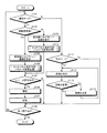
以上の構成を有する撮像装置1が行う動作について説明する。図4は、撮像装置1の処理を示すフローチャートである。
An operation performed by the
図4に示すように、撮像装置1が撮影モードに設定されている場合(ステップS101:Yes)について説明する。この場合、制御部214は、接眼部4が有効であるか否かを判断する(ステップS102)。具体的には、制御部214は、接眼部4の電源スイッチ(図示せず)がオン状態であるか、またはユーザが接触センサ(図示せず)に接触することにより接触センサから検出信号が出力されているか否かを判断することにより、接眼部4が有効であるか否かを判断する。接眼部4が有効であると制御部214が判断した場合(ステップS102:Yes)、撮像装置1は、後述するステップS103へ移行する。一方、接眼部4が有効でないと制御部214が判断した場合(ステップS102:No)、撮像装置1は、後述するステップS109へ移行する。
As shown in FIG. 4, the case where the
ステップS103において、表示制御部214gは、撮像素子203が連続的に生成する画像データに対応するライブビュー画像を接眼表示部42および表示部211にそれぞれ順次表示させる。
In step S103, the
続いて、撮像装置1は、タッチパネル212に対して行われるタッチ操作の判定を行い、この判定結果に基づいて、撮像装置1の撮影条件および接眼部4が表示する表示画像のパラメータを変更するタッチパネル操作判定・パラメータ変更処理1を実行する(ステップS104)。なお、タッチパネル操作判定・パラメータ変更処理1の詳細については後述する。
Subsequently, the
その後、レリーズスイッチ210bから2ndレリーズ信号が入力された場合(ステップS105:Yes)、撮影制御部214fは、静止画撮影を行い(ステップS106)、撮像した画像データを記憶部213に記憶する(ステップS107)。
Thereafter, when a 2nd release signal is input from the
続いて、制御部214は、終了操作が行われたか否かを判断する(ステップS108)。具体的には、制御部214は、電源スイッチ210aが操作されることにより、撮像装置1の電源がオフ状態になったか否かを判断することにより、終了操作が行われたか否かを判断する。終了操作が行われたと制御部214が判断した場合(ステップS108:Yes)、本処理を終了する。一方、終了操作が行われていないと制御部214が判断した場合(ステップS108:No)、撮像装置1は、ステップS101へ戻る。
Subsequently, the control unit 214 determines whether or not an end operation has been performed (step S108). Specifically, the control unit 214 determines whether or not the end operation has been performed by determining whether or not the power of the
ステップS105において、レリーズスイッチ210bを介して2ndレリーズ信号が入力されていないと制御部214が判断した場合(ステップS105:No)、撮像装置1は、ステップS108へ移行する。
In step S105, when the control unit 214 determines that the 2nd release signal is not input via the
ステップS109において、表示制御部214gは、撮像素子203が連続的に生成する画像データに対応するライブビュー画像を表示部211に順次表示させる。
In step S109, the
続いて、撮像装置1は、タッチパネル212に対して行われるタッチ操作の判定を行い、この判定結果に基づいて撮像装置1の撮影条件および表示部211の表示画像のパラメータを変更するタッチパネル操作判定・パラメータ変更処理2を実行する(ステップS110)。なお、タッチパネル操作判定・パラメータ変更処理2の詳細については後述する。その後、撮像装置1は、ステップS105へ移行する。
Subsequently, the
つぎに、撮像装置1が撮影モードに設定されていない場合(ステップS101:No)について説明する。この場合、制御部214は、撮像装置1が記憶部213に記憶された画像データを再生する再生モードに設定されているか否かを判断する。撮像装置1が再生モードに設定されていると制御部214が判断した場合(ステップS111:Yes)、撮像装置1は、ステップS112へ移行する。一方、撮像装置1が再生モードに設定されていないと制御部214が判断した場合(ステップS111:No)、撮像装置1は、ステップS108へ戻る。
Next, a case where the
続いて、表示制御部214gは、記憶部213が記憶する画像データに対応する画像を表示部211へ表示させる(ステップS112)。
Subsequently, the
その後、切替スイッチ(図示せず)から画像の変更を指示する切替信号が入力された場合(ステップS113:Yes)、表示制御部214gは、表示部211が表示する画像を変更する(ステップS114)。ステップS114の後、撮像装置1は、ステップS112へ戻る。一方、切替信号が入力されていない場合(ステップS113:No)、撮像装置1は、ステップS108へ戻る。
Thereafter, when a switching signal for instructing image change is input from a changeover switch (not shown) (step S113: Yes), the
つぎに、図4のステップS104で説明したタッチパネル操作判定・パラメータ変更処理1について説明する。なお、以下においては、まず、本実施の形態1にかかるタッチパネル操作判定・パラメータ変更処理1の概要について説明する。その後、タッチパネル操作判定・パラメータ変更処理1について詳細に説明する。
Next, the touch panel operation determination /
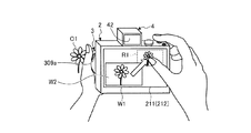
図5は、ユーザが接眼部4で被写体O1(花)に対するピント状態を確認しながら撮影を行う際の状況を示す図である。図6は、図5に示す状況下でユーザが表示部211によって表示されるライブビュー画像内において所望の被写体O1に対してタッチする際の状況を模式的に示す図である。図7は、図5に示す状況下で接眼部4が連続的に表示する画像の一例を示す図である。
FIG. 5 is a diagram illustrating a situation when the user performs shooting while confirming the focus state with respect to the subject O1 (flower) with the
図5および図6に示すように、ユーザは、撮像装置1の本体部2とレンズ部3とに対してホールディングした状態から、手ブレを防止するため、極力、指や手を動かさないで必要な撮影操作、たとえば被写体O1のピント状態の確認およびレンズ部3のピント変更操作等を敏速かつ容易に行いたい。また、図6に示すように、ユーザは、親指でタッチパネル212上をタッチできる領域が狭いうえ、表示部211を見ることなく、接眼部4を覗きこんでいる場合が多い。このため、本実施の形態1にかかるタッチパネル操作判定・パラメータ変更処理1では、ユーザが撮像装置1をホールディングした状態から右手の親指で操作可能な領域をタッチパネル212の有効領域として設定するようにしてもよい。もちろん、ダイレクトにタッチする制御にしてもよい。
As shown in FIGS. 5 and 6, the user needs to move the fingers and hands as much as possible in order to prevent camera shake from being held with respect to the
また、ユーザは、右手の人差し指をレリーズスイッチ210bにおいたまま、左手でレンズ部3を保持しつつ、被写体O1のピント状態の確認を行いたい。そこで、本実施の形態1にかかるタッチパネル操作判定・パラメータ変更処理1では、ユーザが被写体O1のピント状態を接眼部4の接眼表示部42で確認することができるように、ユーザが右手の親指でタッチパネル212を介して表示部211によって表示されているライブビュー画像W1の被写体O1にタッチした場合、そのタッチ位置を含む対象領域R1をトリミング部214dが切出して拡大画像W2を生成し、この拡大画像W2を表示制御部214gが接眼表示部42に表示させる(図7)。その後、パラメータ変更部214eは、リング309aの操作に応じて、レンズ制御部312を介してフォーカスレンズ駆動部304を駆動させることにより、拡大画像W2およびライブビュー画像W1に含まれる被写体O1に対するレンズ部3のピント(フォーカス)を変更する。また、図5〜図7においては、被写体O1に対するピント状態の調整であったが、ユーザがリング309aを操作することにより、被写体O1の拡大または縮小の調整を行ってもよい。この場合、パラメータ変更部214eは、リング309aの操作に応じて、レンズ制御部312を介してズームレンズ駆動部302を駆動させることにより、拡大画像W2およびライブビュー画像W1に含まれる被写体O1に対する倍率を変更する。さらに、図7において、表示制御部214gは、撮像装置1の撮影パラメータに関する情報として拡大または縮小中であることを示すアイコンを表示部211に表示させてもよい。
Further, the user wants to check the focus state of the subject O1 while holding the
このように、本実施の形態1にかかるタッチパネル操作判定・パラメータ変更処理1では、ユーザが撮像装置1に対してホールディングした状態を維持したまま、目視で困難な被写体O1のピントに対する確認を行いながら、リング309aを操作することで被写体O1に対するレンズ部3のピント位置(フォーカス位置)の変更を簡単に行うことができる。なお、本実施の形態1では、有効領域を適宜設定することができる。さらに、図7の拡大画像W2において、表示制御部214gは、撮像装置1の撮影モードに関する情報としてアイコンA1を接眼表示部42に表示させてもよい。アイコンA1は、撮像装置1がマニュアルフォーカスモードに設定されていることを示すアイコンである。
As described above, in the touch panel operation determination /
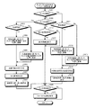
図8は、タッチパネル操作判定・パラメータ変更処理1の概要を示すフローチャートである。
FIG. 8 is a flowchart showing an overview of touch panel operation determination /
図8に示すように、制御部214は、ユーザがタッチパネル212に対してタッチを継続しているか否かを判断する(ステップS201)。具体的には、制御部214は、タッチパネル212から位置信号が出力されているか否かを判断することにより、ユーザがタッチパネル212に対してタッチを継続しているか否かを判断する。ユーザがタッチパネル212に対してタッチを継続していると制御部214が判断した場合(ステップS201:Yes)、撮像装置1は、後述するステップS211へ移行する。一方、ユーザがタッチパネル212に対してタッチを継続していないと制御部214が判断した場合(ステップS201:No)、撮像装置1は、後述するステップS202へ移行する。
As illustrated in FIG. 8, the control unit 214 determines whether or not the user continues to touch the touch panel 212 (step S201). Specifically, the control unit 214 determines whether or not the user continues to touch the
ステップS202において、制御部214は、タッチパネル212がタッチを検出したか否かを判断する。具体的には、制御部214は、タッチパネル212から位置信号が出力されたか否かを判断する。タッチパネル212がタッチを検出したと制御部214が判断した場合(ステップS202:Yes)、撮像装置1は、後述するステップS203へ移行する。一方、タッチパネル212がタッチを検出していないと制御部214が判断した場合(ステップS202:No)、撮像装置1は、後述するステップS216へ移行する。
In step S202, the control unit 214 determines whether or not the
ステップS203において、制御部214は、ユーザがタッチパネル212にタッチしたタッチ位置が有効領域(図6を参照)であるか否かを判断する。ユーザがタッチパネル212にタッチしたタッチ位置が有効領域であると制御部214が判断した場合(ステップS203:Yes)、撮像装置1は、ステップS204へ移行する。一方、ユーザがタッチパネル212にタッチしたタッチ位置が有効領域でないと制御部214が判断した場合(ステップS203:No)、撮像装置1は、ステップS205へ移行する。
In step S <b> 203, the control unit 214 determines whether or not the touch position where the user touches the
ステップS204において、タッチ位置検出部214cは、ユーザがタッチパネル212の有効領域にタッチしたタッチ位置を撮像素子203の位置(座標)に換算する。
In step S <b> 204, the touch position detection unit 214 c converts the touch position where the user touches the effective area of the
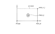
図9は、タッチ位置検出部214cがタッチパネル212の有効領域におけるタッチ位置を撮像素子203上の位置に換算する際の換算方法を模式的に説明する図である。図9において、タッチパネル212の左下を原点P1とし、タッチパネル212の横方向をX軸とし、タッチパネル212の縦方向をY軸とする座標系として考える。また、撮像素子203の撮像領域において左下を原点とし、撮像素子203の横方向をX軸とし、撮像素子203の縦方向をY軸とする座標系として考える。
FIG. 9 is a diagram schematically illustrating a conversion method when the touch position detection unit 214 c converts the touch position in the effective area of the
図9に示すように、タッチ位置検出部214cは、タッチパネル212の右下の点P2の座標を(X1,0)、有効領域R11の左上の点P3の座標を(X0,Y0)、タッチ位置P4の座標を(Xf,Yf)、撮像素子203の撮像領域の右上の点を(Xi1,Yi1)としたとき、以下の式によってタッチ位置を撮像素子203上の位置(Xif,Yif)に換算する。
Xf:Xif=(X1−X0):Xi1 ・・・(1)
したがって、
Xif=Xi1×Xf/(X1−X0) ・・・(2)
になる。同様に、
Yf:Yif=Y0:Yi1 ・・・(3)
したがって、
Yif=Yi1×(Yf/Y0) ・・・(4)
になる。このように、タッチ位置検出部214cは、式(2)および式(4)を用いて、ユーザがタッチパネル212の有効領域R11においてタッチしたタッチ位置を撮像素子203上の位置(座標)に換算する。
As shown in FIG. 9, the touch position detection unit 214c sets the coordinates of the lower right point P2 of the
X f: X if = (X 1 -X 0): X i1 ··· (1)
Therefore,
X if = X i1 × X f / (X 1 −X 0 ) (2)
become. Similarly,
Y f : Y if = Y 0 : Y i1 (3)
Therefore,
Y if = Y i1 × (Y f / Y 0 ) (4)
become. As described above, the touch position detection unit 214c converts the touch position touched by the user in the effective region R11 of the
図8に戻り、ステップS205において、タッチ位置検出部214cは、ユーザがタッチパネル212にタッチしたタッチ位置を撮像素子203上の位置に換算する。
Returning to FIG. 8, in step S <b> 205, the touch position detection unit 214 c converts the touch position where the user touches the
図10は、タッチ位置検出部214cがタッチパネル212のタッチ位置を撮像素子203上の位置に換算する際の換算方法を模式的に説明する図である。図10において、タッチパネル212の左下を原点P1とし、タッチパネル212の横方向をX軸とし、タッチパネルの縦方向をY軸とする座標系として考える。また、撮像素子203の左下を原点とし、撮像素子203の横方向をX軸とし、撮像素子203の縦方向をY軸とする座標系として考える。
FIG. 10 is a diagram schematically illustrating a conversion method when the touch position detection unit 214 c converts the touch position on the
図10に示すように、タッチ位置検出部214cは、タッチパネル212の右下の点P2の座標を(X1,0)、タッチパネル212の右上の点P5の座標を(X1,Y1)、タッチ位置P4の座標を(Xf,Yf)、撮像素子203の右上の点を(Xi1,Yi1)としたとき、以下の式によってタッチ位置を撮像素子203上の位置(Xif,Yif)に換算する。
Xf:Xif=X1:Xi1 ・・・(5)
したがって、
Xif=Xi1×(Xf/X1) ・・・(6)
になる。同様に、
Yf:Yif=Y1:Yi1 ・・・(7)
したがって、
Yif=Yi1×(Yf/Y1) ・・・(8)
になる。このように、タッチ位置検出部214cは、式(6)および式(8)を用いて、ユーザがタッチパネル212をタッチしたタッチ位置を撮像素子203上の位置(座標)に換算する。
As illustrated in FIG. 10, the touch position detection unit 214c sets the coordinates of the lower right point P2 of the
X f : X if = X 1 : X i1 (5)
Therefore,
X if = X i1 × (X f / X 1 ) (6)
become. Similarly,
Y f : Y if = Y 1 : Y i1 (7)
Therefore,
Y if = Y i1 × (Y f / Y 1 ) (8)
become. As described above, the touch position detection unit 214c converts the touch position at which the user touches the
図8に戻り、ステップS206において、表示制御部214gは、タッチ位置検出部214cが換算した位置に基づいて、対象領域の枠を表示部211に表示させる。具体的には、図6に示すように、表示制御部214gは、タッチ位置検出部214cが換算した換算位置を含む対象領域に対応する枠R1を表示部211に表示させる。これにより、ユーザは、タッチしたタッチ領域を直感的に把握することができる。
Returning to FIG. 8, in step S206, the
続いて、トリミング部214dは、ライブビュー画像から対象領域R1を切り出して拡大画像を生成する(ステップS207)。
Subsequently, the
その後、表示制御部214gは、トリミング部214dが生成した拡大画像を接眼表示部42に表示させる(ステップS208)。
Thereafter, the
続いて、制御部214は、ユーザがリング309aを操作したか否かを判断する(ステップS209)。具体的には、制御部214は、ユーザがリング309aを左右どちらか一方に回転させる操作を行うことにより、リング309aからレンズ部3のフォーカス位置および/またはフォーカス距離の変更を指示する指示信号が入力されたか否かを判断する。ユーザがリング309aを操作したと制御部214が判断した場合(ステップS209:Yes)、撮像装置1は、ステップS210へ移行する。一方、ユーザがリング309aを操作していないと制御部214が判断した場合(ステップS209:No)、撮像装置1は、図4のメインルーチンへ戻る。
Subsequently, the control unit 214 determines whether or not the user has operated the
ステップS210において、パラメータ変更部214eは、リング309aから入力される指示信号に基づいて、レンズ部3のフォーカス位置を変更する。具体的には、パラメータ変更部214eは、リング309aから入力される指示信号に基づいて、本体通信部208およびレンズ通信部311を介してレンズ制御部312に、フォーカスレンズ駆動部304を駆動させてフォーカスレンズ301bを光軸L上に沿って移動させることにより、レンズ部3のフォーカス位置を変更させる駆動信号を出力する。これにより、拡大画像に含まれる被写体のピント状態が変化することにより、ユーザが所望するピント状態になる。なお、フォーカス位置には、レンズ部3のフォーカス位置(ピント位置)およびピント距離(合焦距離)が含まれる。その後、撮像装置1は、図4のメインルーチンへ戻る。
In step S210, the parameter changing unit 214e changes the focus position of the
ステップS211において、制御部214は、ユーザがタッチパネル212にタッチしたタッチ位置が有効領域であるか否かを判断する。ユーザがタッチパネル212にタッチしたタッチ位置が有効領域であると制御部214が判断した場合(ステップS211:Yes)、撮像装置1は、ステップS212へ移行する。一方、ユーザがタッチパネル212にタッチしたタッチ位置が有効領域でないと制御部214が判断した場合(ステップS211:No)、撮像装置1は、ステップS213へ移行する。
In step S211, the control unit 214 determines whether or not the touch position where the user touches the
ステップS212およびステップS213は、上述したステップS204およびステップS205それぞれに対応する。 Step S212 and step S213 correspond to step S204 and step S205 described above, respectively.
続いて、トリミング部214dは、タッチ位置検出部214cが換算した換算位置に基づいて、タッチ位置を含む対象領域をライブビュー画像から切出して拡大した拡大画像を生成する(ステップS214)。
Subsequently, the
その後、表示制御部214gは、トリミング部214dが生成した拡大画像を接眼表示部42に表示させる(ステップS215)。これにより、図5〜図7に示すように、ユーザは、右手の人差し指をレリーズスイッチ210bにおいたまま、左手でレンズ部3のリング309aを操作して、接眼部4の接眼表示部42で拡大画像W2を確認しながら所望の被写体O1に対してレンズ部3のピント調整を容易かつ敏速に行うことができる。ステップS215の後、撮像装置1は、ステップS209へ移行する。
Thereafter, the
ステップS216において、制御部214は、接眼表示部42がトリミング部214dによって連続的に生成された拡大画像を表示しているか否かを判断する。接眼表示部42がトリミング部214dによって連続的に生成された拡大画像を表示していると制御部214が判断した場合(ステップS216:Yes)、撮像装置1は、ステップS217へ移行する。一方、接眼表示部42がトリミング部214dによって連続的に生成された拡大画像を接眼表示部42に表示していないと制御部214が判断した場合(ステップS216:No)、撮像装置1は、ステップS209へ移行する。
In step S216, the control unit 214 determines whether or not the
ステップS217において、表示制御部214gは、接眼表示部42が表示する拡大画像の表示を終了する。その後、撮像装置1は、ステップS209へ移行する。
In step S217, the
つぎに、図4のステップS110のタッチパネル操作判定・パラメータ変更処理2について説明する。なお、以下においては、まず、本実施の形態1にかかるタッチパネル操作判定・パラメータ変更処理2の概要について説明する。その後、タッチパネル操作判定・パラメータ変更処理2について詳細に説明する。
Next, touch panel operation determination /
図11は、ユーザが表示部211で被写体O1に対するピント状態を確認しながら撮影を行う際の状況を示す図である。図12は、図11に示す状況下で表示部211によって表示されるライブビュー画像内において所望の被写体O1に対してタッチする際の状況を模式的に示す図である。
FIG. 11 is a diagram illustrating a situation when the user performs shooting while confirming the focus state with respect to the subject O1 on the
図11および図12に示すように、ユーザは、右手の人差し指をレリーズスイッチ210bにおいたまま、左手でレンズ部3を保持しつつ、被写体O1に対するピント状態の確認を行いたい。そこで、本実施の形態1にかかるタッチパネル操作判定・パラメータ変更処理2では、ユーザが被写体O1のピント状態を表示部211で確認することができるように、ユーザが右手の親指でタッチパネル212を介して表示部211によって表示されているライブビュー画像W1の被写体O1にタッチした場合(図12(a)を参照)、そのタッチ位置を含む対象領域R1をトリミング部214dが切出して拡大画像W2を生成し、この拡大画像W2を表示制御部214gが表示部211の左上画面に表示させる(図12(b))。その後、パラメータ変更部214eは、リング309aの操作に応じて、ライブビュー画像W1内に写る被写体O1に対するレンズ部3のピント(フォーカス)を変更する(図12(c))。これにより、拡大画像W2に含まれる被写体O1のピント状態を変更することができる。なお、パラメータ変更部214eは、リング309aの操作に応じて、ライブビュー画像W1または拡大画像W2内に写る被写体O1の倍率を変更してもよい。
As shown in FIGS. 11 and 12, the user wants to confirm the focus state with respect to the subject O1 while holding the
このように、本実施の形態1にかかるタッチパネル操作判定・パラメータ変更処理2では、ユーザが撮像装置1に対してホールディングした状態を維持したまま、目視で困難な被写体O1に対するピント状態の確認を行いながら、リング309aを操作することで被写体O1に対するレンズ部3のピント位置の変更を容易に行うことができる。さらに、ユーザが拡大画像W2の表示位置を右手で隠れない位置に表示するので、タッチした部分が見えなくなることを防止することができる。なお、拡大画像の表示位置は、適宜設定することができる。さらに、表示制御部214gは、撮像装置1の撮影モードに関する情報としてアイコンA1を表示部211に表示させてもよい。アイコンA1は、撮像装置1がマニュアルフォーカスモードに設定されていることを示すアイコンである。
As described above, in the touch panel operation determination /
図13は、タッチパネル操作判定・パラメータ変更処理2の概要を示すフローチャートである。
FIG. 13 is a flowchart showing an outline of touch panel operation determination /
図13に示すように、制御部214は、ユーザがタッチパネル212に対してタッチを継続しているか否かを判断する(ステップS301)。ユーザがタッチパネル212に対してタッチを継続していると制御部214が判断した場合(ステップS301:Yes)、撮像装置1は、後述するステップS307へ移行する。一方、ユーザがタッチパネル212に対してタッチを継続していないと制御部214が判断した場合(ステップS301:No)、撮像装置1は、後述するステップS302へ移行する。
As illustrated in FIG. 13, the control unit 214 determines whether or not the user continues to touch the touch panel 212 (step S301). When the control unit 214 determines that the user continues to touch the touch panel 212 (step S301: Yes), the
ステップS302において、制御部214は、タッチパネル212がタッチを検出したか否かを判断する。タッチパネル212がタッチを検出したと制御部214が判断した場合(ステップS302:Yes)、撮像装置1は、後述するステップS303へ移行する。一方、タッチパネル212がタッチを検出していないと制御部214が判断した場合(ステップS302:No)、撮像装置1は、後述するステップS311へ移行する。
In step S302, the control unit 214 determines whether or not the
ステップS303において、タッチ位置検出部214cは、ユーザがタッチパネル212にタッチしたタッチ位置を撮像素子203の座標に換算する。具体的には、タッチ位置検出部214cは、式(6)および式(8)を用いて、ユーザがタッチパネル212にタッチしたタッチ位置を撮像素子203上の位置(座標)に換算する。
In step S <b> 303, the touch position detection unit 214 c converts the touch position where the user touches the
続いて、表示制御部214gは、タッチ位置検出部214cが換算した換算位置に基づいて、タッチ位置を含む対象領域の枠R1を表示部211に表示させる(ステップS304)。これにより、ユーザは、タッチしたタッチ領域を直感的に把握することができる。
Subsequently, the
ステップS305およびステップS306は、図8のステップS209およびステップS210にそれぞれ対応する。その後、撮像装置1は、図4のメインルーチンへ戻る。
Step S305 and step S306 correspond to step S209 and step S210 in FIG. 8, respectively. Thereafter, the
ステップS307において、制御部214は、ユーザがタッチ位置を表示部211の右下に向けてスライドしているか否かを判断する。具体的には、制御部214は、タッチパネル212から出力される位置信号に基づいて、タッチ位置検出部214cが換算した撮像素子203上の座標のXの値が増加し、Yの値が減少しているか否かを判断することにより、ユーザがタッチ位置を表示部211の右下に向けてスライドしているか否かを判断する。ユーザがタッチ位置を表示部211の右下に向けてスライドしていると制御部214が判断した場合(ステップS307:Yes)、撮像装置1は、ステップS308へ移行する。一方、ユーザがタッチ位置を表示部211の右下に向けてスライドしていないと制御部214が判断した場合(ステップS307:No)、撮像装置1は、ステップS305へ移行する。
In step S <b> 307, the control unit 214 determines whether the user is sliding the touch position toward the lower right of the
ステップS308において、制御部214は、現在のタッチ継続位置が表示部211の右下画面の縦横1/3以内であるか否かを判断する。現在のタッチ継続位置が表示部211の右下画面の縦横1/3以内であると制御部214が判断した場合(ステップS308:Yes)、撮像装置1は、ステップS309へ移行する。一方、現在のタッチ継続位置が右下画面の縦横1/3以内でないと制御部214が判断した場合(ステップS308:No)、撮像装置1は、ステップS305へ移行する。
In step S <b> 308, the control unit 214 determines whether or not the current touch continuation position is within 1/3 vertical and horizontal of the lower right screen of the
ステップS309において、トリミング部214dは、ライブビュー画像からタッチ位置を含む対象領域R1を切出して拡大画像を生成する。
In step S309, the
続いて、表示制御部214gは、トリミング部214dが生成した拡大画像を、表示部211の左上画面の縦横2/3分の表示領域上に表示させる(ステップS310)。これにより、ユーザは、表示部211が表示する所望の被写体O1が拡大された拡大画像を見ながら、リング309aを操作することによって、レンズ部3のピントを手動で変更することにより、被写体O1に対するピント状態を調整することができる。
Subsequently, the
ステップS311およびステップS312は、図8のステップS216およびステップS217にそれぞれ対応する。 Step S311 and step S312 correspond to step S216 and step S217 in FIG. 8, respectively.
以上説明した本発明の実施の形態1によれば、トリミング部214dがタッチパネル212から出力される位置信号に基づいて、撮像素子203によって生成された画像データに対応する画像からタッチ位置を含む領域を切出して拡大画像を生成し、表示制御部214gが拡大画像を接眼表示部42に表示させる。この結果、ユーザは、接眼表示部42で被写体のピント状態を確認しながら、被写体に対するピント操作を容易に変更することができる。
According to the first embodiment of the present invention described above, the region including the touch position from the image corresponding to the image data generated by the
また、本発明の実施の形態1によれば、トリミング部214dがタッチパネル212から出力される位置信号に基づいて、撮像素子203によって生成された画像データからタッチ位置を含む領域を切出して拡大画像データを生成し、表示制御部214gがトリミング部214dによって生成されたトリミング画像データに対応するトリミング画像をライブビュー画像に重畳して表示部211に表示させるとともに、タッチパネル212から出力される位置信号の変化に応じて、トリミング画像の表示態様を制御する。この結果、ユーザは、拡大画像を確認することで、被写体に対するピント操作を容易に変更することができる。
Further, according to
また、本発明の実施の形態1によれば、パラメータ変更部214eがレンズ操作部309のリング309aの操作に応じて、ズームレンズ301aまたはフォーカスレンズ301bを駆動する駆動信号をレンズ制御部312に出力することにより、拡大画像の表示領域サイズまたは拡大画像に含まれる被写体の表示倍率を変更する。この結果、ユーザは、ピント操作またはズーム操作を行いながら、所望の被写体のピント状態または拡大率を容易に調整することができる。
Further, according to
なお、本発明の実施の形態1では、パラメータ変更部214eがリング309aの操作に応じて、レンズ部3のピント状態または倍率を変更することにより、拡大画像の表示態様を変更していたが、たとえばシャッタ速度、撮影感度(ISO感度)、露出時間を変更することにより、拡大画像の表示態様を変更してもよい。
In the first embodiment of the present invention, the parameter changing unit 214e changes the display state of the enlarged image by changing the focus state or magnification of the
また、本発明の実施の形態1によれば、表示制御部214gがトリミング部214dによって生成された拡大画像を表示部211の左上画面の縦横2/3分の表示領域上に表示させていたが、たとえば拡大画像を表示部211の左下画面の縦横2/3分の表示領域上に表示させてもよい。さらに、表示制御部214gは、タッチパネル212から出力される位置信号に応じて、拡大画像を表示する表示位置を適宜変更してもよい。
Further, according to
(実施の形態1の変形例1)
上述した実施の形態1において、撮像装置1が実行するタッチパネル操作判定・パラメータ変更処理2の内容を変更することも可能である。このため、以下においては、まず、本実施の形態1の変形例1にかかる撮像装置1が実行するタッチパネル操作判定・パラメータ変更処理2の概要について説明する。その後、本実施の形態1の変形例1にかかるタッチパネル操作判定・パラメータ変更処理2について詳細に説明する。
(
In the first embodiment described above, the content of the touch panel operation determination /
図14は、本実施の形態1の変形例1にかかる撮像装置1が実行するタッチパネル操作判定・パラメータ変更処理2を模式的に説明する図である。なお、図14においては、ユーザの左手は、レンズ部3を保持しているものとして説明するが、説明を簡略化するため、図示せずに説明する。
FIG. 14 is a diagram schematically illustrating touch panel operation determination /
図14に示すように、ユーザが右手の親指でタッチパネル212を介して表示部211によって表示されているライブビュー画像W1の被写体O1にタッチした場合(図14(a))、そのタッチ位置を含む対象領域R1をトリミング部214dが切出して拡大画像W2を生成し、この拡大画像W2を表示制御部214gが表示部211の左上画面に表示させる(図14(b))。続いて、パラメータ変更部214eは、ユーザのスライド操作(軌跡)に応じて、拡大画像W2に含まれる被写体(O1)の表示倍率および拡大画像W2の表示領域サイズを変更する。その後、表示制御部214gは、パラメータ変更部214eが変更した拡大画像W2の表示倍率および拡大画像W2の表示領域サイズに基づいて、トリミング部214dが生成した拡大画像W2を表示部211に表示させる(図14(c))。この場合、図14に示すように、パラメータ変更部214eは、ユーザのスライド操作に応じて、トリミング部214dによる対象領域R1(トリミング領域)を徐々に小さくすることにより、拡大画像W2に含まれる被写体O1を仮想的に拡大することができる。さらに、図14において、パラメータ変更部214eは、ユーザのスライド操作に応じて、トリミング部214dによる対象領域R1を徐々に大きくすることにより、拡大画像W2に含まれる被写体O1を仮想的に縮小するようにしてもよい。
As shown in FIG. 14, when the user touches the subject O1 of the live view image W1 displayed on the
このように、本実施の形態1の変形例1にかかる撮像装置1が実行するタッチパネル操作判定・パラメータ変更処理2では、ユーザが撮像装置1に対してホールディングした状態を維持したまま、目視で困難な被写体O1に対するピント状態の確認を行いながら、リング309aを操作することで被写体O1に対するレンズ部3によるピント位置の変更を簡単に行うことができる。さらに、ユーザのスライド操作に応じて、拡大画像W2に含まれる被写体O1の表示倍率および拡大画像W2の表示領域サイズを変更することができるので、被写体O1に対するレンズ部3のピント調整をより精度よく簡易な操作で行うことができる。もちろん、本実施の形態1の変形例1では、トリミング部214dによるトリミング領域そのものは同じのまま、切出して生成した画像(トリミング画像)を拡大または縮小するようにしてもよい。
As described above, in the touch panel operation determination /
図15は、本実施の形態1の変形例1にかかる撮像装置1が実行する図4のステップS110のタッチパネル操作判定・パラメータ変更処理2の概要を示すフローチャートである。
FIG. 15 is a flowchart illustrating an overview of the touch panel operation determination /
図15に示すように、ステップS401〜ステップS406は、図13のステップS301〜ステップS306にそれぞれ対応する。 As shown in FIG. 15, steps S401 to S406 correspond to steps S301 to S306 in FIG. 13, respectively.
ステップS407において、制御部214は、ユーザがタッチ位置を表示部211の右下に向けてスライドしているか否かを判断する。ユーザがタッチ位置を表示部211の右下に向けてスライドしていると制御部214が判断した場合(ステップS407:Yes)、撮像装置1は、ステップS408へ移行する。一方、ユーザがタッチ位置を表示部211の右下に向けてスライドしていないと制御部214が判断した場合(ステップS407:No)、撮像装置1は、ステップS405へ移行する。
In step S407, the control unit 214 determines whether the user is sliding the touch position toward the lower right of the
ステップS408において、制御部214は、ユーザが最初にタッチしたタッチ位置(A点)から現在のタッチ継続位置までのスライド移動距離D1が最初にタッチしたタッチ位置から表示部211の右下部までのスライド限界距離D0の半分以上であるか否かを判断する。スライド移動距離D1がスライド限界距離D0の半分以上であると制御部214が判断した場合(ステップS408:Yes)、撮像装置1は、ステップS409へ移行する。一方、スライド移動距離D1がスライド限界距離D0の半分以上でないと制御部214が判断した場合(ステップS408:No)、撮像装置1は、ステップS405へ移行する。
In step S <b> 408, the control unit 214 determines that the slide movement distance D 1 from the first touch position (point A) touched by the user to the current touch continuation position is from the first touch position to the lower right part of the
図16は、タッチ位置検出部214cがタッチパネル212のタッチ位置を撮像素子203の撮像領域上に換算する際の換算方法を模式的に説明する図である。図16において、タッチパネル212の左下を原点P1とし、タッチパネル212の横方向をX軸とし、タッチパネル212の縦方向をY軸とする座標系として考える。
FIG. 16 is a diagram schematically illustrating a conversion method when the touch position detection unit 214 c converts the touch position of the
図16に示すように、タッチ位置検出部214cは、タッチパネル212の右下の点P2の座標を(X1,0)、タッチパネル212の右上の点P5の座標を(X1,Y1)、最初にタッチしたタッチ位置P4の座標を(Xf1,Yf1)、スライド移動後のタッチ位置P6の座標を(Xf2,Yf2)としたとき、以下の式によってタッチ位置P4から点P2までのスライド限界距離D0およびタッチ位置P1からタッチ継続位置P6までのスライド距離移動D1が算出される。
D0={(X1−Xf1)2+(Yf1)2)}1/2 ・・・(9)
となる。同様に、タッチ位置P1からタッチ継続位置P6のスライド距離D1は、
D1={(Xf2−Xf1)2+(Yf1−Yf2)2}1/2 ・・・(10)
となる。このように、タッチ位置検出部214cは、式(9)および式(10)を用いて、スライド限界距離D0およびスライド移動距離D1を算出する。
As illustrated in FIG. 16, the touch position detection unit 214c sets the coordinates of the lower right point P2 of the
D 0 = {(X 1 −X f1 ) 2 + (Y f1 ) 2 )} 1/2 (9)
It becomes. Similarly, the slide distance D 1 from the touch position P1 to the touch continuation position P6 is
D 1 = {(X f2 −X f1 ) 2 + (Y f1 −Y f2 ) 2 } 1/2 (10)
It becomes. Thus, the touch position detection unit 214c, using Equation (9) and (10), calculates the sliding limit distance D 0 and the slide movement distance D 1.
続いて、パラメータ変更部214eは、タッチ位置検出部214cが算出したスライド距離D1とスライド限界距離D0との比率に基づいて、拡大画像の表示倍率を変更する(ステップS409)。 Subsequently, the parameter changing section 214e based on the ratio between the sliding distance D 1 and the slide limit distance D 0 that touch position detection unit 214c is calculated to change the magnification of the enlarged image (step S409).
図17は、スライド距離D1とスライド限界距離D0との比率と拡大画像の表示倍率との関係を示す図である。図17において、横軸がスライド距離D1とスライド限界距離D0との比率を示し、縦軸が拡大画像の表示倍率を示す。なお、記憶部213は、スライド距離D1とスライド限界距離D0との比率と拡大画像の表示倍率との関係を記憶する。
FIG. 17 is a diagram illustrating the relationship between the ratio of the slide distance D 1 and the slide limit distance D 0 and the display magnification of the enlarged image. 17, the horizontal axis represents the ratio of the slide distance D 1 and the slide limit distance D 0, the vertical axis represents the display magnification of the enlarged image. The
図17の直線L1に示すように、パラメータ変更部214eは、スライド距離D1とスライド限界距離D0との比率に基づいて、拡大画像の表示倍率を変更する。このように、パラメータ変更部214eは、ユーザによるスライド距離D1に基づいて、拡大画像の表示倍率をリニアに変更する。これにより、本実施の形態1の変形例1では、ユーザに対してアナログ的な操作感を提供することができる。なお、図17の曲線C1に示すように、パラメータ変更部214eは、スライド距離D1とスライド限界距離D0との比率が1に近づくにつれ拡大画像の表示倍率を大きく変化させてもよい。これにより、拡大画像の拡大に伴って画質が粗くなることを未然に防止することができる。
As it indicated by the straight line L1 in FIG. 17, the parameter changing section 214e based on the ratio between the sliding distance D 1 and the slide limit distance D 0, to change the magnification of the enlarged image. Thus, the parameter changing section 214e on the basis of the slide distance D 1 by a user, to change the magnification of the enlarged image linearly. Thereby, in the
ステップS409の後、パラメータ変更部214eは、スライド距離D1とスライド限界距離D0との比率に基づいて、拡大画像の表示領域サイズを変更する(ステップS410)。 After step S409, the parameter changing section 214e based on the ratio between the sliding distance D 1 and the slide limit distance D 0, changes the display area size of the enlarged image (step S410).
図18は、スライド距離D1とスライド限界距離D0との比率と拡大画像の表示領域サイズとの関係を示す図である。図18において、横軸がスライド距離D1とスライド限界距離D0との比率を示し、縦軸が拡大画像の表示領域サイズを示す。なお、記憶部213は、スライド距離D1とスライド限界距離D0との比率と拡大画像の表示領域サイズとの関係を記憶する。
FIG. 18 is a diagram showing the relationship between the ratio of the slide distance D 1 and the slide limit distance D 0 and the display area size of the enlarged image. In FIG. 18, the horizontal axis indicates the ratio between the slide distance D 1 and the slide limit distance D 0, and the vertical axis indicates the display area size of the enlarged image. The
図18の直線L11に示すように、パラメータ変更部214eは、スライド距離D1とスライド限界距離D0との比率に基づいて、表示部211で表示する拡大画像の表示領域サイズを決定する。具体的には、パラメータ変更部214eは、スライド距離D1とスライド限界距離D0との比率が1になった場合、表示部211で表示する拡大画像の表示領域サイズを表示部211の画面全域になるように拡大画像の表示領域サイズを変更する。これにより、パラメータ変更部214eは、ユーザによるスライド距離D1に基づいて、拡大画像の表示領域サイズを徐々に変更するので、ユーザに対してアナログ的な操作感を提供することができる。
As indicated by the straight line L11 in FIG. 18, the parameter changing section 214e based on the ratio between the sliding distance D 1 and the slide limit distance D 0, determines the display area size of the enlarged image displayed on the
続いて、トリミング部214dは、パラメータ変更部214eが設定した表示倍率および表示領域サイズに基づいて、タッチ位置を含む対象領域を切出して拡大画像を生成する(ステップS411)。
Subsequently, the
その後、表示制御部214gは、表示部211の画面左上にトリミング部214dが生成した拡大画像を表示させる(ステップS412)。これにより、ユーザは、アナログ的な操作感で所望の被写体のピント状態を確認することができるとともに、拡大画像の表示倍率および表示領域サイズを簡易な操作で調整することができる。ステップS412の後、撮像装置1は、ステップS405へ移行する。
Thereafter, the
ステップS413およびステップS414は、図13のステップS311およびステップS312にそれぞれ対応する。 Step S413 and step S414 correspond to step S311 and step S312 of FIG. 13, respectively.
以上説明した本発明の実施の形態1の変形例1によれば、ユーザが所望する被写体のピント確認用の拡大画像の表示領域を移動させることができるとともに、表示領域のサイズを変更することができる。この結果、ユーザは、撮像装置1をホールディングした状態から直感的に所望の被写体のピンチを把握することができるとともに、リング309aを操作することで被写体にピントを容易かつ敏速に合わせることができる。
According to the first modification of the first embodiment of the present invention described above, the display area of the enlarged image for confirming the focus of the subject desired by the user can be moved and the size of the display area can be changed. it can. As a result, the user can intuitively grasp the pinch of a desired subject from the state in which the
なお、本実施の形態1の変形例1にかかるタッチパネル操作判定・パラメータ変更処理2では、ユーザがスライド操作を表示部211の左上から右下に向けて移動させていたが、たとえば図19に示すように、ユーザがスライド操作を表示部211の左下から右上に向けて移動した場合であっても適用することができる。
In the touch panel operation determination /
また、本実施の形態1の変形例1では、パラメータ214eがユーザによるスライド操作に応じて、拡大画像に含まれる被写体の表示倍率および拡大画像の表示領域サイズを変更していたが、たとえばユーザによるスライド操作に応じて、トリミング部214dによるトリミング領域を拡大または縮小してもよい。これにより、拡大画像に含まれる被写体を擬似的に拡大または縮小することができる。
In the first modification of the first embodiment, the parameter 214e changes the display magnification of the subject included in the enlarged image and the display area size of the enlarged image according to the slide operation by the user. Depending on the slide operation, the trimming region by the
(実施の形態1の変形例2)
上述した実施の形態1において、撮像装置1が実行するタッチパネル操作判定・パラメータ変更処理2の内容をさらに変更することも可能である。
(
In the first embodiment described above, it is possible to further change the content of the touch panel operation determination /
図20は、本実施の形態1の変形例2にかかる撮像装置1が実行する図4のステップS110のタッチパネル操作判定・パラメータ変更処理2の概要を示すフローチャートである。
FIG. 20 is a flowchart showing an overview of the touch panel operation determination /
図20に示すように、ステップS501〜ステップS507は、図13のステップS301〜ステップS307にそれぞれ対応する。 As shown in FIG. 20, steps S501 to S507 correspond to steps S301 to S307 in FIG. 13, respectively.
ステップS508において、制御部214は、ユーザが最初にタッチしたタッチ位置から現在のタッチ継続位置が表示部211の表示画面における右下画面縦横1/3以内であるか否かを判断する。ユーザが最初にタッチしたタッチ位置から現在のタッチ継続位置が表示部211の表示画面における右下画面縦横1/3以内であると制御部214が判断した場合(ステップS508:Yes)、撮像装置1は、ステップS509へ移行する。一方、ユーザが最初にタッチしたタッチ位置から現在のタッチ継続位置が表示部211の表示画面における右下画面縦横1/3以内でないと制御部214が判断した場合(ステップS508:No)、撮像装置1は、ステップS505へ移行する。ここで、画面縦横1/3にした理由は、タッチ選択した部分を画面縦横1/3の部分までシフト操作した時、残りの画面縦横2/3の部分が画像の表示部分になるが、ここに拡大した場合に、十分な拡大エリアが得られるからである。たとえば、タッチした部分を中心に画面の縦横1/3の画像をユーザが選択した場合、まず、2倍の拡大が可能になるからである。また、さらに拡大したい場合、この右下画面縦横1/3のエリアを利用して、指を動かすことによって、さらに大きく拡大する仕様において、十分な操作分解能での操作が可能となる。この領域が狭いと、指の震えに敏感になって、少しの動きで拡大率が変化してちらついてしまうような不具合となる。
In step S508, the control unit 214 determines whether or not the current touch continuation position is within 1/3 of the lower right screen vertical and horizontal directions on the display screen of the
ステップS509において、パラメータ変更部214eは、スライド移動距離D1とスライド限界距離D0との比率に基づいて、拡大画像の拡大率と表示部211の画面明るさとを変更する。
In step S509, the parameter changing section 214e based on the ratio between the sliding distance D 1 and the slide limit distance D 0, changing the magnification of the enlarged image and the screen brightness of the
図21は、スライド距離D1とスライド限界距離D0との比率と拡大画像の表示倍率とのの関係を示す図である。図21において、横軸がスライド距離D1とスライド限界距離D0との比率を示し、縦軸が拡大画像の表示倍率を示す。なお、記憶部213は、スライド距離D1とスライド距離D0との比率と拡大画像の表示倍率との関係を記憶する。
FIG. 21 is a diagram illustrating the relationship between the ratio of the slide distance D 1 and the slide limit distance D 0 and the display magnification of the enlarged image. In Figure 21, the horizontal axis represents the ratio of the slide distance D 1 and the slide limit distance D 0, the vertical axis represents the display magnification of the enlarged image. Note that the
図21の直線L12に示すように、パラメータ変更部214eは、スライド距離D1とスライド限界距離D0との比率に基づいて、拡大画像に含まれる被写体の表示倍率を変更する。さらに、図21に示すように、パラメータ変更部214eは、スライド距離D1とスライド限界距離D0との比率が0.9に到達した時点で拡大画像の表示倍率を最高倍率(8倍)に変更する。この場合、パラメータ変更部214eは、スライド距離D1とスライド限界距離D0との比率が0.9を超えた時点から表示部211が表示するライブビュー画像および拡大画像の明るさのパラメータを変更する。具体的には、パラメータ変更部214eは、ライブビュー画像および拡大画像の明るさ情報、たとえば輝度情報、コントラストおよび色情報を変更する。これにより、ライブビュー画像および拡大画像の視認性が向上する。この結果、ユーザが外光の影響で表示部211が表示するライブビュー画像や拡大画像が見えなくなることを確実に防止することができる。さらに、パラメータ変更部214eは、スライド距離D1とスライド限界距離D0との比率が0.9を超えた時点で表示部211が表示するライブビュー画像および拡大画像の明るさ(を最大値に変更してもよい。また、パラメータ変更部214eは、スライド距離D1とスライド限界距離D0との比率が0.9を超えた場合、電池(図示せず)の残量に応じて、表示部211の明るさを適宜変更するようにしてもよい。
As indicated by the straight line L12 in FIG. 21, the parameter changing section 214e based on the ratio between the sliding distance D 1 and the slide limit distance D 0, to change the magnification of an object included in the enlarged image. Furthermore, as shown in FIG. 21, the parameter changing unit 214e is to slide a distance D 1 and the slide limit distance D 0 between the highest magnification the magnification of the enlarged image when the ratio reaches 0.9 (8-fold) change. In this case, the parameter changing unit 214e may change the brightness parameters of the live view image and enlarged image ratio of the slide distance D 1 and the slide limit distance D 0 is displayed the
ステップS509の後、トリミング部214dは、パラメータ変更部214eが設定した表示倍率に基づいて、タッチ位置を含む対象領域を切出して拡大画像を生成する(ステップS510)。
After step S509, the
続いて、表示制御部214gは、表示部211の表示画面の画面左上の縦横2/3分の表示領域に、トリミング部214dが生成した拡大画像を表示部211に表示させ(ステップS511)、パラメータ変更部214eによって変更された明るさのパラメータに、表示部211の表示画面の明るさを変更する(ステップS512)。その後、撮像装置1は、ステップS505へ移行する。
Subsequently, the
ステップS513およびステップS514は、図13のステップS311およびステップS312にそれぞれ対応する。 Step S513 and step S514 correspond to step S311 and step S312 of FIG. 13, respectively.
以上説明した本実施の形態1の変形例2によれば、パラメータ変更部214eがタッチパネル212から出力される位置信号の変化に基づいて、拡大画像に含まれる被写体の倍率を変更するとともに、表示部211が表示するライブビュー画像および拡大画像の明るさのパラメータを変更する。この結果、外光の影響で表示部211が表示するライブビュー画像や拡大画像が見えなくなることを防止することができる。
According to the second modification of the first embodiment described above, the parameter changing unit 214e changes the magnification of the subject included in the enlarged image based on the change in the position signal output from the
(実施の形態1の変形例3)
上述した実施の形態1において、撮像装置1が実行するタッチパネル操作判定・パラメータ変更処理2の内容をさらに変更することも可能である。
(
In the first embodiment described above, it is possible to further change the content of the touch panel operation determination /
図22は、本実施の形態1の変形例3にかかる撮像装置1が実行する図4のステップS110のタッチパネル操作判定・パラメータ変更処理2の概要を示すフローチャートである。
FIG. 22 is a flowchart illustrating an overview of the touch panel operation determination /
図22に示すように、ステップS601〜ステップS603は、図13のステップS301〜ステップS303にそれぞれ対応する。 As shown in FIG. 22, steps S601 to S603 correspond to steps S301 to S303 in FIG. 13, respectively.
ステップS604において、トリミング部214dは、タッチパネル212から入力される位置信号に基づいて、ユーザがタッチしたタッチ領域を含む対象領域をライブビュー画像から切出して拡大画像を生成する。
In step S604, the
続いて、表示制御部214gは、トリミング部214dが生成した拡大画像を表示部211の表示領域における左上に表示させる(ステップS605)。具体的には、図23に示すように、表示制御部214gは、拡大画像を表示部211の表示領域における左上に表示させる(図23(a)を参照)。これにより、ユーザは、拡大画像を確認することにより、所望の被写体O1に対するレンズ部3のピント状態を確認することができる。
Subsequently, the
その後、トリミング部214dは、タッチパネル212から入力される位置信号に基づいて、ユーザがタッチしたタッチ領域を含む対象領域をライブビュー画像から切出して生成した拡大画像と同じサイズの複製画像を生成する(ステップS606)。
Thereafter, based on the position signal input from the
続いて、表示制御部214gは、トリミング部214dが生成した複製画像を拡大画像の表示領域に重畳して表示部211に表示させる(ステップS607)。
Subsequently, the
ステップS608〜ステップS610、ステップS614およびステップS615は、図13のステップS305〜ステップS307、ステップ311およびステップS312にそれぞれ対応する。
Step S608 to step S610, step S614 and step S615 respectively correspond to step S305 to step S307,
ステップS611において、パラメータ変更部214eは、スライド距離に基づいて、複製画像の拡大率を変更する。 In step S611, the parameter changing unit 214e changes the enlargement ratio of the duplicate image based on the slide distance.
続いて、パラメータ変更部214eは、スライド距離に基づいて、表示部211の表示領域における複製画像の表示サイズおよび拡大率を変更する(ステップS612)。
Subsequently, the parameter changing unit 214e changes the display size and enlargement ratio of the duplicate image in the display area of the
その後、表示制御部214gは、パラメータ変更部214eが設定した複製画像の表示サイズおよび拡大率に基づいて変更した複製画像を表示部211に表示させる(ステップS613)。具体的には、図23に示したように、表示制御部214gは、拡大画像に比して表示サイズおよび拡大率が大きい複製画像W3を表示部211に表示させる(図23(b)を参照)。これにより、ユーザは、所望の被写体O1に対して初期状態でのピント状態と、より詳細な被写体のピント状態とを対比させながら撮影を行うことができる。
After that, the
以上説明した本発明の実施の形態1の変形例3によれば、ユーザが所望する被写体のピント確認用の拡大画像の表示を固定したまま、拡大画像を複製した複製画像の表示領域を移動させることができるとともに、表示領域のサイズを変更することができる。この結果、ユーザは、撮像装置1をホールディングした状態から直感的に所望の被写体のピンチを把握することができるとともに、リング309aを操作することで被写体にピントを容易かつ敏速に合わせることができる。
According to the third modification of the first embodiment of the present invention described above, the display area of the duplicate image obtained by duplicating the enlarged image is moved while fixing the display of the enlarged image for confirming the focus of the subject desired by the user. And the size of the display area can be changed. As a result, the user can intuitively grasp the pinch of a desired subject from the state in which the
(実施の形態2)
つぎに、本発明の実施の形態2について説明する。本発明の実施の形態2にかかる撮像装置は、制御部の構成が異なり、表示部が表示する通常のサイズの画像データとトリミング画像生成部が生成した拡大画像データを記憶部に記憶する動画処理部(以下、「MR処理部」という)をさらに有する。さらに、上述したタッチパネル判定処理・パラメータ変更処理1およびタッチパネル判定処理・パラメータ変更処理2がそれぞれ異なる。このため、本発明の実施の形態2では、制御部の構成を説明後、本発明の実施の形態2にかかる撮像装置が行うタッチパネル判定処理・パラメータ変更処理1およびタッチパネル判定処理・パラメータ変更処理2を説明する。なお、以下においては、同一の構成には同一の符号を付して説明する。
(Embodiment 2)
Next, a second embodiment of the present invention will be described. The imaging apparatus according to the second embodiment of the present invention is different in the configuration of the control unit, and the moving image processing stores the normal size image data displayed on the display unit and the enlarged image data generated by the trimming image generation unit in the storage unit (Hereinafter referred to as “MR processing unit”). Furthermore, the touch panel determination process /
図24は、本発明の実施の形態2にかかる撮像装置100の構成を示すブロック図である。図24に示すように、制御部514は、画像処理部214aと、顔検出部214bと、タッチ位置検出部214cと、トリミング部214dと、パラメータ変更部214eと、撮影制御部214fと、表示制御部214gと、MR処理部514hと、を有する。
FIG. 24 is a block diagram illustrating a configuration of the
MR処理部514hは、撮像素子203によって連続的に生成された画像データに対して、信号処理部205および画像処理部214aが所定の画像処理を順次施した画像データと、トリミング部214dが画像データに対応する画像内の対象領域から順次切出した拡大画像データとを生成順に記憶部213に記憶する。なお、MR処理部514hは、たとえば2つの画像処理エンジンを用いて構成し、撮像素子203から出力される1つの画像データ(1フレーム)に対して、異なる2つの画像処理、たとえば通常の画像処理と、トリミング処理を含む画像処理とをそれぞれ行って、異なる画像処理が施された2つの画像データを記憶部213に記憶させてもよい。
The MR processing unit 514h includes image data obtained by sequentially performing predetermined image processing by the
つぎに、本実施の形態2にかかる撮像装置100が実行する図4のステップS104のタッチパネル操作判定・パラメータ変更処理1について説明する。図25は、本実施の形態2にかかる撮像装置100が実行するタッチパネル操作判定・パラメータ変更処理1の概要を示すフローチャートである。
Next, touch panel operation determination /
図25に示すように、制御部514は、接眼表示部42が表示するライブビュー画像内に撮影操作に関するアイコンが表示されているか否かを判断する(ステップS701)。接眼表示部42が表示するライブビュー画像内に撮影操作に関するアイコンが表示されていると制御部514が判断した場合(ステップS701:Yes)、撮像装置100は、後述するステップS725へ移行する。一方、接眼表示部42が表示するライブビュー画像内に撮影操作に関するアイコンが表示されていないと制御部514が判断した場合(ステップS701:No)、撮像装置100は、後述するステップS702へ移行する。
As shown in FIG. 25, the
ステップS702において、制御部514は、リング309aが操作されたか否かを判断する。具体的には、図26に示すように、制御部514は、ユーザが表示部211によって表示されるライブビュー画像W11または接眼表示部42によって表示されるライブビュー画像を見ながら撮影操作を行っている際に、リング309aから入力される指示信号が出力されたか否かを判断することにより、リング309aが操作されたか否かを判断する。リング309aが操作されたと制御部514が判断した場合(ステップS702:Yes)、撮像装置100は、後述するステップS703へ移行する。一方、リング309aが操作されていないと制御部514が判断した場合(ステップS702:No)、撮像装置100は、後述するステップS725へ移行する。
In step S702, the
ステップS703において、表示制御部214gは、接眼表示部42が表示するライブビュー画像内にMFアイコンA1および拡大/縮小アイコンA2を重畳して表示させる。具体的には、図27に示すように、表示制御部214gは、接眼表示部42が表示するライブビュー画像W12(図27(a))に、MFアイコンA1および拡大/縮小アイコンA2をライブビュー画像W13に重畳して表示させる(図27(b))。
In step S703, the
続いて、制御部514は、リング309aが操作されたか否かを判断する(ステップS704)。リング309aが操作されたと制御部514が判断した場合(ステップS704:Yes)、撮像装置100は、後述するステップS705へ移行する。一方、リング309aが操作されていないと制御部514が判断した場合(ステップS704:No)、撮像装置100は、後述するステップS723へ移行する。
Subsequently, the
ステップS705において、制御部514は、拡大/縮小アイコンA2が選択されたか否かを判断する。拡大/縮小アイコンA2が選択されたと制御部514が判断した場合(ステップS705:Yes)、撮像装置100は、後述するステップS706へ移行する。一方、拡大/縮小アイコンA2が選択されていないと制御部514が判断した場合(ステップS705:No)、撮像装置100は、後述するステップS717へ移行する。
In step S705, the
ステップS706において、ユーザがタッチパネル212に対してタッチを継続しておらず(ステップS706:No)、タッチパネル212がタッチを検出した場合(ステップS707:Yes)、表示制御部214gは、トリミング部214dがタッチ位置を含む対象領域をライブビュー画像から切出して生成した拡大画像を接眼表示部42に表示させる(ステップS708)。具体的には、図28および図29に示すように、表示制御部214gは、トリミング部214dがタッチ位置を含む対象領域をライブビュー画像W11から切出して生成した拡大画像W21を接眼表示部42に表示させる。さらに、表示制御部214gは、拡大画像W21に縮小アイコンA21と拡大アイコンA22とを拡大画像W21上に重畳して表示させる。
In step S706, when the user does not continue touching the touch panel 212 (step S706: No) and the
続いて、リング309aが操作された場合(ステップS709:Yes)、パラメータ変更部214eは、リング操作に応じて、拡大画像W21の表示倍率を拡大/縮小する(ステップS710)。具体的には、図29に示すように、パラメータ変更部214eは、リング309aが左側に操作された場合、リング309aの操作量に基づいて、ズームレンズ駆動部302を駆動させてズームレンズ301aを光軸L上に沿って本体部2側(広角方向)に移動させることにより、レンズ部3のズーム倍率を縮小させる駆動信号を出力する。一方、パラメータ変更部214eは、リング309aが右側に操作された場合、リング309aの操作量に基づいて、ズームレンズ駆動部302を駆動させてズームレンズ301aを光軸L上に沿って被写体側(望遠方向)に移動させることにより、レンズ部3のズーム倍率を拡大させる駆動信号を出力する。これにより、ユーザが所望する被写体が拡大画像W21内に写る領域を所望の大きさに変更することができる。なお、パラメータ変更部214eは、トリミング部214dがライブビュー画像W11から切り出す対象領域の大きさを変更することにより、拡大画像W21の拡大または縮小を行ってもよい。
Subsequently, when the
ステップS706において、ユーザがタッチパネル212に対してタッチを継続している場合(ステップS706:Yes)、トリミング部214dは、タッチ位置に応じて、ライブビュー画像から切り出す対象領域を変更する(ステップS711)。具体的には、図30および図31に示すように、トリミング部214dは、タッチ位置に応じて、ライブビュー画像W11から切り出す対象領域を変更して拡大画像W31を生成する。その後、撮像装置100は、ステップS708へ移行する。
In step S706, when the user continues to touch the touch panel 212 (step S706: Yes), the
ステップS712において、撮影制御部214fは、MR処理部514hによるMR許可を設定する。具体的には、撮影制御部214fは、MR処理部514hによるMRが可能であることを示すフラグをオフ状態からオン状態に切替える。
In step S712, the
続いて、レリーズスイッチ210bが半押しされることにより、動画撮影を指示する動画レリーズ信号(1stレリーズ信号)が入力された場合(ステップS713:Yes)において、撮像装置100が動画の記録中でないとき(ステップS714:No)、撮像装置100は、動画撮影を開始する(ステップS715)。具体的には、図32に示すように、MR処理部514hは、画像処理部214aが画像処理を施した画像データに対応する画像W11と、トリミング部214dが画像W11から対象領域を切出して生成した拡大画像データに対応する拡大画像W31を生成順に記憶部213に記憶する。これにより、2つの動画撮影を行うことができる。その後、撮像装置100は、上述した図4のメインルーチンへ戻る。
Subsequently, when the moving image release signal (1st release signal) instructing moving image shooting is input by half-pressing the
ステップS714において、撮像装置100が動画の記録中である場合(ステップS714:Yes)、撮像装置100は、動画撮影を終了し(ステップS716)、上述した図4のメインルーチンへ戻る。
In step S714, when the
ステップS713において、レリーズスイッチ210bを介して動画レリーズ信号が入力されていない場合(ステップS713:No)、撮像装置100は、上述した図4のメインルーチンへ戻る。
In step S713, when the moving image release signal is not input via the
ステップS707において、タッチパネル212がタッチを検出していない場合(ステップS707:No)、およびステップS709においてリング操作がない場合(ステップS709:No)、撮像装置100は、ステップS712へ移行する。
In step S707, when the
ステップS705において、拡大/縮小アイコンA2が選択されていないと制御部514が判断した場合(ステップS705:No)について説明する。具体的には、図33に示すように、ユーザがリング309aを左側に操作することにより、MFアイコンA1が選択された場合について説明する。この場合、ユーザがタッチパネル212に対してタッチを継続しておらず(ステップS717:No)、タッチパネル212がタッチを検出したとき(ステップS718:Yes)、表示制御部214gは、トリミング部214dがタッチ位置を含む対象領域をライブビュー画像から切出して生成した拡大画像を接眼表示部42に表示させる(ステップS719)。具体的には、図34に示すように、表示制御部214gは、トリミング部214dが生成した拡大画像W32を接眼表示部42に表示させる。さらに、表示制御部214gは、現在の撮像装置100のモード内容を示すアイコン、MFアイコンA1を拡大画像W32に重畳して接眼表示部42に表示させる。
A case where the
続いて、リング309aが操作された場合(ステップS720:Yes)、パラメータ変更部214eは、リング操作に応じて、拡大画像W32に写る被写体のピント状態を調整する(ステップS721)。具体的には、パラメータ変更部214eは、リング309aの操作に応じて、フォーカスレンズ駆動部304を駆動させてフォーカスレンズ301bを光軸L上に沿って、無限端側または至近端側に移動させることにより、被写体に対するレンズ部3のピント状態を変更する駆動信号を出力する。これにより、ユーザは、接眼部4で覗きながら簡易な操作で所望の被写体に対するレンズ部3のピント状態を調整することができる。その後、撮像装置100は、ステップS712へ移行する。
Subsequently, when the
ステップS717において、ユーザがタッチパネル212に対してタッチを継続している場合(ステップS717:Yes)、トリミング部214dは、タッチ位置に応じてライブビュー画像から切り出す対象領域を変更する(ステップS722)。その後、撮像装置100は、ステップS719へ移行する。
In step S717, when the user continues to touch the touch panel 212 (step S717: Yes), the
ステップS718においてタッチパネル212がタッチを検出していない場合(ステップS718:No)、ステップS720においてリング309aが操作されていない場合(ステップS720:No)、撮像装置100は、ステップS712へ移行する。
If the
ステップS723において、制御部514は、接眼表示部42がMFアイコンA1または拡大/縮小アイコンA2を表示してから所定時間(たとえば5秒)経過したか否かを判断する。接眼表示部42がMFアイコンA1または拡大/縮小アイコンA2を表示してから所定時間経過していると制御部514が判断した場合(ステップS723:Yes)、撮像装置100は、ステップS724へ移行する。一方、接眼表示部42がMFアイコンA1または拡大/縮小アイコンA2を表示してから所定時間経過していないと制御部514が判断した場合(ステップS723:No)、撮像装置100は、ステップS712へ移行する。
In step S723, the
ステップS724において、表示制御部214gは、接眼表示部42が表示するMFアイコンA1または拡大/縮小アイコンA2を停止する(ステップS724)。その後、撮像装置100は、ステップS712へ移行する。
In step S724, the
ステップS725において、タッチパネル212がタッチを検出した場合(ステップS725:Yes)、撮影制御部214fは、静止画撮影を実行する(ステップS726)。その後、撮像装置100は、上述した図4のメインルーチンへ戻る。一方、タッチパネル212に対してタッチがない場合(ステップS725:No)、撮像装置100は、上述した図4のメインルーチンへ戻る。
In step S725, when the
つぎに、本実施の形態2にかかる撮像装置100が実行する図4のステップS110のタッチパネル操作判定・パラメータ変更処理2について説明する。図35は、本実施の形態2にかかる撮像装置100が実行するタッチパネル操作判定・パラメータ変更処理2の概要を示すフローチャートである。
Next, touch panel operation determination /
図35に示すように、制御部514は、ユーザがタッチパネル212に対してタッチを継続しているか否かを判断する(ステップS801)、ユーザがタッチパネル212に対してタッチを継続していると制御部514が判断した場合(ステップS801:Yes)、撮像装置100は、後述するステップS809へ移行する。一方、ユーザがタッチパネル212に対してタッチを継続していないと制御部514が判断した場合(ステップS801:No)、撮像装置100は、後述するステップS802へ移行する。
As illustrated in FIG. 35, the
ステップS802において、制御部514は、タッチパネル212がタッチを検出したか否かを判断する。タッチパネル212がタッチを検出したと制御部514が判断した場合(ステップS802:Yes)、撮像装置100は、後述するステップS803へ移行する。一方、タッチパネル212がタッチを検出していないと制御部514が判断した場合(ステップS802:No)、撮像装置100は、後述するステップS818へ移行する。
In step S802, the
ステップS803において、制御部514は、表示部211が表示するライブビュー画像上に表示された記録中アイコンがタッチされたか否かを判断する。表示部211が表示するライブビュー画像上に表示された記録中アイコンがタッチされたと制御部514が判断した場合(ステップS803:Yes)、撮像装置100は、後述するステップS808へ移行する。一方、表示部211が表示するライブビュー画像上に表示された記録中アイコンがタッチされていないと制御部514が判断した場合(ステップS803:No)、撮像装置100は、後述するステップS804へ移行する。なお、表示部211が表示する記録中アイコンについて後述する。
In step S803, the
ステップS804〜ステップS807は、図13のステップS303〜ステップS306にそれぞれ対応する。 Steps S804 to S807 correspond to steps S303 to S306 in FIG.
ステップS808において、撮像装置100は、動画撮影を終了する(ステップS808)。その後、撮像装置100は、ステップS806へ移行する。
In step S808, the
ステップS809において、制御部514は、ユーザがタッチ位置を表示部211の右下または右上に向けてスライドしているか否かを判断する。具体的には、図36に示すように、ユーザがタッチ位置を表示部211の右下に表示される拡大/縮小アイコンA32または表示部211の右上に表示されるMR記中アイコンA31に向けてスライドしているか否かを判断する。ユーザがタッチ位置を表示部211の右下または右上に向けてスライドしている場合(ステップS809:Yes)、撮像装置100は、ステップS810へ移行する。一方、ユーザがタッチ位置を表示部211の右下または右上に向けてスライドしていない場合(ステップS809:No)、撮像装置100は、ステップS806へ移行する。
In step S809, the
ステップS810において、制御部514は、タッチ継続位置が表示部211の表示画面縦横1/3以内であるか否かを判断する。タッチ継続位置が表示部211の表示画面1/3以内であると制御部514が判断した場合(ステップS810:Yes)、撮像装置100は、後述するステップS811へ移行する。一方、タッチ継続位置が表示部211の表示画面縦横1/3以内であると制御部514が判断した場合(ステップS810:No)、撮像装置100は、ステップS806へ移行する。
In step S <b> 810, the
ステップS811において、パラメータ変更部214eは、スライド距離D1とスライド限界距離D0との比率に基づいて、拡大画像の拡大率を変更する。 In step S811, the parameter changing section 214e based on the ratio between the sliding distance D 1 and the slide limit distance D 0, changing the magnification of the enlarged image.
続いて、トリミング部214dは、パラメータ変更部214eが変更した拡大画像の拡大率に基づいて、ライブビュー画像から対象領域を切出して拡大画像を生成する(ステップS812)。
Subsequently, the
その後、表示制御部214gは、トリミング部214dが生成した拡大画像を表示部211の画面左上の縦横2/3の表示領域に表示する(ステップS813)。具体的には、図37に示すように、表示制御部214gは、拡大画像W2を表示部211の画面左上の縦横2/3の表示領域に表示する(図37(a)→図37(b))。
Thereafter, the
続いて、トリミング部214dは、タッチに応じて対象領域を変更して拡大画像を生成する(ステップS814)。
Subsequently, the
その後、制御部514は、タッチ位置が右上にスライドしてタッチ終了したか否かを判断する(ステップS815)。具体的には、図37に示すように、制御部514は、タッチパネル212から出力される位置信号に基づいて、表示部211によって表示されているライブビュー画像W1内のMR記録アイコンA31上で、ユーザが指を離反したか否かを判断する。タッチ位置が右上にスライドしてタッチ終了したと制御部514が判断した場合(ステップS815:Yes)、撮像装置100は、ステップS816へ移行する。一方、タッチ位置が右上にスライドしてタッチ終了していないと制御部514が判断した場合(ステップS815:No)、撮像装置100は、ステップS806へ移行する。
Thereafter, the
ステップS816において、MR処理部514hは、画像処理部214aが画像処理を施した画像データに対応する画像と、トリミング部214dが画像から対象領域を切出して生成した拡大画像データに対応する拡大画像とを生成順に記憶部213に記憶する。これにより、2つの画像が得られた動画撮影を行うことができる。
In step S816, the MR processing unit 514h displays an image corresponding to the image data subjected to the image processing by the image processing unit 214a, and an enlarged image corresponding to the enlarged image data generated by the
続いて、表示制御部214gは、記録中アイコンを表示部211に表示させる(ステップS817)。具体的には、図38に示すように、表示制御部214gは、表示部211が表示するライブビュー画像W1上にMR記録中アイコンA41を重畳して表示させる。これにより、ユーザは、撮像装置100がMR動画撮影を行っていることを直感的に把握することができる。その後、撮像装置100は、ステップS806へ移行する。
Subsequently, the
ステップS818において、制御部514は、撮像装置100がMR記録中であるか否かを判断する。撮像装置100がMR記録中であると制御部514が判断した場合(ステップS818:Yes)、撮像装置100は、後述するステップS819へ移行する。一方、撮像装置100がMR記録中でないと制御部514が判断した場合(ステップS818:No)、撮像装置100は、後述するステップS821へ移行する。
In step S818, the
ステップS819において、制御部514は、タッチパネル212がタッチを検出したか否かを判断する。タッチパネル212がタッチを検出したと制御部514が判断した場合(ステップS819:Yes)、パラメータ変更部214eは、タッチパネル212から出力される位置信号に基づいて、トリミング部214dが切り出す対象領域を変更する(ステップS820)。その後、撮像装置100は、ステップS806へ移行する。一方、タッチパネル212がタッチを検出していないと制御部514が判断した場合(ステップS819:No)、撮像装置100は、ステップS806へ移行する。
In step S819,
ステップS821およびステップS822は、図13のステップS311およびステップS312にそれぞれ対応する。 Step S821 and step S822 correspond to step S311 and step S312 of FIG. 13, respectively.
以上説明した本発明の実施の形態2によれば、ユーザが所望する被写体のピント確認用の拡大画像の表示領域を移動させることができるとともに、拡大画像に含まれる被写体の表示倍率および拡大画像の表示領域を容易に変更することができる。この結果、ユーザは、撮像装置100をホールディングした状態から直感的に所望の被写体のピント状態または拡大状態若しくは縮小状態を把握することができるとともに、リング309aを操作することで被写体にピントを容易かつ敏速に合わせることができる。
According to the second embodiment of the present invention described above, the display area of the enlarged image for confirming the focus of the subject desired by the user can be moved, the display magnification of the subject included in the enlarged image, and the enlarged image The display area can be easily changed. As a result, the user can intuitively grasp the focus state, the enlargement state, or the reduction state of the desired subject from the state in which the
さらに、本発明の実施の形態2によれば、リング309aの操作に応じて、拡大画像に含まれる被写体の表示倍率またはピント状態を容易に変更することができる。
Furthermore, according to
また、本発明の実施の形態2によれば、タッチパネル212が位置信号を出力して、この位置信号が停止したときに、MR処理部514hが画像処理部214aによって画像処理が施された画像データと、トリミング部214dによって生成された拡大画像データとを生成順に記憶部213に記憶する。これにより、2つの画像が得られる動画撮影を瞬時に行うことができる。
Further, according to the second embodiment of the present invention, when the
(その他の実施の形態)
また、上述した実施の形態では、撮像部が連続して生成する動画撮影を例に説明したが、たとえば、静止画を連続して生成する連写撮影であっても本発明を適用することができる。
(Other embodiments)
In the above-described embodiment, the moving image shooting continuously generated by the imaging unit has been described as an example. However, for example, the present invention can be applied to continuous shooting that continuously generates still images. it can.
また、上述した実施の形態では、本体部に対して接眼部が着脱自在であったが、接眼部と本体部とが一体的に形成されていてもよい。さらに、本体部とレンズ部とが一体的に形成されていてもよい。 In the above-described embodiment, the eyepiece is detachable from the main body, but the eyepiece and the main body may be formed integrally. Furthermore, the main body portion and the lens portion may be integrally formed.
また、上述した実施の形態では、画像処理部およびMR処理部が制御部に組み込まれていたが、たとえば画像処理部およびMR処理部を別途設けてもよい。さらに、画像処理部(画像エンジン)を複数設けてもよい。 In the above-described embodiment, the image processing unit and the MR processing unit are incorporated in the control unit. However, for example, the image processing unit and the MR processing unit may be provided separately. Further, a plurality of image processing units (image engines) may be provided.
また、上述した実施の形態では、接眼表示部と表示部とにそれぞれ画像を表示させていたが、たとえば、2つの表示領域を有する表示モニタであっても本発明を適用することができる。具体的には、2つの表示部を有する携帯電話や多機能端末等にも適用することができる。 In the above-described embodiment, images are displayed on the eyepiece display unit and the display unit, respectively. However, the present invention can be applied to a display monitor having two display areas, for example. Specifically, the present invention can be applied to a mobile phone or a multi-function terminal having two display portions.
また、本発明に係る撮像装置は、デジタル一眼レフカメラ以外にも、例えばアクセサリ等を装着可能なデジタルカメラ、デジタルビデオカメラおよび撮影機能を有する携帯電話やタブレット型携帯機器等の電子機器にも適用することができる。 In addition to a digital single-lens reflex camera, the imaging apparatus according to the present invention is also applicable to, for example, digital cameras that can be equipped with accessories and the like, digital video cameras, and electronic devices such as mobile phones and tablet mobile devices having a shooting function. can do.
なお、本明細書におけるフローチャートの説明では、「まず」、「その後」、「続いて」等の表現を用いてステップ間の処理の前後関係を明示していたが、本発明を実施するために必要な処理の順序は、それらの表現によって一意的に定められるわけではない。すなわち、本明細書で記載したフローチャートにおける処理の順序は、矛盾のない範囲で変更することができる。 In the description of the flowchart in the present specification, the context of the processing between steps is clearly indicated using expressions such as “first”, “after”, “follow”, etc., in order to implement the present invention. The order of processing required is not uniquely determined by their representation. That is, the order of processing in the flowcharts described in this specification can be changed within a consistent range.
このように、本発明は、ここでは記載していない様々な実施の形態を含みうるものであり、特許請求の範囲によって特定される技術的思想の範囲内で種々の設計変更等を行うことが可能である。 As described above, the present invention can include various embodiments not described herein, and various design changes and the like can be made within the scope of the technical idea specified by the claims. Is possible.
1,100 撮像装置
2 本体部
3 レンズ部
4 接眼部
41 接眼通信部
42 接眼表示部
201 シャッタ
202 シャッタ駆動部
203 撮像素子
204 撮像素子駆動部
205 信号処理部
206 発光部
207 時計
208 本体通信部
209 アクセサリ通信部
210 操作入力部
210a 電源スイッチ
210b レリーズスイッチ
210c 撮影モード切換スイッチ
211 表示部
212 タッチパネル
213 記憶部
214,514 制御部
214a 画像処理部
214b 顔検出部
214c タッチ位置検出部
214d トリミング部
214e パラメータ変更部
214f 撮影制御部
214g 表示制御部
301 光学系
301a ズームレンズ
301b フォーカスレンズ
302 ズームレンズ駆動部
303 ズームレンズ位置検出部
304 フォーカスレンズ駆動部
305 フォーカスレンズ位置検出部
306 絞り
307 絞り駆動部
308 絞り値検出部
309 レンズ操作部
309a リング
310 レンズ記憶部
311 レンズ通信部
312 レンズ制御部
514h MR処理部
DESCRIPTION OF SYMBOLS 1,100 Image pick-up
Claims (9)
前記撮像部が生成した前記画像データに対応する画像を表示する第1の表示部と、
前記第1の表示部の表示画面上に設けられ、外部からの物体のタッチを検出し、検出したタッチ位置に応じた位置信号を出力するタッチパネルと、
前記タッチパネルが出力する前記位置信号が変化し続けている場合、前記タッチパネルから出力される前記位置信号に基づいて、前記タッチ位置を含む領域を前記画像から順次切出してトリミング画像を生成するトリミング部と、
前記トリミング部が生成した前記トリミング画像を前記第1の表示部とは異なる表示部に順次表示させる表示制御部と、
を備えることを特徴とする撮像装置。 An imaging unit that continuously generates image data of a subject image obtained through the lens unit;
A first display unit that displays an image corresponding to the image data generated by the imaging unit;
A touch panel that is provided on the display screen of the first display unit, detects a touch of an object from the outside, and outputs a position signal corresponding to the detected touch position;
A trimming unit that sequentially cuts out an area including the touch position from the image and generates a trimmed image based on the position signal output from the touch panel when the position signal output from the touch panel continues to change; ,
A display control unit for sequentially displaying the trimmed image generated by the trimming unit on a display unit different from the first display unit;
An imaging apparatus comprising:
前記表示制御部は、前記トリミング画像を前記接眼部に表示させることを特徴とする請求項1に記載の撮像装置。 An eyepiece that can display an image corresponding to the image data;
The imaging apparatus according to claim 1, wherein the display control unit displays the trimmed image on the eyepiece unit.
前記表示制御部は、前記パラメータ変更部が変更した前記トリミング画像を前記接眼部に表示させることを特徴とする請求項2に記載の撮像装置。 A parameter changing unit for changing a parameter related to a display mode of the trimmed image;
The imaging apparatus according to claim 2, wherein the display control unit displays the trimmed image changed by the parameter changing unit on the eyepiece unit.
前記パラメータ変更部は、前記入力部から入力される前記指示信号に応じて、前記トリミング画像の表示態様に関するパラメータを変更することを特徴とする請求項3に記載の撮像装置。 An input unit that receives an input of an instruction signal that instructs the operation of the imaging apparatus;
The imaging apparatus according to claim 3 , wherein the parameter changing unit changes a parameter related to a display mode of the trimmed image in accordance with the instruction signal input from the input unit.
前記入力部は、前記フォーカスレンズを駆動する駆動信号の入力を受け付ける操作部を有することを特徴とする請求項5に記載の撮像装置。 The lens unit includes a focus lens that adjusts a focus on the subject image,
The imaging apparatus according to claim 5 , wherein the input unit includes an operation unit that receives an input of a drive signal that drives the focus lens.
前記タッチパネルが出力する前記位置信号が変化し続けている場合、前記タッチパネルから出力される前記位置信号に基づいて、前記タッチ位置を含む領域を前記画像から順次切出してトリミング画像を生成するトリミングステップと、
前記トリミングステップが生成した前記トリミング画像を前記第1の表示部とは異なる表示部に順次表示させる表示制御ステップと、
を含むことを特徴とする撮像方法。 An imaging unit that continuously generates image data of a subject image obtained through the lens unit, a first display unit that displays an image corresponding to the image data generated by the imaging unit, and the first An imaging method executed by an imaging device provided on a display screen of a display unit, and detecting a touch of an object from outside and sequentially outputting a position signal corresponding to the detected touch position ,
A trimming step of generating a trimming image by sequentially cutting out an area including the touch position from the image based on the position signal output from the touch panel when the position signal output by the touch panel continues to change; ,
A display control step of sequentially displaying the trimmed image generated by the trimming step on a display unit different from the first display unit ;
An imaging method comprising:
前記タッチパネルが出力する前記位置信号が変化し続けている場合、前記タッチパネルから出力される前記位置信号に基づいて、前記タッチ位置を含む領域を前記画像から順次切出してトリミング画像を生成するトリミングステップと、
前記トリミングステップが生成した前記トリミング画像を前記第1の表示部とは異なる表示部に順次表示させる表示制御ステップと、
を実行させることを特徴とするプログラム。 An imaging unit that continuously generates image data of a subject image obtained through the lens unit, a first display unit that displays an image corresponding to the image data generated by the imaging unit, and the first A program that is provided on a display screen of a display unit, detects a touch of an object from the outside, and outputs a position signal corresponding to the detected touch position, and causes the imaging apparatus to execute the program.
A trimming step of generating a trimming image by sequentially cutting out an area including the touch position from the image based on the position signal output from the touch panel when the position signal output by the touch panel continues to change; ,
A display control step of sequentially displaying the trimmed image generated by the trimming step on a display unit different from the first display unit ;
A program characterized by having executed.
Priority Applications (2)
| Application Number | Priority Date | Filing Date | Title |
|---|---|---|---|
| JP2011218186A JP5695536B2 (en) | 2011-09-30 | 2011-09-30 | Imaging apparatus, imaging method, and program |
| US13/613,823 US9001255B2 (en) | 2011-09-30 | 2012-09-13 | Imaging apparatus, imaging method, and computer-readable storage medium for trimming and enlarging a portion of a subject image based on touch panel inputs |
Applications Claiming Priority (1)
| Application Number | Priority Date | Filing Date | Title |
|---|---|---|---|
| JP2011218186A JP5695536B2 (en) | 2011-09-30 | 2011-09-30 | Imaging apparatus, imaging method, and program |
Publications (3)
| Publication Number | Publication Date |
|---|---|
| JP2013078075A JP2013078075A (en) | 2013-04-25 |
| JP2013078075A5 JP2013078075A5 (en) | 2014-09-04 |
| JP5695536B2 true JP5695536B2 (en) | 2015-04-08 |
Family
ID=48481216
Family Applications (1)
| Application Number | Title | Priority Date | Filing Date |
|---|---|---|---|
| JP2011218186A Active JP5695536B2 (en) | 2011-09-30 | 2011-09-30 | Imaging apparatus, imaging method, and program |
Country Status (1)
| Country | Link |
|---|---|
| JP (1) | JP5695536B2 (en) |
Families Citing this family (3)
| Publication number | Priority date | Publication date | Assignee | Title |
|---|---|---|---|---|
| JP6157263B2 (en) * | 2013-08-01 | 2017-07-05 | オリンパス株式会社 | Operating device and control method thereof |
| CN105379244B (en) | 2013-05-28 | 2019-04-12 | 奥林巴斯株式会社 | Photographic device and image capture method |
| JP6777091B2 (en) | 2015-11-16 | 2020-10-28 | ソニー株式会社 | Controls, control methods, and programs |
Family Cites Families (4)
| Publication number | Priority date | Publication date | Assignee | Title |
|---|---|---|---|---|
| JPH104531A (en) * | 1996-06-14 | 1998-01-06 | Nikon Corp | Information processor |
| JP2006067044A (en) * | 2004-08-25 | 2006-03-09 | Sony Corp | Image processor and processing method |
| JP2006245793A (en) * | 2005-03-01 | 2006-09-14 | Konica Minolta Holdings Inc | Imaging system |
| JP2010258904A (en) * | 2009-04-27 | 2010-11-11 | Olympus Imaging Corp | Imaging apparatus, and image display method of the imaging apparatus |
-
2011
- 2011-09-30 JP JP2011218186A patent/JP5695536B2/en active Active
Also Published As
| Publication number | Publication date |
|---|---|
| JP2013078075A (en) | 2013-04-25 |
Similar Documents
| Publication | Publication Date | Title |
|---|---|---|
| US9001255B2 (en) | Imaging apparatus, imaging method, and computer-readable storage medium for trimming and enlarging a portion of a subject image based on touch panel inputs | |
| JP5907738B2 (en) | Imaging apparatus, display method, and program | |
| CN110493528B (en) | Image pickup apparatus and control method thereof | |
| JP5620142B2 (en) | Imaging apparatus and imaging method | |
| KR101710633B1 (en) | Auto focus adjusting method, auto focus adjusting apparatus, and digital photographing apparatus including the same | |
| US9641751B2 (en) | Imaging apparatus, imaging method thereof, and computer readable recording medium | |
| JP2013219556A (en) | Imaging apparatus | |
| JP6027308B2 (en) | Imaging apparatus and control method thereof | |
| JP2019029998A (en) | Imaging apparatus, control method of imaging apparatus and control program | |
| JP2018148446A (en) | Imaging apparatus and imaging method | |
| JP5701729B2 (en) | Imaging apparatus, imaging method, and program | |
| JP5695536B2 (en) | Imaging apparatus, imaging method, and program | |
| JP2018152787A (en) | Imaging device, external device, imaging system, imaging method, operation method, and program | |
| JP5744581B2 (en) | Imaging apparatus and control method thereof | |
| JP5789725B2 (en) | Imaging apparatus, focusing method thereof and focusing control program | |
| JP6001111B2 (en) | Imaging apparatus, imaging method, and program | |
| JP6584259B2 (en) | Image blur correction apparatus, imaging apparatus, and control method | |
| JP2009224882A (en) | Image pickup device, display method of image pickup device, program, and computer readable recording medium | |
| JP2016024315A5 (en) | ||
| JP6821325B2 (en) | Image processing device, imaging device and control method | |
| JP2015011249A (en) | Imaging apparatus, imaging system, method for controlling imaging apparatus, program, and storage medium | |
| JP6080825B2 (en) | Imaging apparatus and control method thereof | |
| JP2011234310A (en) | Imaging apparatus | |
| JP2014158162A (en) | Image processing apparatus, image processing method, and program | |
| JPWO2013047010A1 (en) | Imaging device |
Legal Events
| Date | Code | Title | Description |
|---|---|---|---|
| A521 | Request for written amendment filed |
Free format text: JAPANESE INTERMEDIATE CODE: A523 Effective date: 20140716 |
|
| A621 | Written request for application examination |
Free format text: JAPANESE INTERMEDIATE CODE: A621 Effective date: 20140716 |
|
| A871 | Explanation of circumstances concerning accelerated examination |
Free format text: JAPANESE INTERMEDIATE CODE: A871 Effective date: 20140716 |
|
| A977 | Report on retrieval |
Free format text: JAPANESE INTERMEDIATE CODE: A971007 Effective date: 20140918 |
|
| A975 | Report on accelerated examination |
Free format text: JAPANESE INTERMEDIATE CODE: A971005 Effective date: 20140917 |
|
| A131 | Notification of reasons for refusal |
Free format text: JAPANESE INTERMEDIATE CODE: A131 Effective date: 20140924 |
|
| A521 | Request for written amendment filed |
Free format text: JAPANESE INTERMEDIATE CODE: A523 Effective date: 20141121 |
|
| TRDD | Decision of grant or rejection written | ||
| A01 | Written decision to grant a patent or to grant a registration (utility model) |
Free format text: JAPANESE INTERMEDIATE CODE: A01 Effective date: 20150120 |
|
| A61 | First payment of annual fees (during grant procedure) |
Free format text: JAPANESE INTERMEDIATE CODE: A61 Effective date: 20150206 |
|
| R151 | Written notification of patent or utility model registration |
Ref document number: 5695536 Country of ref document: JP Free format text: JAPANESE INTERMEDIATE CODE: R151 |
|
| S111 | Request for change of ownership or part of ownership |
Free format text: JAPANESE INTERMEDIATE CODE: R313111 |
|
| R350 | Written notification of registration of transfer |
Free format text: JAPANESE INTERMEDIATE CODE: R350 |
|
| S531 | Written request for registration of change of domicile |
Free format text: JAPANESE INTERMEDIATE CODE: R313531 |
|
| R350 | Written notification of registration of transfer |
Free format text: JAPANESE INTERMEDIATE CODE: R350 |
|
| R250 | Receipt of annual fees |
Free format text: JAPANESE INTERMEDIATE CODE: R250 |
|
| R250 | Receipt of annual fees |
Free format text: JAPANESE INTERMEDIATE CODE: R250 |
|
| R250 | Receipt of annual fees |
Free format text: JAPANESE INTERMEDIATE CODE: R250 |
|
| S111 | Request for change of ownership or part of ownership |
Free format text: JAPANESE INTERMEDIATE CODE: R313113 |
|
| R350 | Written notification of registration of transfer |
Free format text: JAPANESE INTERMEDIATE CODE: R350 |
|
| R250 | Receipt of annual fees |
Free format text: JAPANESE INTERMEDIATE CODE: R250 |
|
| R250 | Receipt of annual fees |
Free format text: JAPANESE INTERMEDIATE CODE: R250 |
|
| R250 | Receipt of annual fees |
Free format text: JAPANESE INTERMEDIATE CODE: R250 |