JP5694286B2 - Self-adhesive composite reinforcement - Google Patents
Self-adhesive composite reinforcement Download PDFInfo
- Publication number
- JP5694286B2 JP5694286B2 JP2012500193A JP2012500193A JP5694286B2 JP 5694286 B2 JP5694286 B2 JP 5694286B2 JP 2012500193 A JP2012500193 A JP 2012500193A JP 2012500193 A JP2012500193 A JP 2012500193A JP 5694286 B2 JP5694286 B2 JP 5694286B2
- Authority
- JP
- Japan
- Prior art keywords
- styrene
- layer
- reinforcing
- thread
- elastomer
- Prior art date
- Legal status (The legal status is an assumption and is not a legal conclusion. Google has not performed a legal analysis and makes no representation as to the accuracy of the status listed.)
- Active
Links
- 230000002787 reinforcement Effects 0.000 title claims description 84
- 239000002131 composite material Substances 0.000 title claims description 62
- 239000000853 adhesive Substances 0.000 title description 20
- 229920001971 elastomer Polymers 0.000 claims description 67
- 239000000806 elastomer Substances 0.000 claims description 51
- PPBRXRYQALVLMV-UHFFFAOYSA-N Styrene Chemical compound C=CC1=CC=CC=C1 PPBRXRYQALVLMV-UHFFFAOYSA-N 0.000 claims description 48
- 230000003014 reinforcing effect Effects 0.000 claims description 44
- 229920001169 thermoplastic Polymers 0.000 claims description 35
- 230000009477 glass transition Effects 0.000 claims description 29
- 239000002184 metal Substances 0.000 claims description 17
- 229910052751 metal Inorganic materials 0.000 claims description 17
- MTAZNLWOLGHBHU-UHFFFAOYSA-N butadiene-styrene rubber Chemical group C=CC=C.C=CC1=CC=CC=C1 MTAZNLWOLGHBHU-UHFFFAOYSA-N 0.000 claims description 16
- VSKJLJHPAFKHBX-UHFFFAOYSA-N 2-methylbuta-1,3-diene;styrene Chemical compound CC(=C)C=C.C=CC1=CC=CC=C1.C=CC1=CC=CC=C1 VSKJLJHPAFKHBX-UHFFFAOYSA-N 0.000 claims description 15
- RRHGJUQNOFWUDK-UHFFFAOYSA-N Isoprene Chemical compound CC(=C)C=C RRHGJUQNOFWUDK-UHFFFAOYSA-N 0.000 claims description 15
- 239000000203 mixture Substances 0.000 claims description 14
- 239000012779 reinforcing material Substances 0.000 claims description 13
- 229920001577 copolymer Polymers 0.000 claims description 11
- 229920003244 diene elastomer Polymers 0.000 claims description 11
- 238000007254 oxidation reaction Methods 0.000 claims description 11
- 239000004416 thermosoftening plastic Substances 0.000 claims description 11
- 239000011159 matrix material Substances 0.000 claims description 8
- 239000011248 coating agent Substances 0.000 claims description 7
- 238000000576 coating method Methods 0.000 claims description 7
- 229920002725 thermoplastic elastomer Polymers 0.000 claims description 7
- KAKZBPTYRLMSJV-UHFFFAOYSA-N Butadiene Chemical compound C=CC=C KAKZBPTYRLMSJV-UHFFFAOYSA-N 0.000 claims description 6
- 238000004519 manufacturing process Methods 0.000 claims description 6
- 125000000383 tetramethylene group Chemical group [H]C([H])([*:1])C([H])([H])C([H])([H])C([H])([H])[*:2] 0.000 claims description 6
- 239000004953 Aliphatic polyamide Substances 0.000 claims description 4
- 229920003231 aliphatic polyamide Polymers 0.000 claims description 4
- 229920001400 block copolymer Polymers 0.000 claims description 3
- 238000000151 deposition Methods 0.000 claims description 3
- 150000001993 dienes Chemical class 0.000 claims description 3
- 239000004642 Polyimide Substances 0.000 claims description 2
- 229920003232 aliphatic polyester Polymers 0.000 claims description 2
- 229920001721 polyimide Polymers 0.000 claims description 2
- 239000003351 stiffener Substances 0.000 claims description 2
- 238000004587 chromatography analysis Methods 0.000 claims 1
- 239000010410 layer Substances 0.000 description 62
- 239000004952 Polyamide Substances 0.000 description 27
- 229920002647 polyamide Polymers 0.000 description 27
- 239000011324 bead Substances 0.000 description 19
- 230000001070 adhesive effect Effects 0.000 description 18
- 239000005060 rubber Substances 0.000 description 17
- 229910000831 Steel Inorganic materials 0.000 description 14
- 239000010959 steel Substances 0.000 description 14
- 238000012360 testing method Methods 0.000 description 13
- 238000000034 method Methods 0.000 description 12
- 238000010899 nucleation Methods 0.000 description 12
- 238000001125 extrusion Methods 0.000 description 11
- 238000010438 heat treatment Methods 0.000 description 10
- 239000003981 vehicle Substances 0.000 description 9
- 239000000835 fiber Substances 0.000 description 8
- -1 for example Polymers 0.000 description 7
- 229920000728 polyester Polymers 0.000 description 7
- 239000000047 product Substances 0.000 description 7
- 239000012815 thermoplastic material Substances 0.000 description 5
- 229910000975 Carbon steel Inorganic materials 0.000 description 4
- WYURNTSHIVDZCO-UHFFFAOYSA-N Tetrahydrofuran Chemical compound C1CCOC1 WYURNTSHIVDZCO-UHFFFAOYSA-N 0.000 description 4
- 230000008901 benefit Effects 0.000 description 4
- 239000010962 carbon steel Substances 0.000 description 4
- 238000004132 cross linking Methods 0.000 description 4
- 239000003643 water by type Substances 0.000 description 4
- OKTJSMMVPCPJKN-UHFFFAOYSA-N Carbon Chemical compound [C] OKTJSMMVPCPJKN-UHFFFAOYSA-N 0.000 description 3
- 229920002633 Kraton (polymer) Polymers 0.000 description 3
- 239000004793 Polystyrene Substances 0.000 description 3
- YXFVVABEGXRONW-UHFFFAOYSA-N Toluene Chemical compound CC1=CC=CC=C1 YXFVVABEGXRONW-UHFFFAOYSA-N 0.000 description 3
- 238000003491 array Methods 0.000 description 3
- 229910052799 carbon Inorganic materials 0.000 description 3
- 238000000113 differential scanning calorimetry Methods 0.000 description 3
- 239000000463 material Substances 0.000 description 3
- 238000002844 melting Methods 0.000 description 3
- 230000008018 melting Effects 0.000 description 3
- 229920006149 polyester-amide block copolymer Polymers 0.000 description 3
- 229920000642 polymer Polymers 0.000 description 3
- 229920002223 polystyrene Polymers 0.000 description 3
- 150000003839 salts Chemical class 0.000 description 3
- 239000011265 semifinished product Substances 0.000 description 3
- 238000009864 tensile test Methods 0.000 description 3
- 239000004753 textile Substances 0.000 description 3
- 238000011144 upstream manufacturing Methods 0.000 description 3
- XLYOFNOQVPJJNP-UHFFFAOYSA-N water Substances O XLYOFNOQVPJJNP-UHFFFAOYSA-N 0.000 description 3
- 229910001369 Brass Inorganic materials 0.000 description 2
- 244000043261 Hevea brasiliensis Species 0.000 description 2
- 239000004677 Nylon Substances 0.000 description 2
- 239000005062 Polybutadiene Substances 0.000 description 2
- 239000012790 adhesive layer Substances 0.000 description 2
- 239000012298 atmosphere Substances 0.000 description 2
- QVGXLLKOCUKJST-UHFFFAOYSA-N atomic oxygen Chemical compound [O] QVGXLLKOCUKJST-UHFFFAOYSA-N 0.000 description 2
- 239000010951 brass Substances 0.000 description 2
- 150000001868 cobalt Chemical class 0.000 description 2
- 238000001816 cooling Methods 0.000 description 2
- 238000005260 corrosion Methods 0.000 description 2
- 230000007797 corrosion Effects 0.000 description 2
- 238000002347 injection Methods 0.000 description 2
- 239000007924 injection Substances 0.000 description 2
- 229920003052 natural elastomer Polymers 0.000 description 2
- 229920001194 natural rubber Polymers 0.000 description 2
- 229920001778 nylon Polymers 0.000 description 2
- 230000003647 oxidation Effects 0.000 description 2
- 229910052760 oxygen Inorganic materials 0.000 description 2
- 239000001301 oxygen Substances 0.000 description 2
- 229920003207 poly(ethylene-2,6-naphthalate) Polymers 0.000 description 2
- 229920002857 polybutadiene Polymers 0.000 description 2
- 229920001707 polybutylene terephthalate Polymers 0.000 description 2
- 239000011112 polyethylene naphthalate Substances 0.000 description 2
- 229920000139 polyethylene terephthalate Polymers 0.000 description 2
- 239000005020 polyethylene terephthalate Substances 0.000 description 2
- 229920001195 polyisoprene Polymers 0.000 description 2
- 239000000243 solution Substances 0.000 description 2
- 229920006132 styrene block copolymer Polymers 0.000 description 2
- YLQBMQCUIZJEEH-UHFFFAOYSA-N tetrahydrofuran Natural products C=1C=COC=1 YLQBMQCUIZJEEH-UHFFFAOYSA-N 0.000 description 2
- 210000002268 wool Anatomy 0.000 description 2
- VGGSQFUCUMXWEO-UHFFFAOYSA-N Ethene Chemical compound C=C VGGSQFUCUMXWEO-UHFFFAOYSA-N 0.000 description 1
- 239000005977 Ethylene Substances 0.000 description 1
- NINIDFKCEFEMDL-UHFFFAOYSA-N Sulfur Chemical compound [S] NINIDFKCEFEMDL-UHFFFAOYSA-N 0.000 description 1
- HCHKCACWOHOZIP-UHFFFAOYSA-N Zinc Chemical compound [Zn] HCHKCACWOHOZIP-UHFFFAOYSA-N 0.000 description 1
- 239000004957 Zytel Substances 0.000 description 1
- 229920006102 Zytel® Polymers 0.000 description 1
- 239000000654 additive Substances 0.000 description 1
- 230000032683 aging Effects 0.000 description 1
- 238000004458 analytical method Methods 0.000 description 1
- 239000004760 aramid Substances 0.000 description 1
- 229920006231 aramid fiber Polymers 0.000 description 1
- 230000000712 assembly Effects 0.000 description 1
- 238000000429 assembly Methods 0.000 description 1
- KVBYPTUGEKVEIJ-UHFFFAOYSA-N benzene-1,3-diol;formaldehyde Chemical compound O=C.OC1=CC=CC(O)=C1 KVBYPTUGEKVEIJ-UHFFFAOYSA-N 0.000 description 1
- 238000003490 calendering Methods 0.000 description 1
- 238000010066 calendering (rubber) Methods 0.000 description 1
- 238000011088 calibration curve Methods 0.000 description 1
- 239000006229 carbon black Substances 0.000 description 1
- 239000011203 carbon fibre reinforced carbon Substances 0.000 description 1
- 238000010382 chemical cross-linking Methods 0.000 description 1
- 238000011208 chromatographic data Methods 0.000 description 1
- 239000003431 cross linking reagent Substances 0.000 description 1
- 238000010586 diagram Methods 0.000 description 1
- 238000001938 differential scanning calorimetry curve Methods 0.000 description 1
- 238000001035 drying Methods 0.000 description 1
- 230000000694 effects Effects 0.000 description 1
- 239000012156 elution solvent Substances 0.000 description 1
- 230000002708 enhancing effect Effects 0.000 description 1
- 238000002270 exclusion chromatography Methods 0.000 description 1
- 238000009472 formulation Methods 0.000 description 1
- 239000007789 gas Substances 0.000 description 1
- 239000001307 helium Substances 0.000 description 1
- 229910052734 helium Inorganic materials 0.000 description 1
- SWQJXJOGLNCZEY-UHFFFAOYSA-N helium atom Chemical compound [He] SWQJXJOGLNCZEY-UHFFFAOYSA-N 0.000 description 1
- 230000006698 induction Effects 0.000 description 1
- 238000005304 joining Methods 0.000 description 1
- 239000004816 latex Substances 0.000 description 1
- 229920000126 latex Polymers 0.000 description 1
- 235000021388 linseed oil Nutrition 0.000 description 1
- 239000000944 linseed oil Substances 0.000 description 1
- 239000000155 melt Substances 0.000 description 1
- WSFSSNUMVMOOMR-NJFSPNSNSA-N methanone Chemical compound O=[14CH2] WSFSSNUMVMOOMR-NJFSPNSNSA-N 0.000 description 1
- 238000002156 mixing Methods 0.000 description 1
- 238000005086 pumping Methods 0.000 description 1
- 229920006395 saturated elastomer Polymers 0.000 description 1
- 230000035945 sensitivity Effects 0.000 description 1
- 238000004513 sizing Methods 0.000 description 1
- 239000002904 solvent Substances 0.000 description 1
- 238000005507 spraying Methods 0.000 description 1
- 239000010935 stainless steel Substances 0.000 description 1
- 229910001220 stainless steel Inorganic materials 0.000 description 1
- 125000003011 styrenyl group Chemical group [H]\C(*)=C(/[H])C1=C([H])C([H])=C([H])C([H])=C1[H] 0.000 description 1
- 239000000126 substance Substances 0.000 description 1
- 229910052717 sulfur Inorganic materials 0.000 description 1
- 239000011593 sulfur Substances 0.000 description 1
- 230000007306 turnover Effects 0.000 description 1
- 238000004073 vulcanization Methods 0.000 description 1
- 239000004636 vulcanized rubber Substances 0.000 description 1
- 239000011701 zinc Substances 0.000 description 1
- 229910052725 zinc Inorganic materials 0.000 description 1
Images


Classifications
-
- B—PERFORMING OPERATIONS; TRANSPORTING
- B29—WORKING OF PLASTICS; WORKING OF SUBSTANCES IN A PLASTIC STATE IN GENERAL
- B29D—PRODUCING PARTICULAR ARTICLES FROM PLASTICS OR FROM SUBSTANCES IN A PLASTIC STATE
- B29D30/00—Producing pneumatic or solid tyres or parts thereof
- B29D30/06—Pneumatic tyres or parts thereof (e.g. produced by casting, moulding, compression moulding, injection moulding, centrifugal casting)
- B29D30/48—Bead-rings or bead-cores; Treatment thereof prior to building the tyre
-
- B—PERFORMING OPERATIONS; TRANSPORTING
- B29—WORKING OF PLASTICS; WORKING OF SUBSTANCES IN A PLASTIC STATE IN GENERAL
- B29B—PREPARATION OR PRETREATMENT OF THE MATERIAL TO BE SHAPED; MAKING GRANULES OR PREFORMS; RECOVERY OF PLASTICS OR OTHER CONSTITUENTS OF WASTE MATERIAL CONTAINING PLASTICS
- B29B15/00—Pretreatment of the material to be shaped, not covered by groups B29B7/00 - B29B13/00
- B29B15/08—Pretreatment of the material to be shaped, not covered by groups B29B7/00 - B29B13/00 of reinforcements or fillers
- B29B15/10—Coating or impregnating independently of the moulding or shaping step
- B29B15/12—Coating or impregnating independently of the moulding or shaping step of reinforcements of indefinite length
- B29B15/122—Coating or impregnating independently of the moulding or shaping step of reinforcements of indefinite length with a matrix in liquid form, e.g. as melt, solution or latex
-
- B—PERFORMING OPERATIONS; TRANSPORTING
- B29—WORKING OF PLASTICS; WORKING OF SUBSTANCES IN A PLASTIC STATE IN GENERAL
- B29C—SHAPING OR JOINING OF PLASTICS; SHAPING OF MATERIAL IN A PLASTIC STATE, NOT OTHERWISE PROVIDED FOR; AFTER-TREATMENT OF THE SHAPED PRODUCTS, e.g. REPAIRING
- B29C48/00—Extrusion moulding, i.e. expressing the moulding material through a die or nozzle which imparts the desired form; Apparatus therefor
- B29C48/03—Extrusion moulding, i.e. expressing the moulding material through a die or nozzle which imparts the desired form; Apparatus therefor characterised by the shape of the extruded material at extrusion
- B29C48/06—Rod-shaped
-
- B—PERFORMING OPERATIONS; TRANSPORTING
- B29—WORKING OF PLASTICS; WORKING OF SUBSTANCES IN A PLASTIC STATE IN GENERAL
- B29C—SHAPING OR JOINING OF PLASTICS; SHAPING OF MATERIAL IN A PLASTIC STATE, NOT OTHERWISE PROVIDED FOR; AFTER-TREATMENT OF THE SHAPED PRODUCTS, e.g. REPAIRING
- B29C48/00—Extrusion moulding, i.e. expressing the moulding material through a die or nozzle which imparts the desired form; Apparatus therefor
- B29C48/15—Extrusion moulding, i.e. expressing the moulding material through a die or nozzle which imparts the desired form; Apparatus therefor incorporating preformed parts or layers, e.g. extrusion moulding around inserts
- B29C48/154—Coating solid articles, i.e. non-hollow articles
-
- B—PERFORMING OPERATIONS; TRANSPORTING
- B29—WORKING OF PLASTICS; WORKING OF SUBSTANCES IN A PLASTIC STATE IN GENERAL
- B29C—SHAPING OR JOINING OF PLASTICS; SHAPING OF MATERIAL IN A PLASTIC STATE, NOT OTHERWISE PROVIDED FOR; AFTER-TREATMENT OF THE SHAPED PRODUCTS, e.g. REPAIRING
- B29C70/00—Shaping composites, i.e. plastics material comprising reinforcements, fillers or preformed parts, e.g. inserts
- B29C70/04—Shaping composites, i.e. plastics material comprising reinforcements, fillers or preformed parts, e.g. inserts comprising reinforcements only, e.g. self-reinforcing plastics
- B29C70/06—Fibrous reinforcements only
- B29C70/10—Fibrous reinforcements only characterised by the structure of fibrous reinforcements, e.g. hollow fibres
- B29C70/16—Fibrous reinforcements only characterised by the structure of fibrous reinforcements, e.g. hollow fibres using fibres of substantial or continuous length
-
- B—PERFORMING OPERATIONS; TRANSPORTING
- B29—WORKING OF PLASTICS; WORKING OF SUBSTANCES IN A PLASTIC STATE IN GENERAL
- B29D—PRODUCING PARTICULAR ARTICLES FROM PLASTICS OR FROM SUBSTANCES IN A PLASTIC STATE
- B29D30/00—Producing pneumatic or solid tyres or parts thereof
- B29D30/06—Pneumatic tyres or parts thereof (e.g. produced by casting, moulding, compression moulding, injection moulding, centrifugal casting)
- B29D30/38—Textile inserts, e.g. cord or canvas layers, for tyres; Treatment of inserts prior to building the tyre
-
- B—PERFORMING OPERATIONS; TRANSPORTING
- B60—VEHICLES IN GENERAL
- B60C—VEHICLE TYRES; TYRE INFLATION; TYRE CHANGING; CONNECTING VALVES TO INFLATABLE ELASTIC BODIES IN GENERAL; DEVICES OR ARRANGEMENTS RELATED TO TYRES
- B60C9/00—Reinforcements or ply arrangement of pneumatic tyres
- B60C9/0007—Reinforcements made of metallic elements, e.g. cords, yarns, filaments or fibres made from metal
-
- B—PERFORMING OPERATIONS; TRANSPORTING
- B60—VEHICLES IN GENERAL
- B60C—VEHICLE TYRES; TYRE INFLATION; TYRE CHANGING; CONNECTING VALVES TO INFLATABLE ELASTIC BODIES IN GENERAL; DEVICES OR ARRANGEMENTS RELATED TO TYRES
- B60C9/00—Reinforcements or ply arrangement of pneumatic tyres
- B60C9/0042—Reinforcements made of synthetic materials
-
- D—TEXTILES; PAPER
- D07—ROPES; CABLES OTHER THAN ELECTRIC
- D07B—ROPES OR CABLES IN GENERAL
- D07B1/00—Constructional features of ropes or cables
- D07B1/06—Ropes or cables built-up from metal wires, e.g. of section wires around a hemp core
- D07B1/0606—Reinforcing cords for rubber or plastic articles
- D07B1/0666—Reinforcing cords for rubber or plastic articles the wires being characterised by an anti-corrosive or adhesion promoting coating
-
- B—PERFORMING OPERATIONS; TRANSPORTING
- B29—WORKING OF PLASTICS; WORKING OF SUBSTANCES IN A PLASTIC STATE IN GENERAL
- B29D—PRODUCING PARTICULAR ARTICLES FROM PLASTICS OR FROM SUBSTANCES IN A PLASTIC STATE
- B29D30/00—Producing pneumatic or solid tyres or parts thereof
- B29D30/06—Pneumatic tyres or parts thereof (e.g. produced by casting, moulding, compression moulding, injection moulding, centrifugal casting)
- B29D30/38—Textile inserts, e.g. cord or canvas layers, for tyres; Treatment of inserts prior to building the tyre
- B29D2030/383—Chemical treatment of the reinforcing elements, e.g. cords, wires and filamentary materials, to increase the adhesion to the rubber
-
- B—PERFORMING OPERATIONS; TRANSPORTING
- B29—WORKING OF PLASTICS; WORKING OF SUBSTANCES IN A PLASTIC STATE IN GENERAL
- B29D—PRODUCING PARTICULAR ARTICLES FROM PLASTICS OR FROM SUBSTANCES IN A PLASTIC STATE
- B29D30/00—Producing pneumatic or solid tyres or parts thereof
- B29D30/06—Pneumatic tyres or parts thereof (e.g. produced by casting, moulding, compression moulding, injection moulding, centrifugal casting)
- B29D30/48—Bead-rings or bead-cores; Treatment thereof prior to building the tyre
- B29D2030/483—Treating the bead cores to increase rubber adhesion
-
- B—PERFORMING OPERATIONS; TRANSPORTING
- B29—WORKING OF PLASTICS; WORKING OF SUBSTANCES IN A PLASTIC STATE IN GENERAL
- B29K—INDEXING SCHEME ASSOCIATED WITH SUBCLASSES B29B, B29C OR B29D, RELATING TO MOULDING MATERIALS OR TO MATERIALS FOR MOULDS, REINFORCEMENTS, FILLERS OR PREFORMED PARTS, e.g. INSERTS
- B29K2009/00—Use of rubber derived from conjugated dienes, as moulding material
- B29K2009/06—SB polymers, i.e. butadiene-styrene polymers
-
- B—PERFORMING OPERATIONS; TRANSPORTING
- B29—WORKING OF PLASTICS; WORKING OF SUBSTANCES IN A PLASTIC STATE IN GENERAL
- B29K—INDEXING SCHEME ASSOCIATED WITH SUBCLASSES B29B, B29C OR B29D, RELATING TO MOULDING MATERIALS OR TO MATERIALS FOR MOULDS, REINFORCEMENTS, FILLERS OR PREFORMED PARTS, e.g. INSERTS
- B29K2077/00—Use of PA, i.e. polyamides, e.g. polyesteramides or derivatives thereof, as moulding material
-
- B—PERFORMING OPERATIONS; TRANSPORTING
- B60—VEHICLES IN GENERAL
- B60C—VEHICLE TYRES; TYRE INFLATION; TYRE CHANGING; CONNECTING VALVES TO INFLATABLE ELASTIC BODIES IN GENERAL; DEVICES OR ARRANGEMENTS RELATED TO TYRES
- B60C9/00—Reinforcements or ply arrangement of pneumatic tyres
- B60C9/0007—Reinforcements made of metallic elements, e.g. cords, yarns, filaments or fibres made from metal
- B60C2009/0021—Coating rubbers for steel cords
-
- C—CHEMISTRY; METALLURGY
- C08—ORGANIC MACROMOLECULAR COMPOUNDS; THEIR PREPARATION OR CHEMICAL WORKING-UP; COMPOSITIONS BASED THEREON
- C08L—COMPOSITIONS OF MACROMOLECULAR COMPOUNDS
- C08L77/00—Compositions of polyamides obtained by reactions forming a carboxylic amide link in the main chain; Compositions of derivatives of such polymers
- C08L77/06—Polyamides derived from polyamines and polycarboxylic acids
-
- D—TEXTILES; PAPER
- D07—ROPES; CABLES OTHER THAN ELECTRIC
- D07B—ROPES OR CABLES IN GENERAL
- D07B2201/00—Ropes or cables
- D07B2201/20—Rope or cable components
- D07B2201/2001—Wires or filaments
- D07B2201/201—Wires or filaments characterised by a coating
- D07B2201/2012—Wires or filaments characterised by a coating comprising polymers
-
- D—TEXTILES; PAPER
- D07—ROPES; CABLES OTHER THAN ELECTRIC
- D07B—ROPES OR CABLES IN GENERAL
- D07B2201/00—Ropes or cables
- D07B2201/20—Rope or cable components
- D07B2201/2001—Wires or filaments
- D07B2201/201—Wires or filaments characterised by a coating
- D07B2201/2013—Wires or filaments characterised by a coating comprising multiple layers
-
- D—TEXTILES; PAPER
- D07—ROPES; CABLES OTHER THAN ELECTRIC
- D07B—ROPES OR CABLES IN GENERAL
- D07B2201/00—Ropes or cables
- D07B2201/20—Rope or cable components
- D07B2201/2015—Strands
- D07B2201/2042—Strands characterised by a coating
- D07B2201/2044—Strands characterised by a coating comprising polymers
-
- D—TEXTILES; PAPER
- D07—ROPES; CABLES OTHER THAN ELECTRIC
- D07B—ROPES OR CABLES IN GENERAL
- D07B2201/00—Ropes or cables
- D07B2201/20—Rope or cable components
- D07B2201/2015—Strands
- D07B2201/2042—Strands characterised by a coating
- D07B2201/2045—Strands characterised by a coating comprising multiple layers
-
- D—TEXTILES; PAPER
- D07—ROPES; CABLES OTHER THAN ELECTRIC
- D07B—ROPES OR CABLES IN GENERAL
- D07B2201/00—Ropes or cables
- D07B2201/20—Rope or cable components
- D07B2201/2015—Strands
- D07B2201/2046—Strands comprising fillers
-
- D—TEXTILES; PAPER
- D07—ROPES; CABLES OTHER THAN ELECTRIC
- D07B—ROPES OR CABLES IN GENERAL
- D07B2205/00—Rope or cable materials
- D07B2205/20—Organic high polymers
- D07B2205/2003—Thermoplastics
-
- D—TEXTILES; PAPER
- D07—ROPES; CABLES OTHER THAN ELECTRIC
- D07B—ROPES OR CABLES IN GENERAL
- D07B2205/00—Rope or cable materials
- D07B2205/20—Organic high polymers
- D07B2205/2075—Rubbers, i.e. elastomers
- D07B2205/2082—Rubbers, i.e. elastomers being of synthetic nature, e.g. chloroprene
-
- Y—GENERAL TAGGING OF NEW TECHNOLOGICAL DEVELOPMENTS; GENERAL TAGGING OF CROSS-SECTIONAL TECHNOLOGIES SPANNING OVER SEVERAL SECTIONS OF THE IPC; TECHNICAL SUBJECTS COVERED BY FORMER USPC CROSS-REFERENCE ART COLLECTIONS [XRACs] AND DIGESTS
- Y10—TECHNICAL SUBJECTS COVERED BY FORMER USPC
- Y10T—TECHNICAL SUBJECTS COVERED BY FORMER US CLASSIFICATION
- Y10T428/00—Stock material or miscellaneous articles
- Y10T428/26—Web or sheet containing structurally defined element or component, the element or component having a specified physical dimension
- Y10T428/263—Coating layer not in excess of 5 mils thick or equivalent
- Y10T428/264—Up to 3 mils
- Y10T428/265—1 mil or less
-
- Y—GENERAL TAGGING OF NEW TECHNOLOGICAL DEVELOPMENTS; GENERAL TAGGING OF CROSS-SECTIONAL TECHNOLOGIES SPANNING OVER SEVERAL SECTIONS OF THE IPC; TECHNICAL SUBJECTS COVERED BY FORMER USPC CROSS-REFERENCE ART COLLECTIONS [XRACs] AND DIGESTS
- Y10—TECHNICAL SUBJECTS COVERED BY FORMER USPC
- Y10T—TECHNICAL SUBJECTS COVERED BY FORMER US CLASSIFICATION
- Y10T428/00—Stock material or miscellaneous articles
- Y10T428/26—Web or sheet containing structurally defined element or component, the element or component having a specified physical dimension
- Y10T428/269—Web or sheet containing structurally defined element or component, the element or component having a specified physical dimension including synthetic resin or polymer layer or component
-
- Y—GENERAL TAGGING OF NEW TECHNOLOGICAL DEVELOPMENTS; GENERAL TAGGING OF CROSS-SECTIONAL TECHNOLOGIES SPANNING OVER SEVERAL SECTIONS OF THE IPC; TECHNICAL SUBJECTS COVERED BY FORMER USPC CROSS-REFERENCE ART COLLECTIONS [XRACs] AND DIGESTS
- Y10—TECHNICAL SUBJECTS COVERED BY FORMER USPC
- Y10T—TECHNICAL SUBJECTS COVERED BY FORMER US CLASSIFICATION
- Y10T428/00—Stock material or miscellaneous articles
- Y10T428/29—Coated or structually defined flake, particle, cell, strand, strand portion, rod, filament, macroscopic fiber or mass thereof
- Y10T428/2913—Rod, strand, filament or fiber
- Y10T428/2933—Coated or with bond, impregnation or core
- Y10T428/294—Coated or with bond, impregnation or core including metal or compound thereof [excluding glass, ceramic and asbestos]
- Y10T428/2942—Plural coatings
- Y10T428/2947—Synthetic resin or polymer in plural coatings, each of different type
Description
本発明の分野は、例えば空気式タイヤのようなジエンゴム物品または半製品を補強するのに使用することのできる補強用要素または補強材、特に、金属補強材の分野である。
本発明は、さらに詳細には、少なくとも1本のコア、特に、金属コアからなり、このコアが熱可塑性材料の1以上の層でシーズまたは被覆されているハイブリッドまたは複合タイプの補強材に関する。
The field of the invention is that of reinforcing elements or reinforcements, in particular metal reinforcements, which can be used to reinforce diene rubber articles or semi-finished products, for example pneumatic tires.
The invention more particularly relates to a hybrid or composite type reinforcement comprising at least one core, in particular a metal core, the core being sheathed or coated with one or more layers of thermoplastic material.
金属補強材を、例えば、ポリアミドまたはポリエステルのような熱可塑性材料でシーズすることは、特に、これらの補強材を酸化または磨耗のような種々のタイプの外的侵襲から保護するために或いはこれらの補強材を一緒に結合させることによって各種のスレッド群またはコードのようなスレッドアッセンブリを構造的に強化し、従って、特に、これら補強材の座屈抵抗性を増強させる目的において、極めて長い間知られている。 Seeding metal reinforcements with, for example, thermoplastic materials such as polyamide or polyester, in particular, to protect these reinforcements from various types of external insults such as oxidation or wear or these Structurally strengthened thread assemblies such as various thread groups or cords by joining reinforcements together, and thus has been known for a very long time, especially for the purpose of enhancing the buckling resistance of these reinforcements. ing.
そのような複合補強材は、空気式タイヤのようなゴム物品におけるその使用と一緒に、多くの特許文献に記載されている。
特許出願 EP 0 962 576号は、例えば、耐摩耗性を改良する目的で、ポリエステルまたはポリアミドのような熱可塑性材料によってシーズした鋼製またはアラミド繊維製の補強材を記載している。
特許出願 FR 2 601 293号は、金属コードをポリアミドによってシーズしてこの金属コードを空気式タイヤビード内のビードワイヤーとして使用することを記載しており、このシーズ処理は、有利なことに、このビードワイヤーの形状が、このビードワイヤーが補強するタイヤのビードの構造および操作条件に適応するのを可能にしている。
Such composite reinforcements are described in many patent documents, along with their use in rubber articles such as pneumatic tires.
Patent application EP 0 962 576 describes a reinforcement made of steel or aramid fibers seeded with a thermoplastic material such as polyester or polyamide, for example for the purpose of improving wear resistance.
また、特許文献 FR 2 576 247号およびUS 4,754,794号は、タイヤビード内のビードワイヤーとして使用することのできる金属コードまたはスレッドを記載しており、これらのスレッドまたはコードを、一方ではこれらのスレッドまたはコード間の距離を調整する、また、他方では擦りによる磨耗または腐蝕のリスクを排除する目的でもって、異なる融点を有する2種または3種でさえの異なる熱可塑性材料(例えば、ポリアミド類)によって二重にシーズまたは三重にさえシーズして、これらのスレッドまたはコードを空気式タイヤビード内のビードワイヤーとして使用している。
ポリエステルまたはポリアミド材料によってそのようにしてシーズしたこれらの補強材は、耐腐蝕性、耐摩耗性および構造的剛性という上記の利点は別にして、その後、ジエンゴムマトリックスに、少なくとも1種のジエンエラストマー、例えば、天然ゴムを含むRFL (レゾルシノール・ホルムアルデヒド・ラテックス)接着剤と称する単純な織物用接着剤を使用して結合させることができるというこれら補強材の無意味ではない利点を有し、これらの接着剤は、ポリエステルまたはポリアミド繊維のような織物繊維とジエンゴムとの間に満足し得る接着をもたらすことが知られている。 These reinforcements thus seeded with polyester or polyamide materials, apart from the above-mentioned advantages of corrosion resistance, wear resistance and structural rigidity, are then converted into at least one diene elastomer in a diene rubber matrix. Have the non-sense advantages of these reinforcements that can be bonded using, for example, a simple textile adhesive called RFL (resorcinol formaldehyde latex) adhesive containing natural rubber, Adhesives are known to provide satisfactory adhesion between textile fibers such as polyester or polyamide fibers and diene rubber.
従って、黄銅によるような接着性金属層によってコーティングされてなく、さらにまた、コバルト塩のような金属塩を含有しないゴムマトリックスを取巻いている金属補強材を使用することが有利であり得る;金属塩は、知られている通り、接着特性を経時的に保持するのに必要であるが、一方ではゴムマトリックス自体のコストを、他方ではゴムマトリックスの酸化およびエージング感受性を有意に増大させる(例えば、特許出願 WO 2005/113666号を参照されたい)。 Therefore, it may be advantageous to use a metal reinforcement that is not coated with an adhesive metal layer such as with brass and that also surrounds a rubber matrix that does not contain a metal salt such as a cobalt salt; As is known, salts are necessary to retain the adhesive properties over time, but on the one hand significantly increase the cost of the rubber matrix itself, and on the other hand the oxidation and aging sensitivity of the rubber matrix (e.g. See patent application WO 2005/113666).
しかしながら、上記RFL接着剤は、欠点がない訳ではない:特に、RFL接着剤は、主物質として、ホルムアルデヒド、即ち、このタイプの製品に関するヨーロッパ法規の最近の変更によって接着剤組成物から長期に亘って排除することが望ましいという物質を含有している。
従って、ジエンゴム物品の設計者、特に、タイヤ製造業者は、現在、上記の欠点の全部または幾つかを軽減することのできる新たな接着剤系または新たな補強材を求めている。
However, the above RFL adhesives are not without drawbacks: in particular, RFL adhesives have long been out of the adhesive composition due to recent changes in European legislation for formaldehyde, a product of this type, as the main material. Contain substances that are desirable to be eliminated.
Accordingly, designers of diene rubber articles, particularly tire manufacturers, are now seeking new adhesive systems or new reinforcements that can alleviate all or some of the above-mentioned drawbacks.
今回、研究中に、本出願人等は、硬化による自己接着性タイプの確かな意味において、ゴムに接着させるのにサイジング処理を必要としない、従って、上記の目的を達成するのを可能にする新規な複合補強材を発見した。
結果として、本発明の第1の主題は、下記を含むことを特徴とする複合補強材である:
・少なくとも1本の補強用スレッド;
・上記スレッドを被覆する、ガラス転移温度がプラスである熱可塑性ポリマーの第1層;および、
・上記第1層を被覆する、ガラス転移温度がマイナスである不飽和熱可塑性スチレンエラストマーを含む第2層。
During this research, the applicants do not need a sizing treatment to adhere to the rubber in the definite sense of self-adhesive type by curing, thus enabling the above objectives to be achieved. A new composite reinforcement was discovered.
As a result, the first subject of the present invention is a composite reinforcement characterized in that it comprises:
-At least one reinforcing thread;
A first layer of a thermoplastic polymer covering the thread and having a positive glass transition temperature; and
A second layer comprising an unsaturated thermoplastic styrene elastomer that covers the first layer and has a negative glass transition temperature;
予期に反して、この不飽和熱可塑性スチレンエラストマーの存在が、本発明の複合補強材がタイヤにおいて広く使用されているエラストマーマトリックスまたは組成物のようなジエンエラストマーマトリックスまたは組成物に直接且つ強力に接着することを確実に可能にすることを見出した。 Unexpectedly, the presence of this unsaturated thermoplastic styrene elastomer allows the composite reinforcement of the present invention to adhere directly and strongly to a diene elastomer matrix or composition such as the elastomer matrix or composition widely used in tires. I have found that it is definitely possible to do.
また、本発明の主題は、上記複合補強材の製造方法でもあり、該方法は、少なくとも下記の工程を含む:
・上記補強用スレッドを、プラスのガラス転移温度を有する上記熱可塑性ポリマーの層で被覆する工程;
・マイナスのガラス転移温度を有する上記不飽和熱可塑性スチレンエラストマーを含む第2層を、そのようにして被覆した上記スレッド上に付着させる工程;および、
・アッセンブリを熱‐酸化処理に供して上記2つの層を一緒に結合させる工程。
The subject of the present invention is also a method for producing the above composite reinforcement, which method comprises at least the following steps:
Coating the reinforcing thread with a layer of the thermoplastic polymer having a positive glass transition temperature;
Depositing a second layer comprising the unsaturated thermoplastic styrene elastomer having a negative glass transition temperature on the thread so coated; and
• subjecting the assembly to a heat-oxidation treatment to bond the two layers together.
また、本発明は、本発明の複合補強材の、ゴム物品または半製品、特に、タイヤ、特に、乗用車タイプの自動車;SUV (“スポーツ用多目的車”);二輪車(特に自転車およびオートバイ);航空機;または、バン類、重量車両(即ち、地下鉄列車、バス、道路輸送車(トラック、トラクター、トレーラー)、農業用および土木工学機械のような道路外車両)、および他の輸送または操作用車両から選ばれる産業用車両に装着することを意図するタイヤにおける補強用要素としての使用にも関する。 The invention also relates to rubber articles or semi-finished products, in particular tires, in particular passenger cars of the composite reinforcing material according to the invention; SUVs (“sporting multipurpose vehicles”); Or from vans, heavy vehicles (ie subway trains, buses, road transport vehicles (trucks, tractors, trailers), off-road vehicles such as agricultural and civil engineering machinery), and other transport or handling vehicles; It also relates to the use as a reinforcing element in tires intended to be mounted on selected industrial vehicles.
また、本発明は、それ自体、本発明に従う複合補強材を含む任意のゴム物品または半製品、特に、タイヤにも関する。
本発明およびその利点は、以下の説明および典型的な実施態様をこれらの実施態様に関連する添付図面と一緒に考慮すれば容易に理解し得るであろう。
The invention also per se relates to any rubber article or semi-finished product, in particular a tire, comprising a composite reinforcement according to the invention.
The invention and its advantages will be readily understood when the following description and exemplary embodiments are considered in conjunction with the accompanying drawings associated with these embodiments.
本説明においては、他で明確に断らない限り、示す百分率(%)は、全て質量%である。
さらにまた、“aとbの間”なる表現によって示される値の範囲は、いずれも、aよりも大きいから出発しbよりも小さいに至る値の範囲を示し(即ち、限界値aとbを除く)、一方、“a〜b”なる表現によって示される値の範囲は、いずれも、aから出発しbに至る値の範囲を意味する(即ち、厳格な限定値aおよびbを含む)。
In this description, unless otherwise specified, all percentages (%) shown are mass%.
Furthermore, the range of values indicated by the expression “between a and b” all indicate the range of values starting from greater than a and going less than b (i.e. limit values a and b). On the other hand, the range of values indicated by the expression “a to b” all mean the range of values starting from a and going to b (ie including strict limits a and b).
不飽和ゴム組成物に直接接着させることができ、特に、タイヤのようなジエンゴム物品を補強するのに使用することができる本発明の複合補強材は、結果として、下記を含むという特徴を有する:
・少なくとも1本の補強用スレッド(即ち、1本以上の補強用スレッド);
・上記スレッド(または上記複数のスレッド)を被覆する、ガラス転移温度(以下、Tg1で示す)がプラスである(即ち、0℃よりも高い)熱可塑性ポリマーの第1層;および、
・上記第1層を被覆する、ガラス転移温度(以下、Tg2で示す)がマイナスである(即ち、0℃よりも低い)不飽和タイプの熱可塑性スチレン(TPS)エラストマーの第2層。
The composite reinforcement of the present invention, which can be directly bonded to the unsaturated rubber composition, and in particular can be used to reinforce diene rubber articles such as tires, results in the following:
At least one reinforcing thread (ie one or more reinforcing threads);
A first layer of a thermoplastic polymer covering the thread (or the plurality of threads), having a positive glass transition temperature (hereinafter denoted as Tg 1 ) (ie higher than 0 ° C.); and
A second layer of an unsaturated type thermoplastic styrene (TPS) elastomer that covers the first layer and has a negative glass transition temperature (hereinafter referred to as Tg 2 ) (that is, lower than 0 ° C.).
換言すれば、本発明の複合補強材は、1本の補強用ヤーンまたは複数本の補強用ヤーンを含み、各補強用ヤーンは、2つの異なる熱可塑性ポリマーの重ね合せ層によって被覆されている。本発明の補強材の構造を、以下で詳細に説明する。 In other words, the composite reinforcement of the present invention includes a reinforcing yarn or a plurality of reinforcing yarns, each reinforcing yarn being covered by an overlay layer of two different thermoplastic polymers. The structure of the reinforcing material of the present invention will be described in detail below.
本出願においては、用語“補強用スレッド”は、一般に、その断面(この断面の形状、例えば、円形、楕円形、長方形、正方形、それとも平面形の如何にかかわらない)に対して大きい長さを有する任意の細長い要素を意味するものと理解されたい;このスレッドは、直線または非直線、例えば、撚り形または波形であり得る。 In this application, the term “reinforcing thread” generally has a large length relative to its cross-section (regardless of the shape of this cross-section, eg circular, oval, rectangular, square, or planar). It should be understood to mean any elongated element having; this thread can be straight or non-linear, for example twisted or corrugated.
この補強用スレッドは、任意の既知の形状を有し得る。例えば、大直径(例えば、好ましくは、50μm以上)の個々のモノフィラメント、個々のリボン、マルチフィラメント繊維(典型的には30μm未満の小直径を有する複数の個々のフィラメントからなる)、一緒に撚り合せた複数本の繊維から形成された織物合撚糸(textile folded yarn)、一緒にケーブル被覆または撚り合せた複数本の繊維またはモノフィラメントから形成された繊維または金属コード、或いは一緒に集束させた、例えば、直線または非直線いずれかの主方向に沿って配列させた複数本のこれらのモノフィラメント、繊維、合撚糸またはコードを含むバンドまたはストリップであり得る。
上記または各補強用スレッドは、好ましくは5mmよりも小さい、特に、0.1〜2mmの範囲内の直径を有する。
The reinforcing thread can have any known shape. For example, individual monofilaments of large diameter (for example, preferably 50 μm or more), individual ribbons, multifilament fibers (typically consisting of a plurality of individual filaments having a small diameter of less than 30 μm), twisted together Textile folded yarn formed from a plurality of fibers, fibers or metal cords formed from a plurality of fibers or monofilaments cabled or twisted together, or bundled together, for example, It can be a band or strip comprising a plurality of these monofilaments, fibers, twisted yarns or cords arranged along either the straight or non-linear main direction.
Said or each reinforcing thread preferably has a diameter of less than 5 mm, in particular in the range from 0.1 to 2 mm.
好ましくは、上記補強用スレッドは、金属補強用スレッド、特に、タイヤ用のスチールコードにおいて使用する鋼線のような炭素鋼線である。しかしながら、他のタイプの鋼、例えば、ステンレススチールを使用することも勿論可能である。炭素鋼を使用する場合、その炭素含有量は、好ましくは0.4%と1.2%の間、特に0.5%と1.1%の間である。本発明は、特に、標準強度またはNT (“普通引張(Normal Tensile)”)強度、高強度またはHT (“高引張(High Tensile)”)強度、超高強度またはSHT (“超高引張(Super High Tensile)”)強度、或いは極超高強度またはUHT (“極超高引張(Ultra High Tensile)”)強度を有するスチールコードタイプの任意の鋼に当てはまる。 Preferably, the reinforcing thread is a metal reinforcing thread, in particular a carbon steel wire such as a steel wire used in a steel cord for tires. However, it is of course possible to use other types of steel, for example stainless steel. If carbon steel is used, its carbon content is preferably between 0.4% and 1.2%, in particular between 0.5% and 1.1%. In particular, the present invention relates to standard strength or NT (“Normal Tensile”) strength, high strength or HT (“High Tensile”) strength, ultra-high strength or SHT (“Super Tensile”). High Tensile) ”) strength, or any steel cord type steel with ultra high strength or UHT (“ Ultra High Tensile ”) strength.
上記の鋼は、黄銅または亜鉛の層のような接着性層によってコーティングし得る。しかしながら、有利には、光沢のある、即ち、コーティングしていない鋼を使用し得る。さらにまた、本発明によれば、本発明に従う金属補強材によって補強することを意図するゴム組成物は、もはや、その配合においてコバルト塩のような金属塩の使用を必要としない。 The steel can be coated with an adhesive layer such as a brass or zinc layer. However, it is advantageous to use steel that is glossy, i.e. uncoated. Furthermore, according to the present invention, a rubber composition intended to be reinforced with a metal reinforcement according to the present invention no longer requires the use of a metal salt such as a cobalt salt in its formulation.
第1層即ち上記または各補強用ヤーンを被覆するシーズは、定義により、好ましくは+20℃よりも高い、より好ましくは+30℃よりも高い、プラスのTg (Tg1)を有する熱可塑性ポリマーによって形成する。さらにまた、この熱可塑性ポリマーの融点(Tm)は、好ましくは100℃よりも高く、より好ましくは150℃よりも高く、特に200℃よりも高い。 The first layer, ie the sheath covering the above or each reinforcing yarn, is by definition preferably formed by a thermoplastic polymer having a positive Tg (Tg 1 ) higher than + 20 ° C., more preferably higher than + 30 ° C. To do. Furthermore, the melting point (T m ) of this thermoplastic polymer is preferably higher than 100 ° C., more preferably higher than 150 ° C., in particular higher than 200 ° C.
この熱可塑性ポリマーは、好ましくは、ポリアミド、ポリエステルおよびポリイミドからなる群の中から、特に、脂肪族ポリアミドおよびポリエステルによって形成される群から選ばれる。ポリエステルのうちでは、例えば、PET (ポリエチレンテレフタレート)、PEN (ポリエチレンナフタレート)、PBT (ポリブチレンテレフタレート)、PBN (ポリブチレンナフタレート)、PPT (ポリプロピレンテレフタレート)およびPPN (ポリプロピレンナフタレート)を挙げることができる。脂肪族ポリアミドのうちでは、特に、ポリアミド4,6、6、6,6、11および12を挙げることができる。この熱可塑性ポリマーは、好ましくは脂肪族ポリアミド、より好ましくは6,6ポリアミドである。
This thermoplastic polymer is preferably selected from the group consisting of polyamides, polyesters and polyimides, in particular from the group formed by aliphatic polyamides and polyesters. Among polyesters, for example, PET (polyethylene terephthalate), PEN (polyethylene naphthalate), PBT (polybutylene terephthalate), PBN (polybutylene naphthalate), PPT (polypropylene terephthalate) and PPN (polypropylene naphthalate) Can do. Among the aliphatic polyamides, mention may be made in particular of
第2層即ち上記第1層を被覆するシーズは、定義により、好ましくは−20℃よりも低い、より好ましくは−30℃よりも低い、マイナスのTg (Tg2)を有する不飽和熱可塑性スチレンエラストマーによって形成する。
従って、また、本発明の好ましい実施態様によれば、上記熱可塑性ポリマーと上記不飽和TPSエラストマーとの間のガラス転移温度の差(Tg1−Tg2)は、40℃よりも大きく、より好ましくは60℃よりも大きい。
The second layer, ie the sheath covering the first layer, by definition is preferably an unsaturated thermoplastic styrene having a negative Tg (Tg 2 ), preferably lower than −20 ° C., more preferably lower than −30 ° C. Formed with elastomer.
Accordingly, also in accordance with a preferred embodiment of the present invention, the difference in glass transition temperature (Tg 1 -Tg 2 ) between the thermoplastic polymer and the unsaturated TPS elastomer is greater than 40 ° C., more preferably Is greater than 60 ° C.
TPS (熱可塑性スチレン)エラストマーは、スチレン系ブロックコポリマーの形の熱可塑性エラストマーであることを思い起されたい。これらの熱可塑性エラストマーは、熱可塑性ポリマーとエラストマーの中間の構造を有し、知られている通り、エラストマー軟質配列、例えば、ポリブタジエン、ポロイソプレンまたはポリ(エチレン/ブチレン)配列が結合したポリスチレン硬質配列から構成される。 Recall that TPS (thermoplastic styrene) elastomers are thermoplastic elastomers in the form of styrenic block copolymers. These thermoplastic elastomers have an intermediate structure between thermoplastic polymers and elastomers, and as is known, elastomeric soft arrays, such as polystyrene hard arrays bonded with polybutadiene, polyisoprene or poly (ethylene / butylene) arrays. Consists of
このことが、知られている通り、TPSコポリマーが、一般に、2つのガラス転移ピーク、即ち、TPSコポリマーのエラストマーブロックに関連する第1(低い、Tg2に相当するマイナスの温度)ピークと、一方のTPSコポリマーの熱可塑性(スチレンブロック)部分に関連する第2(高い、典型的にはおよそ80℃のプラスの温度)ピークの存在に特徴を有する理由である。 As is known, TPS copolymers generally have two glass transition peaks, namely the first (low, negative temperature corresponding to Tg 2 ) peak associated with the elastomeric block of the TPS copolymer, This is why it is characterized by the presence of a second (high, typically about 80 ° C. plus temperature) peak associated with the thermoplastic (styrene block) portion of the TPS copolymer.
これらのTPSエラストマーは、多くの場合、1つの軟質セグメントが結合した2つの硬質セグメントを有するトリブロックエラストマーである。硬質および軟質セグメントは、線状形或いは星型または枝分れ構造で配列させ得る。また、これらのTPSエラストマーは、1つの軟質セグメントに結合した1つの硬質セグメントを有するジブロックエラストマーでもあり得る。典型的には、これらのセグメントまたはブロックの各々は、最低でも5個よりも多い、一般的には10個よりも多い基本単位(例えば、スチレン/イソプレン/スチレンブロックコポリマーにおけるスチレン単位とイソプレン単位)を有する。 These TPS elastomers are often triblock elastomers having two hard segments joined by one soft segment. The hard and soft segments can be arranged in a linear or star-shaped or branched structure. These TPS elastomers can also be diblock elastomers having one hard segment bonded to one soft segment. Typically, each of these segments or blocks is at least more than 5 and generally more than 10 basic units (eg, styrene units and isoprene units in styrene / isoprene / styrene block copolymers). Have
注記すれば、本発明の複合補強材において使用するTPSエラストマーの1つの本質的な特徴は、上記TPSエラストマーが不飽和であるという事実である。“TPSエラストマー”なる表現は、定義によれば、また、周知の通り、エチレン系不飽和基を含有するTPSエラストマーであると理解されたい、即ち、上記TPSコポリマーは、炭素‐炭素二重結合(共役型または非共役型のいずれか)を含有する。逆に、飽和TPSエラストマーは、勿論、そのような二重結合を含有しないTPSエラストマーである。 Notably, one essential feature of the TPS elastomer used in the composite reinforcement of the present invention is the fact that the TPS elastomer is unsaturated. The expression “TPS elastomer” is to be understood by definition and, as is well known, as a TPS elastomer containing ethylenically unsaturated groups, ie the TPS copolymer is a carbon-carbon double bond ( Either conjugated or non-conjugated). Conversely, saturated TPS elastomers are, of course, TPS elastomers that do not contain such double bonds.
好ましくは、上記不飽和エラストマーは、スチレン(即ち、ポリスチレン)ブロックと、ジエン(即ち、ポリジエン)ブロック、特に、イソプレン(ポリイソプレン)またはブタジエン(ポリブタジエン)ブロックとを含むコポリマーである。そのようなエラストマーは、特に、スチレン/ブタジエン(SB)、スチレン/イソプレン(SI)、スチレン/ブタジエン/ブチレン(SBB)、スチレン/ブタジエン/イソプレン(SBI)、スチレン/ブタジエン/スチレン(SBS)、スチレン/ブタジエン/ブチレン/スチレン(SBBS)、スチレン/イソプレン/スチレン(SIS)、スチレン/ブタジエン/イソプレン/スチレン(SBIS)の各ブロックコポリマー、およびこれらコポリマーのブレンドからなる群の中から選ばれる。 Preferably, the unsaturated elastomer is a copolymer comprising a styrene (ie polystyrene) block and a diene (ie polydiene) block, in particular an isoprene (polyisoprene) or butadiene (polybutadiene) block. Such elastomers are in particular styrene / butadiene (SB), styrene / isoprene (SI), styrene / butadiene / butylene (SBB), styrene / butadiene / isoprene (SBI), styrene / butadiene / styrene (SBS), styrene. It is selected from the group consisting of block copolymers of / butadiene / butylene / styrene (SBBS), styrene / isoprene / styrene (SIS), styrene / butadiene / isoprene / styrene (SBIS), and blends of these copolymers.
さらに好ましくは、この不飽和エラストマーは、スチレン/ブタジエン/スチレン(SBS)、スチレン/ブタジエン/ブチレン/スチレン(SBBS)、スチレン/イソプレン/スチレン(SIS)、スチレン/ブタジエン/イソプレン/スチレン(SBIS)の各ブロックコポリマー、およびこれらコポリマーのブレンドからなる群の中から選ばれるトリブロックタイプのコポリマーである。 More preferably, the unsaturated elastomer is styrene / butadiene / styrene (SBS), styrene / butadiene / butylene / styrene (SBBS), styrene / isoprene / styrene (SIS), styrene / butadiene / isoprene / styrene (SBIS). Each block copolymer and a triblock type copolymer selected from the group consisting of blends of these copolymers.
本発明のもう1つの好ましい実施態様によれば、上記不飽和TPSエラストマー中のスチレン含有量は、5%と50%の間である。上記の範囲外では、意図する技術的効果、即ち、一方の上記熱可塑性ポリマーの層に対しての、また、他方の上記補強材の使用を意図するジエンエラストマーに対しての接着妥協点がもはや最適でなくなるリスクが存在する。これらの理由により、スチレン含有量は、好ましくは、10%と40%の間である。 According to another preferred embodiment of the invention, the styrene content in the unsaturated TPS elastomer is between 5% and 50%. Outside the above range, the intended technical effect is no longer an adhesion compromise for the one thermoplastic polymer layer and for the other diene elastomer intended for use of the reinforcement. There is a risk of not being optimal. For these reasons, the styrene content is preferably between 10% and 40%.
上記TPSエラストマーの数平均分子量(Mn)は、好ましくは5000g/モルと500 000g/モルの間、より好ましくは7000g/モルと450 000g/モルの間である。上記TPSエラストマーの数平均分子量(Mn)は、SEC (立体排除クロマトグラフィー)により、既知の方法で測定する。試験標本を、先ず、約1g/lの濃度でテトラヒドロフラン中に溶解する;その後、溶液を、0.45μmの有孔度を有するフィルター上で、注入前に濾過する。使用する装置は、WATERS Allianceクロマトグラフである。溶出溶媒はテトラヒドロフランであり、流量は0.7ml/分であり、系の温度は35℃であり、分析時間は90分である。4本のWATERS “STYRAGEL”カラムセット(HMW7カラム、HMW6Eカラムおよび2本のHT6Eカラム)を直列で使用する。ポリマー試験標本溶液の注入容量は、100μlである。検出器は、WATERS 2410示差屈折計であり、クロマトグラフデータを処理するその関連ソフトウェアは、WATERS MILLENNIUMシステムである。算出した平均分子量を、ポリスチレン標準によって得られた較正曲線と対比する。 The number average molecular weight (M n ) of the TPS elastomer is preferably between 5000 g / mol and 500 000 g / mol, more preferably between 7000 g / mol and 450 000 g / mol. The number average molecular weight (M n ) of the TPS elastomer is measured by a known method by SEC (steric exclusion chromatography). The test specimen is first dissolved in tetrahydrofuran at a concentration of about 1 g / l; the solution is then filtered on a filter with a porosity of 0.45 μm before injection. The equipment used is a WATERS Alliance chromatograph. The elution solvent is tetrahydrofuran, the flow rate is 0.7 ml / min, the temperature of the system is 35 ° C., and the analysis time is 90 minutes. Four WATERS “STYRAGEL” column sets (HMW7 column, HMW6E column and two HT6E columns) are used in series. The injection volume of the polymer test specimen solution is 100 μl. The detector is a WATERS 2410 differential refractometer and its associated software for processing chromatographic data is the WATERS MILLENNIUM system. The calculated average molecular weight is contrasted with a calibration curve obtained with polystyrene standards.
例えば、SBS、SBBS、SISまたはSBISのような不飽和TPSエラストマーは、周知であり、例えば、Kraton社から、品名“Kraton D”(例えば、SISおよびSBSエラストマーの場合の製品 D1161、D1118、D1116、D1163)として;Dynasol社から、品名“Calprene”(例えば、SBSエラストマーの場合の製品 C405、C411およびC412)として;或いは、Asahi社から、品名“Tuftec”(例えば、SBBSエラストマーの場合の製品 P1500)として商業的に入手可能である。 For example, unsaturated TPS elastomers such as SBS, SBBS, SIS or SBIS are well known, for example from Kraton, under the product name “Kraton D” (eg products D1161, D1118, D1116 in the case of SIS and SBS elastomers). As D1163); from Dynasol as product name “Calprene” (eg products C405, C411 and C412 in the case of SBS elastomers); or from Asahi as product name “Tuftec” (eg product P1500 in the case of SBBS elastomers) As commercially available.
上記各熱可塑性ポリマーのガラス転移温度(Tg1およびTg2)は、例えば、また、本出願において明記した特段の指摘を除いて、ASTM D3418 (1999年)規格に従う DSC (示差走査熱量測定法)によって既知の方法で測定する。 The glass transition temperatures (Tg 1 and Tg 2 ) of each of the above thermoplastic polymers are, for example, DSC (Differential Scanning Calorimetry) according to ASTM D3418 (1999) standard, except as otherwise noted in this application. By a known method.
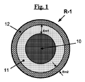
本明細書に添付した図1は、本発明に従う複合補強材の第1の例を、断面において極めて略図的に示している(特定の縮尺で描いていない)。R‐1で示すこの複合補強材は、例えば、炭素鋼製の比較的大直径(例えば、0.10mmと0.50mmの間)を有する単一フィラメントまたはモノフィラメントからなる補強用スレッド(10)からなり、スレッド(10)は、例えば、ポリアミドまたはポリエステルから製造したプラスのガラス転移温度(Tg1)を有する熱可塑性ポリマーの第1層(11)によって被覆されており、この層の最小厚は、図1にEm1で示している。マイナスのガラス転移温度(Tg2)を有する不飽和TPSエラストマー、例えば、SBS、SBBS、SISまたはSBISの第2層(12)は、第1層(11)を被覆しており、図1にEm2で示す最小厚を有する。 FIG. 1 attached hereto shows a first example of a composite reinforcement according to the invention in a very schematic manner in cross-section (not drawn to a specific scale). This composite reinforcement shown by R-1 consists of a reinforcing thread (10) made of a single filament or a monofilament, for example made of carbon steel and having a relatively large diameter (for example between 0.10 mm and 0.50 mm), The thread (10) is covered, for example, by a first layer (11) of a thermoplastic polymer having a positive glass transition temperature (Tg 1 ) made from polyamide or polyester, the minimum thickness of which is shown in FIG. Is indicated by E m1 . An unsaturated TPS elastomer having a negative glass transition temperature (Tg 2 ), for example a second layer (12) of SBS, SBBS, SIS or SBIS, covers the first layer (11) and is shown in FIG. It has a minimum thickness indicated by m2 .
図2は、本発明に従う複合補強材の第2の例を、断面において略図的に示している。R‐2で示すこの複合補強材は、例えば、炭素鋼製の一緒に撚り合せたまたはケーブル被覆した比較的大直径(例えば、0.10mmと0.50mmの間)を有する2本の単一フィラメントまたはモノフィラメント(20a、20b)から実際になる補強用スレッド(20)からなっている。補強用スレッド(20)は、例えば、6,6 ポリアミドまたはポリエステルから製造し、最小厚Em1を有するプラスのガラス転移温度(Tg1)を有する熱可塑性ポリマーの第1層(21)内に被覆されている。マイナスのガラス転移温度(Tg2)を有し、Em2の最小厚を有する不飽和TPSエラストマー、例えば、SBSまたはSISの第2層(22)は、第1層(21)を被覆している。 FIG. 2 schematically shows a second example of a composite reinforcement according to the invention in cross section. This composite reinforcement, indicated by R-2, is, for example, two single filaments with a relatively large diameter (for example between 0.10 mm and 0.50 mm) twisted together or cable-covered made of carbon steel or The monofilament (20a, 20b) is actually composed of a reinforcing thread (20). The reinforcing thread (20) is made, for example, from 6,6 polyamide or polyester and is coated in a first layer (21) of thermoplastic polymer with a positive glass transition temperature (Tg 1 ) having a minimum thickness E m1. Has been. Having a negative glass transition temperature (Tg 2), the minimum thickness unsaturated TPS elastomer having the E m @ 2, for example, SBS or second layer of SIS (22) coats the first layer (21) .
図3は、本発明に従う複合補強材のもう1つの例を、断面において略図的に示している。R‐3で示すこの複合補強材は、各々が、例えば、鋼または炭素製の一緒に撚り合せたまたはケーブル被覆した比較的大直径(例えば、0.10mmと0.50mmの間)を有する2本のモノフィラメント(30a、30b)からなる3本の補強用スレッド(30)からなっている。例えば、上記3本の配列させた補強用スレッド(30)によって形成したアッセンブリは、プラスのガラス転移温度(Tg1)を有する熱可塑性ポリマー、例えば、ポリアミドまたはポリエステルの第1層(31)によって被覆されている。マイナスのガラス転移温度(Tg2)を有する不飽和TPSエラストマー、例えば、SBS、SBBS、SISまたはSBISの第2層(32)は、第1層(31)を被覆している。 FIG. 3 schematically shows in cross-section another example of a composite reinforcement according to the invention. This composite stiffener, designated R-3, has two relatively large diameters (eg between 0.10 mm and 0.50 mm), each stranded or cabled, eg made of steel or carbon It consists of three reinforcing threads (30) made of monofilaments (30a, 30b). For example, the assembly formed by the three aligned reinforcing threads (30) is covered by a first layer (31) of a thermoplastic polymer having a positive glass transition temperature (Tg 1 ), for example polyamide or polyester. Has been. An unsaturated TPS elastomer having a negative glass transition temperature (Tg 2 ), for example a second layer (32) of SBS, SBBS, SIS or SBIS, covers the first layer (31).
図4は、本発明に従う複合補強材のもう1つの例を、断面において略図的に示している。この複合補強材R‐4は、中心線またはコア線(41a)と該中心線の周りにらせん状に一緒に巻付けた同じ直径を有する6本のフィラメント(41b)とを有する1+6本構成のスチールコードからなる補強用スレッド(40)を含む。この補強用スレッドまたはコード(40)は、6,6 ポリアミドの第1層(42)で被覆されており、この第1層自体は、SBSエラストマーの第2層(43)によって被覆されている。 FIG. 4 schematically shows in cross-section another example of a composite reinforcement according to the invention. This composite reinforcement R-4 has a 1 + 6 configuration comprising a center line or core wire (41a) and six filaments (41b) having the same diameter wound together in a spiral around the center line. A reinforcing thread (40) made of steel cord is included. This reinforcing thread or cord (40) is covered by a first layer (6) of 6,6 polyamide, which is itself covered by a second layer (43) of SBS elastomer.
例えば、上記図1〜4において略図的に示している複合補強材のような本発明に従う複合補強材においては、上記2つの層の最小厚(Em1およびEm2)は、本発明の特定の製造条件に応じて、極めて広く変動し得る。
第1層の最小厚Em1は、好ましくは1μmと2mmの間、より好ましくは10μmと1mmの間である。
For example, in a composite reinforcement according to the present invention, such as the composite reinforcement schematically shown in FIGS. 1-4 above, the minimum thickness (E m1 and E m2 ) of the two layers is a specific value of the present invention. Depending on the manufacturing conditions, it can vary quite widely.
The minimum thickness E m1 of the first layer is preferably between 1 μm and 2 mm, more preferably between 10 μm and 1 mm.
本発明の特定の実施態様によれば、第2層の最小厚Em2は、第1層の最小厚と同程度の数値を有し得るか(例えば1μmと2mmの間、特に10μmと1mmの間の厚さを有する厚い第2層の場合)、或いは明確に異なり得る。
もう1つの特定の実施態様によれば、第2層は、例えば、押出によらないでコーティングまたはスプレー法或いは他の薄または超薄付着法によって付着させ、例えば、0.02μmと1μmの間、特に0.05μmと0.5μmの間の厚さを有する薄いまたは超薄接着層によって形成させ得る。
According to a particular embodiment of the invention, the minimum thickness E m2 of the second layer may have a numerical value comparable to the minimum thickness of the first layer (for example between 1 μm and 2 mm, in particular between 10 μm and 1 mm) In the case of a thick second layer having a thickness in between) or may be clearly different.
According to another particular embodiment, the second layer is deposited by, for example, coating or spraying without other extrusion or other thin or ultrathin deposition methods, for example between 0.02 μm and 1 μm, in particular It can be formed by a thin or ultra thin adhesive layer having a thickness between 0.05 μm and 0.5 μm.
複数本の補強用スレッドを使用する場合、第1および第2層は、例えば上記で説明した図1、2および4に示しているように、補強用スレッドの各々上に個々に付着させ得る(注:これらの補強用スレッドは、単一であり得或いはあり得ない)。しかしながら、第1および第2層は、例えば図3に示しているように、適切に整列させた、例えば、主方向に沿って配列させた複数本の補強用スレッド上に集合的に付着させてもよい。 When multiple reinforcing threads are used, the first and second layers can be individually deposited on each of the reinforcing threads, for example as shown in FIGS. 1, 2 and 4 described above ( (Note: these reinforcing threads may or may not be single). However, the first and second layers are collectively deposited on a plurality of reinforcing threads that are appropriately aligned, for example, aligned along the main direction, as shown, for example, in FIG. Also good.
本発明の複合補強材は、少なくとも下記の工程を含む特定の方法によって製造する:
・第1工程において、少なくとも1本の補強用スレッドを、先ず、プラスのガラス転移温度を有する熱可塑性ポリマーの第1層で被覆し;
・次に、第2工程において、マイナスのガラス転移温度を有する不飽和TPSエラストマーの第2層を、そのようにして被覆した上記スレッド(1本以上)上に付着させ;そして、
・最後に、アッセンブリを熱‐酸化処理に供して上記2つの層を一緒に結合させる。
The composite reinforcement of the present invention is produced by a specific method including at least the following steps:
In a first step, at least one reinforcing thread is first coated with a first layer of thermoplastic polymer having a positive glass transition temperature;
-Next, in a second step, a second layer of unsaturated TPS elastomer having a negative glass transition temperature is deposited on the thread (s) so coated; and
• Finally, subject the assembly to a heat-oxidation process to bond the two layers together.
最初の2工程は、当業者にとって既知の方法で、インラインまたは他の方式で連続して実施する。例えば、これらの工程は、単純に、上記補強用スレッドを適切な温度に加熱した押出ヘッド内の適切な直径のダイに通すことからなる。 The first two steps are performed in-line or sequentially in a manner known to those skilled in the art. For example, these steps simply consist of passing the reinforcing thread through a suitably sized die in an extrusion head heated to a suitable temperature.
好ましい実施態様によれば、単数または複数の上記補強用スレッドを、例えば、誘導加熱によってまたはIR照射によって、それぞれの押出ヘッドに通す前に予熱する。各押出ヘッドを出た時点で、そのようにしてシーズした単数または複数の補強用スレッドを、その後、例えば、低温の空気または他のガスを使用して或いはスレッド(1本以上)を水浴に、次いで、乾燥工程に通すことによって、それぞれのポリマー層が固化するのに十分に冷却する。 According to a preferred embodiment, the reinforcing thread or threads are preheated before passing through the respective extrusion head, for example by induction heating or by IR irradiation. Upon exiting each extrusion head, the reinforcing thread or threads so seeded are then used, for example using cold air or other gas or thread (s) in a water bath, The polymer layer is then cooled sufficiently to solidify by passing through a drying step.
次の工程は、熱‐酸化処理からなる。用語“熱‐酸化処理”は、定義によれば、酸素、例えば、空気中の酸素の存在下での加熱処理を意味するものと理解されたい。熱‐酸化処理なしでは、TPS第2層の熱可塑性ポリマー第1層への許容し得る接着を得るのが不可能であることが判明している(例えば、真空加熱処理は、完全に効果がないことが判明している)。 The next step consists of a thermo-oxidation treatment. The term “thermal-oxidation treatment” is to be understood by definition to mean a heat treatment in the presence of oxygen, for example oxygen in the air. It has been found that without heat-oxidation treatment it is impossible to obtain an acceptable adhesion of the TPS second layer to the thermoplastic polymer first layer (eg, vacuum heat treatment is completely effective). Not known).
一例としては、約0.6mmの直径を有する補強用スレッド、例えば、一緒に撚り合せた直径0.3mmの2本の個々のモノフィラメントから単純になる金属コード(例えば、図2に示すような)を、約0.4mmに等しい最大厚を有する6,6 ポリアミド第1層で被覆して、約1mmの総直径を有するシーズした補強用スレッドを、2つのダイを含む押出/シーズ処理ライン上で得る;第1ダイ(カウンターダイまたは上流ダイ)は約0.65mmに等しい直径を有し、第2ダイ(または下流ダイ)は約0.95mmに等しい直径を有し、両ダイは約300℃に加熱した押出ヘッド内に置かれている。上記ポリアミドは、押出機内で290℃の温度で溶融し、そのようにして、シーズ処理ヘッドを通過するときの補強用スレッドを、典型的に数十cm3/分の押出ポンプ速度において典型的には数十m/分のスレッド操作速度で被覆する。この第1のシーズ処理ダイを出た時点で、スレッドを、上記ポリアミドがその非晶質状態に固化し凝固するための、低温水を満たした冷却タンク中に浸漬し、その後、例えば、巻取りリールをオーブン内で加熱することによって乾燥させる。 As an example, a reinforcing thread having a diameter of about 0.6 mm, for example a metal cord that is simply made up of two individual monofilaments with a diameter of 0.3 mm twisted together (eg as shown in FIG. 2) Coated with a 6,6 polyamide first layer having a maximum thickness equal to about 0.4 mm, a sheathed reinforcing thread having a total diameter of about 1 mm is obtained on an extrusion / seeding line containing two dies; One die (counter die or upstream die) has a diameter equal to about 0.65 mm, the second die (or downstream die) has a diameter equal to about 0.95 mm, and both dies are extrusion heads heated to about 300 ° C. Is placed inside. The polyamide melts in the extruder at a temperature of 290 ° C., so that the reinforcing thread as it passes through the seeding head is typically at an extrusion pump speed of typically several tens of cm 3 / min. Is covered with a thread operating speed of several tens of m / min. Upon exiting this first seeding die, the thread is immersed in a cooling tank filled with low temperature water to allow the polyamide to solidify and solidify into its amorphous state and then, for example, wind up The reel is dried by heating in an oven.
その後、ポリアミドでそのようにして被覆したスレッドを、不飽和TPSエラストマーによって、第2層において意図した厚さに適応させた1つの実施態様に従い被覆する。
第1の例としては、第2層の意図する厚さが約0.1mmである場合、6,6 ポリアミドで被覆したスレッドを、シーズ処理ヘッドを200℃の温度に加熱し、直径1.1mmの第1カウンターダイと直径1.2mmの第2ダイを装着した押出‐シーズ処理ラインに逆に通し得る。例えば、押出機内で約180℃の温度に加熱した不飽和TPSエラストマーは、そのようにして、上記スレッドを、典型的には数cm3/分〜数十cm3/分の押出ポンプ産出量において典型的には数m/分〜数十m/分の操作速度で上記シーズ処理ヘッドに通すことによって被覆する。
The thread so coated with polyamide is then coated with an unsaturated TPS elastomer according to one embodiment adapted to the intended thickness in the second layer.
As a first example, if the intended thickness of the second layer is about 0.1 mm, a thread coated with 6,6 polyamide is heated to a temperature of 200 ° C. in a sheathed head and a 1.1 mm diameter It can be passed back through an extrusion-seeding line equipped with one counter die and a second die with a diameter of 1.2 mm. For example, an unsaturated TPS elastomer heated to a temperature of about 180 ° C. in an extruder can thus do the thread, typically at an extrusion pump output of a few cm 3 / min to a few tens cm 3 / min. Typically, the coating is carried out by passing through the seeding head at an operating speed of several m / min to several tens m / min.
第2の例としては、第2層の意図する厚さが極めて実質的に小さく、例えば、数十ナノメートルに等しい場合、6,6 ポリアミドで被覆したスレッドは、例えば、数m/分〜数十m/分の速度で、また、1kgの質量でプレスし且つ適切な溶媒中に希釈したTPSエラストマー(例えば、トルエン中5%に希釈したSBS)を連続して吸収した2枚のウールベーズ(wool baize)要素間を通過し、この方法で、スレッド全体をTPSエラストマー(SBS)の超薄層で被覆する。
上記の2つの連続するシーズ処理工程においては、上記コード(補強用スレッド)を、有利には、押出ヘッドに通す前に、例えば、高周波発生器にまたは加熱用トンネルに通すことによって予熱する。
As a second example, if the intended thickness of the second layer is very substantially small, for example equal to several tens of nanometers, a thread coated with 6,6 polyamide can be, for example, several meters / minute to several Two wool bays (wool) continuously absorbed at a rate of 10 m / min and continuously with a TPS elastomer pressed at a mass of 1 kg and diluted in a suitable solvent (eg SBS diluted to 5% in toluene) In this way, the entire thread is covered with an ultra-thin layer of TPS elastomer (SBS).
In the above two successive seeding steps, the cord (reinforcing thread) is advantageously preheated, for example by passing it through a high frequency generator or through a heating tunnel, before passing it through the extrusion head.
第2の操作後、即ち、上述した加熱ヘッドまたはコーティング浴を出た時点で直接、本発明の特定の実施態様に応じて、複合スレッドは、例えば長さ数メートルのトンネル炉を通り、その中で空気中の加熱処理を受ける。
処理温度は、例えば、場合に応じての数秒〜数分の処理時間において150℃と300℃の間である;処理時間が短いほど温度は高いことおよび上記加熱処理は、必ずしも、使用する熱可塑性材料に再溶融をそれとも過剰の軟化をもたらす必要はないことはないことを理解されたい。
そのようにして完成させた本発明の複合補強材は、有利には、例えば空気中で冷却して、望ましくない粘着問題を回避すると共に、最終の巻取りリール上に巻上げる。
Depending on the particular embodiment of the invention, after the second operation, i.e. directly upon exiting the heating head or coating bath described above, the composite thread passes, for example, through a tunnel furnace of several meters in length, In the air heat treatment.
The treatment temperature is, for example, between 150 ° C. and 300 ° C. for a treatment time of a few seconds to a few minutes depending on the case; the shorter the treatment time, the higher the temperature and the heat treatment is not necessarily the thermoplastic used It should be understood that the material need not be remelted or cause excessive softening.
The composite reinforcement of the present invention thus completed is advantageously cooled, for example in air, to avoid undesirable sticking problems and wind up on the final take-up reel.
当業者であれば、上記処理の温度および時間を、本発明の特定の操作条件に応じて、特に、製造した複合補強材の正確な性質に応じて、特に、上記処理が、個々に使用したモノフィラメント、数本のモノフィラメントまたはそのようなモノフィラメントの1群を含むコード或いはストリップのようなコードのいずれに対するのかに応じて、如何にして調整するは承知していることであろう。
特に、当業者であれば、処理温度および処理時間を変更して、継続的な近似化により、本発明の特定の実施態様毎に最良の接着結果を得る操作条件を見出すという利益を有するであろう。
The person skilled in the art uses the treatment temperature and time individually according to the specific operating conditions of the invention, in particular according to the exact nature of the composite reinforcement produced. It will be appreciated how to adjust depending on whether it is for a monofilament, several monofilaments or a cord such as a cord comprising a group of such monofilaments or a strip.
In particular, those skilled in the art have the benefit of finding the operating conditions to obtain the best adhesion results for each specific embodiment of the present invention by varying the processing temperature and processing time and by continuous approximation. Let's go.
上記で説明した本発明に従う方法の工程には、上記補強材、より正確には、そのTPSエラストマー第2層を三次元架橋させて、特にこの複合補強材を典型的には100℃よりも高い比較的高温において最終的に使用することを意図する場合に、その固有凝集力をさらに増進させる最終処理を追加し得る。 In the process steps according to the invention described above, the reinforcing material, more precisely its TPS elastomer second layer, is three-dimensionally cross-linked, in particular this composite reinforcing material is typically above 100 ° C. When intended for final use at relatively high temperatures, a final treatment can be added that further enhances its intrinsic cohesive strength.
この架橋は、任意の既知の方法によって、例えば、イオンまたは電子衝撃のような物理的架橋方法によって、或いは化学的架橋方法によって、例えば、架橋剤(例えば、アマニ油)を、TPSエラストマーに、例えば、押出加工しながら混入することによってまたは加硫(即ち、イオウベースの)系をTPSエラストマーに混入することによって実施し得る。
また、架橋は、本発明の複合補強材により補強を意図するタイヤ(または、より一般的にはゴム物品)を製造する間にも、そのようなタイヤ(またはゴム物品)を製造するのに使用するジエンゴム組成物中に存在して本発明の複合補強材と接触する固有の架橋系によって生じ得る。
This cross-linking may be performed by any known method, e.g., by physical cross-linking methods such as ion or electron bombardment, or by chemical cross-linking methods, e.g. cross-linking agents (e.g. linseed oil) to TPS elastomers e.g. It can be carried out by mixing during extrusion or by incorporating a vulcanized (ie sulfur-based) system into the TPS elastomer.
Crosslinking is also used to produce such tires (or rubber articles) while producing tires (or more generally rubber articles) that are intended to be reinforced with the composite reinforcement of the present invention. May be caused by an inherent crosslinking system that is present in the diene rubber composition that contacts the composite reinforcement of the present invention.
本発明の複合補強材は、直接、即ち、何らの追加の接着系を必要としないで、例えばタイヤにおけるジエンゴムマトリックス用の補強要素として使用することができる。有利なことに、本発明の複合補強材は、全てのタイプの車両用の、特に、乗用車または重量車のような産業用車両用のタイヤを補強するのに使用し得る。 The composite reinforcement of the present invention can be used directly, i.e. without the need for any additional adhesive system, for example as a reinforcing element for a diene rubber matrix in a tire. Advantageously, the composite reinforcement of the present invention can be used to reinforce tires for all types of vehicles, especially industrial vehicles such as passenger cars or heavy vehicles.
1つの例として、本明細書に添付した図5は、乗用車用の本発明に従うタイヤの半径断面を極めて略図的に示している(特定縮尺に準じて描いていない)。
このタイヤ1は、クラウン補強材即ちベルト6によって補強されたクラウン2、2つの側壁3および2つのビード4を有し、これらのビード4の各々は、ビードワイヤー5によって補強されている。クラウン2は、トレッド(この略図には示していない)が取付けられている。カーカス補強材7は、各ビード4内の2本のビード線5の周りに巻付けられており、この補強材7の上返し8は、例えば、タイヤ1の外側に向って位置しており、この場合、タイヤリム9上に取付けて示している。カーカス補強材7は、それ自体知られている通り、コード、いわゆる“ラジアル”コード、例えば、繊維または金属コードによって補強されている少なくとも1枚のプライからなる、即ち、これらのコードは、実際上、互いに平行に配置されて一方のビードから他方のビードに延びて円周正中面(2つのビード4からの中間距離に位置しクラウン補強材6の中央を通るタイヤの回転軸に対して垂直の面)と80°と90°の間の角度をなしている。
As an example, FIG. 5 attached herewith shows a very schematic radial cross-section of a tire according to the invention for passenger cars (not drawn to specific scale).
The
本発明のこのタイヤ1は、例えば、そのクラウンまたはカーカス補強材の少なくとも1つが本発明に従う複合補強材を含むという本質的な特徴を有する。本発明のもう1つの可能性ある実施態様によれば、その実施態様は、本発明に従う複合補強材から製造し得るビード線5である。
This
本発明の実施態様
試験 1:複合補強材の製造
本発明に従うまたは従わない複合補強材を、先ず、以下の方法で製造した。出発補強用スレッドは、10mmのらせんピッチで一緒に撚り合せた直径0.30mmの2本の個々のスレッドまたはモノフィラメントからなる1×2構造での標準鋼(0.7質量%の炭素含有量を有する)から製造されたタイヤ用のスチールコードであった。コード直径は0.6mmであった。
Embodiment of the present invention
Test 1: Production of Composite Reinforcement A composite reinforcement according to or not following the present invention was first produced by the following method. The starting reinforcement thread is from a standard steel (having a carbon content of 0.7% by weight) in a 1 × 2 structure consisting of two individual threads or monofilaments of diameter 0.30 mm twisted together at a helical pitch of 10 mm It was a steel cord for a manufactured tire. The cord diameter was 0.6 mm.
このコードを、6,6 ポリアミド(DuPont de Nemours社からのZYTEL E40 NC010;約260℃に等しい融点Tm)で被覆した;被覆は、押出‐シーズ処理ラインにおいて、上記コードを300℃の温度に加熱し且つ2つのダイ(直径0.63mmの上流ダイと直径0.92mmの下流ダイ)を含む押出ヘッドに通すことによって実施した。押出機(20cm3/分のポンプ速度)内で約290℃の温度に加熱したポリアミドは、そのようにして、30m/分の速度で通過する上記スレッド(高周波発生器に通すことによって約280〜290℃に予熱した)を被覆した。シーズ処理ヘッドを出た時点で、得られた複合補強材は、5℃の水を満たした冷却用タンクに連続して移動し、ポリアミドが、空気ノズルを使用して乾燥させる前に、その非晶質状態に固化した。 This cord was coated with 6,6 polyamide (ZYTEL E40 NC010 from DuPont de Nemours; melting point T m equal to about 260 ° C.); the coating was placed at a temperature of 300 ° C. in an extrusion-seeds treatment line. This was done by heating and passing through an extrusion head containing two dies (an upstream die with a diameter of 0.63 mm and a downstream die with a diameter of 0.92 mm). Polyamide heated to a temperature of about 290 ° C. in an extruder (20 cm 3 / min pumping speed), so that the above thread passing at a speed of 30 m / min (by passing through a high frequency generator about 280- Preheated to 290 ° C.). Upon exiting the seeding head, the resulting composite reinforcement is continuously transferred to a cooling tank filled with water at 5 ° C, before the polyamide is dried using an air nozzle. Solidified to a crystalline state.
製造のこの段階は、そのポリアミド第1層でのみシーズされた初期スチールコードからなる対照複合補強材(従って、本発明に従わない)をもたらした。この対照複合補強材(R‐5で示す)は、約1.0mmの総直径を有していた(即ち、1回のシーズ処理)。 This stage of manufacture resulted in a control composite reinforcement (thus not in accordance with the invention) consisting of an initial steel cord seeded only with the polyamide first layer. This control composite reinforcement (denoted R-5) had a total diameter of about 1.0 mm (ie, a single seeding process).
次に、第2工程において、SBS熱可塑性エラストマー(Kraton社からのD1118)の第2層(その意図する最小厚(Em2)は約0.1mm)を、そのようにシーズした上記コード上に以下の方法で付着させた。6,6 ポリアミドで被覆したコード(加熱用トンネルに通すことによって約100℃に予熱)を、シーズ処理ヘッドを200℃の温度に加熱し且つ直径1.1mmの上流ダイと直径1.2mmの下流ダイを装着させている第2の押出‐シーズ処理ラインに逆に通した。押出機内で180℃の温度に加熱されたSBSエラストマーは、そのようにして、シーズ処理ヘッドに3m/分の操作速度で通す(ポンプ速度:2cm3/分)ことによって、上記コードを被覆した。 Next, in the second step, a second layer of SBS thermoplastic elastomer (D1118 from Kraton) (its intended minimum thickness (E m2 ) is about 0.1 mm) is placed on the above-seeded cord as follows: It was made to adhere by the method of. 6,6 A cord coated with polyamide (preheated to about 100 ° C by passing through a heating tunnel), heat the seeding head to a temperature of 200 ° C, and connect an upstream die with a diameter of 1.1 mm and a downstream die with a diameter of 1.2 mm Passed back through the second extrusion-seeds processing line installed. The SBS elastomer heated to a temperature of 180 ° C. in the extruder was thus coated with the cord by passing it through a seeding head at an operating speed of 3 m / min (pump speed: 2 cm 3 / min).
上記で使用した2つのポリマーのガラス転移温度(Tg1およびTg2)は、それぞれ、約+50℃および−95℃に等しかった(Mettler Toledo社からの822‐2 DSC装置;ヘリウム雰囲気、室温(20℃)から100℃に予熱し(20℃/分で)、次いで、20℃/分にて−140℃から+250℃までのDSC曲線を最終的に記録する前に、−140℃に急速冷却した試験標本)。 The glass transition temperatures (Tg 1 and Tg 2 ) of the two polymers used above were equal to about + 50 ° C. and −95 ° C., respectively (822-2 DSC apparatus from Mettler Toledo; helium atmosphere, room temperature (20 C.) to 100 ° C. (at 20 ° C./min), then rapidly cooled to −140 ° C. before finally recording a DSC curve from −140 ° C. to + 250 ° C. at 20 ° C./min Test specimen).
この第2のシーズ処理操作後、アッセンブリ(二重シーズ被覆した複合補強材)は、トンネル炉に、270℃の温度に加熱した周囲雰囲気において約100秒間通すことによって熱‐酸化処理を受けた。この製造の最終段階は、そのポリアミド第1層によって、さらに、そのSBSエラストマー第2層によってシーズされた初期スチールコードからなる本発明に従う複合補強材をもたらした。この方法で製造した本発明に従う複合補強材(図2に略図的に示しているような補強材R‐2)は、約1.1mmの最終総直径を有していた。 After this second seeding operation, the assembly (double sheathed composite reinforcement) was subjected to a heat-oxidation treatment by passing it through a tunnel furnace in an ambient atmosphere heated to a temperature of 270 ° C. for about 100 seconds. This final stage of manufacture resulted in a composite reinforcement according to the invention consisting of an initial steel cord seeded by the polyamide first layer and by the SBS elastomer second layer. The composite reinforcement according to the invention produced in this way (reinforcement R-2 as schematically shown in FIG. 2) had a final total diameter of about 1.1 mm.
上記の試験における熱‐酸化処理の最良の操作条件を決定するために、4通りの処理時間(50秒、100秒、200秒および400秒)における160℃から280℃までの温度範囲を、前以って検証していた。 In order to determine the best operating conditions of the thermo-oxidation treatment in the above test, the temperature range from 160 ° C to 280 ° C at the four treatment times (50 seconds, 100 seconds, 200 seconds and 400 seconds) This was verified.
試験 2:接着試験
その後、ゴムと上記で製造した複合補強材との結合の質を、上記補強材を加硫物とも称する加硫ゴム組成物から引き抜くのに要する力を測定する試験によって評価した。このゴム組成物は、天然ゴム、カーボンブラックおよび標準添加剤をベースとする、金属タイヤベルトプライのカレンダー加工において使用する通常の組成物であった。
Test 2: Adhesion test The quality of the bond between the rubber and the composite reinforcement produced above was then evaluated by a test measuring the force required to pull the reinforcement from the vulcanized rubber composition, also referred to as vulcanizate. . This rubber composition was a conventional composition used in calendering of metal tire belt plies based on natural rubber, carbon black and standard additives.
加硫物は、200mm×4.5mmを計測し3.5mmの厚さを有し、硬化前に互いに対して適用した2枚のシーズからなるゴムブロックであった(得られたブロックの厚さは、その場合、7mmであった)。このブロックの引抜きにおいては、複合補強材(総計で15本のストランド)を未硬化状態の2枚のシートの間に等間隔で離れて閉じ込め、各複合補強材の一端がこれらのシートのいずれかの側面上にその後の引張試験のための十分な量突出するようにした。その後、上記補強材を含むブロックを適切なモールド内に入れ、次いで、圧力下に硬化させた。当業者の裁量に委ねる硬化温度および硬化時間を、意図する試験条件に適応させた。例えば、本例においては、ブロックを、16バールの圧力下に160℃で15分間硬化させた。 The vulcanizate was a rubber block consisting of two sheaths applied to each other before curing, measuring 200 mm x 4.5 mm and having a thickness of 3.5 mm (the thickness of the resulting block is In that case, it was 7 mm). In drawing out this block, the composite reinforcement (total of 15 strands) is confined at an equal interval between two uncured sheets, and one end of each composite reinforcement is one of these sheets. A sufficient amount for subsequent tensile testing was allowed to protrude on the side. Thereafter, the block containing the reinforcing material was placed in a suitable mold and then cured under pressure. Curing temperature and curing time at the discretion of the skilled person were adapted to the intended test conditions. For example, in this example, the block was cured for 15 minutes at 160 ° C. under a pressure of 16 bar.
硬化させた後、そのように加硫ブロックと15本の補強材からなる試験標本を適切な引張試験装置の顎の間に置いて各補強材をゴムから所定の引張速度および所定の温度(例えば、本例においては、それぞれ、50mm/分および20℃)で個々に引張った。接着レベルは、補強材を試験標本から引抜くための引抜き力(Fmaxで示す)を測定することによって特性決定した(このレベルは、15回の引張試験の平均である)。 After curing, a test specimen consisting of a vulcanization block and 15 reinforcements is placed between the jaws of a suitable tensile test device so that each reinforcement is removed from the rubber at a predetermined tensile speed and a predetermined temperature (e.g. In this example, they were individually pulled at 50 mm / min and 20 ° C., respectively. The adhesion level was characterized by measuring the pulling force (denoted Fmax ) to pull the reinforcement from the test specimen (this level is an average of 15 tensile tests).
本発明の複合補強材は、RFL接着剤(またはあらゆる他の接着剤)を含有しないという事実にもかかわらず、ナイロンシーズ被覆対照複合補強材(R‐5)について測定し、また、通常のRFL接着剤を使用して結合させた対照引抜き力の約60%に等しい高引抜き力Fmaxを有することを見出した。
同じ試験条件下において、ナイロンでシーズ被覆したがRFL接着剤(またはあらゆる他の接着剤)を含有しない対照複合補強材(R‐5)は、ゴムへの接着を示さなかった(実際にゼロの引抜き力)。
Despite the fact that the composite reinforcement of the present invention does not contain an RFL adhesive (or any other adhesive), it was measured on a nylon seeded coated composite composite reinforcement (R-5), and the normal RFL It has been found that it has a high pull force F max equal to about 60% of the control pull force bonded using the adhesive.
Under the same test conditions, the control composite reinforcement (R-5) sheathed with nylon but containing no RFL adhesive (or any other adhesive) showed no adhesion to rubber (actually zero). Pulling force).
本発明の複合補強材において得られた結果は、特に、熱‐酸化処理前では、同じ複合補強材の引抜き力も実際にゼロに等しいことが判明していることから、当業者にとっては、顕著で且つ予想外の双方である。
また、さらなる試験は、不飽和TPSエラストマー(SBS)の第2シーズ被覆層としてではなくゴムカレンダー加工用組成物中に混入させた接着剤としての使用(従って、複合補強材と常に接触している)は、接着剤寄与をもたらさなかったことを実証していた。
The results obtained with the composite reinforcement of the present invention are notable for those skilled in the art, especially before heat-oxidation treatment, since it has been found that the pull-out force of the same composite reinforcement is actually equal to zero. And both are unexpected.
Further tests have also shown that the use of unsaturated TPS elastomers (SBS) as an adhesive incorporated in rubber calendering compositions rather than as a second sheath coating (and therefore in constant contact with the composite reinforcement) ) Demonstrated that it did not result in an adhesive contribution.
結果として、本発明の複合補強材は、その自己接着特性のために、得られた接着レベルにより、ポリアミドまたはポリエステルのような熱可塑性材料でシーズ被覆し、知られている通り、ゴムに接着するのを確保するためにはRFL接着剤の使用を必要とする従来技術に複合補強材にとっての有用で且つ全く信頼し得る代替品を構成する。 As a result, due to its self-adhesive properties, the composite reinforcement of the present invention is sheathed with a thermoplastic material such as polyamide or polyester and adheres to rubber as is known, depending on the level of adhesion obtained. In order to ensure this, the prior art, which requires the use of RFL adhesives, constitutes a useful and quite reliable alternative for composite reinforcements.
R‐1 本発明に従う複合補強材の第1の例
(10) 補強用スレッド
(11) マイナスのガラス転移温度を有する熱可塑性ポリマーの第1層
(12) プラスのガラス転移温度を有する不飽和TPSエラストマーの第2層
Em1 第1層の最小厚
Em2 第1層の最小厚
R-1 First example of composite reinforcement according to the present invention
(10) Reinforcing thread
(11) First layer of thermoplastic polymer having negative glass transition temperature
(12) Second layer of unsaturated TPS elastomer with positive glass transition temperature
E m1 Minimum thickness of first layer
Minimum thickness of E m2 first layer
R‐2 本発明に従う複合補強材の第2の例
(20) 補強用スレッド
(20a、20b) 単一フィラメントまたはモノフィラメント
(21) マイナスのガラス転移温度を有する熱可塑性ポリマーの第1層
(22) プラスのガラス転移温度を有する不飽和TPSエラストマーの第2層
R-2 Second example of composite reinforcement according to the present invention
(20) Reinforcing thread
(20a, 20b) Single filament or monofilament
(21) First layer of thermoplastic polymer having negative glass transition temperature
(22) Second layer of unsaturated TPS elastomer with positive glass transition temperature
R‐3 本発明に従う複合補強材のもう1つの例
(30) 補強用スレッド
(30a、30b) モノフィラメント
(31) マイナスのガラス転移温度を有する熱可塑性ポリマーの第1層
(32) プラスのガラス転移温度を有する不飽和TPSエラストマーの第2層
R-3 Another example of composite reinforcement according to the present invention
(30) Reinforcing thread
(30a, 30b) Monofilament
(31) First layer of thermoplastic polymer having negative glass transition temperature
(32) Second layer of unsaturated TPS elastomer with positive glass transition temperature
R‐4 本発明に従う複合補強材のもう1つの例
(40) 補強用スレッド
(41a) 中心またはコア線
(41b) 同じ直径を有する6本のフィラメント
(42) 6,6 ポリアミドの第1層
(43) SBSエラストマーの第2層
R-4 Another example of composite reinforcement according to the present invention
(40) Reinforcing thread
(41a) Center or core wire
(41b) 6 filaments with the same diameter
(42) 6,6 First layer of polyamide
(43) Second layer of SBS elastomer
1 タイヤ
2 クラウン
3 側壁
4 ビード
5 ビード線
6 クラウン補強材(ベルト)
7 カーカス補強材
8 カーカス補強材の上返し
9 タイヤリム
1
7
Claims (9)
・少なくとも1本の補強用スレッド;
・前記スレッドを被覆する、ガラス転移温度がプラスである熱可塑性ポリマーの第1層であって、前記熱可塑性ポリマーが、脂肪族ポリアミド、ポリエステル、またはポリイミドである、前記第1層;および、
・前記第1層を被覆する、ガラス転移温度がマイナスである不飽和熱可塑性スチレンエラストマーを含む第2層。 Composite reinforcement characterized by including:
-At least one reinforcing thread;
A first layer of a thermoplastic polymer that covers the thread and has a positive glass transition temperature , wherein the thermoplastic polymer is an aliphatic polyamide, polyester, or polyimide ; and
A second layer comprising an unsaturated thermoplastic styrene elastomer that covers the first layer and has a negative glass transition temperature;
・前記補強用スレッドを、プラスのガラス転移温度を有する前記熱可塑性ポリマーの層で被覆する工程;
・マイナスのガラス転移温度を有する前記不飽和熱可塑性スチレンエラストマーを含む第2層を、そのようにして被覆した前記スレッド上に付着させる工程;および、
・アッセンブリを熱‐酸化処理に供して前記2つの層を一緒に結合させる工程。 The method for producing a composite reinforcing material according to any one of claims 1 to 7 , which can be bonded to a diene rubber matrix, comprising at least the following steps:
Coating the reinforcing thread with a layer of the thermoplastic polymer having a positive glass transition temperature;
Depositing a second layer comprising the unsaturated thermoplastic styrene elastomer having a negative glass transition temperature on the thread so coated; and
• subjecting the assembly to a heat-oxidation treatment to bond the two layers together.
Applications Claiming Priority (3)
| Application Number | Priority Date | Filing Date | Title |
|---|---|---|---|
| FR0951782 | 2009-03-20 | ||
| FR0951782A FR2943269B1 (en) | 2009-03-20 | 2009-03-20 | SELF-ADHERENT COMPOSITE REINFORCEMENT |
| PCT/EP2010/053155 WO2010105975A1 (en) | 2009-03-20 | 2010-03-12 | Self-adhesive composite reinforcement |
Publications (3)
| Publication Number | Publication Date |
|---|---|
| JP2012520945A JP2012520945A (en) | 2012-09-10 |
| JP2012520945A5 JP2012520945A5 (en) | 2013-04-18 |
| JP5694286B2 true JP5694286B2 (en) | 2015-04-01 |
Family
ID=41168689
Family Applications (1)
| Application Number | Title | Priority Date | Filing Date |
|---|---|---|---|
| JP2012500193A Active JP5694286B2 (en) | 2009-03-20 | 2010-03-12 | Self-adhesive composite reinforcement |
Country Status (6)
| Country | Link |
|---|---|
| US (1) | US8973634B2 (en) |
| EP (1) | EP2408612B1 (en) |
| JP (1) | JP5694286B2 (en) |
| CN (1) | CN102361746B (en) |
| FR (1) | FR2943269B1 (en) |
| WO (1) | WO2010105975A1 (en) |
Cited By (1)
| Publication number | Priority date | Publication date | Assignee | Title |
|---|---|---|---|---|
| JP2013542119A (en) * | 2010-09-23 | 2013-11-21 | コンパニー ゼネラール デ エタブリッスマン ミシュラン | Pneumatic tire with self-adhesive composite reinforcement |
Families Citing this family (42)
| Publication number | Priority date | Publication date | Assignee | Title |
|---|---|---|---|---|
| FR2945826B1 (en) * | 2009-05-25 | 2011-12-02 | Michelin Soc Tech | SELF-ADHERENT COMPOSITE REINFORCEMENT |
| FR2948598B1 (en) * | 2009-07-31 | 2011-08-19 | Michelin Soc Tech | COMPOSITE REINFORCEMENT |
| FR2952076B1 (en) * | 2009-10-29 | 2011-12-02 | Michelin Soc Tech | COMPOSITE REINFORCEMENT |
| FR2962454B1 (en) * | 2010-05-20 | 2012-09-21 | Michelin Soc Tech | PROCESS FOR MANUFACTURING A THREE-LAYER METAL CABLE OF THE TYPE IN SITU GUM |
| FR2962456B1 (en) * | 2010-05-20 | 2012-09-21 | Michelin Soc Tech | PROCESS FOR MANUFACTURING A MULTILAYER METALLIC CABLE IN SITU GUM BY AN UNSATURATED THERMOPLASTIC ELASTOMER |
| FR2962455B1 (en) * | 2010-05-20 | 2012-09-21 | Soc Tech Michelin | MULTILAYER METALLIC CABLE GUM IN SITU BY UNSATURATED THERMOPLASTIC ELASTOMER |
| FR2962453B1 (en) * | 2010-05-20 | 2012-09-21 | Michelin Soc Tech | THREE-LAYER METAL CABLE, GUM IN SITU BY UNSATURATED THERMOPLASTIC ELASTOMER |
| FR2963579B1 (en) * | 2010-08-05 | 2013-04-26 | Michelin Soc Tech | COMPOSITE REINFORCEMENT |
| FR2967604B1 (en) * | 2010-11-22 | 2012-12-14 | Michelin Soc Tech | SELF-ADHERENT COMPOSITE REINFORCEMENT |
| FR2971188B1 (en) | 2011-02-03 | 2013-03-08 | Michelin Soc Tech | SOLDER COMPOSITE REINFORCEMENT OF A SELF-ADHERING RUBBER POLYMER LAYER |
| FR2971187B1 (en) * | 2011-02-03 | 2013-03-08 | Michelin Soc Tech | SOLDER COMPOSITE REINFORCEMENT OF A SELF-ADHERING RUBBER POLYMER LAYER |
| FR2982885B1 (en) | 2011-11-23 | 2014-11-07 | Michelin Soc Tech | PROCESS FOR MANUFACTURING A TWO-LAYER IN SITU GEL METAL CABLE WITH AN UNSATURATED THERMOPLASTIC ELASTOMER |
| FR2982884B1 (en) * | 2011-11-23 | 2014-06-06 | Michelin Soc Tech | TWO-LAYER METAL CABLE, GUM IN SITU BY UNSATURATED THERMOPLASTIC ELASTOMER |
| FR2986455B1 (en) | 2012-02-08 | 2014-10-31 | Michelin & Cie | SOLDER COMPOSITE REINFORCEMENT OF A SELF-ADHERING RUBBER POLYMER LAYER |
| FR2986456B1 (en) | 2012-02-08 | 2014-03-07 | Michelin & Cie | SOLDER COMPOSITE REINFORCEMENT OF A SELF-ADHERING RUBBER POLYMER LAYER |
| FR3008998B1 (en) | 2013-07-29 | 2016-01-01 | Michelin & Cie | LOW THICKNESS AND PNEUMATIC REINFORCED PRODUCT COMPRISING THIS PRODUCT |
| FR3008996B1 (en) | 2013-07-29 | 2016-01-01 | Michelin & Cie | LOW THICKNESS AND PNEUMATIC REINFORCED PRODUCT COMPRISING THIS PRODUCT |
| FR3008997B1 (en) | 2013-07-29 | 2016-01-01 | Michelin & Cie | LOW THICKNESS AND PNEUMATIC REINFORCED PRODUCT COMPRISING THIS PRODUCT |
| FR3015363B1 (en) * | 2013-12-19 | 2016-02-05 | Michelin & Cie | MULTI-COMPOSITE REINFORCEMENT |
| FR3020369B1 (en) | 2014-04-29 | 2016-05-06 | Michelin & Cie | MULTI-COMPOSITE FLAT REINFORCEMENT |
| FR3027026B1 (en) | 2014-10-13 | 2016-12-09 | Michelin & Cie | REINFORCED PRODUCT COMPRISING A COMPOSITION COMPRISING A RAPID AND PNEUMATIC VULCANIZATION ACCELERATOR COMPRISING SAID REINFORCED PRODUCT |
| FR3027028B1 (en) | 2014-10-13 | 2016-12-09 | Michelin & Cie | REINFORCED PRODUCT COMPRISING A LOW SULFUR AND PNEUMATIC COMPOSITION COMPRISING SAID REINFORCED PRODUCT |
| FR3027027B1 (en) | 2014-10-13 | 2016-12-09 | Michelin & Cie | REINFORCED PRODUCT COMPRISING A COMPOSITION COMPRISING A METAL OXIDE SYSTEM AND A BALANCED AND PNEUMATIC STEARIC ACID DERIVATIVE COMPRISING SAID REINFORCED PRODUCT |
| FR3027025B1 (en) | 2014-10-13 | 2016-12-09 | Michelin & Cie | REINFORCED PRODUCT COMPRISING A LOW SULFUR AND PNEUMATIC COMPOSITION COMPRISING SAID REINFORCED PRODUCT |
| JP6266498B2 (en) * | 2014-11-26 | 2018-01-24 | 株式会社ブリヂストン | tire |
| FR3032149B1 (en) | 2015-02-03 | 2017-02-17 | Michelin & Cie | RADIAL TIRE HAVING A VERY FINE BELT STRUCTURE |
| FR3032147B1 (en) * | 2015-02-03 | 2017-02-17 | Michelin & Cie | RADIAL TIRE HAVING IMPROVED BELT STRUCTURE |
| FR3036651B1 (en) | 2015-05-28 | 2017-05-19 | Michelin & Cie | MULTI-COMPOSITE FLAT REINFORCEMENT |
| WO2016189209A1 (en) | 2015-05-28 | 2016-12-01 | Compagnie Generale Des Etablissements Michelin | Multi-composite reinforcement made from improved glass-resin |
| FR3041282B1 (en) | 2015-09-21 | 2017-10-20 | Michelin & Cie | METHOD FOR MANUFACTURING A SHEERED REINFORCING ELEMENT COMPRISING A DEGREASING STEP |
| FR3049283B1 (en) * | 2016-03-24 | 2018-03-23 | Compagnie Generale Des Etablissements Michelin | REINFORCED PRODUCT COMPRISING A SELF-ADHESIVE COMPOSITE REINFORCEMENT COMPRISING A BLOCK COPOLYMER |
| FR3051473A1 (en) * | 2016-05-20 | 2017-11-24 | Michelin & Cie | COMPOSITE AND POWER TRANSMISSION BELT |
| JP6785193B2 (en) * | 2017-06-16 | 2020-11-18 | 株式会社ブリヂストン | Resin metal composite members for tires and tires |
| EP3724114B1 (en) | 2017-12-14 | 2023-11-15 | Compagnie Generale Des Etablissements Michelin | Wire guide for producing sheathed reinforcement elements for tyres |
| JP7237074B2 (en) | 2017-12-15 | 2023-03-10 | コンパニー ゼネラール デ エタブリッスマン ミシュラン | Method for producing a product reinforced by reinforcing elements |
| WO2019122686A1 (en) | 2017-12-19 | 2019-06-27 | Compagnie Generale Des Etablissements Michelin | Reinforced product comprising a composition comprising a polysulfide compound and tyre comprising said reinforced product |
| JP2020055494A (en) * | 2018-10-04 | 2020-04-09 | 株式会社ブリヂストン | tire |
| FR3087197B1 (en) | 2018-10-11 | 2020-10-23 | Michelin & Cie | RUBBER COMPONENT INCLUDING REINFORCING ELEMENTS |
| WO2020128261A1 (en) | 2018-12-21 | 2020-06-25 | Compagnie Generale Des Etablissements Michelin | Reinforced product comprising a composition containing a polysulphide compound |
| FR3090644A3 (en) | 2018-12-21 | 2020-06-26 | Michelin & Cie | REINFORCED PRODUCT COMPRISING A COMPOSITION COMPRISING A POLYSULFURATED COMPOUND |
| FR3091206A3 (en) | 2018-12-30 | 2020-07-03 | Michelin & Cie | Wire guide block for the production of sheathed reinforcing elements for tires |
| FR3112783B1 (en) | 2020-07-24 | 2023-04-28 | Michelin & Cie | Reinforced product obtained by a process comprising a step of heat treatment of the sheath |
Family Cites Families (18)
| Publication number | Priority date | Publication date | Assignee | Title |
|---|---|---|---|---|
| FR2271036A1 (en) * | 1973-10-30 | 1975-12-12 | Rhone Poulenc Sa | Rubber reinforced by steel wire - coated with vinyl polymer and compsn. of poly phenol-formaldehyde resin and butadiene-styrene-vinyl pyridine terpolymer |
| FR2576247B1 (en) * | 1985-01-18 | 1987-07-31 | Michelin & Cie | REINFORCING ASSEMBLIES COMPRISING REINFORCEMENT THREADS AND A MATRIX; PROCESS FOR OBTAINING SUCH ASSEMBLIES; ARTICLES COMPRISING SUCH PACKAGES |
| FR2601293B1 (en) | 1986-07-09 | 1988-11-18 | Michelin & Cie | SHEATHED PIPE FOR TIRE COVERS; PROCESS FOR MAKING THIS TRINGLE; TIRE ENCLOSURES COMPRISING THIS TRINGLE. |
| JP2979247B2 (en) * | 1990-12-07 | 1999-11-15 | 横浜ゴム株式会社 | Pneumatic tire |
| FR2736006A1 (en) * | 1995-06-29 | 1997-01-03 | Sedepro | TIRE COMPRISING CIRCUMFERENTIAL CABLES FOR ANCHORING THE CARCASS, PROCESS FOR PREPARING SUCH CABLES |
| JPH1053981A (en) * | 1996-08-06 | 1998-02-24 | Sumitomo Rubber Ind Ltd | Steel cord for tire and pneumatic tire using the same |
| FR2779450B1 (en) | 1998-06-05 | 2001-02-09 | Ciapem Sa Cie Ind D App Menage | LAUNDRY WASHING AND / OR DRYING MACHINE PROVIDED WITH A LAUNDRY WEIGHING DEVICE |
| US6346325B1 (en) * | 1999-07-01 | 2002-02-12 | The Dow Chemical Company | Fiber-reinforced composite encased in a thermoplastic and method of making same |
| DE10023544C1 (en) * | 2000-05-15 | 2002-01-24 | Contitech Antriebssysteme Gmbh | Process for the production of products from polymeric materials, in which reinforcements are embedded |
| AU2001289742A1 (en) * | 2000-07-31 | 2002-02-13 | Michelin Recherche Et Technique S.A. | (metal/rubber) composite for tyre |
| JP4465916B2 (en) * | 2001-05-09 | 2010-05-26 | 横浜ゴム株式会社 | Pneumatic tire using thermoplastic elastomer-coated steel cord |
| AU2003208965A1 (en) * | 2002-02-04 | 2003-09-02 | Bridgestone Corporation | Belt for a pneumatic tire belt made of differente rubber compositions |
| JP4433744B2 (en) * | 2003-09-26 | 2010-03-17 | 横浜ゴム株式会社 | Laminated body and pneumatic tire using the same |
| JP2005262672A (en) * | 2004-03-18 | 2005-09-29 | Sumitomo Rubber Ind Ltd | Method for producing steel cord ply, steel cord ply, and pneumatic tire using it |
| FR2869618B1 (en) | 2004-04-30 | 2008-10-10 | Michelin Soc Tech | IMPROVED ADHESIVE RUBBER COMPOSITION WITH A METAL REINFORCEMENT. |
| FR2910382B1 (en) * | 2006-12-22 | 2009-03-06 | Michelin Soc Tech | PNEUMATIC WITH SELF-SWITCHING LAYER |
| JP4442700B2 (en) * | 2008-05-19 | 2010-03-31 | 横浜ゴム株式会社 | Pneumatic tire and manufacturing method thereof |
| JP2010053495A (en) * | 2008-08-29 | 2010-03-11 | Yokohama Rubber Co Ltd:The | Steel cord for reinforcing tire, and pneumatic tire using the same |
-
2009
- 2009-03-20 FR FR0951782A patent/FR2943269B1/en not_active Expired - Fee Related
-
2010
- 2010-03-12 JP JP2012500193A patent/JP5694286B2/en active Active
- 2010-03-12 EP EP10707922.0A patent/EP2408612B1/en active Active
- 2010-03-12 CN CN201080012989.8A patent/CN102361746B/en active Active
- 2010-03-12 WO PCT/EP2010/053155 patent/WO2010105975A1/en active Application Filing
- 2010-03-12 US US13/257,824 patent/US8973634B2/en not_active Expired - Fee Related
Cited By (1)
| Publication number | Priority date | Publication date | Assignee | Title |
|---|---|---|---|---|
| JP2013542119A (en) * | 2010-09-23 | 2013-11-21 | コンパニー ゼネラール デ エタブリッスマン ミシュラン | Pneumatic tire with self-adhesive composite reinforcement |
Also Published As
| Publication number | Publication date |
|---|---|
| CN102361746B (en) | 2014-10-29 |
| JP2012520945A (en) | 2012-09-10 |
| US20120125506A1 (en) | 2012-05-24 |
| US8973634B2 (en) | 2015-03-10 |
| FR2943269A1 (en) | 2010-09-24 |
| WO2010105975A1 (en) | 2010-09-23 |
| EP2408612B1 (en) | 2013-05-15 |
| EP2408612A1 (en) | 2012-01-25 |
| FR2943269B1 (en) | 2011-04-22 |
| CN102361746A (en) | 2012-02-22 |
Similar Documents
| Publication | Publication Date | Title |
|---|---|---|
| JP5694286B2 (en) | Self-adhesive composite reinforcement | |
| JP5705835B2 (en) | Self-adhesive composite reinforcement and associated manufacturing method, particularly for tires | |
| JP6035570B2 (en) | Pneumatic tire with self-adhesive composite reinforcement | |
| JP5705850B2 (en) | Self-adhesive composite reinforcement | |
| JP5654029B2 (en) | Self-adhesive composite reinforcement | |
| JP5995248B2 (en) | Self-adhesive composite reinforcement | |
| JP5807679B2 (en) | Composite reinforcement | |
| US9821606B2 (en) | Composite reinforcer sheathed with a layer of polymer that is self-adhesive to rubber | |
| JP6082888B2 (en) | Composite reinforcement seeded with rubber self-adhesive polymer layer | |
| JP5782514B2 (en) | Composite reinforcement | |
| JP5995249B2 (en) | Composite reinforcement coated with a self-adhesive polymer layer adhering to rubber | |
| JP6194543B2 (en) | Composite reinforcement seeded with rubber self-adhesive polymer layer | |
| JP5999451B2 (en) | Rubber composite reinforced with textile material with thermoplastic adhesive | |
| BR112013018596B1 (en) | COMPOSITE REINFORCEMENT STACKED WITH A SELF-ADHESIVE POLYMER LAYER TO RUBBER |
Legal Events
| Date | Code | Title | Description |
|---|---|---|---|
| A711 | Notification of change in applicant |
Free format text: JAPANESE INTERMEDIATE CODE: A712 Effective date: 20120810 |
|
| A521 | Request for written amendment filed |
Free format text: JAPANESE INTERMEDIATE CODE: A523 Effective date: 20130227 |
|
| A621 | Written request for application examination |
Free format text: JAPANESE INTERMEDIATE CODE: A621 Effective date: 20130227 |
|
| A977 | Report on retrieval |
Free format text: JAPANESE INTERMEDIATE CODE: A971007 Effective date: 20140411 |
|
| A131 | Notification of reasons for refusal |
Free format text: JAPANESE INTERMEDIATE CODE: A131 Effective date: 20140428 |
|
| A521 | Request for written amendment filed |
Free format text: JAPANESE INTERMEDIATE CODE: A523 Effective date: 20140626 |
|
| TRDD | Decision of grant or rejection written | ||
| A01 | Written decision to grant a patent or to grant a registration (utility model) |
Free format text: JAPANESE INTERMEDIATE CODE: A01 Effective date: 20150105 |
|
| A61 | First payment of annual fees (during grant procedure) |
Free format text: JAPANESE INTERMEDIATE CODE: A61 Effective date: 20150204 |
|
| R150 | Certificate of patent or registration of utility model |
Ref document number: 5694286 Country of ref document: JP Free format text: JAPANESE INTERMEDIATE CODE: R150 |
|
| R250 | Receipt of annual fees |
Free format text: JAPANESE INTERMEDIATE CODE: R250 |
|
| R250 | Receipt of annual fees |
Free format text: JAPANESE INTERMEDIATE CODE: R250 |
|
| R250 | Receipt of annual fees |
Free format text: JAPANESE INTERMEDIATE CODE: R250 |
|
| R250 | Receipt of annual fees |
Free format text: JAPANESE INTERMEDIATE CODE: R250 |
|
| R250 | Receipt of annual fees |
Free format text: JAPANESE INTERMEDIATE CODE: R250 |
|
| R250 | Receipt of annual fees |
Free format text: JAPANESE INTERMEDIATE CODE: R250 |
|
| S531 | Written request for registration of change of domicile |
Free format text: JAPANESE INTERMEDIATE CODE: R313531 |
|
| S111 | Request for change of ownership or part of ownership |
Free format text: JAPANESE INTERMEDIATE CODE: R313113 |
|
| R360 | Written notification for declining of transfer of rights |
Free format text: JAPANESE INTERMEDIATE CODE: R360 |