JP5693678B2 - Developer storage container, developer storage unit, process cartridge, image forming apparatus - Google Patents
Developer storage container, developer storage unit, process cartridge, image forming apparatus Download PDFInfo
- Publication number
- JP5693678B2 JP5693678B2 JP2013160961A JP2013160961A JP5693678B2 JP 5693678 B2 JP5693678 B2 JP 5693678B2 JP 2013160961 A JP2013160961 A JP 2013160961A JP 2013160961 A JP2013160961 A JP 2013160961A JP 5693678 B2 JP5693678 B2 JP 5693678B2
- Authority
- JP
- Japan
- Prior art keywords
- developer
- developer storage
- opening
- layer
- storage container
- Prior art date
- Legal status (The legal status is an assumption and is not a legal conclusion. Google has not performed a legal analysis and makes no representation as to the accuracy of the status listed.)
- Active
Links
Images


Classifications
-
- G—PHYSICS
- G03—PHOTOGRAPHY; CINEMATOGRAPHY; ANALOGOUS TECHNIQUES USING WAVES OTHER THAN OPTICAL WAVES; ELECTROGRAPHY; HOLOGRAPHY
- G03G—ELECTROGRAPHY; ELECTROPHOTOGRAPHY; MAGNETOGRAPHY
- G03G15/00—Apparatus for electrographic processes using a charge pattern
- G03G15/06—Apparatus for electrographic processes using a charge pattern for developing
- G03G15/08—Apparatus for electrographic processes using a charge pattern for developing using a solid developer, e.g. powder developer
- G03G15/0822—Arrangements for preparing, mixing, supplying or dispensing developer
- G03G15/0877—Arrangements for metering and dispensing developer from a developer cartridge into the development unit
- G03G15/0881—Sealing of developer cartridges
- G03G15/0882—Sealing of developer cartridges by a peelable sealing film
-
- G—PHYSICS
- G03—PHOTOGRAPHY; CINEMATOGRAPHY; ANALOGOUS TECHNIQUES USING WAVES OTHER THAN OPTICAL WAVES; ELECTROGRAPHY; HOLOGRAPHY
- G03G—ELECTROGRAPHY; ELECTROPHOTOGRAPHY; MAGNETOGRAPHY
- G03G15/00—Apparatus for electrographic processes using a charge pattern
- G03G15/06—Apparatus for electrographic processes using a charge pattern for developing
- G03G15/08—Apparatus for electrographic processes using a charge pattern for developing using a solid developer, e.g. powder developer
- G03G15/0822—Arrangements for preparing, mixing, supplying or dispensing developer
- G03G15/0877—Arrangements for metering and dispensing developer from a developer cartridge into the development unit
- G03G15/0881—Sealing of developer cartridges
- G03G15/0884—Sealing of developer cartridges by a sealing film to be ruptured or cut
-
- G—PHYSICS
- G03—PHOTOGRAPHY; CINEMATOGRAPHY; ANALOGOUS TECHNIQUES USING WAVES OTHER THAN OPTICAL WAVES; ELECTROGRAPHY; HOLOGRAPHY
- G03G—ELECTROGRAPHY; ELECTROPHOTOGRAPHY; MAGNETOGRAPHY
- G03G15/00—Apparatus for electrographic processes using a charge pattern
- G03G15/06—Apparatus for electrographic processes using a charge pattern for developing
- G03G15/08—Apparatus for electrographic processes using a charge pattern for developing using a solid developer, e.g. powder developer
- G03G15/0822—Arrangements for preparing, mixing, supplying or dispensing developer
- G03G15/0865—Arrangements for supplying new developer
- G03G15/0874—Arrangements for supplying new developer non-rigid containers, e.g. foldable cartridges, bags
Landscapes
- Physics & Mathematics (AREA)
- General Physics & Mathematics (AREA)
- Dry Development In Electrophotography (AREA)
Description
本発明は、現像剤を収納する現像剤収納容器、これを有する現像剤収納ユニット、これを有するプロセスカートリッジ、及び、これらを備える画像形成装置に関する。 The present invention relates to a developer storage container for storing a developer, a developer storage unit having the developer storage unit, a process cartridge having the developer storage unit, and an image forming apparatus including the same.
ここで画像形成装置とは、たとえば電子写真画像形成プロセスを用いて記録媒体に画像を形成するもので、例えば電子写真複写機、電子写真プリンタ(例えば、LEDプリンタ、レーザービームプリンタ等)、電子写真ファクシミリ装置等が含まれる。 Here, the image forming apparatus forms an image on a recording medium using, for example, an electrophotographic image forming process. For example, an electrophotographic copying machine, an electrophotographic printer (for example, an LED printer, a laser beam printer, etc.), electrophotographic A facsimile machine is included.
またプロセスカートリッジとは、現像剤を収納した現像剤収納容器または現像剤収納ユニットと少なくとも感光体を一体的に構成して画像形成装置本体に着脱可能にしたものを言う。 The process cartridge refers to a developer storage container or developer storage unit that stores a developer, and at least a photosensitive member that is integrated with the image forming apparatus main body.
また現像剤収納容器および現像剤収納ユニットは、画像形成装置またはプロセスカートリッジに収納されるものである。 The developer storage container and the developer storage unit are stored in the image forming apparatus or the process cartridge.
従来の電子写真形成プロセスを用いた電子写真画像形成装置には、電子写真感光体及びそれに作用するプロセス手段を一体的にカートリッジ化して、このカートリッジを電子写真画像形成装置本体に着脱可能とするプロセスカートリッジ方式が採用されている。 In a conventional electrophotographic image forming apparatus using an electrophotographic image forming process, an electrophotographic photosensitive member and process means acting on the electrophotographic photosensitive member are integrally formed into a cartridge, and the cartridge can be attached to and detached from the main body of the electrophotographic image forming apparatus. A cartridge system is adopted.
このようなプロセスカートリッジでは、現像剤(トナー、キャリア等)を収納する現像剤収納枠体に設けた開口部をシート状の封止部材で封止している。そして、使用時に封止部材の接合部を引き剥がすことで開口部が開封され現像剤の供給が可能となる方式が広く採用されている(特許文献1参照)。ここで、封止部材を引き剥がす時の負荷を低減するために、封止部材の自由端を折り返し、折り返し部とは逆方向に封止部材を引くことが可能な構成が広く用いられている。 In such a process cartridge, the opening provided in the developer storage frame that stores the developer (toner, carrier, etc.) is sealed with a sheet-like sealing member. And the system which opens an opening part by peeling off the junction part of a sealing member at the time of use, and can supply a developing agent is employ | adopted widely (refer patent document 1). Here, in order to reduce the load when the sealing member is peeled off, a configuration in which the free end of the sealing member can be folded and the sealing member can be pulled in a direction opposite to the folded portion is widely used. .
また、シート状の封止部材を引く力を軽減するために接合パターンを工夫し、開封操作性を向上させたものが特許文献2に開示されている。これは封止部材の引き出し方向の先端部と後端部を山形形状にし、且つ、先端部と後端部の幅を中間部の幅よりも狭くすることで、開口幅が広い封止部材を引いて開封する時の強度を軽減するというものである。 Japanese Patent Application Laid-Open No. H10-228667 discloses a bonding pattern that has been devised to reduce the force of pulling a sheet-like sealing member and the opening operability is improved. This is because the front end and the rear end in the pull-out direction of the sealing member are formed in a mountain shape, and the width of the front end and the rear end is made narrower than the width of the intermediate portion, so that the sealing member having a wide opening width is obtained. The strength when pulling and opening is reduced.
しかしながら、上記従来例では下記の課題があった。 However, the above conventional example has the following problems.
特許文献1には、現像剤の供給の操作性向上や機内飛散防止を目的として、容器の開口部を閉じて現像剤を収納する方法が記載されている。しかしながら、特許文献1では、封止部材を引き剥がす際の開封操作性を向上させる構成については記載されていない。
また、特許文献2では封止部材の形状を引く方向に対し山形形状にすることである程度剥離力を低減し、開封操作性の向上を図っている。しかしながら、更に剥離力を低減するためには、山形形状の頂角を90度よりも小さい鋭角にする必要があり、山形形状も大きくなる。それに伴いシート状の封止部材をシールするためのスペースが必要となるため現像剤収納ユニットが大型化してしまう。
Moreover, in
そこで本発明は、上記従来の技術を更に発展させたものであり、その目的は、封止部材による封止性と封止部材の開封性の両立を安定して向上させることである。 Therefore, the present invention is a further development of the above-described conventional technique, and an object of the present invention is to stably improve both the sealing performance by the sealing member and the unsealing performance of the sealing member.
上記目的を達成するため、本発明は、現像剤を排出するための開口を有しかつ現像剤を収納する現像剤収納容器であって、前記開口を封止し、開封方向に剥離されることによって前記開口を露出することが可能なシール部材を有し、前記シール部材は、前記現像剤収納容器を構成する材料に対して相溶性を有する材料を含む層と、前記層の中に分散し前記現像剤収納容器を構成する材料に対して非相溶性を有する材料を含む複数の分散部と、前記現像剤収納容器の長手方向に伸びる前記現像剤収納容器と接合する接合部と、を有し、前記分散部は、前記開封方向に延伸している形状を有し、前記長手方向と前記開封方向が交差することを特徴とする。 In order to achieve the above object, the present invention provides a developer storage container having an opening for discharging developer and storing the developer, wherein the opening is sealed and peeled in the opening direction. A seal member capable of exposing the opening, and the seal member is dispersed in the layer including a layer containing a material compatible with a material constituting the developer container. A plurality of dispersion portions including a material that is incompatible with the material constituting the developer storage container; and a joint portion that joins the developer storage container extending in a longitudinal direction of the developer storage container. And the said dispersion | distribution part has the shape extended | stretched in the said opening direction, The said longitudinal direction and the said opening direction cross | intersect, It is characterized by the above-mentioned .
本発明によれば、シール部材の材料構成により密封性と開封性の両立を省スペース、且つ、安定して向上することができる。 According to the present invention, space to balance opening property and sealing property of a material constituting the sealing member, and it can be stably improved.
以下、図面を参照して、本発明の好適な実施の形態を例示的に詳しく説明する。ただし、以下の実施形態に記載されている構成部品の寸法、材質、形状、それらの相対配置などは、本発明が適用される装置の構成や各種条件により適宜変更されるべきものである。従って、特に特定的な記載がない限りは、本発明の範囲をそれらのみに限定する趣旨のものではない。 Hereinafter, exemplary embodiments of the present invention will be described in detail with reference to the drawings. However, the dimensions, materials, shapes, and relative arrangements of the components described in the following embodiments should be appropriately changed according to the configuration of the apparatus to which the present invention is applied and various conditions. Therefore, unless specifically stated otherwise, the scope of the present invention is not intended to be limited thereto.
なお、以下の説明で、現像剤収納容器は、少なくとも現像剤を収納する容器と前記容器に設けられた現像剤を排出するための開口部を封止する封止部材を備えるものを指す。 In the following description, the developer storage container refers to a container that includes at least a container that stores the developer and a sealing member that seals an opening for discharging the developer provided in the container.
現像剤を収納する前の現像剤収納容器を、現像剤を収納する為の現像剤収納容器37とする。 The developer storage container before storing the developer is referred to as a developer storage container 37 for storing the developer.
〔実施例1〕
図1は現像剤収納ユニットを有するプロセスカートリッジの主断面図、図2は画像形成装置の主断面図である。
[Example 1]
FIG. 1 is a main cross-sectional view of a process cartridge having a developer storage unit, and FIG. 2 is a main cross-sectional view of an image forming apparatus.
<プロセスカートリッジの構成概要>
プロセスカートリッジは、像担持体と、像担持体に作用するプロセス手段を備えたものである。ここでプロセス手段としては、例えば像担持体の表面を帯電させる帯電手段、像担持体に像を形成する現像装置、像担持体表面に残留した現像剤(トナー、キャリア等を含む)を除去するためのクリーニング手段がある。
<Outline of process cartridge configuration>
The process cartridge includes an image carrier and process means acting on the image carrier. Here, as the process means, for example, a charging means for charging the surface of the image carrier, a developing device for forming an image on the image carrier, and a developer (including toner, carrier, etc.) remaining on the surface of the image carrier are removed. There are cleaning means for.
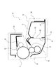
本実施例のプロセスカートリッジAは、図1に示すように像担持体である電子写真感光体ドラム11の周囲に帯電手段である帯電ローラ12、そしてクリーニング手段として弾性を有するクリーニングブレード14を有するクリーナーユニット24を備えている。また、プロセスカートリッジAは、第一の枠体17と、第二の枠体18を有する現像装置38を備えている。プロセスカートリッジAは、クリーナーユニット24と現像装置38とを一体とし、図2に示すように電子写真画像形成装置の装置本体Bに対して着脱自在に構成されている。現像装置38は、現像手段である現像ローラ13と現像ブレード15、現像剤供給ローラ23、を備える。現像ローラ13と、現像ブレード15は、第一の枠体17に支持されている。
As shown in FIG. 1, the process cartridge A of this embodiment is a cleaner having a
<画像形成装置の構成概要>
図2に示すように電子写真画像形成装置の装置本体Bには、前述したプロセスカートリッジが着脱可能に装着されて画像形成に用いられる。装置本体Bの下部に装着されたシートカセット6には、シートSが収納されている。画像形成時には、シートカセット6に収納されたシートSが、搬送ローラ7によって画像形成部に向けて搬送される。このシートSの搬送と同期して、画像形成部を構成する感光体ドラム11に露光装置8から選択的な露光をして潜像を形成する。現像剤は、スポンジ状の現像剤供給ローラ23によって現像ローラ13(現像剤担持体)に供給され、現像ブレード15により現像ローラ13表面に薄層担持される。現像ローラ13に現像バイアスを印加する事によって、潜像に応じて現像剤を供給し、感光体ドラム11に現像剤像を現像する。この像を転写ローラ9へのバイアス電圧印加によって、搬送されるシートSに転写する。現像剤像が転写されたシートSは、定着装置10へ搬送され画像定着され、排出ローラ1によって装置上部の排出部3に排出される。
<Outline of configuration of image forming apparatus>
As shown in FIG. 2, the above-described process cartridge is detachably mounted on the apparatus main body B of the electrophotographic image forming apparatus and used for image formation. Sheets S are stored in a sheet cassette 6 mounted on the lower part of the apparatus main body B. At the time of image formation, the sheet S stored in the sheet cassette 6 is conveyed toward the image forming unit by the conveyance roller 7. In synchronization with the conveyance of the sheet S, the
<現像剤収納ユニットの構成概要>
次に現像剤収納ユニット25の構成について図1を用いて述べる。
<Configuration outline of developer storage unit>
Next, the configuration of the
(現像剤収納ユニット)
現像剤収納ユニット25は図1に示すように現像ローラ13、現像ブレード15と、これらを支持する第一の枠体17と第二の枠体18から構成される。第一の枠体17と第二の枠体18を合わせたものが現像剤を収納する枠体である。
(Developer storage unit)
As shown in FIG. 1, the
なお本実施例では現像剤収納ユニット25は現像装置38と同じである。これは現像剤収納ユニット25が現像ローラ13、現像ブレード15を有しているからである。しかし現像剤収納ユニット25と別枠体で現像ローラ13と現像ブレード15を支持し、現像剤収納ユニット25と分離してもよい。この場合、現像装置38は現像剤収納ユニット25と現像ローラ13、現像ブレード15で構成されたものとなる(不図示)。
In this embodiment, the
<封止部材の構成>
図1に示すように、封止部材19は、プロセスカートリッジAの使用前に、現像剤を排出するための複数の開口部を有する排出部35を覆い、現像剤が排出部35から漏れないように封止している。封止部材19は、移動されることによって前記排出部35を露出させるものである。封止部材19の構成は、排出部35を覆う接合部22を有しているシート状のものである。封止部材19は、排出部35の周囲を接合部22で連続して取り囲み開封可能に接合し現像剤収納容器30に収納する現像剤を封止している。このシート状の封止部材19は、後で説明する易開封性を発揮するシーラント層を持ち、更に補強層を持つラミネート材である。補強層はポリエチレンテレフタレート(PET)、ポリエチレン、ポリプロピレン等で、厚さは0.03〜0.15mmのものを適宜選定すれば良い。
<Configuration of sealing member>
As shown in FIG. 1, the sealing
(封止部材の易開封性を有する部分)
次に、封止部材19の接合部22の剥離力を所望の値にする方法について説明をする。ここでは前記剥離力を所望の値(ここでは、トナー封止性を保てる範囲内でできるだけ小さい力)にするために、次の方法をとっている。
(Part having the easy-opening property of the sealing member)
Next, a method for setting the peeling force of the
図3に示すように、封止部材19は、易開封を可能とするシーラント層39と補強層40を持つラミネート材を適用している。封止部材19の少なくとも一部であるシーラント層39は、現像剤を収納する容器30の素材(材料)に対して相溶性を有する材料51と非相溶性を有する材料52からなる。この相溶性材料51と非相溶性材料52からなるシーラント層39は、相溶性材料51と非相溶性材料52の何れか一方が他方の中で散在した状態で配されている。
As shown in FIG. 3, the sealing
ここで、相溶性を有する材料としては、同材質同士の組み合わせがある。しかし、同材質同士でなくても、相溶性を有する材料の組み合わせがあるため、以下に例示する。 Here, as materials having compatibility, there are combinations of the same materials. However, even if it is not the same material, since there is a combination of compatible materials, it will be exemplified below.
枠体材料であり、非結晶性樹脂であるPS(HIPS含む)に、相溶性を有する材料として、同じく非結晶性樹脂であるABSやPPO等が挙げられる。逆に、非相溶性を有する材料として、結晶性樹脂であるPE、PP、PA、PET、POM等が挙げられる。 Examples of materials that are compatible with PS (including HIPS), which is a frame material and is an amorphous resin, include ABS and PPO, which are also amorphous resins. On the other hand, examples of incompatible materials include PE, PP, PA, PET, and POM that are crystalline resins.
また、現像剤収納部材34の成形部34aの材料が結晶性樹脂であるPEだった場合、結晶性樹脂は、同材質同士でないと相溶しにくいため、相溶性を有する材料としては、同材質であるPEのみとなる。非相溶性を有する材料としては、それ以外の樹脂である、PS、ABS、PE、PP、PA、PET、POM等が挙げられる。
In addition, when the material of the
また、現像剤収納部材34の成形部34aの素材に好ましい材料として挙げた、ABS・PMMA・PC・PP・PET・PVC等についても記載する。
In addition, ABS, PMMA, PC, PP, PET, PVC, and the like, which are cited as preferable materials for the
非結晶性樹脂であるABSは最も優れた相溶性を有し、相溶性を有する材料として、PS、AS、ABS、PMMA、PC、PVC等が挙げられる。 ABS, which is an amorphous resin, has the most excellent compatibility. Examples of compatible materials include PS, AS, ABS, PMMA, PC, and PVC.
非結晶性樹脂であるPMMAの場合、相溶性を有する材料として、PC、PVC等が挙げられる。 In the case of PMMA, which is an amorphous resin, examples of compatible materials include PC and PVC.
非結晶性樹脂であるPCの場合、相溶性を有する材料として、ABS、PMMA等が挙げられる。 In the case of PC which is an amorphous resin, ABS, PMMA, etc. are mentioned as a compatible material.
非結晶性樹脂であるPVCの場合、相溶性を有する材料として、PS、ABS、PMMA等が挙げられる。 In the case of PVC which is an amorphous resin, PS, ABS, PMMA, etc. are mentioned as a compatible material.
結晶性樹脂であるPPやPETの場合、同材質同士でないと相溶しにくいため、相溶性を有する材料としては、それぞれPP、PETとなる。 PP and PET, which are crystalline resins, are not compatible with each other unless they are made of the same material. Therefore, compatible materials are PP and PET, respectively.
ただ、接着性を有する材料として、EVAがある。EVAと例えばPSとの組み合わせの溶着は可能だが、これは相溶性を有する材料同士の組み合わせではない。EVAの接着性を用いての溶着となるため、非相溶性を有する材料になる。 However, there is EVA as a material having adhesiveness. A combination of EVA and, for example, PS can be welded, but this is not a combination of compatible materials. Since welding is performed using the adhesiveness of EVA, the material becomes incompatible.
例えば、現像剤収納容器30が有する排出部35がポリスチレンからなる場合、シーラント層39は排出部35と同じポリスチレンに、非相溶性を有するポリエチレンを三次元的に不規則に分散させた状態で配している。ここで、三次元とは、封止部材19の引き剥がし方向(開封方向)、引き剥がし方向と直交する幅方向、厚さ方向のことである。このようにして、封止部材19は、接合部22において易開封を可能としている。
For example, when the
また、封止部材19におけるシーラント層39は、非相溶性を有する材料52が相溶性を有する材料51よりも少ない構成となっている。この構成により、封止部材19の密封性と開封性の両立を、より安定して向上することができる。
In addition, the
ここで、図4及び図5に比較例としての封止部材を示す。図4及び図5に示す比較例としての封止部材19は、シーラント層39と補強層40を持つラミネート材である。ただし、シーラント層39は、現像剤を収納する容器30の素材(材料)に対して相溶性を有する材料51のみで構成されている。この比較例の封止部材19の場合は、図4に示すように封止部材19の接合部22全域でシーラント層39の材料破壊が連続して発生するため、強い剥離強度が必要となる。また、図5に示すようなシーラント層39と現像剤収納容器30との界面で剥離する構成をとると、被溶着面である現像剤収納容器30の表面状態の影響を受けて剥離強度が変化するため、封止性及び開封性が不安定となっていた。
Here, FIGS. 4 and 5 show a sealing member as a comparative example. A sealing
この比較例の封止部材に対し、本実施例の封止部材19では、図3に示すようにシーラント層39にて散在する非相溶性材料52と相溶性材料51間は固着していないため、殆ど剥離強度を必要としない。その分、接合部22における相溶性材料51の材料破壊量を減らすことが可能となり、封止部材19を引き剥がす時の負荷を低減することが可能となる。なおかつ、シーラント層39と現像剤収納容器30は強固に溶着させて確実に封止し、剥離はシーラント層39内となるため、被溶着面である現像剤収納容器30の表面状態の影響を受けることなく安定した開封が可能となる。その上、相溶性材料51に非相溶性材料52を散在させる量によって剥離強度を制御することも可能となる。このように、本実施例によれば、前述した封止部材19の材料構成により、密封性と開封性を省スペース、且つ、安定して向上することができる。
In contrast to the sealing member of this comparative example, in the sealing
〔実施例2〕
<現像剤収納ユニットの構成概要>
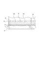
次に現像剤収納ユニット25の構成について図6、図7、図8を用いて述べる。ここで図6は可撓性容器である現像剤収納部材34の現像剤を排出する排出部35近傍の詳細断面図である。図7は現像剤収納容器30の断面からの斜視図である。図8は現像装置38の断面図である。なお、断面図は、開封部材20と、開口部35aと、固定部16と、を通る平面である。また、断面図は、開封部材20の回転軸に垂直な平面である。
[Example 2]
<Configuration outline of developer storage unit>
Next, the configuration of the
(現像剤収納ユニット)
図8に示すように、現像剤収納ユニット25は、現像ローラ13、現像ブレード15と、これらを支持する第一の枠体17と第二の枠体18から構成される。第一の枠体17と第二の枠体18を合わせたものが図7に示す現像剤収納容器30を収納する枠体である。図7に示すように、現像剤収納容器30は、現像剤収納部材34と、現像剤を排出するための開口部35aを封止するとともに移動されることによって開口部35aを露出する封止部材19から構成される。
(Developer storage unit)
As shown in FIG. 8, the
(現像剤を収納した現像剤収納容器)
図7に示すように、現像剤収納容器30は、現像剤と、現像剤収納部材34と、封止部材19から構成される。ここで現像剤は粉体である。
(Developer storage container containing developer)
As shown in FIG. 7, the
現像剤収納容器30の現像剤収納部材34は、図6及び図7に示すように、現像剤を排出する排出部が有する複数の開口部35aを封止部材19で封止している。このように現像剤を収納した現像剤収納容器30の開口部35aは封止されているため収納した現像剤を外に漏れず一つのユニットとして扱うことが可能である。
As shown in FIGS. 6 and 7, the
(現像剤収納部材の構成)
図7に示すように、現像剤収納部材34の構成は、真空成形、圧空成形、プレス成形により形つくられた可撓性を有する可撓性容器である成形部34aと、シート状の通気部34bから構成される。
(Configuration of developer storage member)
As shown in FIG. 7, the
成形部34aの素材としてABS・PMMA・PC・PP・PE・HIPS・PET・PVCなどや、これらの複合多層材料などが好ましい。また成形部34aの厚みは成形前のシート状の厚みで0.1〜1mm程度のものが好ましい。成形部34aの材料や厚みはコストや製品仕様、製造条件等により適宜選定すればよい。
ABS, PMMA, PC, PP, PE, HIPS, PET, PVC, or a composite multilayer material thereof is preferable as the material of the
ここで排出部(開口部35a)は成形部34aに設けられており、現像剤収納部材34の開封が進行する開封方向Eとする。なお封止部材19の材料構成、層構成は、実施例1と同じである。
Here, the discharge portion (opening
(開封部材の構成)
図6及び図7に示すように、開封部材20は、封止部材19の開封方向(矢印E方向)の一端側の自由端部に係合されており、封止部材19に力を与えて封止部材19を移動させ現像剤収納容器30から引き剥がす目的のものである。本実施例では開封部材20は、四角い軸形状で両端を枠体の内部に回転可能に支持されており、その四角い軸の一面に封止部材19の自由端部が係合されている。
(Configuration of opening member)
As shown in FIGS. 6 and 7, the unsealing
封止部材19は、装置本体Bからの駆動を受けて開封を自動的に行うようなものでもよい。または、ユーザが封止部材19を把持して移動させることで開封を行うようなものでもよい。本実施例では、前述したように、開封部材20は枠体に設けられた回転軸であり、開封部材20が矢印C方向に回転すると、開封部材20に係合された封止部材19が開封方向に引っ張られて現像剤収納容器30の開口部35aを開封する。
The sealing
(封止部材の易開封性を有する部分)
次に、図9と図10を用いて接合部22の剥離強度を所望の値にする封止部材19の配置方法について説明する。
(Part having the easy-opening property of the sealing member)
Next, an arrangement method of the sealing
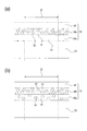
図10(a)は成形後のロール状の封止部材19を示す。このロール状の封止部材19は、相溶性材料51と非相溶性材料52を混練し、薄く引き伸ばしながら巻き取って成形する。この際、相溶性材料51と非相溶性材料52は柔らかい状態で引き伸ばされるため、この引き伸ばされる方向である延伸方向(MD)に伸びたような形に成形される。
Fig.10 (a) shows the roll-shaped sealing
このロール状の封止部材から切り出した封止部材19は、図9に示すように移動により開封方向(矢印E方向)に進むことで開口部35aを露出する。この開封方向Eに対し、図10(a)に示す封止部材19の延伸方向(矢印MD方向)が平行となるように封止部材19を配置する。これによって、開封時の単位時間あたりに発生するシーラント層の材料破壊の量が少なくなり、封止部材19の剥離強度が低くなる。
The sealing
この封止部材19の剥離強度が低くなる理由は以下の通りである。封止部材19のシーラント層39が有する非相溶性材料52は、前述したように延伸方向(矢印MD方向)に伸びている。そのため、封止部材19の開封方向(図9の矢印E方向)と延伸方向(図10(b)の矢印MD方向)を平行にした際の剥離ラインLa上に非相溶性材料52が存在する時間が、垂直方向(矢印TD方向)にした剥離ラインLb上よりも長くなる。その結果、剥離ラインLaの方がライン全体で非相溶性材料52が占める割合は高く、材料破壊が必要な相溶性材料51の占める割合が低くなる。このため、上記のように封止部材19を配置することで、実施例1の効果に加えて更に易開封とする効果が得られるようになる。なお、本実施例においては、JIS−Z0238の密封軟包装袋の試験に於いて開封方向Eに封止部材19を引いたときの剥離強度が3N/15mm程度のものを用いている。
The reason why the peel strength of the sealing
(可撓性を有する現像収納容器の効果)
可撓性を有する現像剤収納容器30に封止部材19を配する効果について、図11を用いて説明する。現像剤収納容器30が輸送時の振動など衝撃を受ける際に排出部35の開口部35aには現像剤によって封止部材19を剥がそうとする方向(矢印G方向)の力がかかる。この際、排出部35は可撓性を有し変形するため、接合部22にかかる力は剪断方向(矢印F方向)となり、排出部35が変形しない構成と比べて剥がれ難くなる。これにより、封止部材19は更に安定して密封性と開封性を両立させることが可能となる。
(Effect of developing container having flexibility)
The effect of disposing the sealing
〔他の実施例〕
前述した実施例では、相溶性材料51と非相溶性材料52の一方が他方の中で散在する状態として、封止部材19が、相溶性材料51中に非相溶性材料52が散在するシーラント層39を有する構成を例示したが、逆の構成であってもよい。すなわち、図12に示すように、封止部材19が、非相溶性材料52中に相溶性材料51が散在するシーラント層39を有する構成としてもよい。この構成で封止部材19を剥離すると、非相溶性材料52と現像剤収納容器30の界面で剥離するものの、相溶性材料51は現像剤収納容器30に固着している。そのため、図12に示す構成の封止部材19は、図4及び図5に示す界面剥離する封止部材とは異なり、図3に示す構成の封止部材19と同様に剥離強度を低く制御することができる。
[Other Examples]
In the above-described embodiment, the sealing
また前述した実施例では、封止部材19は、その一部であるシーラント層39が、1つの層である場合を例示したが、これに限定されるものではない。すなわち、封止部材19は、その一部であるシーラント層39が複数の層を有し、容器に接合する第1の層に対して、前記第1の層に隣接する第2の層は相溶性材料51および非相溶性材料52からなる構成であっても良い。例えば、図13(a)に示すように、シーラント層39が2つ層39a,39bを有する場合、容器に接合する第1の層39aが相溶性材料51のみからなり、その上の第2の層39bが相溶性材料51および非相溶性材料52からなる構成であっても良い。更に、その第2の層39bの上に補強層40を有する構成であっても良い。また、図13(b)に示すように、容器30に接合する第1の層39aとその上の第2の層39bの両方が、相溶性材料51および非相溶性材料52からなり、その上に補強層40を有する構成であっても良い。なお、図13(b)に示す構成では第2の層39bの方が第1の層39aよりも非相溶性材料52の割合を高くしている。このように、封止部材19の一部であるシーラント層39が複数の層を有する場合は、実施例1の構成により得られる効果に加えて、以下の効果が得られる。すなわち、容器と直接接合する第1の層ではなく、容器との接合の影響を受けない第2の層でシールが安定的に剥離されるので、密封性と開封性をさらに両立しやすくなる。
Moreover, in the Example mentioned above, although the sealing
また前述した実施例では、画像形成装置本体に対して着脱可能なプロセスカートリッジとして、感光体ドラムと、該感光体ドラムに作用するプロセス手段としての帯電手段,現像手段,クリーニング手段を一体に有するプロセスカートリッジを例示した。しなしながら、これに限定されるものではなく、感光体ドラムの他に、帯電手段、現像手段、クリーニング手段のうち、いずれか1つを一体に有するプロセスカートリッジであっても良い。 In the above-described embodiment, as a process cartridge that can be attached to and detached from the image forming apparatus main body, a process that integrally includes a photosensitive drum and a charging unit, a developing unit, and a cleaning unit as process units that act on the photosensitive drum. A cartridge was illustrated. However, the process cartridge is not limited to this, and may be a process cartridge integrally including any one of a charging unit, a developing unit, and a cleaning unit in addition to the photosensitive drum.
また前述した実施例では、画像形成装置としてプリンタを例示したが、本発明はこれに限定されるものではなく、例えば複写機、ファクシミリ装置等の他の画像形成装置や、或いはこれらの機能を組み合わせた複合機等の他の画像形成装置であっても良い。これらの画像形成装置に用いられる現像剤収納容器、現像剤収納ユニット、又はプロセスカートリッジに本発明を適用することにより同様の効果を得ることができる。 In the above-described embodiments, the printer is exemplified as the image forming apparatus. However, the present invention is not limited to this, and other image forming apparatuses such as a copying machine and a facsimile machine, or a combination of these functions. Other image forming apparatuses such as multifunction peripherals may also be used. The same effect can be obtained by applying the present invention to a developer storage container, a developer storage unit, or a process cartridge used in these image forming apparatuses.
A …プロセスカートリッジ
B …装置本体
11 …感光体ドラム
13 …現像ローラ
17 …第一の枠体
18 …第二の枠体
19 …封止部材
20 …開封部材
22 …接合部
24 …クリーナーユニット
25 …現像剤収納ユニット
30 …現像剤収納容器
34 …現像剤収納部材
35 …排出部
35a …開口部
38 …現像装置
39 …シーラント層
40 …補強層
51 …相溶性材料
52 …非相溶性材料
A ... Process cartridge B ... Device
Claims (27)
前記開口を封止し、開封方向に剥離されることによって前記開口を露出することが可能なシール部材を有し、
前記シール部材は、前記現像剤収納容器を構成する材料に対して相溶性を有する材料を含む層と、前記層の中に分散し前記現像剤収納容器を構成する材料に対して非相溶性を有する材料を含む複数の分散部と、前記現像剤収納容器の長手方向に伸びる前記現像剤収納容器と接合する接合部と、を有し、
前記分散部は、前記開封方向に延伸している形状を有し、
前記長手方向と前記開封方向が交差することを特徴とする現像剤収納容器。 A developer storage container having an opening for discharging the developer and storing the developer,
A seal member that seals the opening and is capable of exposing the opening by being peeled in the opening direction;
The seal member has a layer containing a material having compatibility with a material constituting the developer storage container, and is incompatible with a material dispersed in the layer and constituting the developer storage container. A plurality of dispersion portions including a material having, and a joint portion that joins the developer storage container extending in a longitudinal direction of the developer storage container ,
The dispersion part has a shape extending in the opening direction,
The developer storage container, wherein the longitudinal direction and the opening direction intersect .
前記開口を封止し、開封方向に剥離されることによって前記開口を露出することが可能なシール部材を有し、
前記シール部材は、前記現像剤収納容器を構成する材料に対して非相溶性を有する材料を含む層と、前記層の中に分散し前記現像剤収納容器を構成する材料に対して相溶性を有する材料を含む複数の分散部と、前記現像剤収納容器の長手方向に伸びる前記現像剤収納容器と接合する接合部と、を有し、
前記分散部は、前記開封方向に延伸している形状を有し、
前記長手方向と前記開封方向が交差することを特徴とする現像剤収納容器。 A developer storage container having an opening for discharging the developer and storing the developer,
A seal member that seals the opening and is capable of exposing the opening by being peeled in the opening direction;
The seal member is compatible with a material including a material that is incompatible with a material constituting the developer container, and a material dispersed in the layer and constituting the developer container. A plurality of dispersion portions including a material having, and a joint portion that joins the developer storage container extending in a longitudinal direction of the developer storage container ,
The dispersion part has a shape extending in the opening direction,
The developer storage container, wherein the longitudinal direction and the opening direction intersect .
前記第2の層は、前記相溶性を有する材料と前記非相溶性を有する材料とを有することを特徴とする請求項1から3のいずれか1項に記載の現像剤収納容器。 The seal member has a first layer and a second layer adjacent to the first layer;
4. The developer storage container according to claim 1, wherein the second layer includes the compatible material and the incompatible material. 5.
前記開封部材は、前記現像剤収納容器の長手方向に伸びていることを特徴とする請求項1から9のいずれか1項に記載の現像剤収納容器。The developer storage container according to claim 1, wherein the opening member extends in a longitudinal direction of the developer storage container.
請求項1から9のいずれか1項に記載の現像剤収納容器と、
前記現像剤収納容器を収納する枠体であって、前記現像剤収納容器から排出される現像剤を収納するための枠体と、
前記枠体の内部に設けられ前記現像剤収納容器の開口を封止するシール部材を剥離させ前記開口を露出する開封部材と、
を備えることを特徴とする現像剤収納ユニット。 A developer storage unit for storing the developer,
The developer container according to any one of claims 1 to 9,
A frame for storing the developer storage container, the frame for storing the developer discharged from the developer storage container;
An opening member that is provided inside the frame and peels off a sealing member that seals the opening of the developer container and exposes the opening;
A developer storage unit comprising:
更に、請求項1から9のいずれか1項に記載の現像剤収納容器、請求項10又は11に記載の現像剤収納ユニットの少なくとも1つを有することを特徴とする現像装置。A developing device comprising at least one of the developer storage container according to claim 1 and the developer storage unit according to claim 10 or 11.
更に、請求項12記載の現像装置の少なくとも1つを有することを特徴とするプロセスカートリッジ。 Having an image carrier for carrying a developer image;
13. A process cartridge comprising at least one developing device according to claim 12.
前記開口を封止し、開封方向に剥離されることによって前記開口を露出することが可能なシール部材を有し、 A seal member that seals the opening and is capable of exposing the opening by being peeled in the opening direction;
前記シール部材は、前記枠体を構成する材料に対して相溶性を有する材料を含む層と、前記層の中に分散し前記枠体を構成する材料に対して非相溶性を有する材料を含む複数の分散部と、前記枠体の長手方向に伸びる前記枠体と接合する接合部と、を有し、 The seal member includes a layer including a material having compatibility with a material constituting the frame body, and a material having an incompatibility with a material dispersed in the layer and constituting the frame body. A plurality of dispersed portions, and a joining portion that joins the frame extending in the longitudinal direction of the frame,
前記分散部は、前記開封方向に延伸している形状を有し、 The dispersion part has a shape extending in the opening direction,
前記長手方向と前記開封方向が交差することを特徴とする現像剤収納ユニット。The developer storage unit, wherein the longitudinal direction and the opening direction intersect.
前記開口を封止し、開封方向に剥離されることによって前記開口を露出することが可能なシール部材を有し、
前記シール部材は、前記枠体を構成する材料に対して非相溶性を有する材料を含む層と、前記層の中に分散し前記枠体を構成する材料に対して相溶性を有する材料を含む複数の分散部と、前記枠体の長手方向に伸びる前記枠体と接合する接合部と、を有し、
前記分散部は、前記開封方向に延伸している形状を有し、
前記長手方向と前記開封方向が交差することを特徴とする現像剤収納ユニット。 A frame having an opening and containing a developer;
A seal member that seals the opening and is capable of exposing the opening by being peeled in the opening direction;
The seal member includes a layer containing a material that is incompatible with the material constituting the frame, and a material that is dispersed in the layer and compatible with the material constituting the frame. A plurality of dispersed portions, and a joining portion that joins the frame extending in the longitudinal direction of the frame,
The dispersion part has a shape extending in the opening direction,
The developer storage unit, wherein the longitudinal direction and the opening direction intersect .
前記第2の層は、前記相溶性を有する材料と前記非相溶性を有する材料とを有することを特徴とする請求項15から17のいずれか1項に記載の現像剤収納ユニット。The developer storage unit according to claim 15, wherein the second layer includes the compatible material and the incompatible material.
前記開封部材は、前記枠体の長手方向に伸びていることを特徴とする請求項15から22のいずれか1項に記載の現像剤収納ユニット。The developer storage unit according to any one of claims 15 to 22, wherein the opening member extends in a longitudinal direction of the frame body.
請求項15から25のいずれか1項に記載の現像剤収納ユニットと、を有することを特徴とする現像装置。A developing device comprising: the developer storage unit according to any one of claims 15 to 25.
請求項25に記載の現像装置と、を有することを特徴とするプロセスカートリッジ。26. A process cartridge comprising the developing device according to claim 25.
Priority Applications (3)
| Application Number | Priority Date | Filing Date | Title |
|---|---|---|---|
| JP2013160961A JP5693678B2 (en) | 2012-09-10 | 2013-08-02 | Developer storage container, developer storage unit, process cartridge, image forming apparatus |
| CN201310398762.7A CN103676553B (en) | 2012-09-10 | 2013-09-05 | Developer accommodating container, developer accommodating unit, process cartridge and image forming apparatus |
| US14/018,485 US9304441B2 (en) | 2012-09-10 | 2013-09-05 | Developer accommodating container, developer accommodating unit, process cartridge and image forming apparatus |
Applications Claiming Priority (3)
| Application Number | Priority Date | Filing Date | Title |
|---|---|---|---|
| JP2012198056 | 2012-09-10 | ||
| JP2012198056 | 2012-09-10 | ||
| JP2013160961A JP5693678B2 (en) | 2012-09-10 | 2013-08-02 | Developer storage container, developer storage unit, process cartridge, image forming apparatus |
Publications (3)
| Publication Number | Publication Date |
|---|---|
| JP2014067007A JP2014067007A (en) | 2014-04-17 |
| JP2014067007A5 JP2014067007A5 (en) | 2014-08-21 |
| JP5693678B2 true JP5693678B2 (en) | 2015-04-01 |
Family
ID=50233401
Family Applications (1)
| Application Number | Title | Priority Date | Filing Date |
|---|---|---|---|
| JP2013160961A Active JP5693678B2 (en) | 2012-09-10 | 2013-08-02 | Developer storage container, developer storage unit, process cartridge, image forming apparatus |
Country Status (3)
| Country | Link |
|---|---|
| US (1) | US9304441B2 (en) |
| JP (1) | JP5693678B2 (en) |
| CN (1) | CN103676553B (en) |
Families Citing this family (21)
| Publication number | Priority date | Publication date | Assignee | Title |
|---|---|---|---|---|
| CN103649843B (en) | 2011-07-14 | 2018-04-13 | 佳能株式会社 | Developer-accommodating vessel, handle box, electro photography type imaging device |
| JP5420025B2 (en) | 2011-07-14 | 2014-02-19 | キヤノン株式会社 | Developer storage unit, process cartridge, electrophotographic image forming apparatus |
| JP6066841B2 (en) | 2012-09-10 | 2017-01-25 | キヤノン株式会社 | Developing cartridge, process cartridge, and image forming apparatus |
| JP5980061B2 (en) | 2012-09-11 | 2016-08-31 | キヤノン株式会社 | Developer container, process cartridge, and image forming apparatus |
| JP6120730B2 (en) | 2012-09-13 | 2017-04-26 | キヤノン株式会社 | Developer storage unit, process cartridge, image forming apparatus |
| JP6245932B2 (en) | 2012-11-06 | 2017-12-13 | キヤノン株式会社 | Cartridge, developing cartridge, process cartridge, and image forming apparatus |
| JP6202820B2 (en) | 2013-01-11 | 2017-09-27 | キヤノン株式会社 | Developer storage unit, developing device, process cartridge, and image forming apparatus |
| JP6112971B2 (en) | 2013-01-11 | 2017-04-12 | キヤノン株式会社 | Developer container, developing device, process cartridge, electrophotographic image forming apparatus |
| JP6116254B2 (en) | 2013-01-11 | 2017-04-19 | キヤノン株式会社 | Developer storage unit, developing device, process cartridge, image forming apparatus |
| JP6116253B2 (en) | 2013-01-11 | 2017-04-19 | キヤノン株式会社 | Developer storage unit, developing device, process cartridge, and image forming apparatus including the same |
| JP6282149B2 (en) | 2013-06-05 | 2018-02-21 | キヤノン株式会社 | Developer storage unit, developing device, process cartridge, and image forming apparatus |
| JP6173069B2 (en) | 2013-06-27 | 2017-08-02 | キヤノン株式会社 | Developer container, developer cartridge, process cartridge, and image forming apparatus |
| JP6381222B2 (en) | 2014-02-18 | 2018-08-29 | キヤノン株式会社 | Developer storage unit and manufacturing method thereof, developing device, process cartridge, and image forming apparatus |
| JP6138181B2 (en) | 2014-04-15 | 2017-05-31 | キヤノン株式会社 | Resin molded product and cartridge used for image forming apparatus, method for manufacturing movable member used for image forming apparatus, and method for manufacturing cartridge |
| CA3135768C (en) | 2015-02-27 | 2024-03-05 | Canon Kabushiki Kaisha | Drum unit, cartridge and coupling member |
| WO2017142099A1 (en) | 2016-02-18 | 2017-08-24 | Canon Kabushiki Kaisha | Cartridge and image forming apparatus |
| JP6752596B2 (en) * | 2016-03-14 | 2020-09-09 | キヤノン株式会社 | Developer container, cartridge, and image forming equipment |
| JP6753112B2 (en) * | 2016-03-31 | 2020-09-09 | ブラザー工業株式会社 | Developer cartridge and developer storage unit |
| JP6932521B2 (en) * | 2016-05-11 | 2021-09-08 | キヤノン株式会社 | cartridge |
| US9946199B1 (en) | 2016-09-23 | 2018-04-17 | Clover Technologies Group, Llc | System and method of filling a toner container |
| US10162288B2 (en) | 2016-09-23 | 2018-12-25 | Clover Technologies Group, Llc | System and method of remanufacturing a toner container |
Family Cites Families (46)
| Publication number | Priority date | Publication date | Assignee | Title |
|---|---|---|---|---|
| US5030998A (en) * | 1989-05-31 | 1991-07-09 | Mita Industrial Co., Ltd. | Toner cartridge having easily removable toner supply opening seal member |
| JPH0466980A (en) | 1990-07-04 | 1992-03-03 | Canon Inc | Developer supplying device |
| JP2989028B2 (en) * | 1991-03-20 | 1999-12-13 | キヤノン株式会社 | Developer container |
| JPH07209976A (en) | 1994-01-19 | 1995-08-11 | Canon Inc | Toner storing device, developing device process cartridge and image forming device |
| JP3437340B2 (en) * | 1995-07-20 | 2003-08-18 | キヤノン株式会社 | Image forming apparatus, process cartridge, and developing apparatus |
| JPH09111060A (en) * | 1995-10-13 | 1997-04-28 | Nippon Tetrapack Kk | Readily tearable film |
| US6097907A (en) | 1996-10-02 | 2000-08-01 | Canon Kabushiki Kaisha | Developer container, process cartridge, developer sealing member and sealing method |
| JP3579701B2 (en) * | 1997-02-24 | 2004-10-20 | チッソ株式会社 | Polypropylene-based uniaxially stretched film |
| JP3563943B2 (en) * | 1997-12-02 | 2004-09-08 | キヤノン株式会社 | Developer container and process cartridge |
| JP4088996B2 (en) * | 1998-02-06 | 2008-05-21 | 東洋製罐株式会社 | Multi-room pouch |
| JP3486551B2 (en) * | 1998-03-20 | 2004-01-13 | キヤノン株式会社 | Developer container and process cartridge |
| US6128462A (en) | 1998-04-02 | 2000-10-03 | Canon Kabushiki Kaisha | Cleaning member, image forming apparatus provided with a cleaning blade member, and process cartridge detachably attachable on the image forming apparatus |
| US6175703B1 (en) | 1998-10-23 | 2001-01-16 | Canon Kabushiki Kaisha | Image forming apparatus and process cartridge |
| US6169869B1 (en) | 1999-01-28 | 2001-01-02 | Canon Kabushiki Kaisha | Image forming apparatus and process cartridge |
| JP3768712B2 (en) | 1999-02-09 | 2006-04-19 | キヤノン株式会社 | Stirring means, developing device, and process cartridge |
| JP2001034055A (en) * | 1999-02-18 | 2001-02-09 | Canon Inc | Developer container and cartridge |
| JP2001296740A (en) * | 2000-02-18 | 2001-10-26 | Canon Inc | Developer container, process cartridge, and developer container sealing method |
| JP2001242684A (en) | 2000-03-01 | 2001-09-07 | Canon Inc | Image forming device and process cartridge |
| JP2002055517A (en) * | 2000-08-09 | 2002-02-20 | Katsuragawa Electric Co Ltd | Developing device |
| JP3566697B2 (en) | 2001-02-09 | 2004-09-15 | キヤノン株式会社 | Process cartridge, electrophotographic image forming apparatus, and separation mechanism |
| US6834173B2 (en) | 2001-11-05 | 2004-12-21 | Canon Kabushiki Kaisha | Image-forming-apparatus process cartridge having a locking portion to prevent the cartridge from disengaging from the image forming apparatus and an image forming apparatus mounting such a cartridge |
| JP2003307931A (en) | 2002-04-17 | 2003-10-31 | Canon Inc | Process cartridge and electrophotographic image forming apparatus |
| JP3728267B2 (en) | 2002-04-23 | 2005-12-21 | キヤノン株式会社 | Process cartridge and image forming apparatus |
| JP3684209B2 (en) | 2002-05-31 | 2005-08-17 | キヤノン株式会社 | Cartridge and electrophotographic image forming apparatus |
| US6947687B2 (en) | 2002-06-07 | 2005-09-20 | Canon Kabushiki Kaisha | Cartridge having locking portion for locking cartridge with an image forming apparatus and releasing portion to release the locking portion, and image forming apparatus having such a cartridge |
| JP3745327B2 (en) | 2002-09-30 | 2006-02-15 | キヤノン株式会社 | Process cartridge remanufacturing method |
| JP3809412B2 (en) | 2002-09-30 | 2006-08-16 | キヤノン株式会社 | Developing cartridge and electrophotographic image forming apparatus |
| JP3542588B2 (en) | 2002-09-30 | 2004-07-14 | キヤノン株式会社 | Developing cartridge, mounting method of one end side cover, mounting method of other end side cover, and electrophotographic image forming apparatus |
| JP4422991B2 (en) * | 2003-08-29 | 2010-03-03 | キヤノン株式会社 | Developing device, process cartridge, and electrophotographic image forming apparatus |
| DE10352430A1 (en) * | 2003-11-10 | 2005-06-09 | Mitsubishi Polyester Film Gmbh | Peelable polyester film with improved oxygen barrier, process for its preparation and its use |
| JP4343668B2 (en) | 2003-12-11 | 2009-10-14 | キヤノン株式会社 | Developing device, cartridge, and image forming apparatus |
| JP4110143B2 (en) | 2004-01-30 | 2008-07-02 | キヤノン株式会社 | Electrophotographic image forming apparatus, unit detachable from electrophotographic image forming apparatus, and process cartridge |
| JP4378299B2 (en) | 2004-02-20 | 2009-12-02 | キヤノン株式会社 | Process cartridge and electrophotographic image forming apparatus |
| JP4040636B2 (en) | 2005-03-24 | 2008-01-30 | キヤノン株式会社 | Process cartridge and electrophotographic image forming apparatus |
| JP2011123348A (en) | 2009-12-11 | 2011-06-23 | Canon Inc | Process cartridge and method for disassembling process cartridge |
| JP5697420B2 (en) * | 2010-01-13 | 2015-04-08 | キヤノン株式会社 | Cartridge and image forming apparatus |
| JP2011197063A (en) * | 2010-03-17 | 2011-10-06 | Ricoh Co Ltd | Toner cartridge, process cartridge and image forming apparatus |
| US8932725B2 (en) * | 2010-07-29 | 2015-01-13 | Toray Plastics (America), Inc. | Heat sealable film with linear tear properties |
| JP2012088655A (en) * | 2010-10-22 | 2012-05-10 | Canon Inc | Process cartridge and image forming device |
| WO2013008953A1 (en) | 2011-07-14 | 2013-01-17 | キヤノン株式会社 | Developer housing unit, process cartridge, and electrophotographic image forming device |
| CN103649843B (en) | 2011-07-14 | 2018-04-13 | 佳能株式会社 | Developer-accommodating vessel, handle box, electro photography type imaging device |
| JP5420025B2 (en) | 2011-07-14 | 2014-02-19 | キヤノン株式会社 | Developer storage unit, process cartridge, electrophotographic image forming apparatus |
| JP5808233B2 (en) | 2011-11-29 | 2015-11-10 | キヤノン株式会社 | Developer storage unit, developing device, process cartridge, electrophotographic image forming apparatus |
| JP5911275B2 (en) | 2011-11-29 | 2016-04-27 | キヤノン株式会社 | Developer storage unit, developing device, process cartridge, electrophotographic image forming apparatus |
| JP5771797B2 (en) | 2011-11-29 | 2015-09-02 | キヤノン株式会社 | Developing device, cartridge, and electrophotographic image forming apparatus |
| JP6053404B2 (en) | 2012-06-15 | 2016-12-27 | キヤノン株式会社 | Developer storage unit, developing device, process cartridge, electrophotographic image forming apparatus |
-
2013
- 2013-08-02 JP JP2013160961A patent/JP5693678B2/en active Active
- 2013-09-05 US US14/018,485 patent/US9304441B2/en active Active
- 2013-09-05 CN CN201310398762.7A patent/CN103676553B/en active Active
Also Published As
| Publication number | Publication date |
|---|---|
| JP2014067007A (en) | 2014-04-17 |
| CN103676553A (en) | 2014-03-26 |
| US20140072331A1 (en) | 2014-03-13 |
| CN103676553B (en) | 2017-01-11 |
| US9304441B2 (en) | 2016-04-05 |
Similar Documents
| Publication | Publication Date | Title |
|---|---|---|
| JP5693678B2 (en) | Developer storage container, developer storage unit, process cartridge, image forming apparatus | |
| JP5420025B2 (en) | Developer storage unit, process cartridge, electrophotographic image forming apparatus | |
| JP5420026B2 (en) | Developer storage container, developer storage unit, process cartridge, electrophotographic image forming apparatus | |
| JP5420024B2 (en) | Developer storage container, developer storage unit, process cartridge, electrophotographic image forming apparatus | |
| EP2733547B1 (en) | Developer housing unit, process cartridge, and electrophotographic image forming device | |
| US9285707B2 (en) | Developer accommodating unit with a urging member for urging a flexible member | |
| JP2014056045A (en) | Developer storage unit, process cartridge, and electrophotography image forming device | |
| US9146503B2 (en) | Developer accommodating unit, process cartridge and electrophotographic image forming apparatus | |
| JP2014056025A (en) | Developer storage container, process cartridge, and image forming apparatus | |
| EP3492993A1 (en) | Developer accommodating member, developer accommodating unit, developing device, process cartridge and image forming apparatus | |
| JP6433558B2 (en) | Developer container, developing device, process cartridge, and image forming apparatus | |
| JP6045477B2 (en) | Developer storage container, developer storage unit, process cartridge, electrophotographic image forming apparatus | |
| JP6049590B2 (en) | Developer storage container, developer storage unit, process cartridge, electrophotographic image forming apparatus | |
| JP5921167B2 (en) | Developer storage unit, developing device, process cartridge, electrophotographic image forming apparatus | |
| JP2015108683A (en) | Container, developer container, developer storage unit, process cartridge, and image forming apparatus | |
| JP5921166B2 (en) | Developer storage unit, process cartridge, electrophotographic image forming apparatus | |
| JP2015200837A (en) | Developer storage unit, process cartridge, and image forming apparatus |
Legal Events
| Date | Code | Title | Description |
|---|---|---|---|
| A521 | Request for written amendment filed |
Free format text: JAPANESE INTERMEDIATE CODE: A523 Effective date: 20140703 |
|
| A621 | Written request for application examination |
Free format text: JAPANESE INTERMEDIATE CODE: A621 Effective date: 20140703 |
|
| A871 | Explanation of circumstances concerning accelerated examination |
Free format text: JAPANESE INTERMEDIATE CODE: A871 Effective date: 20140703 |
|
| A975 | Report on accelerated examination |
Free format text: JAPANESE INTERMEDIATE CODE: A971005 Effective date: 20140815 |
|
| A131 | Notification of reasons for refusal |
Free format text: JAPANESE INTERMEDIATE CODE: A131 Effective date: 20140819 |
|
| A521 | Request for written amendment filed |
Free format text: JAPANESE INTERMEDIATE CODE: A523 Effective date: 20141016 |
|
| TRDD | Decision of grant or rejection written | ||
| A01 | Written decision to grant a patent or to grant a registration (utility model) |
Free format text: JAPANESE INTERMEDIATE CODE: A01 Effective date: 20150106 |
|
| A61 | First payment of annual fees (during grant procedure) |
Free format text: JAPANESE INTERMEDIATE CODE: A61 Effective date: 20150203 |
|
| R151 | Written notification of patent or utility model registration |
Ref document number: 5693678 Country of ref document: JP Free format text: JAPANESE INTERMEDIATE CODE: R151 |