JP5692505B2 - Liquid ejector - Google Patents
Liquid ejector Download PDFInfo
- Publication number
- JP5692505B2 JP5692505B2 JP2010226784A JP2010226784A JP5692505B2 JP 5692505 B2 JP5692505 B2 JP 5692505B2 JP 2010226784 A JP2010226784 A JP 2010226784A JP 2010226784 A JP2010226784 A JP 2010226784A JP 5692505 B2 JP5692505 B2 JP 5692505B2
- Authority
- JP
- Japan
- Prior art keywords
- liquid ejecting
- paper
- rib
- ejecting apparatus
- liquid
- Prior art date
- Legal status (The legal status is an assumption and is not a legal conclusion. Google has not performed a legal analysis and makes no representation as to the accuracy of the status listed.)
- Active
Links
Images


Description
本発明は、例えば紙製の記録媒体に液体を噴射する液体噴射装置に関する。 The present invention relates to a liquid ejecting apparatus that ejects liquid onto, for example, a paper recording medium.
記録媒体に液体を噴射する液体噴射装置の一例として、記録媒体としての記録用紙に液体であるインクを噴射するインクジェット式プリンターが知られている。インクジェット式プリンターには、複数のノズルが形成されたノズル形成面を有する液体噴射ヘッドと、記録用紙を液体噴射ヘッドのノズル形成面と対向した状態に支持する支持部材とが備えられている。そして、液体噴射ヘッドと記録用紙とが相対的に移動しながら、ノズル形成面と対向する対向位置に位置する記録用紙に向けて液体噴射ヘッドのノズルからインク滴が噴射されることによって、記録用紙に文字や図形などが記録される。 As an example of a liquid ejecting apparatus that ejects liquid onto a recording medium, an ink jet printer that ejects ink that is liquid onto recording paper serving as a recording medium is known. The ink jet printer includes a liquid ejecting head having a nozzle forming surface on which a plurality of nozzles are formed, and a support member that supports the recording paper in a state of facing the nozzle forming surface of the liquid ejecting head. Then, while the liquid ejecting head and the recording paper are relatively moved, the ink droplets are ejected from the nozzles of the liquid ejecting head toward the recording paper located at the facing position facing the nozzle forming surface, so that the recording paper Characters and figures are recorded in
ところで、記録媒体が紙製の記録用紙である場合には、搬送時における記録用紙の振動や記録用紙と他の部材との接触などによって記録用紙から粉塵の一種である紙粉が飛散する。特に、紙繊維が強制的に切断されてなる記録用紙の裁断面からは、上述したような記録用紙の挙動によって紙粉が飛散しやすい。そのため、支持部材に向けて搬送される記録用紙の搬送方向下流側の端部が支持部材に設けられたリブに衝突するとなれば、該先端における裁断面から多くの紙粉が飛散することになる。そして、飛散した紙粉が記録用紙の周辺を浮遊してその一部がノズルの近傍に付着する結果、ノズルから噴射されるインク滴の飛行する方向が変化したり、ノズルが紙粉によって塞がれるといったノズル詰まりが発生したりする。 By the way, when the recording medium is a paper recording paper, paper dust, which is a kind of dust, is scattered from the recording paper due to vibration of the recording paper during conveyance, contact between the recording paper and another member, or the like. In particular, paper powder tends to scatter due to the behavior of the recording paper as described above from the cut surface of the recording paper in which the paper fibers are forcibly cut. For this reason, if the end of the recording sheet conveyed toward the support member on the downstream side in the conveyance direction collides with a rib provided on the support member, a large amount of paper dust is scattered from the cut surface at the tip. . As a result of the scattered paper dust floating around the recording paper and a part of the paper dust adhering to the vicinity of the nozzle, the flying direction of the ink droplets ejected from the nozzle changes or the nozzle is blocked by the paper dust. Nozzle clogging may occur.
そこで特許文献1では、飛散した紙粉がノズルに付着することを抑えるために、液体噴射ヘッドを移動させるキャリッジに設けられたファンによって、記録用紙に対し、キャリッジの斜め往動方向に向けてエアーを吹き付けるという提案がなされている。この特許文献1に記載の装置によれば、エアーが吹き付けられた領域、すなわち飛散した紙粉がエアーによって吹き飛ばされた領域に向けてキャリッジが移動していくため、記録用紙から飛散した紙粉がノズル形成面に付着することが抑制される。 Therefore, in Patent Document 1, in order to prevent the scattered paper dust from adhering to the nozzles, air is directed toward the oblique forward direction of the carriage with respect to the recording paper by a fan provided in the carriage that moves the liquid ejecting head. The proposal of spraying is made. According to the apparatus described in Patent Document 1, since the carriage moves toward a region where air is blown, that is, a region where scattered paper dust is blown off by air, the paper dust scattered from the recording paper is reduced. Adhesion to the nozzle forming surface is suppressed.
ところで、記録用紙が支持部材に支持されて搬送される際には、記録用紙と支持部材との摩擦によって記録用紙や支持部材が帯電する。そして通常、記録ヘッドのノズル形成面は金属製のノズルプレートで構成されると共に、そのノズルプレートは接地されていることから、接地されたノズルプレートと帯電した支持部材との間での電位差によりノズルプレートと支持部材との間に電界が発生する。このため、支持部材が例えば負に帯電した場合には、支持部材とノズルプレートとの間で発生した電界によって、支持部材と同極性の紙粉がノズルプレートに誘導されてノズルプレートに吸着するという静電吸着が発生する。上述のエアーの吹き付けを通じて記録用紙から飛散した紙粉を一旦吹き飛ばしたとしても、吹き飛ばされた紙粉の位置を気流によって定めることは難しく、上述した電界が支持部材とノズルプレートとの間に発生する以上、吹き飛ばされた紙粉の一部も少なからず電界に誘導されてノズルプレートに付着することになってしまう。すなわち、ノズル近傍に対する紙粉の付着をエアーの吹き付けを通じて抑制したとしても、上述した電界による紙粉の付着が残る以上、記録用紙への印刷不良を抑制する上ではなお改良の余地を残すものとなっている。 By the way, when the recording paper is supported by the support member and conveyed, the recording paper and the support member are charged by friction between the recording paper and the support member. Usually, the nozzle forming surface of the recording head is composed of a metal nozzle plate, and the nozzle plate is grounded. Therefore, the nozzle is caused by a potential difference between the grounded nozzle plate and the charged support member. An electric field is generated between the plate and the support member. For this reason, when the support member is negatively charged, for example, an electric field generated between the support member and the nozzle plate induces paper powder having the same polarity as that of the support member to be adsorbed to the nozzle plate. Electrostatic adsorption occurs. Even if the paper dust scattered from the recording paper is blown once through the above-described air blowing, it is difficult to determine the position of the blown paper dust by the air flow, and the above-described electric field is generated between the support member and the nozzle plate. As described above, a part of the blown paper dust is not a little, but is induced by the electric field and adheres to the nozzle plate. That is, even if paper dust adhesion to the vicinity of the nozzles is suppressed by blowing air, as long as paper dust adheres due to the electric field described above, there is still room for improvement in suppressing printing defects on recording paper. It has become.
本発明は、このような実情に鑑みてなされたものであり、その目的は、記録媒体から粉塵が発生する虞のある場合において、そのような粉塵が液体噴射ヘッドに付着することを抑制することができる液体噴射装置を提供することにある。 The present invention has been made in view of such circumstances, and an object thereof is to suppress adhesion of such dust to the liquid ejecting head when dust may be generated from the recording medium. An object of the present invention is to provide a liquid ejecting apparatus that can
上記目的を達成するために、本発明の液体噴射装置は、記録媒体を支持する支持面を有する支持部材と、前記支持部材に対向するように配置されるとともに前記記録媒体の表面に対して液体を噴射する液体噴射ヘッドと、を備え、前記記録媒体が支持される領域の一部分には導電部材が設けられるとともに、前記導電部材は接地されている。 In order to achieve the above object, a liquid ejecting apparatus according to the present invention includes a support member having a support surface for supporting a recording medium, and a liquid disposed with respect to the surface of the recording medium. A conductive member is provided in a part of the area where the recording medium is supported , and the conductive member is grounded.
この発明によれば、導電部材が接地されることで、支持部材の支持面上に搬送された記録媒体と支持面との間で生じる摩擦により支持面が帯電し、そのように帯電した支持面と、接地された導電部材との間に電界が形成される。すると、記録媒体が粉塵を発生する虞のあるものであっても、その記録媒体の搬送時における記録媒体と支持部材との接触により記録媒体から飛散する粉塵が、支持面と導電部材との間に形成された電界により誘導されて導電部材に静電吸着される。よって、飛散した粉塵が液体噴射ヘッドに静電吸着されることが抑制され、液体噴射ヘッドに対する粉塵の付着を抑制することができる。 According to the present invention, when the conductive member is grounded, the support surface is charged by friction generated between the recording medium conveyed on the support surface of the support member and the support surface, and the support surface thus charged is charged. And an electric field formed between the grounded conductive member. Then, even if the recording medium may generate dust, the dust scattered from the recording medium due to the contact between the recording medium and the support member during conveyance of the recording medium is between the support surface and the conductive member. And is electrostatically attracted to the conductive member. Therefore, the scattered dust is suppressed from being electrostatically attracted to the liquid ejecting head, and the adhesion of the dust to the liquid ejecting head can be suppressed.
本発明の液体噴射装置において、前記支持部材は、前記支持面を有するとともに前記液体噴射ヘッドに向かって突出するリブを備え、前記導電部材は前記リブの側面に設けられている。 In the liquid ejecting apparatus according to the aspect of the invention, the support member includes a rib that has the support surface and protrudes toward the liquid ejecting head, and the conductive member is provided on a side surface of the rib.
この発明によれば、帯電する支持面と導電部材との間の距離を可能な限り短くすることができ、飛散した粉塵が導電部材に静電吸着され易くすることができる。
本発明の液体噴射装置は、前記導電部材における前記支持面側の縁部が前記支持面から離間している。
According to the present invention, the distance between the supporting surface to be charged and the conductive member can be shortened as much as possible, and the scattered dust can be easily electrostatically adsorbed to the conductive member.
In the liquid ejecting apparatus according to the aspect of the invention, an edge portion on the support surface side of the conductive member is separated from the support surface.
この発明によれば、例えば、導電部材の支持面側の縁部が、支持面と同一平面上に位置している場合に、記録媒体が導電部材の支持面側の縁部に衝突してしまい、記録媒体から粉塵が飛散してしまうといった問題を回避することができる。
本発明の液体噴射装置において、前記導電部材は、前記記録媒体の搬送方向において、前記液体噴射ヘッドが前記支持部材と対向する側に備える被接地部材の端部よりも上流側に設けられている。
本発明の液体噴射装置において、前記液体噴射ヘッドは、前記支持部材と対向する側に、接地された被接地部材を備え、前記支持面と前記導電部材との距離は、前記支持面と前記被接地部材との距離よりも短い。
According to this invention, for example, when the edge on the support surface side of the conductive member is located on the same plane as the support surface, the recording medium collides with the edge on the support surface side of the conductive member. The problem of dust scattering from the recording medium can be avoided.
In the liquid ejecting apparatus according to the aspect of the invention, the conductive member is provided on the upstream side of the end portion of the grounded member provided on the side where the liquid ejecting head faces the support member in the conveyance direction of the recording medium. .
In the liquid ejecting apparatus according to the aspect of the invention, the liquid ejecting head includes a grounded member that is grounded on a side facing the support member, and the distance between the support surface and the conductive member is the distance between the support surface and the supported member. It is shorter than the distance to the grounding member.
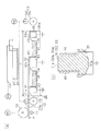
以下、本発明を液体噴射装置の一種であるインクジェット式プリンターに具体化した一実施形態を図1及び図2にしたがって説明する。
図1(a)に示すように、インクジェット式プリンターは、記録媒体としての記録用紙Pを搬送するための給紙ローラー10、リタードローラー11、紙送りローラー12及び排紙ローラー13を備えている。これら各ローラー10,11,12,13は、円柱状に形成されるとともに、その中心を回転軸として回動可能に配置されている。
Hereinafter, an embodiment in which the present invention is embodied in an ink jet printer which is a kind of liquid ejecting apparatus will be described with reference to FIGS. 1 and 2.
As shown in FIG. 1A, the ink jet printer includes a
給紙ローラー10は給紙モーターM1に連結されるとともに、この給紙モーターM1の駆動を通じて回転される(図1(a)では、給紙モーターM1の動力伝達経路を破線で図示)。この給紙ローラー10と対向するように配置されたリタードローラー11は、トルクリミッター等のトルク制限機構によって一定の回転負荷が付与された状態で従動回転する。そして、給紙モーターM1によって給紙ローラー10が回転することにより、給紙ローラー10とリタードローラー11との間に介在する記録用紙Pが紙送りローラー12に向けて搬送される。
The
紙送りローラー12は紙送りモーターM2に連結された搬送駆動ローラー12aと、搬送駆動ローラー12aに対向するように配置されて従動回転可能な搬送従動ローラー12bとによって構成される。また、排紙ローラー13は紙送りモーターM2に連結された排紙駆動ローラー13aと、排紙駆動ローラー13aに対向するように配置されて従動回転可能な排紙従動ローラー13bとによって構成される(図1(a)では、紙送りモーターM2の動力伝達経路を破線で図示)。
The
こうした紙送りローラー12及び排紙ローラー13では、紙送りモーターM2によって搬送駆動ローラー12a及び排紙駆動ローラー13aが回転駆動されることによって、それぞれ搬送従動ローラー12b及び排紙従動ローラー13bが協働して記録用紙Pの紙送り及び排紙を行う。なお、記録用紙Pが搬送される方向、すなわち紙送りローラー12から排紙ローラー13に向かう方向を、以下では搬送方向とする。
In the
また、紙送りローラー12と排紙ローラー13との間に搬送された記録用紙Pの上方には、インクカートリッジを搭載したキャリッジ20が紙面と垂直な方向、すなわち走査方向に移動可能に設けられている。キャリッジ20は、タイミングベルトを介してキャリッジモーターM3に連結されるとともに、このキャリッジモーターM3の駆動によって往復移動される(図1(a)では、キャリッジモーターM3の動力伝達経路を破線で図示)。また、キャリッジ20には、液体噴射ヘッドとしての記録ヘッド21が搭載されている。記録ヘッド21の下面には、下方に向けてインク滴を噴射する多数のノズル孔(図示略)が形成された金属製のノズルプレート22が設けられている。なお、このノズルプレート22は、その帯電を抑制すべく接地されていると共に、その下面がノズル形成面として機能する。
Also, above the recording paper P conveyed between the
紙送りローラー12と排紙ローラー13との間に搬送された記録用紙Pの下方には、記録用紙Pを支持する支持部材30が配置されている。支持部材30は、搬送される記録用紙Pとの摩擦によって負に帯電する絶縁性の樹脂材料によって形成されている。支持部材30は、本体30aと、本体30aから記録ヘッド21に向かって突出するとともに搬送方向に沿って順に並設される第1リブ31、第2リブ32及び第3リブ33を備えている。
A
図1(b)に示すように、各リブ31,32,33は本体30aと一体的に設けられるとともに、各リブ31,32,33の上面は平坦面状に形成されている。そして、この上面は記録用紙Pをノズル形成面と対向した状態に支持する支持面31a,32a,33aになっている。なお、図1(a)に示すように、支持部材30の上方の領域であって、搬送方向後方(上流側)における支持部材30の端部と、搬送方向前方(下流側)における支持部材30の端部とに挟まれる領域を、以下では印刷領域Rとする。
As shown in FIG. 1B, the
本体30aには、ノズルプレート22の搬送方向における両端部と対向する位置に、第1リブ31及び第2リブ32に挟まれる第1凹部34と、第2リブ32及び第3リブ33に挟まれる第2凹部35とが形成されている。これら第1凹部34及び第2凹部35には、インクを吸収して保持可能な第1吸収材36及び第2吸収材37が配設されている。これら第1吸収材36及び第2吸収材37は、例えば、液体を含浸したポリエチレンやポリウレタン等の多孔質部材である。そして、記録用紙Pの縁外までインクを噴射する縁無し印刷が実行される場合には、記録用紙Pの縁外に打ち捨てられたインク滴が第1凹部34又は第2凹部35に着弾して第1吸収材36及び第2吸収材37に回収される。
The
各リブ31,32,33の搬送方向に沿った両側面には、導電部材としての板金40が取り付けられている。各板金40は、各リブ31,32,33の突出方向において、各支持面31a,32a,33aと重合するように設けられている。図1(b)に示すように、各板金40の各支持面31a,32a,33a側の側縁部は、各支持面31a,32a,33aから離間するとともに、各板金40は接地されている。
このように構成されるプリンターでは、記録用紙Pの印刷時において、まず、給紙モーターM1が駆動されると、複数枚の記録用紙Pが搬送経路に沿って順次搬送される。次に、記録用紙Pが第1リブ31の支持面31aに支持されながら印刷領域Rに差し掛かると、記録ヘッド21の各ノズル孔からインク滴が噴射されて記録用紙Pに印刷が施される。
In the printer configured as described above, when the recording paper P is printed, first, when the paper feed motor M1 is driven, a plurality of recording papers P are sequentially transported along the transport path. Next, when the recording paper P reaches the printing region R while being supported by the
図2(a)に示すように、記録用紙Pの搬送時において記録用紙Pの裁断面である搬送方向下流側の端部である前端Pfが第1リブ31に衝突すると、記録用紙Pの前端Pfから粉塵の一例である紙粉Pdが飛散する。また、記録用紙Pが搬送される際に記録用紙Pと第1リブ31の支持面31aとの間では摩擦が発生し、この摩擦によって第1リブ31の支持面31aは負に帯電する。さらに、記録用紙Pから発生する紙粉Pdも、第1リブ31との衝突や摩擦により帯電した状態となる。このため、第1リブ31と記録用紙Pの前端Pfとの衝突によって飛散した紙粉Pdは、電荷を帯びた状態で第1リブ31とノズルプレート22との間を浮遊する。
As shown in FIG. 2A, when the front end Pf, which is the end portion on the downstream side in the transport direction, which is the cut surface of the recording paper P, collides with the
そして、図2(b)に示すように、負に帯電した第1リブ31の支持面31aと、接地された板金40との間には電界E1が形成される(図2(b)では、電界E1の向きを太線の電気力線によって示す)。また、負に帯電した第1リブ31の支持面31aと、接地されたノズルプレート22との間に電界E2が形成される(図2(b)では電界E2の向きを細線の電気力線によって示す)。
Then, as shown in FIG. 2B, an electric field E1 is formed between the negatively charged
ここで、第1リブ31の支持面31aと板金40との間の距離は、第1リブ31の支持面31aとノズルプレート22の下面との間の距離よりも短い。よって、板金40とノズルプレート22とが同電位であれば、電界E1は電界E2よりも強い(E1>E2)。このため、第1リブ31との衝突によって飛散して負に帯電した紙粉Pdnは、第1リブ31の支持面31aを基点として2方向に分散された電界E1及び電界E2のうちの電界強度が強い電界E1に支配的に誘導されて板金40に静電吸着される。なお、第1リブ31との衝突によって飛散して正に帯電した紙粉Pdpは、電界E1及び電界E2のいずれによっても、ノズルプレート22に引き寄せられないため、ノズルプレート22と記録用紙Pとの間を浮遊するか、又は記録用紙Pに付着する。
Here, the distance between the
その後、記録用紙Pは搬送される途中で、第1リブ31と同様に、その前端Pfが第2リブ32及び第3リブ33にも衝突し、前端Pfから紙粉Pdが飛散するが、飛散して負に帯電した紙粉Pdnは、上記説明と同様にして、第2リブ32及び第3リブ33に取り付けられた板金40に静電吸着される。このようにして、記録用紙Pは、上流側から下流側に搬送されながら順次印刷される。
Thereafter, while the recording paper P is being conveyed, the front end Pf collides with the
上記実施形態では以下の効果を得ることができる。
(1)上記実施形態によれば、各板金40が接地されることにより各リブ31,32,33の支持面31a,32a,33aを基点とする電界が分散される。このため、記録用紙Pの前端Pfが各リブ31,32,33に衝突したことによって紙粉Pdが飛散したとしても、負に帯電した紙粉Pdnが各板金40に向かって支配的に誘導される分、ノズルプレート22に紙粉Pdnが集中して吸着してしまうことを抑制することができる。その結果、ノズル詰まり等に起因するインクの噴射不良が抑制されるようになる。
In the above embodiment, the following effects can be obtained.
(1) According to the above embodiment, the electric fields having the base points of the support surfaces 31a, 32a, 33a of the
(2)板金40は、各リブ31,32,33の両側面に設けられている。よって、例えば、板金40が各吸収材36,37の下方に配置されている場合に比べて、各支持面31a,32a,33aと板金40との間の距離を短くすることができ、飛散して負に帯電した紙粉Pdnを板金40に静電吸着し易くすることができる。
(2) The
(3)各板金40の各支持面31a,32a,33a側の側縁部は、各支持面31a,32a,33aから離間している。よって、例えば、各板金40の各支持面31a,32a,33a側の側縁部が、各支持面31a,32a,33aと同一平面上に位置している場合に、記録用紙Pの前端Pfが板金40の各支持面31a,32a,33a側の側縁部に衝突してしまい、前端Pfから紙粉Pdが飛散してしまうといった問題を回避することができる。
(3) The side edge portions on the support surfaces 31a, 32a, 33a side of the
(4)板金40は、各リブ31,32,33の両側面に取り付けられている。よって、板金40が各リブ31,32,33の片側の側面にのみ取り付けられている場合に比べて、負に帯電した紙粉Pdnを板金40に静電吸着させる吸着力を増大させることができる。
(4) The
(5)板金40は、各リブ31,32,33の両側面に取り付けられている。よって、板金40を取り付ける位置が各リブ31,32,33の両側面のみであるため、支持部材30の側面全面に板金40を設ける場合に比べて、板金40を取り付ける作業を容易にすることができる。
(5) The
なお、上記実施形態は以下のような別の実施形態に変更してもよい。
・ 実施形態において、板金40が各リブ31,32,33の内部に埋設されていてもよい。例えば、図3(a)及び(b)に示すように、各リブ31,32,33には、各支持面31a,32a,33aから本体30a側に向かって凹む凹部51が形成されている。各凹部51には、板金40が各支持面31a側から各凹部51に挿入可能になっている。板金40が凹部51に挿入された状態において、板金40の各支持面31a,32a,33a側の側縁部は、凹部51の開口側から外方へ臨んだ状態になっている。
The above embodiment may be changed to another embodiment as described below.
-In embodiment, the
・ 実施形態において、各板金40の各支持面31a,32a,33a側の側縁部は、各支持面31a,32a,33aと同一平面上に位置していてもよい。
・ 実施形態において、板金40は、各リブ31,32,33の片側の側面にのみ取り付けられていてもよい。
-In embodiment, the side edge part by the side of each
-In embodiment, the
・ 実施形態において、板金40は、例えば、各リブ31,32,33の側面と本体30aの側面とを跨ぐようにして取り付けられていてもよい。
・ 実施形態において、板金40は、各リブ31,32,33の両側面に加えて、各支持面31a,32a,33aを覆うとともに各リブ31,32,33の両側面に取り付けられた部位同士を繋ぐように取り付けられていてもよい。
-In embodiment, the
In the embodiment, the
・ 実施形態において、例えば、各リブ31,32,33の両側面に、導電部材として、導電性塗料を塗布してもよい。
・ 実施形態において、例えば、各リブ31,32,33の両側面に、導電部材として、導電性樹脂製の板材を取り付けてもよい。
In the embodiment, for example, a conductive paint may be applied as a conductive member to both side surfaces of each of the
-In embodiment, you may attach the board | plate material made from a conductive resin as a conductive member to the both sides | surfaces of each
・ 実施形態において、各リブ31,32,33と本体30aとが別体に設けられており、各リブ31,32,33が本体30aに対して上下方向へ移動可能な構成であってもよい。この場合、各リブ31,32,33は、各リブ31,32,33を上下方向へ移動させる可動機構を介して本体30aに取り付けられている。
-In embodiment, each
・ 本発明を、印刷に用いられるインクジェット式プリンターとして具体化したが、この限りではなく、インク以外の他の液体(但し気体を除く)を吐出する液体噴射装置にも適用してよい。液滴とは、上記液体噴射装置から吐出される液体の状態をいい、粒状、涙状、糸状に尾を引くものも含むものとする。また、ここでいう液体とは、液体噴射装置が噴射させることができるような材料であればよい。例えば、物質が液相であるときの状態のものであればよく、粘性の高い又は低い液状体、ゾル、ゲル水、その他の無機溶剤、有機溶剤、溶液、液状樹脂、液状金属(金属融液)のような流状態、また物質の一状態としての液体のみならず、顔料や金属粒子などの固形物からなる機能材料の粒子が溶媒に溶解、分散または混合されたものなどを含む。また、液体の代表的な例としては上記実施形態で説明したようなインクや液晶等が挙げられる。ここで、インクとは一般的な水性インクおよび油性インク並びにジェルインク、ホットメルトインク等の各種液体組成物を包含するものとする。液体噴射装置の具体例としては、例えば液晶ディスプレイ、EL(エレクトロルミネッセンス)ディスプレイ、面発光ディスプレイ、カラーフィルターの製造などに用いられる電極材や色材などの材料を分散または溶解のかたちで含む液体を噴射する液体噴射装置、バイオチップ製造に用いられる生体有機物を噴射する液体噴射装置、精密ピペットとして用いられ試料となる液体を噴射する液体噴射装置、捺染装置やマイクロディスペンサ等であってもよい。さらに、時計やカメラ等の精密機械にピンポイントで潤滑油を噴射する液体噴射装置、光通信素子等に用いられる微小半球レンズ(光学レンズ)などを形成するために紫外線硬化樹脂等の透明樹脂液を基板上に噴射する液体噴射装置、基板などをエッチングするために酸又はアルカリ等のエッチング液を噴射する液体噴射装置を採用してもよい。そして、これらのうちいずれか一種の液体噴射装置に本発明を適用することができる。 The present invention is embodied as an ink jet printer used for printing. However, the present invention is not limited to this, and the present invention may be applied to a liquid ejecting apparatus that ejects liquid other than ink (however, excluding gas). A liquid droplet means a state of liquid ejected from the liquid ejecting apparatus, and includes liquid droplets that are granular, tear-like, or thread-like. The liquid here may be any material that can be ejected by the liquid ejecting apparatus. For example, it may be in a state in which the substance is in a liquid phase, such as a liquid with high or low viscosity, sol, gel water, other inorganic solvents, organic solvents, solutions, liquid resins, liquid metals (metal melts ) And a liquid as one state of the substance, as well as particles in which functional material particles made of solid materials such as pigments and metal particles are dissolved, dispersed or mixed in a solvent. Further, representative examples of the liquid include ink and liquid crystal as described in the above embodiment. Here, the ink includes general water-based inks and oil-based inks, and various liquid compositions such as gel inks and hot-melt inks. As a specific example of the liquid ejecting apparatus, for example, a liquid containing a material such as an electrode material or a coloring material used for manufacturing a liquid crystal display, an EL (electroluminescence) display, a surface light emitting display, a color filter or the like in a dispersed or dissolved form. It may be a liquid ejecting apparatus for ejecting, a liquid ejecting apparatus for ejecting a bio-organic material used for biochip manufacturing, a liquid ejecting apparatus for ejecting a liquid as a sample used as a precision pipette, a printing apparatus, a microdispenser, or the like. In addition, transparent resin liquids such as UV curable resin to form liquid injection devices that pinpoint lubricant oil onto precision machines such as watches and cameras, and micro hemispherical lenses (optical lenses) used in optical communication elements. A liquid ejecting apparatus that ejects a liquid onto the substrate or a liquid ejecting apparatus that ejects an etching solution such as an acid or an alkali to etch the substrate may be employed. The present invention can be applied to any one of these liquid ejecting apparatuses.
次に、上記実施形態及び別の実施形態から把握できる技術的思想について以下に追記する。
(イ)前記導電部材は前記リブの両側面に設けられていることを特徴とする請求項2に記載の液体噴射装置。
Next, a technical idea that can be grasped from the above embodiment and another embodiment will be additionally described below.
(A) The liquid ejecting apparatus according to claim 2, wherein the conductive member is provided on both side surfaces of the rib.
(ロ)前記導電部材は板金であることを特徴とする請求項1〜請求項3及び前記技術的思想(イ)のいずれか一項に記載の液体噴射装置。 (B) The liquid ejecting apparatus according to any one of claims 1 to 3 and the technical idea (A), wherein the conductive member is a sheet metal.
P…記録媒体としての記録用紙、21…液体噴射ヘッドとしての記録ヘッド、30…支持部材、31…第1リブ、31a,32a,33a…支持面、32…第2リブ、33…第3リブ、40…導電部材としての板金。
P: Recording paper as recording medium, 21: Recording head as liquid jet head, 30 ... Support member, 31 ... First rib, 31a, 32a, 33a ... Support surface, 32 ... Second rib, 33 ...
Claims (5)
前記支持部材に対向するように配置されるとともに前記記録媒体の表面に対して液体を噴射する液体噴射ヘッドと、
を備え、
前記記録媒体が支持される領域には導電部材が設けられるとともに、前記導電部材は接地されており、
前記記録媒体が搬送される搬送方向において、前記導電部材の該搬送方向における上流側の端部は、前記液体噴射ヘッドが前記支持部材と対向する側に備える被接地部材の端部より、上流側に位置していることを特徴とする液体噴射装置。 A support member having a support surface for supporting the recording medium;
A liquid ejecting head that is disposed so as to face the support member and that ejects liquid onto the surface of the recording medium;
With
With the conductive member is provided in the realm of the recording medium is supported, the conductive member is grounded,
In the transport direction in which the recording medium is transported, the upstream end portion of the conductive member in the transport direction is upstream from the end portion of the grounded member provided on the side where the liquid ejecting head faces the support member. A liquid ejecting apparatus, wherein the liquid ejecting apparatus is located in
前記導電部材は前記リブの側面に設けられていることを特徴とする請求項1に記載の液体噴射装置。 The support member includes a rib that has the support surface and protrudes toward the liquid jet head,
The liquid ejecting apparatus according to claim 1, wherein the conductive member is provided on a side surface of the rib.
Priority Applications (1)
| Application Number | Priority Date | Filing Date | Title |
|---|---|---|---|
| JP2010226784A JP5692505B2 (en) | 2010-10-06 | 2010-10-06 | Liquid ejector |
Applications Claiming Priority (1)
| Application Number | Priority Date | Filing Date | Title |
|---|---|---|---|
| JP2010226784A JP5692505B2 (en) | 2010-10-06 | 2010-10-06 | Liquid ejector |
Publications (3)
| Publication Number | Publication Date |
|---|---|
| JP2012081585A JP2012081585A (en) | 2012-04-26 |
| JP2012081585A5 JP2012081585A5 (en) | 2013-10-10 |
| JP5692505B2 true JP5692505B2 (en) | 2015-04-01 |
Family
ID=46240995
Family Applications (1)
| Application Number | Title | Priority Date | Filing Date |
|---|---|---|---|
| JP2010226784A Active JP5692505B2 (en) | 2010-10-06 | 2010-10-06 | Liquid ejector |
Country Status (1)
| Country | Link |
|---|---|
| JP (1) | JP5692505B2 (en) |
Family Cites Families (4)
| Publication number | Priority date | Publication date | Assignee | Title |
|---|---|---|---|---|
| JPH03213342A (en) * | 1990-01-19 | 1991-09-18 | Canon Inc | Ink jet recording device |
| JPH054432A (en) * | 1991-06-26 | 1993-01-14 | Canon Inc | Paper feeder and recording device with the same paper feeder |
| JP4266620B2 (en) * | 2002-02-12 | 2009-05-20 | セイコーエプソン株式会社 | Liquid ejector |
| JP2010173324A (en) * | 2010-03-03 | 2010-08-12 | Seiko Epson Corp | Liquid jet device |
-
2010
- 2010-10-06 JP JP2010226784A patent/JP5692505B2/en active Active
Also Published As
| Publication number | Publication date |
|---|---|
| JP2012081585A (en) | 2012-04-26 |
Similar Documents
| Publication | Publication Date | Title |
|---|---|---|
| JP5974521B2 (en) | Liquid ejector | |
| US20130286125A1 (en) | Medium receiving device and recording apparatus | |
| JP5919725B2 (en) | Liquid ejector | |
| JP5929285B2 (en) | Liquid ejector | |
| JP5565232B2 (en) | Liquid ejector | |
| JP2018154117A (en) | Liquid discharge device and suction device | |
| JP4720477B2 (en) | Liquid ejecting apparatus and recording apparatus | |
| JP5692505B2 (en) | Liquid ejector | |
| US20110310177A1 (en) | Liquid ejection device | |
| CN102514371A (en) | Recording apparatus | |
| JP2020189446A (en) | Liquid ejector and maintenance method for the same | |
| JP6380604B2 (en) | Liquid ejector | |
| JP5987362B2 (en) | Liquid ejector | |
| JP5577815B2 (en) | Recording device | |
| JP5903996B2 (en) | Image forming apparatus | |
| JP5703683B2 (en) | Liquid ejector | |
| JP2007021907A (en) | Cap member for liquid droplet delivery head, maintenance unit and liquid droplet delivery apparatus | |
| JP5810502B2 (en) | Liquid ejector | |
| JP6191733B2 (en) | Liquid ejector | |
| JP5258654B2 (en) | Fluid ejecting apparatus and cleaning method | |
| JP2017007096A (en) | Liquid discharge device | |
| JP5949846B2 (en) | Liquid ejector | |
| JP5397283B2 (en) | Liquid ejector | |
| JP2009006488A (en) | Fluid jet device and head flushing method thereof | |
| JP2010228216A (en) | Fluid injection apparatus |
Legal Events
| Date | Code | Title | Description |
|---|---|---|---|
| A521 | Written amendment |
Free format text: JAPANESE INTERMEDIATE CODE: A523 Effective date: 20130828 |
|
| A621 | Written request for application examination |
Free format text: JAPANESE INTERMEDIATE CODE: A621 Effective date: 20130828 |
|
| A977 | Report on retrieval |
Free format text: JAPANESE INTERMEDIATE CODE: A971007 Effective date: 20140411 |
|
| A131 | Notification of reasons for refusal |
Free format text: JAPANESE INTERMEDIATE CODE: A131 Effective date: 20140422 |
|
| A521 | Written amendment |
Free format text: JAPANESE INTERMEDIATE CODE: A523 Effective date: 20140618 |
|
| TRDD | Decision of grant or rejection written | ||
| A01 | Written decision to grant a patent or to grant a registration (utility model) |
Free format text: JAPANESE INTERMEDIATE CODE: A01 Effective date: 20150107 |
|
| A61 | First payment of annual fees (during grant procedure) |
Free format text: JAPANESE INTERMEDIATE CODE: A61 Effective date: 20150120 |
|
| R150 | Certificate of patent or registration of utility model |
Ref document number: 5692505 Country of ref document: JP Free format text: JAPANESE INTERMEDIATE CODE: R150 |
|
| S531 | Written request for registration of change of domicile |
Free format text: JAPANESE INTERMEDIATE CODE: R313531 |
|
| R350 | Written notification of registration of transfer |
Free format text: JAPANESE INTERMEDIATE CODE: R350 |