JP5692422B2 - urinal - Google Patents
urinal Download PDFInfo
- Publication number
- JP5692422B2 JP5692422B2 JP2014004481A JP2014004481A JP5692422B2 JP 5692422 B2 JP5692422 B2 JP 5692422B2 JP 2014004481 A JP2014004481 A JP 2014004481A JP 2014004481 A JP2014004481 A JP 2014004481A JP 5692422 B2 JP5692422 B2 JP 5692422B2
- Authority
- JP
- Japan
- Prior art keywords
- water
- urine
- cleaning
- urinal
- trap
- Prior art date
- Legal status (The legal status is an assumption and is not a legal conclusion. Google has not performed a legal analysis and makes no representation as to the accuracy of the status listed.)
- Active
Links
Images


Description
本発明は、トイレに設置され、器具排水管によって排水横枝管に接続される小便器に関する。 The present invention relates to a urinal installed in a toilet and connected to a drain side branch pipe by an appliance drain pipe.
公共の男性用トイレでは、大便器とは別に小便器が設置されている。大便器とは独立させて小便器を設ける場所は公共の男性用トイレに限らず、住宅のトイレにおいてもそのような設置態様が採用されている。 In public men's toilets, urinals are installed separately from urinals. The place where the urinal is provided independently of the toilet is not limited to the public men's toilet, and such an installation mode is also employed in a residential toilet.
このような小便器の一例が下記特許文献1に開示されている。下記特許文献1の図1〜図5に示されているように、小便器は、ボウル部と、ボウル部の底部に配置された排水口と、この排水口に連通するトラップと、このトラップ末端から排水配管に連結される出口管と、を有している。ボウル部は、このボウル部を構成するボウル壁面と、このボウル壁面の周囲を取り囲む外側壁面と、ボウル壁面の上端から前方にほぼ水平方向に延びる上部壁面と、を有している。
An example of such a urinal is disclosed in
排水口は、ボウル部の底部に開口しており、概ねU字型のトラップに続いている。小便器のトラップ内には所定量の溜水があり、結果として所定の高さまで封水が溜まっている。出口管は、トラップの後部に連通し、ほぼ水平方向且つ後方に延びている。小便器を設置する際には、出口管は、小便器を設置する壁面に設けられた排水配管(小便器と更に下流側の排水配管である排水横枝管とを繋ぐ排水管であって、以下器具排水管ともいう)に、パッキンを介して接続される。器具排水管は、更に下流側の排水配管(以下、排水横枝管ともいう)に接続されている。 The drain opening is open at the bottom of the bowl and follows a generally U-shaped trap. There is a predetermined amount of water in the urinal trap, and as a result, the sealed water is stored up to a predetermined height. The outlet pipe communicates with the rear part of the trap and extends substantially horizontally and rearwardly. When installing the urinal, the outlet pipe is a drain pipe (the drain pipe connecting the urinal and the drainage side branch pipe which is the drain pipe on the downstream side, provided on the wall where the urinal is installed, (Hereinafter also referred to as an instrument drain pipe) through a packing. The appliance drain pipe is further connected to a drain pipe on the downstream side (hereinafter also referred to as a drain side branch pipe).
このような小便器は、特に公共のトイレにおいて複数並べて設置されることが多い。下記特許文献2に開示されているように、複数の小便器が並べて設置される場合、一つの排水横枝管の上流側から下流側に向かって順に小便器からの器具排水管が接続される。 Such urinals are often installed side by side, particularly in public toilets. As disclosed in Patent Document 2 below, when a plurality of urinals are installed side by side, a device drainage pipe from the urinal is connected in order from the upstream side to the downstream side of one drainage lateral branch pipe. .
上述した小便器のトラップは、概ねU字型のトラップに所定量の水が溜められて溜水となっており、この溜水によって所定の高さまでの封水が確保されている。小便器を使用して排尿を行うと、トラップ内に尿が流れ込み、流れ込んだ尿によって溜水の一部が排出され、トラップ内は尿と水とが混在した状態となる。排尿後にボウル部に洗浄水を流すとその洗浄水がトラップ内に流れ込み、尿と水とが混在した状態の液体を排出させ置換することでトラップ内を洗浄する。 In the urinal trap described above, a predetermined amount of water is stored in a generally U-shaped trap to form a stored water, and sealed water up to a predetermined height is secured by the stored water. When urination is performed using a urinal, urine flows into the trap, a part of the accumulated water is discharged by the urine that flows, and urine and water are mixed in the trap. When washing water is poured into the bowl after urination, the washing water flows into the trap, and the trap is washed by discharging and replacing the liquid in which urine and water are mixed.
このようにボウル部に洗浄水を流してトラップ内の尿を水に置換するにあたっては、置換後の状態すなわち洗浄後の状態において、トラップ内に残存する尿が可能な限り少なくなることが好ましいものである。しかしながら、置換率を上げてトラップ内の尿の略全量を水によって置換しようとすれば、トラップ内の溜水量に対して供給する洗浄水量を増やす必要がある。 In this way, when rinsing water is passed through the bowl portion to replace the urine in the trap with water, it is preferable that the urine remaining in the trap is reduced as much as possible in the state after replacement, that is, the state after cleaning. It is. However, if an attempt is made to replace substantially the entire amount of urine in the trap with water by increasing the replacement rate, it is necessary to increase the amount of washing water supplied relative to the amount of stored water in the trap.
一方、近年の環境意識の高まりを受けて、節水志向も更に高まっており、洗浄水の量は極力少なくすることが求められている。この節水に対するニーズと上述した置換率の向上に対するニーズとを両立させるためには、溜水量を少なくすることが有効であると本発明者らは考えた。そこで本発明者らは、溜水量を少なくしたトラップを試作し、実際に小便器に取り付けた場合にどのような事象が発生するかを検証した。 On the other hand, with the recent increase in environmental awareness, the desire to save water is further increasing, and the amount of washing water is required to be reduced as much as possible. In order to satisfy both the need for water saving and the need for improvement of the above-described replacement rate, the present inventors considered that it is effective to reduce the amount of stored water. Therefore, the present inventors made a prototype of a trap with a reduced amount of accumulated water, and verified what kind of event occurred when it was actually attached to a urinal.
その検証の結果、ボウル部に流す洗浄水の水量を減少させてもトラップの置換率を向上させることができ、トラップ内に残存する尿を十分に減少させることに成功した。ところが、公共の男性用トイレを想定し、小便器を複数個連続して配置すると、排水横引管に尿石が形成されやすくなっていることを発見した。具体的には、節水しながらトラップの置換率を上げた小便器を連続して配置し、それら連続して配置した小便器から一つの排水横枝管に排水を流すように配置した。このように配置し、通常の使用状態のもとで実使用試験を行うと、排水横枝管において発生する尿石が従前に比較して増えていることが判明した。 As a result of the verification, it was possible to improve the replacement rate of the trap even if the amount of washing water flowing into the bowl portion was reduced, and succeeded in sufficiently reducing the urine remaining in the trap. However, assuming a public men's toilet, it was discovered that urine stones were easily formed in the drainage horizontal pipe when multiple urinals were placed in succession. Specifically, urinals with a higher trap replacement rate while conserving water were continuously arranged, and the urinals were arranged to flow through one drainage side branch pipe from the continuously arranged urinals. When it was arranged in this way and an actual use test was conducted under normal use conditions, it was found that the amount of urine stones generated in the drainage lateral branch pipes increased compared to before.
尿石の増加の直接的な原因は、排水横枝管内に小便器から流し込まれた尿が、そのままの状態か高い尿濃度の液体の状態で残存し、その残存した尿成分に起因して尿石が発生することである。具体的には、尿中に含まれる尿素がバクテリアによって分解され、アンモニアが発生し、そのアンモニアによりpHが高まり、尿中や洗浄水に含まれるカルシウムイオンが結晶化したカルシウム化合物として配管の内部に付着して尿石が発生することであると考えられる。しかしながら、本発明者らは上述したようにトラップの溜水量を少なくし、その少なくした溜水量に見合った洗浄水を供給する小便器によって検証を行っている。従って、トラップ内に残存する尿を置換するのに十分な洗浄水を供給しているのであるから、その洗浄水と共に渾然一体となった尿が排水横枝管から流れていけば、排水横枝管に尿濃度の高い液体の状態(尿がそのままの状態を含む)で残存することは想定し難いものである。 The direct cause of the increase in urinary stones is that the urine poured from the urinal into the drainage lateral branch pipe remains as it is or in a liquid state with a high urine concentration. Stone is generated. Specifically, urea contained in urine is decomposed by bacteria, ammonia is generated, pH is increased by the ammonia, and calcium ions contained in urine and washing water are crystallized as calcium compounds inside the pipe. It is thought that it adheres and urine stones are generated. However, as described above, the present inventors have conducted verification using a urinal that reduces the amount of trapped water and supplies cleaning water corresponding to the reduced amount of stored water. Therefore, since the washing water sufficient to replace the urine remaining in the trap is supplied, if the urine that is suddenly integrated with the washing water flows from the drainage side branch pipe, It is difficult to assume that the urine remains in a liquid state (including urine as it is) in the tube.
そこで本発明者らは、洗浄水と尿とが渾然一体となって排水横枝管に流れて行っていないのではないかと仮定して更なる検討を行った。溜水量を少なくしたトラップでは、排尿直後のトラップの尿濃度は従来のものに比較して高くなっている。一方で、小便器のボウル部に流す洗浄水の水量を従来に比較して少なくしたとしても、洗浄水をボウル部に広げて流す必要性から一定の水量は確保する必要がある。そのため、排尿後にボウル部に十分広がる程度の洗浄水を流すと、トラップ内の尿濃度の高い液体が洗浄水によって押し出され、排水横枝管に流れ込むことになる。小便器の設置態様を考慮すれば、排水横枝管の途中に小便器に繋がる器具排水管が繋がれていることから、最初に流れてくる液体の一部は上流側に一旦流れて、その後下流側に戻ってくるのではないかと本発明者らは考えた。 Therefore, the present inventors have further studied on the assumption that the washing water and urine are not integrated and flow into the drainage horizontal branch pipe. In the trap with a small amount of accumulated water, the urine concentration in the trap immediately after urination is higher than that in the conventional trap. On the other hand, even if the amount of washing water flowing to the bowl portion of the urinal is reduced as compared with the conventional case, it is necessary to ensure a certain amount of water because the washing water needs to be spread and flowed to the bowl portion. For this reason, when washing water that spreads sufficiently to the bowl portion after urination flows, a liquid with a high urine concentration in the trap is pushed out by the washing water and flows into the drainage lateral branch pipe. Considering the installation mode of the urinal, since the instrument drain pipe connected to the urinal is connected in the middle of the drainage side branch pipe, a part of the first flowing liquid once flows upstream and then The present inventors thought that it might return to the downstream side.
上述したように溜水量を少なくしたトラップでは、最初に流れてくる液体は尿濃度の高い液体であるから、その後に洗浄水が流れてきたとしても、上流側に流れた尿濃度の高い液体が下流側に戻ってくる前に洗浄水は流れ去ってしまうのではないかと本発明者らは考えた。このような現象が起こっているのであれば、尿濃度の高い液体は尿濃度が高い状態で排水横枝管内に残存しやすくなり、尿石の発生に繋がっているものと思われる。このような排水横枝管内における尿濃度の高い液体の残存現象を回避するために、洗浄水量を増やすことも考えられる。しかしながら、そのように洗浄水量を増やすことは、そもそもの目的である節水性能に優れた小便器を提供することに反するため採用できるものではない。 As described above, in the trap with a small amount of stored water, the liquid that flows first is a liquid with a high urine concentration. Therefore, even if the wash water flows after that, the liquid with a high urine concentration that flows upstream The present inventors thought that the washing water would flow away before returning to the downstream side. If such a phenomenon has occurred, it is considered that a liquid with a high urine concentration tends to remain in the drainage lateral branch pipe in a state where the urine concentration is high, leading to generation of urinary stones. In order to avoid such a residual phenomenon of liquid with a high urine concentration in the drainage horizontal branch pipe, it is conceivable to increase the amount of washing water. However, such an increase in the amount of washing water cannot be employed because it is contrary to providing a urinal with excellent water-saving performance, which is the original purpose.
本発明はこのような課題に鑑みてなされたものであり、その目的は、節水性能は確保しつつも、排水横枝管内における尿石の発生を抑制することが可能な小便器を提供することにある。 The present invention has been made in view of such problems, and an object of the present invention is to provide a urinal capable of suppressing generation of urinary stones in the drainage lateral branch pipe while ensuring water saving performance. It is in.
上記課題を解決するために本発明に係る小便器は、トイレに設置され、器具排水管によ
って排水横枝管に接続される小便器であって、尿流を受けるボウル部と、このボウル部の
底部に開口した排水口と、この排水口に連通し封水を形成するトラップ部と、を有する小
便器本体と、前記ボウル部に洗浄水を供給するための給水手段と、前記給水手段から前記
ボウル部への給水を調整する調整手段と、前記調整手段を制御することで、前記給水手段
から前記ボウル部への給水を実行させる制御手段と、を備える。前記制御手段は、第一洗
浄モードと第二洗浄モードとを実行するものであって、前記第一洗浄モードを実行した後
、所定時間給水を停止し、前記第一洗浄モードにおける洗浄水の供給による排水の少なく
とも一部が、前記器具排水管が前記排水横枝管に合流する接続部よりも下流側に流れた後
に、給水を再開し、第二洗浄モードを実行する。
また本発明に係る小便器では、前記制御手段は、前記第一洗浄モードにおいて前記トラップ部から下流側に排出される瞬間排水量よりも、前記第二洗浄モードにおいて前記トラップ部から下流側に排出される瞬間排水量が上回るように前記調整手段を制御する。
また本発明に係る小便器では、前記制御手段は、前記第一洗浄モードにおける総給水量が、前記トラップ部の溜水量を超えるように前記調整手段を制御する。
また本発明に係る小便器では、前記制御手段は、前記第一洗浄モードにおけるボウル部への瞬間給水量よりも、前記第二洗浄モードにおけるボウル部への瞬間給水量が上回るように前記調整手段を制御する。
また本発明に係る小便器では、前記調整手段は、電磁弁であること特徴としている。
In order to solve the above-described problems, a urinal according to the present invention is a urinal installed in a toilet and connected to a drain side branch pipe by an instrument drain pipe, and a bowl portion for receiving a urine flow; A urinal body having a drain opening that opens to the bottom, and a trap part that communicates with the drain to form sealed water, water supply means for supplying cleaning water to the bowl part, and from the water supply means An adjustment unit that adjusts water supply to the bowl portion, and a control unit that controls the adjustment unit to execute water supply from the water supply unit to the bowl portion. The control means executes the first cleaning mode and the second cleaning mode, and after executing the first cleaning mode, stops water supply for a predetermined time, and supplies cleaning water in the first cleaning mode. After at least a part of the drainage due to the water flows downstream from the connecting portion where the instrument drain pipe joins the drain side branch pipe, the water supply is resumed and the second cleaning mode is executed.
Further, in the urinal according to the present invention, the control means is discharged downstream from the trap portion in the second cleaning mode, rather than the instantaneous drainage amount discharged downstream from the trap portion in the first cleaning mode. The adjusting means is controlled so that the instantaneous drainage amount exceeds.
In the urinal according to the present invention, the control means controls the adjustment means so that the total water supply amount in the first washing mode exceeds the amount of water stored in the trap section.
Further, in the urinal according to the present invention, the control unit adjusts the adjusting unit so that the instantaneous water supply amount to the bowl part in the second cleaning mode is greater than the instantaneous water supply amount to the bowl part in the first cleaning mode. To control.
The urinal according to the present invention is characterized in that the adjusting means is a solenoid valve.
本発明によれば、節水性能は確保しつつも、排水横枝管内における尿石の発生を抑制することが可能な小便器を提供することができる。 ADVANTAGE OF THE INVENTION According to this invention, the urinal which can suppress generation | occurrence | production of the urine stone in a drainage horizontal branch pipe can be provided, ensuring water saving performance.
以下、添付図面を参照しながら本発明の実施の形態について説明する。説明の理解を容易にするため、各図面において同一の構成要素に対しては可能な限り同一の符号を付して、重複する説明は省略する。 Hereinafter, embodiments of the present invention will be described with reference to the accompanying drawings. In order to facilitate the understanding of the description, the same constituent elements in the drawings will be denoted by the same reference numerals as much as possible, and redundant description will be omitted.
本発明の実施形態である小便器について図1を参照しながら説明する。図1は、本発明の実施形態である小便器USを示す断面図である。図1に示されるように、小便器USは、給水ユニット10(調整手段、制御手段)と、小便器本体20と、給水管30,31(給水手段)と、スプレッダー35と、トラップ部TPとを備えている。小便器本体20及び給水ユニット10は、建築躯体の壁面WLに取り付けられている。
A urinal according to an embodiment of the present invention will be described with reference to FIG. FIG. 1 is a cross-sectional view showing a urinal US which is an embodiment of the present invention. As shown in FIG. 1, the urinal US includes a water supply unit 10 (adjustment means, control means), a
小便器本体20は、ボウル部201を備えている。ボウル部201は、小便器本体20の使用者からの尿流を受け止める部分である。使用者から放たれた尿流は、ボウル部201後方のボウル壁面202に当たって下方に流れる。下方に流れた尿流は、ボウル部201の底部に開口した排水口203からトラップ部TPへと流れる。排水口203には目皿204が配置されている。
The
ボウル部201の後方であって壁面WL側のボウル壁面202上部には、スプレッダー35が取り付けられている。スプレッダー35には給水管31が繋がれていて、給水管31から供給される洗浄水を放出するように構成されている。スプレッダー35が放出する洗浄水は、ボウル壁面202に沿って幅方向(図1の紙面を貫く方向)に広がってボウル壁面202を洗浄する。ボウル壁面202を洗浄した洗浄水は、ボウル部201の底部に開口した排水口203からトラップ部TPへと流れる。
A
給水管31は、小便器本体20内に配置されている給水管である。給水管31の上流側には給水管30が繋がれている。給水管30は、小便器本体20と給水ユニット10とを繋ぐ給水管である。給水ユニット10は、建築側給水管40に繋がれている。建築側給水管40は、壁面WLの裏面側に配置されており、給水源から水を供給し給水ユニット10に送り出している。給水ユニット10の構成については後述する。
The
小便器本体20の排水口203に連通して封水を形成するように、トラップ部TPが配置されている。トラップ部TPは封水を形成すると共に、排水口203から流れ込む尿や洗浄水を排水として器具排水管50側に送り出している。器具排水管50は、壁面WLの裏面側に配置されており、尿や洗浄水を含む排水を更に下流側へと搬送している。トラップ部TPの構成については後述する。
The trap portion TP is arranged so as to communicate with the
続いて、図2を参照しながら給水ユニット10について説明する。図2は、給水ユニット10の機能的な構成を示すブロック図である。図2に示されるように、給水ユニット10は、人感センサー101と、制御部102(制御手段)と、電磁弁103(調整手段)とを備えている。
Next, the
人感センサー101は、小便器USを使用する使用者が、小便器本体20の前に立ったことを検知するためのセンサーである。人感センサー101としては、赤外線センサーやドップラーセンサーといったセンサーが適宜用いられる。人感センサー101は、使用者の検知結果を制御部102に出力する。
The
制御部102は、人感センサー101の検知結果に基づいて、使用者の排尿を洗浄するように所定のタイミングで、電磁弁103を所定の開度に開いたり閉じたりするための制御信号を出力する。制御部102が出力する制御信号の具体例については後述する。
Based on the detection result of the
電磁弁103は、建築側給水管40と給水管30との間に設けられている。電磁弁103が閉じられていると、建築側給水管40から供給される水は給水管30に流れないように止水される。電磁弁103が開いていると、建築側給水管40から供給される水は、電磁弁103の開度に応じた瞬間流量(電磁弁103近傍の管路を通過する際の瞬間流量(m3/s))で給水管30に流れる。
The
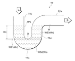
続いて、図3を参照しながらトラップ部TPについて説明する。図3は、トラップ部TPを示す概略図である。図3に示されるように、トラップ部TPは上流側から順に、上流接続部TPaと、上流封水部TPbと、底部TPcと、下流封水部TPdと、下流あふれ部TPeとを備えている。 Next, the trap unit TP will be described with reference to FIG. FIG. 3 is a schematic diagram showing the trap unit TP. As shown in FIG. 3, the trap part TP includes an upstream connection part TPa, an upstream sealing part TPb, a bottom part TPc, a downstream sealing part TPd, and a downstream overflow part Tpe in order from the upstream side. .
上流接続部TPaは、ボウル部201の排水口203に繋がる部分である。矢印Aの上流側に排水口203が繋がっており、ボウル部201から排水口203に流れ込んだ尿や洗浄水は矢印Aに沿って上流接続部TPaに流れ込む。
The upstream connection portion TPa is a portion connected to the
上流封水部TPb、底部TPc、及び下流封水部TPdは、水が溜まるようにU字状を成すように形成されている。上流接続部TPaから流れ込んだ水は、下流あふれ部TPeの下側内壁面であるウェアWよりも下側に溜まるように構成されている。封水深Wdは、ウェアWと、底部TPcの上側内壁面であるディップDとの間の鉛直方向の長さである。従って、上流封水部TPbに溜まる上流封水WS1と、下流封水部TPdに溜まる下流封水WS3とによって封水が形成されている。 The upstream sealing portion TPb, the bottom portion TPc, and the downstream sealing portion TPd are formed to have a U shape so that water can accumulate. The water that has flowed in from the upstream connection portion TPa is configured to accumulate below the wear W that is the lower inner wall surface of the downstream overflow portion Tpe. The sealed water depth Wd is the length in the vertical direction between the wear W and the dip D that is the upper inner wall surface of the bottom portion TPc. Accordingly, the sealed water is formed by the upstream sealed water WS1 accumulated in the upstream sealed water portion TPb and the downstream sealed water WS3 accumulated in the downstream sealed water portion TPd.
本明細書では、底部TPcに溜まる底溜水WS2と、上流封水WS1及び下流封水WS3とを合わせて、トラップ部TPの溜水Wsとしている。本実施形態において、溜水Wsの水量は、約100mLとなるように形成されており、0.5L程度の少水量でも洗浄が可能となっている。尚、節水型ではない通常のタイプのトラップでは、溜水量が約400〜600mLであり、洗浄水量は約1.4Lであるので、本実施形態のトラップ部TPは極めて節水性が向上したものとなっている。尚、本実施形態ではU字型のトラップをトラップ部TPとして採用したけれども、上述した機能を果たす限りその他の形態のトラップを採用することも好ましいものである。 In this specification, the bottom stored water WS2 accumulated in the bottom portion TPc, the upstream sealed water WS1 and the downstream sealed water WS3 are combined to form the stored water Ws of the trap portion TP. In the present embodiment, the amount of the stored water Ws is formed to be about 100 mL, and cleaning is possible even with a small amount of water of about 0.5 L. In addition, in a normal type trap that is not a water-saving type, the amount of stored water is about 400 to 600 mL, and the amount of washing water is about 1.4 L. Therefore, the trap portion TP of this embodiment has extremely improved water saving. It has become. In the present embodiment, a U-shaped trap is adopted as the trap portion TP. However, it is also preferable to adopt another form of trap as long as the above-described function is achieved.
続いて、図4を参照しながら、制御部102が出力する制御信号の具体例について説明する。図4は、人感センサー101及び制御部102の挙動を示すタイミングチャートである。図4の(A)は、人感センサー101から制御部102に出力される検知信号を示し、図4の(B)は、制御部102から電磁弁103に出力される制御信号を示している。
Next, a specific example of the control signal output by the
図4の(A)に示されているように、人感センサー101からは、時刻t1から時刻t2にかけて使用者が小便器本体20の前に立っていることを示す検知信号が出力されている。時刻t2を過ぎると検知信号が出力されなくなるので、制御部102は排尿が終わって使用者が立ち去ったと判断する。
As shown in FIG. 4A, the
図4の(B)に示されているように、制御部102は、時刻t3から時刻t4にかけて電磁弁103を全開するための制御信号「1」を出力する。制御部102は、時刻t4から時刻t5までは、電磁弁103を全開するための制御信号「1」を出力しない。制御部102は、時刻t5から時刻t6にかけて電磁弁103を全開するための制御信号「1」を再度出力する。
As shown in FIG. 4B, the
このような制御を行った場合、トラップ部TPやその下流の配管内がどのようになっているかについて、図5〜図9を参照しながら説明する。図5は、小便器USに排尿した場合の、トラップ部TPの様子を示す概略図である。図6は、小便器USに排尿した場合の、小便器USに繋がっている器具排水管50及び排水横枝管51の内部の様子を示す概略図である。図7は、図5に示す状況から洗浄水を流した場合の、トラップ部TPの様子を示す概略図である。図8は、図5に示す状況から洗浄水を流した場合の、器具排水管50及び排水横枝管51の内部の様子を示す概略図である。図9は、図8に示す状況から更に洗浄水を流した場合の、器具排水管50及び排水横枝管51の内部の様子を示す概略図である。
When such control is performed, it will be described with reference to FIGS. 5 to 9 how the trap portion TP and the piping in the downstream thereof are formed. FIG. 5 is a schematic diagram showing the state of the trap portion TP when urinating into the urinal US. FIG. 6 is a schematic view showing the inside of the
小便器USに排尿すると、ボウル部201のボウル壁面202に尿流が当たり、ボウル壁面202を伝って尿が排水口203から下流に流れる。図5の(A)に示されるように、排水口203に入った尿Urは矢印Aに沿ってトラップ部TPに流れ込む。続いて、図5の(B)に示されるように、尿Urの流入によって溜水Wsが下流あふれ部TPeへと押し流される。
When urination is performed in the urinal US, a urine flow strikes the
続いて、図5の(C)に示されるように、溜水Wsは完全に押し流されて、トラップ部TP内は尿Urによって満たされる。排尿が終了すると、図5の(D)に示されるように、上流封水部TPb、底部TPc、及び下流封水部TPdに尿Urが残存する。図5の(A)から(D)に示した状況は、図4の時刻t1から時刻t2に相当する。 Subsequently, as shown in FIG. 5C, the stored water Ws is completely washed away, and the trap portion TP is filled with urine Ur. When urination ends, as shown in FIG. 5D, urine Ur remains in the upstream sealing portion TPb, the bottom portion TPc, and the downstream sealing portion TPd. The situation shown in FIGS. 5A to 5D corresponds to the time t1 to the time t2 in FIG.
図5の(B)に示したように溜水Wsが矢印B方向に押し流されると、図6の(A)に示されるように、器具排水管50に流れ込む。器具排水管50は排水横枝管51に繋がっているので、溜水Wsは排水横枝管51に流れ込む。図5の(B)では、排尿によって流れ込む尿Urに押し出されて溜水Wsが下流側に流出しているので、その流れる速度は比較的緩やかなものであって、瞬間流量は少ないものである。従って、溜水Wsは排水横枝管51に流れ込んでも、ほとんどの部分が上流側Fに流れることはなく、下流側Eに流れていく。
As shown in FIG. 5B, when the stored water Ws is pushed away in the direction of arrow B, it flows into the
図6の(B)に示されるように、溜水Wsに続いて尿Urが流れ込んでも、やはりその流れる速度は比較的緩やかなものであって、瞬間流量は少ないものである。従って、尿Urは排水横枝管51に流れ込んでも、ほとんどの部分が上流側Fに流れることはなく、下流側Eに流れていく。
As shown in FIG. 6B, even if the urine Ur flows after the stored water Ws, the flowing speed is still relatively slow and the instantaneous flow rate is small. Therefore, even if the urine Ur flows into the drainage
続いて、図4の時刻t3から時刻t4に示すように、制御部102から電磁弁103を全開する制御信号「1」が出力されると、電磁弁103が全開され洗浄水がスプレッダー35からボウル部201のボウル壁面202に沿って流れる。ボウル壁面202を伝って洗浄水が排水口203から下流に流れる。図7の(A)に示されるように、排水口203に入った洗浄水Wfは矢印Aに沿ってトラップ部TPに流れ込む。続いて、図7の(B)に示されるように、洗浄水Wfの流入によって尿Urが下流あふれ部TPeへと押し流される。
Subsequently, as shown from time t3 to time t4 in FIG. 4, when the control signal “1” for fully opening the
続いて、図7の(C)に示されるように、尿Urは完全に押し流されて、トラップ部TP内は洗浄水Wfによって満たされる。最初の洗浄が終了すると、図7の(C)に示されるように、上流封水部TPb、底部TPc、及び下流封水部TPdに洗浄水Wfが溜水Wsとして残存する。図7の(A)から(C)に示した状況は、図4の時刻t3から時刻t4に相当する。 Subsequently, as shown in FIG. 7C, the urine Ur is completely washed away, and the trap portion TP is filled with the washing water Wf. When the first cleaning is completed, as shown in FIG. 7C, the cleaning water Wf remains as the stored water Ws in the upstream sealing portion TPb, the bottom portion TPc, and the downstream sealing portion TPd. The situation shown in FIGS. 7A to 7C corresponds to the time t3 to the time t4 in FIG.
図7の(B)に示したように尿Urが矢印B方向に押し流されると、図8の(A)に示されるように、器具排水管50に流れ込む。器具排水管50は排水横枝管51に繋がっているので、尿Urは排水横枝管51に流れ込む。図7の(B)では、洗浄水Wfに押し出されて尿Urが下流側に流出しているので、その流れる速度は比較的速いものであって、瞬間流量は多いものである。従って、尿Urは排水横枝管51に流れ込むと、上流側Fと下流側Eとに分かれる。
When the urine Ur is pushed away in the direction of arrow B as shown in FIG. 7B, it flows into the
更にトラップ部TPに洗浄水Wfが流入すると、その下流側である器具排水管50から排水横枝管51にも、洗浄水Wfが流れ込む。図8の(B)に示されるように、比較的瞬間流量の多い洗浄水Wfが流れ込むと、尿Urを上流側Fに逆流した尿Ur1と下流側Eに流れた尿Ur2とに分断する。
Further, when the cleaning water Wf flows into the trap portion TP, the cleaning water Wf flows from the
洗浄水Wfの供給が終了すると、図8の(C)に示されるように、洗浄水Wfは下流側Eに流れた尿Ur2と共に下流側Eへと流れていく。そのため、上流側Fに逆流した尿Ur1は洗浄水Wfに流されることなく取り残される。図8の(D)に示されるように、残留した尿Ur1は、徐々に下流側Eに流れていくものの、排水横枝管51の内側管壁に付着して残存する。
When the supply of the cleaning water Wf is completed, the cleaning water Wf flows to the downstream side E together with the urine Ur2 that flows to the downstream side E, as shown in FIG. Therefore, the urine Ur1 flowing back to the upstream side F is left without flowing into the washing water Wf. As shown in FIG. 8D, the remaining urine Ur1 gradually flows to the downstream side E, but remains attached to the inner tube wall of the drainage
続いて、図4の時刻t5から時刻t6に示すように、制御部102から電磁弁103を全開する制御信号「1」が再度出力されると、電磁弁103が全開され洗浄水がスプレッダー35からボウル部201のボウル壁面202に沿って流れる。ボウル壁面202を伝って洗浄水が排水口203から下流に流れる。排水口203に入った洗浄水Wfはトラップ部TPに流れ込む。トラップ部TPには尿Urが残存しないように置換が完了しているので(図7の(C)参照)、洗浄水Wfの流入によって洗浄水Wf(溜水Ws)が下流あふれ部TPeへと押し流される。
Subsequently, as shown from time t5 to time t6 in FIG. 4, when the control signal “1” for fully opening the
洗浄水Wfが矢印B方向に押し流されると、図9の(A)に示されるように、器具排水管50に流れ込む。器具排水管50は排水横枝管51に繋がっているので、洗浄水Wfは排水横枝管51に流れ込む。洗浄水Wfがそのまま下流側に流出しているので、その流れる速度は比較的速いものであって、瞬間流量は多いものである。従って、洗浄水Wfは排水横枝管51に流れ込むと、上流側Fと下流側Eとに分かれる。排水横枝管51に残存していた尿Urは徐々に下流に流れているため、洗浄水Wfが流入して上流側Fに向かった分は尿Urを覆うように逆流する。
When the washing water Wf is pushed away in the direction of arrow B, it flows into the
洗浄水Wfの供給が終了すると、図9の(B)に示されるように、洗浄水Wfは残存している尿Ur1と共に下流側Eへと流れていく。従って、図9の(C)に示されるように、残留した尿Ur1は洗浄水Wfと共に下流側に流れ去り、排水横枝管51の内側管壁に付着して残存していた尿Urが洗浄される。
When the supply of the cleaning water Wf is completed, the cleaning water Wf flows to the downstream side E together with the remaining urine Ur1, as shown in FIG. 9B. Accordingly, as shown in FIG. 9C, the remaining urine Ur1 flows downstream together with the washing water Wf, and the urine Ur remaining on the inner tube wall of the drainage
図9を参照しながら説明した残存尿Ur1の洗浄効果を更に高めるために、2回目に流す洗浄水の瞬間流量(電磁弁103近傍の管路を通過する際の瞬間流量(m3/s))を相対的に高めることも好ましい態様である。このように、2回目に流す洗浄水の瞬間流量を相対的に高める制御の例を図10を参照しながら説明する。図10は、人感センサー101及び制御部102の挙動であって、図4に示したものとは異なるパターンの挙動を示すタイミングチャートである。
In order to further enhance the cleaning effect of the residual urine Ur1 described with reference to FIG. 9, the instantaneous flow rate of the wash water to be flown for the second time (the instantaneous flow rate (m 3 / s when passing through the conduit near the electromagnetic valve 103) ) Is relatively preferable. As described above, an example of control for relatively increasing the instantaneous flow rate of the cleaning water to be flown for the second time will be described with reference to FIG. FIG. 10 is a timing chart showing the behavior of the
図10の(A)は、人感センサー101から制御部102に出力される検知信号を示し、図10の(B)は、制御部102から電磁弁103に出力される制御信号を示している。
10A shows a detection signal output from the
図10の(A)に示されているように、人感センサー101からは、時刻t1から時刻t2にかけて使用者が小便器本体20の前に立っていることを示す検知信号が出力されている。時刻t2を過ぎると検知信号が出力されなくなるので、制御部102は排尿が終わって使用者が立ち去ったと判断する。
As shown in FIG. 10A, the
図10の(B)に示されているように、制御部102は、時刻t3から時刻t4にかけて電磁弁103を全開に対して70%開くための制御信号「0.7」を出力する。制御部102は、時刻t4から時刻t5までは、電磁弁103を開くための制御信号を出力しない。制御部102は、時刻t5から時刻t6にかけて電磁弁103を全開するための制御信号「1」を出力する。
As shown in FIG. 10B, the
このような制御を行うと、時刻t3から時刻t4において電磁弁103が70%開くことによって供給される洗浄水Wfの瞬間流量(電磁弁103近傍の管路を通過する際の瞬間流量(m3/s))は相対的に低下するので、尿Urの上流側Fへの逆流は抑制される。そして、時刻t5から時刻t6において電磁弁103が全開することによって供給される洗浄水Wfの瞬間流量は相対的に上昇する。従って、図11に示されるように、上流側Fに逆流した尿Ur1よりも確実に多くの量の洗浄水Wfが上流側Fに逆流するので、確実に残存尿Ur1を洗い流すことができる。
When such control is performed, the instantaneous flow rate of the cleaning water Wf supplied by opening the
尚、図10に示す制御信号の例では、パルス振幅を異ならせることで互いに異なる制御信号であることを認識させる例を示したが、制御信号の例はこれに限られるものではない。例えば、パルス幅変調方式の制御を行うことも好ましい態様である。また例えば、電磁弁103の開度を示す異なる種類の制御信号を併用することも好ましい態様である。具体的には、時刻t3から時刻t4までは、電磁弁103の開度を全開に対して70%とする信号を第1チャネルを通じて出力し、時刻t5から時刻t6までは、電磁弁103の開度を全開にする信号を第2チャネルを通じて出力することも好ましいものである。
In the example of the control signal shown in FIG. 10, an example is shown in which different pulse amplitudes are used to recognize different control signals, but the example of the control signal is not limited to this. For example, it is also a preferable aspect to control the pulse width modulation method. For example, it is also a preferable aspect to use different types of control signals indicating the opening degree of the
上述したように本実施形態に係る小便器USは、トイレに設置され、器具排水管50によって排水横枝管51に接続される小便器である。小便器USは、(1)尿流を受けるボウル部201と、このボウル部201の底部に開口した排水口203と、この排水口203に連通し封水を形成するトラップ部TPと、を有する小便器本体20と、(2)ボウル部201に洗浄水Wfを供給するための給水手段としての給水管30,31と、(3)給水管30,31からボウル部201への給水を調整する調整手段としての電磁弁103と、(4)電磁弁103を制御することで、給水管30,31からボウル部201への給水を実行させる制御手段としての制御部102と、を備える。
As described above, the urinal US according to the present embodiment is a urinal that is installed in a toilet and connected to the drainage
制御部102は、少なくともトラップ部TPに溜まっている尿Urを洗浄水Wfによって置換することが可能な第一洗浄モード(図4及び図10における時刻t3から時刻t4の制御モード、以下同じ)を実行し、第一洗浄モードを実行した後、所定時間給水を停止し(図4及び図10における時刻t4から時刻t5)、第一洗浄モードにおける洗浄水の供給によって置換された尿Urを含む排水の少なくとも一部が、器具排水管50が排水横枝管51に合流する接続部よりも下流側に流れた後に、給水を再開する第二洗浄モード(図4及び図10における時刻t4から時刻t6の制御モード、以下同じ)を実行する。
The
本実施形態に係る小便器USでは、制御部102が、少なくともトラップ部TPに溜まっている尿Urを洗浄水Wfによって置換することが可能な第一洗浄モードを先に実行する。この第一洗浄モードの実行によって、尿Urの置換に適した給水が電磁弁103によってなされ、ボウル部201を流れた後にトラップ部TPに流れ込み尿Urを置換することが可能となる。第一洗浄モードによる給水は第二洗浄モードによる給水に先立って行われるものであるから、トラップ部TPに溜まっている尿Urの置換に適合する給水を先に行うことができる。
In the urinal US according to the present embodiment, the
更に本実施形態に係る小便器USでは、制御部102が、第一洗浄モードの実行後に、第二洗浄モードを実行する。第一洗浄モードの実行によって、トラップ部TPに溜まっている尿Urの置換に適合する給水を行うので、尿Urの濃度が高い液体が排水として器具排水管50から排水横枝管51に流れ込む。排水横枝管51に流れ込んだ排水は、流れ込む瞬間流量が多ければ排水横枝管51の上流側Fに逆流し、その瞬間流量がさほど多くなければ排水横枝管51の下流側Eにそのまま流れていく。そこで、第二洗浄モードでは、第一洗浄モードを実行した後、所定時間給水を停止するものとしている。このように所定時間給水を停止することで、排水横枝管51に流れ込んだ排水が本実施形態のように上流側Fに逆流したとしても、下流側Eに流れてくるのを待つことができる。更に第二洗浄モードでは、所定時間給水を停止することで、第一洗浄モードにおける洗浄水Wfの供給によって置換された尿Urを含む排水が接続部よりも下流側Eに流れた後に、給水を再開する。第一洗浄モードの実行によって、トラップ部TPにおける尿Urは既に置換が完了されているか、排水横枝管51の上流側Fに逆流したとしても高い尿濃度の液体が残存しない程度に置換されている。従って、第二洗浄モードによる給水をどのように設定したとしても、既に下流側Eに流れた排水を洗い流すように作用するので、尿Urが高濃度で残存することによる尿石発生のおそれを確実に低減することができる。
Further, in the urinal US according to the present embodiment, the
このように、トラップ部TPに溜まっている尿Urを洗浄水Wfによって置換することが可能な第一洗浄モードを実行した後、所定時間の給水停止を含む第二洗浄モードを実行することで、節水性能は確保しつつも、排水横枝管51内における尿石の発生を抑制することが可能な小便器USを提供することができる。
Thus, after executing the first cleaning mode in which the urine Ur accumulated in the trap part TP can be replaced by the cleaning water Wf, by executing the second cleaning mode including the water supply stop for a predetermined time, It is possible to provide a urinal US that can suppress the generation of urinary stones in the drainage
また本実施形態に係る小便器USでは、制御部は、第二洗浄モードにおける給水の再開を、第一洗浄モードにおける洗浄水Wfの供給によって置換された尿Urを含む排水が、器具排水管50が排水横枝管51に合流する接続部よりも下流側に流れ去るタイミングに対応させることも好ましい。
Further, in the urinal US according to the present embodiment, the control unit restarts the water supply in the second cleaning mode, and the drainage containing the urine Ur replaced by the supply of the cleaning water Wf in the first cleaning mode is the
この好ましい態様では、第二洗浄モードにおける給水の再開を、第一洗浄モードにおける排水が接続部よりも下流側に流れ去るタイミングに対応させることで、第一洗浄モードにおける排水が接続部よりも上流側には無い状態で給水を再開することが可能となる。従って、第二洗浄モードによる給水をどのように設定したとしても、既に下流側に流れた排水を洗い流すように作用するので、尿Urが高濃度で残存することによる尿石発生のおそれを確実に低減することができる。 In this preferred embodiment, the resumption of water supply in the second cleaning mode corresponds to the timing at which the waste water in the first cleaning mode flows downstream from the connection portion, so that the waste water in the first cleaning mode is upstream from the connection portion. It becomes possible to resume water supply without being on the side. Therefore, no matter how the water supply in the second washing mode is set, it acts to wash away the waste water that has already flowed downstream, so that the possibility of urine stones due to the high concentration of urine Ur remains is ensured. Can be reduced.
また本実施形態に係る小便器USでは、制御部102は、第一洗浄モードにおける総給水量(L)が、トラップ部TPの溜水Wsの水量(L)を超えるように電磁弁103を制御している。
In the urinal US according to the present embodiment, the
このように、第一洗浄モードにおける総給水量が、トラップ部の溜水Wsの水量を超えるように給水するので、トラップ部TPにおける尿Urを置換するか、排水横枝管51の上流側に逆流したとしても高い尿濃度の液体が残存しない程度に置換することが確実に可能となる。従って、第二洗浄モードにおける給水では、確実に尿濃度が下がったトラップ部TPに洗浄水を供給しながら排水を行うので、第二洗浄モードの初期段階から尿濃度が確実に下がった排水が接続部から排水横枝管51に流れ込むことになる。結果として、尿石の発生を抑制しつつも第二洗浄モードにおける水量を過剰に増やす必要がなく、より節水に資することができる。
Thus, since the total water supply amount in the first cleaning mode is supplied so as to exceed the water amount of the trapped water Ws of the trap portion, the urine Ur in the trap portion TP is replaced or the upstream side of the drainage
また本実施形態に係る小便器USでは、制御部102は、第一洗浄モードにおける総給水量(L)が、第二洗浄モードにおける総給水量(L)を超えるように電磁弁103を制御している。
Further, in the urinal US according to the present embodiment, the
このように、第一洗浄モードにおける総給水量(L)が、第二洗浄モードにおける総給水量(L)を超えるように電磁弁103を制御するので、第一洗浄モードにおいてトラップ部TP内の尿Urが含まれた溜水を置換するのにより多くの洗浄水Wfを供給することができる。一方で、第二洗浄モードにおける総給水量を抑制することができるので、第一洗浄モードから第二洗浄モードを通した全体の給水量を過剰に増やすことなく、置換率を高めると共に排水横枝管51内における尿Urの高濃度で残留することを抑制することができる。
As described above, the
また本実施形態に係る小便器USでは、制御部102は、第一洗浄モードにおいてトラップ部TPから下流側に排出される瞬間排水量(下流側に排出される排水の瞬間流量)よりも、第二洗浄モードにおいてトラップ部TPから下流側に排出される瞬間排水量が上回るように電磁弁103を制御している(図10参照)。
Moreover, in the urinal US which concerns on this embodiment, the
このように、第一洗浄モードにおける瞬間排水量よりも第二洗浄モードにおける瞬間排水量が上回るので、第一洗浄モードの排水が接続部から上流側Fに逆流するよりも更に上流側Fに第二洗浄モードの排水が逆流する(図11参照)。従って、器具排水管50が排水横枝管51に合流する接続部より上流側Fにおいても、確実に尿を含む排水を下流側Eに流すことができる。
As described above, since the instantaneous drainage amount in the second cleaning mode is greater than the instantaneous drainage amount in the first cleaning mode, the second cleaning is further performed on the upstream side F than the drainage in the first cleaning mode flows backward from the connecting portion to the upstream side F. The mode drainage flows backward (see FIG. 11). Therefore, the waste water containing urine can be surely flowed to the downstream side E also on the upstream side F from the connection portion where the
また本実施形態に係る小便器USでは、制御部102は、第一洗浄モードにおけるボウル部201への瞬間給水量(給水の瞬間流量)よりも、第二洗浄モードにおけるボウル部201への瞬間給水量が上回るように電磁弁103を制御している(図10参照)。
Moreover, in the urinal US which concerns on this embodiment, the
このように、第一洗浄モードにおける瞬間給水量よりも第二洗浄モードにおける瞬間給水量を上回らせることで、確実に第一洗浄モードにおける瞬間排水量よりも第二洗浄モードにおける瞬間排水量を上回らせることができる。従って、ボウル部201への瞬間給水量を異ならせるという簡単な構成で、器具排水管50が排水横枝管51に合流する接続部より上流側Fにおいても、確実に尿を含む排水を下流側Eに流すことができる。
Thus, by making the instantaneous water supply amount in the second cleaning mode exceed the instantaneous water supply amount in the first cleaning mode, it is possible to reliably exceed the instantaneous drainage amount in the second cleaning mode than in the first cleaning mode. Can do. Therefore, with a simple configuration in which the instantaneous water supply amount to the
以上、具体例を参照しつつ本発明の実施の形態について説明した。しかし、本発明はこれらの具体例に限定されるものではない。すなわち、これら具体例に、当業者が適宜設計変更を加えたものも、本発明の特徴を備えている限り、本発明の範囲に包含される。例えば、前述した各具体例が備える各要素およびその配置、材料、条件、形状、サイズなどは、例示したものに限定されるわけではなく適宜変更することができる。また、前述した各実施の形態が備える各要素は、技術的に可能な限りにおいて組み合わせることができ、これらを組み合わせたものも本発明の特徴を含む限り本発明の範囲に包含される。 The embodiments of the present invention have been described above with reference to specific examples. However, the present invention is not limited to these specific examples. In other words, those specific examples that have been appropriately modified by those skilled in the art are also included in the scope of the present invention as long as they have the characteristics of the present invention. For example, the elements included in each of the specific examples described above and their arrangement, materials, conditions, shapes, sizes, and the like are not limited to those illustrated, but can be changed as appropriate. Moreover, each element with which each embodiment mentioned above is provided can be combined as long as technically possible, and the combination of these is also included in the scope of the present invention as long as it includes the features of the present invention.
US:小便器
WL:壁面
10:給水ユニット
101:人感センサー
102:制御部
103:電磁弁
20:小便器本体
201:ボウル部
202:ボウル壁面
203:排水口
204:目皿
30:給水管
31:給水管
35:スプレッダー
40:建築側給水管
50:器具排水管
51:排水横枝管
TP:トラップ部
TPa:上流接続部
TPb:上流封水部
TPc:底部
TPd:下流封水部
TPe:下流あふれ部
W:ウェア
D:ディップ
Wd:封水深
WS1:上流封水
WS2:底溜水
WS3:下流封水
Ur:尿
Ws:溜水
Wf:洗浄水
US: Urinal WL: Wall surface 10: Water supply unit 101: Human sensor 102: Control unit 103: Solenoid valve 20: Urinal body 201: Bowl portion 202: Bowl wall surface 203: Drain outlet 204: Eye plate 30: Water supply pipe 31 : Water supply pipe 35: Spreader 40: Building side water supply pipe 50: Appliance drain pipe 51: Drainage side branch pipe TP: Trap part TPa: Upstream connection part TPb: Upstream seal part TPc: Bottom part TPd: Downstream seal part Tpe: Downstream Overflow W: Wear D: Dip Wd: Sealed Depth WS1: Upstream Sealed Water WS2: Bottom Reserved Water WS3: Downstream Sealed Water Ur: Urine Ws: Retained Water Wf: Wash Water
Claims (4)
尿流を受けるボウル部と、このボウル部の底部に開口した排水口と、この排水口から流入する尿及び洗浄水を溜めるとともに排水として前記器具排水管に排出するトラップ部と、を有する小便器本体と、
前記ボウル部に洗浄水を供給するための給水手段と、
前記給水手段から前記ボウル部への洗浄水の供給を調整する調整手段と、
前記調整手段を制御することで、前記給水手段から前記ボウル部へ洗浄水を供給させる制御手段と、を備え、
前記制御手段は、
第一洗浄モードと第二洗浄モードとを実行するものであって、
総給水量が前記トラップ部の溜水量を超えるように前記調整手段を制御して洗浄水を供給する前記第一洗浄モードを実行した後、所定時間洗浄水の供給を停止し、前記第一洗浄モードにおける洗浄水の供給によって前記トラップ部から前記器具排水管に排出された排水の少なくとも一部が、前記器具排水管が前記排水横枝管に接続される接続部よりも下流側に流れ去った後に、洗浄水の供給を再開する前記第二洗浄モードを実行することを特徴とする小便器。 A urinal installed in a toilet and connected in the middle of a drainage side branch pipe extending laterally by an instrument drainage pipe,
A urinal having a bowl part for receiving a urine flow, a drain opening opened at the bottom of the bowl part, and a trap part for collecting urine and washing water flowing from the drain outlet and discharging the urine as drainage to the instrument drain pipe The body,
Water supply means for supplying cleaning water to the bowl part;
Adjusting means for adjusting the supply of cleaning water from the water supply means to the bowl portion;
Control means for supplying cleaning water from the water supply means to the bowl portion by controlling the adjustment means,
The control means includes
The first cleaning mode and the second cleaning mode are executed,
After executing the first cleaning mode in which the adjustment means is controlled to supply the cleaning water so that the total water supply amount exceeds the amount of water stored in the trap portion, the supply of the cleaning water is stopped for a predetermined time, and the first cleaning is performed. At least a part of the drainage discharged from the trap portion to the appliance drain pipe by the supply of cleaning water in the mode has flowed downstream from the connection portion where the appliance drain pipe is connected to the drain side branch pipe . The urinal characterized in that the second washing mode for restarting the supply of the washing water is executed later.
Priority Applications (1)
| Application Number | Priority Date | Filing Date | Title |
|---|---|---|---|
| JP2014004481A JP5692422B2 (en) | 2014-01-14 | 2014-01-14 | urinal |
Applications Claiming Priority (1)
| Application Number | Priority Date | Filing Date | Title |
|---|---|---|---|
| JP2014004481A JP5692422B2 (en) | 2014-01-14 | 2014-01-14 | urinal |
Related Parent Applications (1)
| Application Number | Title | Priority Date | Filing Date |
|---|---|---|---|
| JP2010128034A Division JP5455064B2 (en) | 2010-06-03 | 2010-06-03 | urinal |
Publications (3)
| Publication Number | Publication Date |
|---|---|
| JP2014062459A JP2014062459A (en) | 2014-04-10 |
| JP2014062459A5 JP2014062459A5 (en) | 2014-08-07 |
| JP5692422B2 true JP5692422B2 (en) | 2015-04-01 |
Family
ID=50617909
Family Applications (1)
| Application Number | Title | Priority Date | Filing Date |
|---|---|---|---|
| JP2014004481A Active JP5692422B2 (en) | 2014-01-14 | 2014-01-14 | urinal |
Country Status (1)
| Country | Link |
|---|---|
| JP (1) | JP5692422B2 (en) |
Families Citing this family (2)
| Publication number | Priority date | Publication date | Assignee | Title |
|---|---|---|---|---|
| JP6540937B2 (en) * | 2014-09-18 | 2019-07-10 | Toto株式会社 | urinal |
| JP7011217B2 (en) * | 2017-09-29 | 2022-01-26 | Toto株式会社 | urinal |
Family Cites Families (5)
| Publication number | Priority date | Publication date | Assignee | Title |
|---|---|---|---|---|
| JPS56156341A (en) * | 1980-05-02 | 1981-12-03 | Japan National Railway | Connecting type urinal and installing thereof |
| JPS6322931A (en) * | 1986-07-16 | 1988-01-30 | 株式会社イナックス | Method and apparatus for washing urinal |
| JPH07102621A (en) * | 1993-09-30 | 1995-04-18 | Matsushita Electric Works Ltd | Automatic flushing device of urinal |
| JP4088976B2 (en) * | 2004-05-26 | 2008-05-21 | Toto株式会社 | Automatic cleaning device |
| JP2007321372A (en) * | 2006-05-30 | 2007-12-13 | Toto Ltd | Toilet bowl washing device |
-
2014
- 2014-01-14 JP JP2014004481A patent/JP5692422B2/en active Active
Also Published As
| Publication number | Publication date |
|---|---|
| JP2014062459A (en) | 2014-04-10 |
Similar Documents
| Publication | Publication Date | Title |
|---|---|---|
| JP5633198B2 (en) | urinal | |
| JP5455064B2 (en) | urinal | |
| JP2012149415A (en) | Urinal | |
| US9624657B2 (en) | Urinal | |
| US20150275495A1 (en) | Urinal | |
| JP5692422B2 (en) | urinal | |
| JP5712822B2 (en) | Urinal equipment | |
| JP2012136915A (en) | Water supply equipment | |
| JP5892454B2 (en) | urinal | |
| JP2017048673A (en) | Flush toilet bowl | |
| JP2017048674A (en) | Flush toilet bowl | |
| JP5724690B2 (en) | Urinal equipment | |
| JP6865923B2 (en) | Flush toilet | |
| JP5716946B2 (en) | urinal | |
| JP6049196B2 (en) | urinal | |
| JP5716947B2 (en) | urinal | |
| JP7037719B2 (en) | urinal | |
| JP6838700B2 (en) | Toilet bowl system | |
| JP6932333B2 (en) | urinal | |
| JP7435030B2 (en) | urinal | |
| JP2018096167A (en) | Toilet bowl device | |
| JP7013949B2 (en) | urinal | |
| JP5128884B2 (en) | Urinal washing system | |
| WO2011152401A1 (en) | Urinal device | |
| JP2022026099A (en) | urinal |
Legal Events
| Date | Code | Title | Description |
|---|---|---|---|
| A621 | Written request for application examination |
Free format text: JAPANESE INTERMEDIATE CODE: A621 Effective date: 20140212 |
|
| A521 | Written amendment |
Free format text: JAPANESE INTERMEDIATE CODE: A523 Effective date: 20140623 |
|
| A871 | Explanation of circumstances concerning accelerated examination |
Free format text: JAPANESE INTERMEDIATE CODE: A871 Effective date: 20140623 |
|
| A975 | Report on accelerated examination |
Free format text: JAPANESE INTERMEDIATE CODE: A971005 Effective date: 20140805 |
|
| A131 | Notification of reasons for refusal |
Free format text: JAPANESE INTERMEDIATE CODE: A131 Effective date: 20140813 |
|
| A521 | Written amendment |
Free format text: JAPANESE INTERMEDIATE CODE: A523 Effective date: 20141003 |
|
| A131 | Notification of reasons for refusal |
Free format text: JAPANESE INTERMEDIATE CODE: A131 Effective date: 20141112 |
|
| A521 | Written amendment |
Free format text: JAPANESE INTERMEDIATE CODE: A523 Effective date: 20141209 |
|
| TRDD | Decision of grant or rejection written | ||
| A01 | Written decision to grant a patent or to grant a registration (utility model) |
Free format text: JAPANESE INTERMEDIATE CODE: A01 Effective date: 20150106 |
|
| A61 | First payment of annual fees (during grant procedure) |
Free format text: JAPANESE INTERMEDIATE CODE: A61 Effective date: 20150119 |
|
| R150 | Certificate of patent or registration of utility model |
Ref document number: 5692422 Country of ref document: JP Free format text: JAPANESE INTERMEDIATE CODE: R150 |