JP5682008B2 - Booster and brake device using the same - Google Patents
Booster and brake device using the same Download PDFInfo
- Publication number
- JP5682008B2 JP5682008B2 JP2011023869A JP2011023869A JP5682008B2 JP 5682008 B2 JP5682008 B2 JP 5682008B2 JP 2011023869 A JP2011023869 A JP 2011023869A JP 2011023869 A JP2011023869 A JP 2011023869A JP 5682008 B2 JP5682008 B2 JP 5682008B2
- Authority
- JP
- Japan
- Prior art keywords
- reaction force
- master cylinder
- hydraulic pressure
- plunger
- regenerative
- Prior art date
- Legal status (The legal status is an assumption and is not a legal conclusion. Google has not performed a legal analysis and makes no representation as to the accuracy of the status listed.)
- Active
Links
- 238000006243 chemical reaction Methods 0.000 claims description 172
- 230000001172 regenerating effect Effects 0.000 claims description 84
- 239000012530 fluid Substances 0.000 claims description 18
- 230000005540 biological transmission Effects 0.000 description 16
- 230000008929 regeneration Effects 0.000 description 10
- 238000011069 regeneration method Methods 0.000 description 10
- 230000033001 locomotion Effects 0.000 description 9
- 230000002093 peripheral effect Effects 0.000 description 8
- 230000000994 depressogenic effect Effects 0.000 description 7
- 239000000428 dust Substances 0.000 description 7
- 230000000694 effects Effects 0.000 description 4
- 230000006835 compression Effects 0.000 description 3
- 238000007906 compression Methods 0.000 description 3
- 238000006073 displacement reaction Methods 0.000 description 2
- 229910000831 Steel Inorganic materials 0.000 description 1
- 230000001133 acceleration Effects 0.000 description 1
- 230000006837 decompression Effects 0.000 description 1
- 230000003247 decreasing effect Effects 0.000 description 1
- 238000010586 diagram Methods 0.000 description 1
- 238000007599 discharging Methods 0.000 description 1
- 230000014759 maintenance of location Effects 0.000 description 1
- 230000000149 penetrating effect Effects 0.000 description 1
- 239000011347 resin Substances 0.000 description 1
- 229920005989 resin Polymers 0.000 description 1
- 230000006641 stabilisation Effects 0.000 description 1
- 238000011105 stabilization Methods 0.000 description 1
- 239000010959 steel Substances 0.000 description 1
- 238000011144 upstream manufacturing Methods 0.000 description 1
Images


Classifications
-
- B—PERFORMING OPERATIONS; TRANSPORTING
- B60—VEHICLES IN GENERAL
- B60T—VEHICLE BRAKE CONTROL SYSTEMS OR PARTS THEREOF; BRAKE CONTROL SYSTEMS OR PARTS THEREOF, IN GENERAL; ARRANGEMENT OF BRAKING ELEMENTS ON VEHICLES IN GENERAL; PORTABLE DEVICES FOR PREVENTING UNWANTED MOVEMENT OF VEHICLES; VEHICLE MODIFICATIONS TO FACILITATE COOLING OF BRAKES
- B60T8/00—Arrangements for adjusting wheel-braking force to meet varying vehicular or ground-surface conditions, e.g. limiting or varying distribution of braking force
- B60T8/32—Arrangements for adjusting wheel-braking force to meet varying vehicular or ground-surface conditions, e.g. limiting or varying distribution of braking force responsive to a speed condition, e.g. acceleration or deceleration
- B60T8/34—Arrangements for adjusting wheel-braking force to meet varying vehicular or ground-surface conditions, e.g. limiting or varying distribution of braking force responsive to a speed condition, e.g. acceleration or deceleration having a fluid pressure regulator responsive to a speed condition
- B60T8/38—Arrangements for adjusting wheel-braking force to meet varying vehicular or ground-surface conditions, e.g. limiting or varying distribution of braking force responsive to a speed condition, e.g. acceleration or deceleration having a fluid pressure regulator responsive to a speed condition including valve means of the relay or driver controlled type
-
- B—PERFORMING OPERATIONS; TRANSPORTING
- B60—VEHICLES IN GENERAL
- B60T—VEHICLE BRAKE CONTROL SYSTEMS OR PARTS THEREOF; BRAKE CONTROL SYSTEMS OR PARTS THEREOF, IN GENERAL; ARRANGEMENT OF BRAKING ELEMENTS ON VEHICLES IN GENERAL; PORTABLE DEVICES FOR PREVENTING UNWANTED MOVEMENT OF VEHICLES; VEHICLE MODIFICATIONS TO FACILITATE COOLING OF BRAKES
- B60T1/00—Arrangements of braking elements, i.e. of those parts where braking effect occurs specially for vehicles
- B60T1/02—Arrangements of braking elements, i.e. of those parts where braking effect occurs specially for vehicles acting by retarding wheels
- B60T1/10—Arrangements of braking elements, i.e. of those parts where braking effect occurs specially for vehicles acting by retarding wheels by utilising wheel movement for accumulating energy, e.g. driving air compressors
-
- B—PERFORMING OPERATIONS; TRANSPORTING
- B60—VEHICLES IN GENERAL
- B60T—VEHICLE BRAKE CONTROL SYSTEMS OR PARTS THEREOF; BRAKE CONTROL SYSTEMS OR PARTS THEREOF, IN GENERAL; ARRANGEMENT OF BRAKING ELEMENTS ON VEHICLES IN GENERAL; PORTABLE DEVICES FOR PREVENTING UNWANTED MOVEMENT OF VEHICLES; VEHICLE MODIFICATIONS TO FACILITATE COOLING OF BRAKES
- B60T11/00—Transmitting braking action from initiating means to ultimate brake actuator without power assistance or drive or where such assistance or drive is irrelevant
- B60T11/10—Transmitting braking action from initiating means to ultimate brake actuator without power assistance or drive or where such assistance or drive is irrelevant transmitting by fluid means, e.g. hydraulic
- B60T11/16—Master control, e.g. master cylinders
- B60T11/18—Connection thereof to initiating means
-
- B—PERFORMING OPERATIONS; TRANSPORTING
- B60—VEHICLES IN GENERAL
- B60T—VEHICLE BRAKE CONTROL SYSTEMS OR PARTS THEREOF; BRAKE CONTROL SYSTEMS OR PARTS THEREOF, IN GENERAL; ARRANGEMENT OF BRAKING ELEMENTS ON VEHICLES IN GENERAL; PORTABLE DEVICES FOR PREVENTING UNWANTED MOVEMENT OF VEHICLES; VEHICLE MODIFICATIONS TO FACILITATE COOLING OF BRAKES
- B60T13/00—Transmitting braking action from initiating means to ultimate brake actuator with power assistance or drive; Brake systems incorporating such transmitting means, e.g. air-pressure brake systems
- B60T13/10—Transmitting braking action from initiating means to ultimate brake actuator with power assistance or drive; Brake systems incorporating such transmitting means, e.g. air-pressure brake systems with fluid assistance, drive, or release
- B60T13/24—Transmitting braking action from initiating means to ultimate brake actuator with power assistance or drive; Brake systems incorporating such transmitting means, e.g. air-pressure brake systems with fluid assistance, drive, or release the fluid being gaseous
- B60T13/46—Vacuum systems
- B60T13/52—Vacuum systems indirect, i.e. vacuum booster units
- B60T13/573—Vacuum systems indirect, i.e. vacuum booster units characterised by reaction devices
-
- B—PERFORMING OPERATIONS; TRANSPORTING
- B60—VEHICLES IN GENERAL
- B60T—VEHICLE BRAKE CONTROL SYSTEMS OR PARTS THEREOF; BRAKE CONTROL SYSTEMS OR PARTS THEREOF, IN GENERAL; ARRANGEMENT OF BRAKING ELEMENTS ON VEHICLES IN GENERAL; PORTABLE DEVICES FOR PREVENTING UNWANTED MOVEMENT OF VEHICLES; VEHICLE MODIFICATIONS TO FACILITATE COOLING OF BRAKES
- B60T13/00—Transmitting braking action from initiating means to ultimate brake actuator with power assistance or drive; Brake systems incorporating such transmitting means, e.g. air-pressure brake systems
- B60T13/10—Transmitting braking action from initiating means to ultimate brake actuator with power assistance or drive; Brake systems incorporating such transmitting means, e.g. air-pressure brake systems with fluid assistance, drive, or release
- B60T13/58—Combined or convertible systems
- B60T13/585—Combined or convertible systems comprising friction brakes and retarders
- B60T13/586—Combined or convertible systems comprising friction brakes and retarders the retarders being of the electric type
-
- B—PERFORMING OPERATIONS; TRANSPORTING
- B60—VEHICLES IN GENERAL
- B60T—VEHICLE BRAKE CONTROL SYSTEMS OR PARTS THEREOF; BRAKE CONTROL SYSTEMS OR PARTS THEREOF, IN GENERAL; ARRANGEMENT OF BRAKING ELEMENTS ON VEHICLES IN GENERAL; PORTABLE DEVICES FOR PREVENTING UNWANTED MOVEMENT OF VEHICLES; VEHICLE MODIFICATIONS TO FACILITATE COOLING OF BRAKES
- B60T13/00—Transmitting braking action from initiating means to ultimate brake actuator with power assistance or drive; Brake systems incorporating such transmitting means, e.g. air-pressure brake systems
- B60T13/74—Transmitting braking action from initiating means to ultimate brake actuator with power assistance or drive; Brake systems incorporating such transmitting means, e.g. air-pressure brake systems with electrical assistance or drive
-
- B—PERFORMING OPERATIONS; TRANSPORTING
- B60—VEHICLES IN GENERAL
- B60T—VEHICLE BRAKE CONTROL SYSTEMS OR PARTS THEREOF; BRAKE CONTROL SYSTEMS OR PARTS THEREOF, IN GENERAL; ARRANGEMENT OF BRAKING ELEMENTS ON VEHICLES IN GENERAL; PORTABLE DEVICES FOR PREVENTING UNWANTED MOVEMENT OF VEHICLES; VEHICLE MODIFICATIONS TO FACILITATE COOLING OF BRAKES
- B60T7/00—Brake-action initiating means
- B60T7/02—Brake-action initiating means for personal initiation
- B60T7/04—Brake-action initiating means for personal initiation foot actuated
- B60T7/042—Brake-action initiating means for personal initiation foot actuated by electrical means, e.g. using travel or force sensors
-
- B—PERFORMING OPERATIONS; TRANSPORTING
- B60—VEHICLES IN GENERAL
- B60T—VEHICLE BRAKE CONTROL SYSTEMS OR PARTS THEREOF; BRAKE CONTROL SYSTEMS OR PARTS THEREOF, IN GENERAL; ARRANGEMENT OF BRAKING ELEMENTS ON VEHICLES IN GENERAL; PORTABLE DEVICES FOR PREVENTING UNWANTED MOVEMENT OF VEHICLES; VEHICLE MODIFICATIONS TO FACILITATE COOLING OF BRAKES
- B60T8/00—Arrangements for adjusting wheel-braking force to meet varying vehicular or ground-surface conditions, e.g. limiting or varying distribution of braking force
- B60T8/32—Arrangements for adjusting wheel-braking force to meet varying vehicular or ground-surface conditions, e.g. limiting or varying distribution of braking force responsive to a speed condition, e.g. acceleration or deceleration
- B60T8/34—Arrangements for adjusting wheel-braking force to meet varying vehicular or ground-surface conditions, e.g. limiting or varying distribution of braking force responsive to a speed condition, e.g. acceleration or deceleration having a fluid pressure regulator responsive to a speed condition
- B60T8/48—Arrangements for adjusting wheel-braking force to meet varying vehicular or ground-surface conditions, e.g. limiting or varying distribution of braking force responsive to a speed condition, e.g. acceleration or deceleration having a fluid pressure regulator responsive to a speed condition connecting the brake actuator to an alternative or additional source of fluid pressure, e.g. traction control systems
- B60T8/4809—Traction control, stability control, using both the wheel brakes and other automatic braking systems
- B60T8/4827—Traction control, stability control, using both the wheel brakes and other automatic braking systems in hydraulic brake systems
- B60T8/4863—Traction control, stability control, using both the wheel brakes and other automatic braking systems in hydraulic brake systems closed systems
- B60T8/4872—Traction control, stability control, using both the wheel brakes and other automatic braking systems in hydraulic brake systems closed systems pump-back systems
-
- B—PERFORMING OPERATIONS; TRANSPORTING
- B60—VEHICLES IN GENERAL
- B60T—VEHICLE BRAKE CONTROL SYSTEMS OR PARTS THEREOF; BRAKE CONTROL SYSTEMS OR PARTS THEREOF, IN GENERAL; ARRANGEMENT OF BRAKING ELEMENTS ON VEHICLES IN GENERAL; PORTABLE DEVICES FOR PREVENTING UNWANTED MOVEMENT OF VEHICLES; VEHICLE MODIFICATIONS TO FACILITATE COOLING OF BRAKES
- B60T2270/00—Further aspects of brake control systems not otherwise provided for
- B60T2270/60—Regenerative braking
- B60T2270/604—Merging friction therewith; Adjusting their repartition
-
- B—PERFORMING OPERATIONS; TRANSPORTING
- B60—VEHICLES IN GENERAL
- B60W—CONJOINT CONTROL OF VEHICLE SUB-UNITS OF DIFFERENT TYPE OR DIFFERENT FUNCTION; CONTROL SYSTEMS SPECIALLY ADAPTED FOR HYBRID VEHICLES; ROAD VEHICLE DRIVE CONTROL SYSTEMS FOR PURPOSES NOT RELATED TO THE CONTROL OF A PARTICULAR SUB-UNIT
- B60W30/00—Purposes of road vehicle drive control systems not related to the control of a particular sub-unit, e.g. of systems using conjoint control of vehicle sub-units
- B60W30/18—Propelling the vehicle
- B60W30/18009—Propelling the vehicle related to particular drive situations
- B60W30/18109—Braking
- B60W30/18127—Regenerative braking
Landscapes
- Engineering & Computer Science (AREA)
- Transportation (AREA)
- Mechanical Engineering (AREA)
- Physics & Mathematics (AREA)
- Fluid Mechanics (AREA)
- Chemical & Material Sciences (AREA)
- Combustion & Propulsion (AREA)
- Regulating Braking Force (AREA)
- Braking Systems And Boosters (AREA)
Description
本発明は、アクチュエータによってブレーキ操作力を倍力する倍力装置及びこれを用いたブレーキ装置に関するものである。 The present invention relates to a booster that boosts a brake operating force by an actuator and a brake device using the same.
車両のブレーキ装置において、液圧式ブレーキによる摩擦制動とモータジェネレータ等の発電機による回生制動との制動力配分を制御して所望の制動力を得る回生協調制御が知られている。特許文献1には、マスタシリンダと各車輪の液圧ブレーキとの間に、ポンプ、アキュムレータ及び電磁弁等からなり液圧ブレーキに供給する液圧を増減及び保持する液圧制御装置を介装し、この液圧制御装置によって回生制動時に液圧ブレーキに供給する液圧を調整することにより回生協調制御を行なうブレーキ制御装置が記載されている。
2. Description of the Related Art Regenerative cooperative control is known that obtains a desired braking force by controlling a braking force distribution between friction braking by a hydraulic brake and regenerative braking by a generator such as a motor generator in a vehicle brake device. In
しかしながら、特許文献1に記載されたもののように液圧制御装置により回生協調制御を行なうブレーキ制御装置では、次のような問題がある。回生協調制御の実行中に、液圧制御装置によりブレーキ液圧を増減する際、マスタシリンダの液圧が変動するため、ブレーキペダルに対する反力が変動して、ブレーキペダルの操作フィーリングが悪化する。
However, a brake control device that performs regenerative cooperative control using a hydraulic control device, such as that described in
本発明は、回生協調時にブレーキペダルの反力の変動を低減してブレーキペダルの操作フィーリングを改善するようにした倍力装置及びこれを用いたブレーキ装置を提供することを目的とする。 SUMMARY OF THE INVENTION An object of the present invention is to provide a booster that reduces fluctuations in the reaction force of a brake pedal during regenerative coordination and improves the operation feeling of the brake pedal, and a brake device using the same.
上記の課題を解決するために、本発明に係る倍力装置は、ブレーキペダルの操作によって移動する入力部材と、該入力部材に対して進退動可能な助力部材と、前記入力部材の移動により前記助力部材を推進して前記入力部材に追従させるアクチュエータと、前記入力部材及び前記助力部材の推力を合成して、マスタシリンダのピストンに伝達し、該ピストンからの反力を前記入力部材と前記助力部材とに分配する反力分配機構と、前記入力部材の推進に対して反力を付与する反力付与手段とを備え、前記入力部材は、前記ブレーキペダルの操作により前記マスタシリンダに液圧が発生してから前記アクチュエータの推力が全負荷状態となるまでの間に、初期位置から所定ストローク分だけ移動するまでは前記反力分配機構から反力を受けず、更なるストロークに対して前記反力分配機構から反力を受けるようになっていることを特徴とする。 In order to solve the above-described problem, a booster according to the present invention includes an input member that moves by operating a brake pedal, an assisting member that can move forward and backward with respect to the input member, and the movement of the input member to move the input member. The actuator that propels the assisting member to follow the input member, and the thrust of the input member and the assisting member are combined and transmitted to the piston of the master cylinder, and the reaction force from the piston is transmitted to the input member and the assisting force. A reaction force distribution mechanism that distributes to the member; and a reaction force applying unit that applies a reaction force to the propulsion of the input member. The input member is configured to apply hydraulic pressure to the master cylinder by operating the brake pedal. The reaction force distribution mechanism does not receive a reaction force until it moves by a predetermined stroke from the initial position until the thrust of the actuator reaches a full load state after the occurrence, Wherein the relative consisting stroke is adapted to receive a reaction force from the reaction force distribution mechanism.
また、本発明に係るブレーキ装置は、少なくとも1つの車輪に回生制動力を発生させる回生ブレーキ装置を有する車両に用いられ、ピストンの推進により液圧を発生させるマスタシリンダと、ブレーキペダルの操作力を入力部材に入力し、この入力を倍力して前記マスタシリンダのピストンを推進し、前記入力部材の推進に対して反力を付与する反力付与手段を有する倍力装置と、前記ブレーキペダルのストロークを検出するストロークセンサと、前記マスタシリンダと、液圧の供給により車輪を制動するホイールシリンダとの間に介装されて、前記ホイールシリンダに供給する液圧を制御する液圧制御装置と、前記ブレーキペダルのストロークに応じた制動力を前記回生ブレーキ装置による制動力と前記液圧制御装置から前記ホイールシリンダへの液圧の供給による制動力の配分によって発生させる回生協調手段と、を備えた車両用のブレーキ装置であって、前記マスタシリンダ及び前記倍力装置の少なくとも一方は、前記ブレーキペダルが初期位置から、前記回生ブレーキ装置の制動力が所定の全負荷状態に達する所定の回生全負荷位置を超えてストロークするまで、前記マスタシリンダが液圧を発生しないように構成され、前記倍力装置は、前記マスタシリンダの液圧が所定液圧に達するまで、又は、前記ブレーキペダルのストロークが回生全負荷位置に達するまでは、前記マスタシリンダの液圧による反力を受けず、達した後は、前記マスタシリンダの液圧による反力を受けるようになっていることを特徴とする。 The brake device according to the present invention is used in a vehicle having a regenerative braking device that generates a regenerative braking force on at least one wheel, and a master cylinder that generates hydraulic pressure by propulsion of a piston and an operating force of a brake pedal. A booster having a reaction force applying means that inputs the input member, boosts the input to propel the piston of the master cylinder, and applies a reaction force to the propulsion of the input member; and the brake pedal A hydraulic pressure control device for controlling the hydraulic pressure supplied to the wheel cylinder, interposed between a stroke sensor for detecting a stroke, the master cylinder, and a wheel cylinder for braking the wheel by supplying hydraulic pressure; The braking force corresponding to the stroke of the brake pedal is changed from the braking force by the regenerative braking device and the hydraulic pressure control device to the wheel series. And a regenerative cooperative means that is generated by distributing the braking force by supplying hydraulic pressure to the motor, wherein at least one of the master cylinder and the booster has an initial brake pedal. The master cylinder is configured not to generate a hydraulic pressure until the stroke exceeds a predetermined regenerative full load position where the braking force of the regenerative brake device reaches a predetermined full load state from a position, and the booster is Until the hydraulic pressure of the master cylinder reaches a predetermined hydraulic pressure, or until the stroke of the brake pedal reaches the regenerative full load position, the reaction force due to the hydraulic pressure of the master cylinder is not received. A reaction force due to the hydraulic pressure of the master cylinder is received.
本発明によれば、回生協調時にブレーキペダルの反力の変動を低減してブレーキペダルの操作フィーリングを改善することができる。 ADVANTAGE OF THE INVENTION According to this invention, the fluctuation | variation of the reaction force of a brake pedal can be reduced at the time of regeneration cooperation, and the operation feeling of a brake pedal can be improved.
以下、本発明の実施形態を図面に基づいて詳細に説明する。
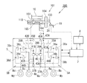
図1を参照して第1実施形態に係る倍力装置101を用いた自動車のブレーキ装置200について説明する。ブレーキ装置200は、倍力装置101と、倍力装置101に取り付けられたマスタシリンダ110の液圧ポート164、165に接続されて、各車輪Wa〜Wdの液圧ブレーキのホイールシリンダBa〜Bdにブレーキ液圧を供給する液圧制御装置5と、液圧制御装置5を制御するコントローラ7と、回生制動を行なう回生ブレーキ装置8とを備えている。
Hereinafter, embodiments of the present invention will be described in detail with reference to the drawings.
With reference to FIG. 1, the
液圧制御装置5は、マスタシリンダ110のプライマリポート164からの液圧を左前輪Wa及び右後輪Wbのブレーキ装置のホイールシリンダBa、Bbに供給するための第1液圧回路5A(図1の液圧制御装置5の中央より右側分部)と、セカンダリポート165からの液圧を右前輪Wc及び左後輪Wdのブレーキ装置のホイールシリンダBc、Bdに供給するための第2液圧回路5B(図1の液圧制御装置5の中央より左側分部)とからなる所謂「X配管」とした2系統の液圧回路を備えている。
本実施形態では、ブレーキ装置は、液圧をホイールシリンダBa〜Bdに供給してピストンを前進させ、ブレーキパッドを車輪と共に回転するディスクロータに押圧して制動力を発生させる液圧式ディスクブレーキとしているが、公知のドラムブレーキ等の他の液圧式ブレーキでもよい。
The fluid
In this embodiment, the brake device is a hydraulic disc brake that supplies hydraulic pressure to the wheel cylinders Ba to Bd to advance the piston, and presses the brake pad against the disc rotor that rotates with the wheel to generate a braking force. However, other hydraulic brakes such as a known drum brake may be used.
第1液圧回路5Aと第2液圧回路5Bとは同様の構成であり、また、各車輪Wa〜Wdのブレーキ装置Ba〜Bdに接続された液圧回路の構成は同様の構成であり、以下の説明において参照符号の添え字A及B並びにa乃至dは、それぞれ、第1液圧回路5A及び第2液圧回路5B、並びに、各車輪Wa乃至Wdに対応することを示している。
The first
液圧制御装置5には、マスタシリンダ110から各車輪Wa〜Wdのブレーキ装置Ba〜Bdのホイールシリンダへの液圧の供給を制御する電磁開閉弁である供給弁35A、35Bと、ブレーキ装置Ba〜Bdへの液圧の供給を制御する電磁開閉弁である増圧弁36a〜36dと、ブレーキ装置Ba〜Bdから液圧を解放するためのシステムリザーバ37A、37Bと、ブレーキ装置Ba〜Bdからシステムリザーバ37A、37Bへの液圧の解放を制御する電磁弁開閉弁である減圧弁38a〜38dと、ブレーキ装置のホイールシリンダBa〜Bdに液圧を供給するためポンプ39A、39Bと、ポンプ39A、39Bを駆動するポンプモータ40と、マスタシリンダ110からポンプ39A、39Bの吸込み側への液圧の供給を制御する電磁開閉弁である加圧弁41A、41Bと、ポンプ39A、39Bの下流側から上流側への逆流を防止するための逆止弁42A、42B、43A、43B、44A、44Bと、マスタシリンダ110のプライマリポート164及びセカンダリポート165の液圧を検出する液圧センサ45A、45Bとを備えている。
The hydraulic
そして、液圧制御装置5によって供給弁35A、35B、増圧弁36a〜36d、減圧弁38a〜38d、加圧弁41A、41B及びポンプモータ40の作動を制御して、次のような作動モードを実行することができる。
[通常制動モード]
通常制動時には、供給弁35A、35B及び増圧弁36a〜36dを開き、減圧弁38a〜38d、加圧弁41A、41Bを閉じることにより、マスタシリンダ2から各車輪Wa〜WdのホイールシリンダBa〜Bdに液圧を供給する。
[減圧モード]
減圧弁38a〜38dを開き、供給弁35A、35B、増圧弁36a〜36d及び加圧弁41A、41Bを閉じることにより、ホイールシリンダBa〜Bdの液圧をリザーバ37A、37Bに解放して減圧する。
[保持モード]
増圧弁36a〜36d及び減圧弁38a〜38dを閉じることにより、ホイールシリンダBa〜Bdの液圧を保持する。
[増圧モード]
増圧弁36a〜36dを開き、供給弁35A、35B、減圧弁38a〜38d及び加圧弁41A、41Bを閉じて、ポンプモータ40を作動することにより、ブレーキ液をリザーバ37A、37Bからマスタシリンダ2側へ戻してホイールシリンダBa〜Bdの液圧を増圧する。
[加圧モード]
加圧弁41A、41B及び増圧弁36a〜36dを開き、減圧弁38a〜38d及び供給弁35A、35Bを閉じて、ポンプモータ40を作動することにより、マスタシリンダ2の液圧にかかわらず、ポンプ39A、39Bによってブレーキ液をホイールシリンダBa〜Bdに供給する。
The
[Normal braking mode]
During normal braking, the
[Decompression mode]
By opening the
[Retention mode]
The hydraulic pressures of the wheel cylinders Ba to Bd are maintained by closing the
[Pressure increase mode]
The
[Pressure mode]
By opening the pressurizing
これらの作動モードを車両状態に応じて適宜実行することにより、各種ブレーキ制御を行なうことができる。例えば、制動時に接地荷重等に応じて各車輪に適切に制動力を配分する制動力配分制御、制動時に各車輪の制動力を自動的に調整して車輪のロックを防止するアンチロックブレーキ制御、走行中の車輪の横滑りを検知して、ブレーキペダル19の操作量にかかわらず各車輪に適宜自動的に制動力を付与することにより、アンダーステア及びオーバーステアを抑制して車両の挙動を安定させる車両安定性制御、坂道(特に上り坂)において制動状態を保持して発進を補助する坂道発進補助制御、発進時等において車輪の空転を防止するトラクション制御、先行車両に対して一定の車間を保持する車両追従制御、走行車線を保持する車線逸脱回避制御、障害物との衝突を回避する障害物回避制御等を実行することができる。
Various brake controls can be performed by appropriately executing these operation modes according to the vehicle state. For example, braking force distribution control that appropriately distributes the braking force to each wheel according to the ground load during braking, anti-lock brake control that automatically adjusts the braking force of each wheel during braking to prevent wheel locking, A vehicle that suppresses understeer and oversteer and stabilizes the behavior of the vehicle by detecting a side slip of a running wheel and automatically automatically applying a braking force to each wheel regardless of the operation amount of the
なお、ポンプ39A、39Bとしては、例えばプランジャポンプ、トロコイドポンプ、ギヤポンプ等の公知の液圧ポンプを用いることができるが、車載性、静粛性、ポンプ効率等を考慮するとギヤポンプとすることが望ましい。ポンプモータ40としては、例えばDCモータ、DCブラシレスモータ、ACモータ等の公知のモータを用いることができるが、制御性、静粛性、耐久性、車載性等の観点からDCブラシレスモータが望ましい。
As the
また、液圧制御装置5の電磁開閉弁の特性は、使用態様に応じて適宜設定することができるが、供給弁35A、35B及び増圧弁36a〜36dを常開弁とし、減圧弁38a〜38d及び加圧弁41A、41Bを常閉弁とすることにより、液圧制御装置6からの制御信号がない場合に、マスタシリンダ12からブレーキ装置Ba〜Bdに液圧を供給することができるので、フェイルセーフ及び制御効率の観点から、このような構成とすることが望ましい。
Further, the characteristics of the electromagnetic on-off valve of the hydraulic
回生ブレーキ装置8は、減速時及び制動時等に少なくとも1つの車輪の回転によって発電機(電動モータ)を駆動することにより、運動エネルギーを電力として回収する。回生ブレーキ装置8とコントローラ7とは、相互に制御信号の授受を行ない、運転者によるブレーキペダル19の操作によるストロークセンサ20からの信号に基き、回生制動中には回生制動分を減じたブレーキ液圧をホイールシリンダBa〜Bdに供給することにより、所望の制動力を得る回生協調制御を実行する。
The regenerative braking device 8 recovers kinetic energy as electric power by driving a generator (electric motor) by rotation of at least one wheel during deceleration and braking. The regenerative braking device 8 and the
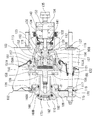
次に、図2は、第1実施形態に係る倍力装置101にマスタシリンダ110を取り付けた液圧発生装置を示している。倍力装置101は、気圧式アクチュエータを倍力源とするシングル型の気圧式倍力装置である。薄板によって形成されたフロントシェル102とリアシェル103とが結合されてハウジング104が形成され、このハウジング104内がダイアフラム105を有するパワーピストン106によって定圧室107と変圧室108との2室に区画されている。フロントシェル102及びリアシェル103は、略有底円筒状であり、これらは、フロントシェル102の外周の開口縁部に、リアシェル103の外周の開口縁部を嵌合し、これらの間にダイアフラム105の外周部を挟み込むことによって、気密的に結合されている。
Next, FIG. 2 shows a hydraulic pressure generator in which a
フロントシェル102の底部の中央開口109にマスタシリンダ110の後端部が挿入され、フロントシェル102にマスタシリンダ110が取付けられている。リアシェル103の底部の中央部には、後述するバルブボディ111(助力部材)を挿通するための後部円筒部112が突出されている。後部円筒部112の周囲には、車体のダッシュパネル(図示せず)に当接するリア座面113が形成されている。
The rear end of the
ハウジング104には、フロントシェル102からリアシェル103のリア座面113に貫通するタイロッド114が設けられている。タイロッド114は、両端部に取付ネジ部115及び固定ネジ部116が形成され、取付ネジ部115及び固定ネジ部116の基部に、それぞれ拡径されたフロントフランジ117及びリアフランジ118が形成されている。そして、フロントフランジ117がフロント座面110の内側にリテーナ119及びシール120を介して気密的に当接し、リアフランジ118がリア座面113の内側に気密的に当接した状態で、リアシェル103側にカシメによって固定されている。タイロッド114の中央部は、パワーピストン106に設けられた開口121及びダイアフラム105と一体に形成された略円筒状のロッドシール122に挿入されて、パワーピストン106及びダイアフラム105に対して摺動可能かつ気密的に貫通している。
The
タイロッド114は、フロントシェル102及びリアシェル103の直径方向2箇所に配置されており(一方のみ図示する)、取付ネジ部115によってフロントシェル102にマスタシリンダ110を固定し、固定ネジ部116によってリア座面113を上述の車体のダッシュパネル(図示せず)に固定する。また、リア座面113には、これをダッシュパネルに固定するためのリアボルト123がカシメによって固定されている。
The
パワーピストン106及びダイアフラム105の中央開口部105A、106Aに、略円筒状のバルブボディ111の前端に拡径されて形成された円筒部111Aが挿入されている。そして、ダイアフラム105の中央開口部105Aの内周縁部105Bがバルブボディ111の外周溝111Bに嵌合して、これらが気密的に結合されている。バルブボディ111の後端側の小径筒部111Cは、変圧室108を通り、リアシェル103の後部の円筒部112に挿入されて外部へ延出している。円筒部112には、シール部材124が装着されて、バルブボディ111の小径筒部111Cとの間を摺動可能にシールしている。また、円筒部112とバルブボディ111の小径筒部111Cとの間には、蛇腹状のダストカバー125が設けられている。フロントシェル102には、接続管126が取付けられており、接続管126がエンジンの吸気管等の負圧源(図示せず)に接続されて、定圧室107が常時所定の負圧に維持される。
A
バルブボディ111の前端の円筒部111Aには、反力調整機構150が設けられている。バルブボディ111は、その推力を、反力調整機構150を介して、マスタシリンダ110のプライマリピストン160(後述)に当接する出力ロッド128に伝達する。この出力ロッド128は、先端部128Aがプライマリピストン160に当接し、基端部128Bがカップ状に形成されて円板状のリアクション部材155(反力分配機構)が内包されている。出力ロッド128は、このリアクション部材155を介して反力調整機構150から力の伝達を受けるとともにマスタシリンダ110からの反力を伝達するようになっている。
A reaction
反力調整機構150は、出力ロッド128のカップ状の基端部128Bに嵌合するカップ状の保持部材151と、保持部材151内に嵌合して固定された略円筒状の反力受部材152と、反力受部材152内に軸方向に沿って移動可能に案内された略円柱状の反力伝達部材153(反力調整手段)とを備えている。保持部材151は、開口部の外周部に段付フランジ状のバネ受部151Aが一体に形成されている。バネ受部151Aは、バルブボディ111の前端部に嵌合して固定されている。上記反力受部材152は、その後端部が保持部材151の底部の開口から延出している。反力受部材152の前端部は、出力ロッドの128の基端部128Bに嵌合されて、リアクション部材155に当接している。反力伝達部材153は、軸方向中間部に形成された大径のバネ受部153Aと、反力受部材152の反力伝達部材153を案内する案内部156との間に介装された圧縮コイルばねである反力調整バネ157によってリアクション部材155側に付勢されている。案内部156は、反力受部材152に固定されている。バネ受部153Aは、反力受部材152に当接することによって前端部がリアクション部材155に当接した状態でリアクション部材155側への移動が規制されている。なお、本実施形態において、リアクション部材155は、カップ状に形成された出力ロッド128の基端部128Bに内包されるように設けられているが、反力受部材152に凹部を形成して内包するようにしてもよい。その場合、出力ロッドは、基端部128Bを円盤状としてその形状を簡略化することができる。
The reaction
バルブボディ111の後端の小径筒部111C内には、プランジャ131が、外周囲がシールされた状態で挿入されている。プランジャ131は、バルブボディ111内の拡径された円筒部と小径筒部111Cとの間に軸方向に沿って摺動可能かつ気密的に案内され、前端の小径部が反力受部材152の案内部に挿入されて反力伝達部材との間に隙間Cをもって対向している。プランジャ131には、バルブボディ111の後部から挿入された入力ロッド133(入力部材)の先端部が連結され、入力ロッド133によりプランジャ131が操作されるようになっている。入力ロッド133の基端部は、バルブボディ111の後端部に装着された通気性のダストシール134を貫通して外部へ延出されている。入力ロッド133の基端部には、ブレーキペダル19(図1参照)を連結するためのクレビス135が取付けられている。また、バルブボディ111の小径筒部111Cには、プランジャ131によって開閉弁が制御される制御バルブ132が挿入されている。制御バルブ132は、一端が入力ロッド133に係止された弁バネ141によって閉弁方向に付勢されている。
A
バルブボディ111の側壁111Dには、バルブボディ111の軸方向に延びて定圧室107に連通する定圧通路136及びバルブボディ111の径方向に延びて変圧室108に連通する変圧通路137が設けられている。制御バルブ132は、バルブボディ111とプランジャ131との相対変位に応じて変圧通路137に対する定圧通路136と大気(ダストシール134側)との接続、遮断を切換えるものである。ブレーキペダル19が操作されていない状態では、変圧通路137(すなわち変圧室108)に対して定圧通路136(すなわち定圧室107)及び大気(ダストシール134側)を遮断している。そして、ブレーキペダル19が操作されてバルブボディ111に対してプランジャ131が前進すると、変圧通路137に対して定圧通路136を遮断したまま、大気(ダストシール134側)に接続する。このとき、変圧通路137は、ダストシール134を介して大気に開放されるようになっている。
The
バルブボディ111の側壁111Dを径方向に延びる変圧通路137には、ストップキー138が挿入されている。ストップキー138は、リアシェル103の円筒部112の段部に係合することによってバルブボディ111の後退位置を制限している。また、ストップキー138は、プランジャ131の外周溝に移動可能に係合することによってバルブボディ111とプランジャ31との相対変位量を制限している。
A
フロントシェル102の前壁とバルブボディ111の前端の円筒部111Aに取付けられた上記保持部材151のバネ受部151Aとの間には、バルブボディ109を後退位置へ付勢する戻しバネ139が設けられている。また、バルブボディ111の後部側の小径筒部内には、入力ロッド133を後退位置へ付勢する戻しバネ140が設けられている。
A
反力調整機構150の保持部材151の外周部には、カップ状の押圧部材157が軸方向に沿って摺動可能に嵌合されている。押圧部材157は、底部の開口にプランジャ131の前端の小径部が挿入されて底部がプランジャ131の段部に当接している。保持部材151のバネ受部151Aの前方の戻しバネ139の内周側に環状のバネ受158が設けられている。バネ受158には、保持部材151のバネ受部151Aを貫通して延ばされて押圧部材157の前端部に当接する当接部158Aが一体に形成されている。フロントシェル102の前壁とバネ受158との間には、戻しバネ139よりも小径のテーパ状のコイルバネである反力バネ159(反力付与手段)が介装されている。本実施形態においては、このように反力バネ159と戻しバネ139との軸方向位置を合わせて配置することにより、倍力装置101の小型化を実現している。なお、反力バネ159は、テーパ状のコイルバネとしているが、これに限らず、樽型、鼓型等の種々のコイルバネやコイルドウェーブスプリング、複数の皿ばね、ゴムや樹脂からなる弾性部材などの反力付与部材を用いることができる。
A cup-shaped
マスタシリンダ110には、開口側に、先端部がカップ状に形成された円筒状のプライマリピストン160が嵌装され、底部側にカップ状のセカンダリピストン161が嵌装されている。プライマリピストン160の後端部は、マスタシリンダ110の開口部から突出して、低圧室107内において出力ロッド128の先端部に当接している。マスタシリンダ110内は、プライマリピストン160及びセカンダリピストン161によってプライマリ室162及びセカンダリ室163の2つの圧力室が形成されている。プライマリ室162及びセカンダリ室163には、液圧ポート164、165(図1参照)がそれぞれ設けられている。液圧ポート164、165は、2系統の液圧回路からなる液圧制御装置5を介して各車輪Wa〜Wdの液圧ブレーキのホイールシリンダBa〜Bdに接続されている(図1参照)。
The
マスタシリンダ110の側壁の上部には、プライマリ室162及びセカンダリ室163をリザーバ10に接続するためのリザーバポート166、167が設けられている。マスタシリンダ110のシリンダボアと、プライマリピストン160及びセカンダリピストン161との間は、それぞれ2つのシール部材168A、168B及び169A、169Bによってシールされている。シール部材168A、168Bは、軸方向に沿ってリザーバポート166を挟むように配置されている。そして、プライマリピストン160が図2に示す非制動位置にあるときに、プライマリ室162がプライマリピストン160の側壁に設けられたポート170を介してリザーバポート166に連通し、プライマリピストン160が非制動位置から所定の遊びストロークSだけ前進したとき、シール部材168Bによってプライマリ室162がリザーバポート166から遮断されてプライマリ室162が加圧される(図4参照)。同様に、シール部材169A、169Bは、軸方向に沿ってリザーバポート167を挟むように配置されている。そして、セカンダリピストン161が図2に示す非制動位置にあるとき、セカンダリ室163がセカンダリピストン161の側壁に設けられたポート171を介してリザーバポート167に連通する。セカンダリピストン161が非制動位置から所定の遊びストロークSだけ前進したとき、シール部材169Bによってセカンダリ室163がリザーバポート167から遮断されてセカンダリ室163が加圧される。
プライマリ室162内のプライマリピストン160とセカンダリピストン161との間には、バネアセンブリ172が介装されている。また、セカンダリ室163内のマスタシリンダ110の底部とセカンダリピストン161との間には、圧縮コイルバネである戻しバネ173が介装されている。バネアセンブリ172は、圧縮コイルバネを伸縮可能なリテーナによって所定の圧縮状態で保持し、そのバネ力に抗して圧縮可能としたものである。そして、プライマリピストン160及びセカンダリピストン161は、通常は同時に移動してプライマリ室162及びセカンダリ室163を同時に加圧する。
なお、上記実施の形態では、タンデムマスタシリンダを用いた例を示したが、前輪2輪を油圧制御し、後輪を電気制御するブレーキを用いる場合などは、シングルマスタシリンダを用いることも可能である。
A
In the above embodiment, an example using a tandem master cylinder is shown. However, when using a brake that hydraulically controls two front wheels and electrically controls a rear wheel, a single master cylinder can be used. is there.
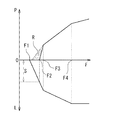
次に倍力装置101の作動について、図2乃至図5及び図8を参照して説明する。なお、図8は、入力ロッド133への入力F(ブレーキペダル19への踏力)と、マスタシリンダ110の液圧P(及び制動力)、入力ロッド133のストロークLとの関係を表している。
Next, the operation of the
図2に示す非制動状態においては、プランジャ131が図示の非制動位置にあり、定圧室107と変圧室108とは同圧となっているためパワーピストン106に推力は生じない。このとき、定圧通路136(すなわち定圧室107)と変圧通路137(すなわち変圧室108)とは、制御バルブ132によって遮断されている。
In the non-braking state shown in FIG. 2, the
ブレーキペダル19の踏込みが開始され(図8の入力F1参照)、バネ受158及び押圧部材157を介してプランジャ131に作用する反力バネ159と戻しバネ140とのバネ力に抗して、入力ロッド133によってプランジャ131を前進させると、制御バルブ132からプランジャ131が離間し、変圧通路137が大気に開放されて、変圧室108に大気が導入される。これにより、定圧室107と変圧室108との間に差圧が生じ、この差圧によってパワーピストン106に推力が発生し、バルブボディ111が前進して、リアクション部材155を介して出力ロッド128を前進させ、マスタシリンダ110のプライマリピストン160を押圧する。バルブボディ111が前進すると、制御バルブ132によって変圧通路137が大気から遮断されるので、定圧室107と変圧室108との差圧、すなわち、パワーピストン106の推力が維持されるので、バルブボディ111は、プランジャ131の移動に追従して移動することになる。
The depression of the
このとき、図3に示すように、プライマリピストン160及びセカンダリピストン161のストロークが遊びストロークSに達するまでは、マスタシリンダ110で液圧が発生せず、液圧による反力も生じないので、ブレーキペダル19には反力バネ159のバネ力による反力のみが作用する。
At this time, as shown in FIG. 3, until the stroke of the
ブレーキペダル19が更に踏込まれて、プライマリピストン160のストロークが遊びストロークSに達すると、図4に示すように、シール部材168B、169Bによってポート170、171が閉じてマスタシリンダ110で液圧が発生し(図8の入力F2参照)、その反力がリアクション部材を介して反力受部材152を介してバルブボディ111に作用する。このとき、その反力の一部がリアクション部材155を介して反力伝達部材153にも作用するが、反力伝達部材153に作用する反力が反力調整バネ157のバネ力に達するまでは、反力伝達部材153は移動せず、プランジャ131との間に隙間Cが設けられているので、プランジャ131には、マスタシリンダ110の液圧による反力は作用せず、引続き反力バネ159と戻しバネ140とのバネ力による反力のみが作用する。これにより、マスタシリンダ110の液圧に左右されない良好なブレーキペダル19の操作フィーリングを維持することができる。
When the
ブレーキペダル19が更に踏込まれ、バルブボディ111の前進により、マスタシリンダ110の液圧が上昇し、液圧による反力が増大して、リアクション部材155から反力伝達部材153に作用する反力が反力調整バネ157のバネ力を超えると、図5に示すように、反力伝達部材153が後退してプランジャ131に当接する(図8の入力F3参照)。これにより、マスタシリンダ110の液圧による反力の一部がプランジャ131に作用する。その結果、倍力比が小さくなるが、マスタシリンダ110の液圧上昇にともなう反力がブレーキペダル19に伝わり、反力バネ159のみでは得られない剛性感のあるブレーキフィーリングを与えることができる。その後、ブレーキペダル19が更に踏込まれて全負荷点に達すると(図8の入力F4参照)、倍力比が更に小さくなる。
When the
ブレーキペダルBを戻して入力ロッド133への入力を解除すると、プランジャ131が後退し、制御バルブ132によって変圧通路137が大気から遮断された状態で定圧通路136に接続され、これにより、定圧室107と変圧室108との差圧が解消され、パワーピストン106の推力が消失して、プランジャ131の移動に追従してパワーピストン106が後退して図2に示す非制動状態に戻る。
When the brake pedal B is returned and the input to the
次に、コントローラ7によるブレーキ装置200の制御について説明する。
ブレーキペダル19の踏込みが開始され、プライマリピストン160及びセカンダリピストン161のストロークが遊びストロークSに達するまでは、ストロークセンサ20によって検出した入力ロッド133(すなわちブレーキペダル19)のストロークに基づき、液圧制御装置5を作動させてホイールシリンダBa〜Bdにブレーキ液を供給し、ブレーキペダル19の操作量に応じた制動力を発生させる。このとき、反力バネ159のバネ力により、ブレーキペダル19には、その操作量に応じた反力が作用する。
Next, control of the
Until the depression of the
通常、この制動領域(図8の入力F1〜F3の領域)においては、F1から少しの遊びを経て、回生ブレーキ装置8によって回生制動が行なわれ、コントローラ7により回生協調制御を実行する。回生協調制御実行中には、ストロークセンサ20が検出する入力ロッド133のストロークに基づき決定した目標制動力に対応した回生制動分を行う。また、回生制動分で足りない分の制動力は、回生制動分を減じたブレーキ液圧をホイールシリンダBa〜Bdに供給することにより、所望の制動力を得る。
Normally, in this braking region (region of inputs F1 to F3 in FIG. 8), regenerative braking is performed by the regenerative braking device 8 through a little play from F1, and regenerative cooperative control is executed by the
このとき、入力ロッド133のストロークが遊びストロークS(図8の入力F2)に達するまでは、マスタシリンダ110で液圧が発生しないので、回生制動を最大限に活用することができ、効率よくエネルギーを回収することができる。また、液圧制御装置5による回生協調作動により、マスタシリンダ110の液圧が変動した場合でも、マスタシリンダ110のプライマリ室163及びセカンダリ室164がリザーバ10に連通しているので、マスタシリンダ110の液圧は上昇しない。このため、ブレーキペダルに液圧の反力によるキックバックが生じることがなく、ブレーキペダル19の違和感のない操作フィーリングを得ることができる。ここで、遊びストロークSの領域において、回生制動装置8が最大回生状態に達するようにすることにより、回生制動を最大限に活用することが可能になり、効率よくエネルギーを回収することができる。また、上記遊びストロークSの領域において、回生制動装置8が回生制動しないような場合には、液圧制御装置5が入力ロッド133のストロークに応じた液圧を発生するので、ブレーキペダル19操作に対して運転者が感じる減速感に違和感を憶えることを防止できる。
ここで、最大回生状態とは、車両の設計段階で設定される回生ブレーキの最大の制動力(力または加速度で表されることが多い)をいう。
At this time, no hydraulic pressure is generated in the
Here, the maximum regenerative state refers to the maximum braking force (often expressed by force or acceleration) of the regenerative brake set at the vehicle design stage.
なお、図8の入力F1〜F3の領域において、最大回生状態になること望ましいが、車速、バッテリーの充電状況、路面ミュー等に応じて、回生量は調整されるので、走行状態によって、同じ入力ロッドの入力であっても、回生量は異なる。さらには、回生が中止されることもある。 In the region of inputs F1 to F3 in FIG. 8, it is desirable that the maximum regenerative state be achieved. However, since the regenerative amount is adjusted according to the vehicle speed, the battery charging state, the road surface mu, etc., the same input depends on the traveling state. Even with rod input, the amount of regeneration is different. Furthermore, regeneration may be stopped.
ブレーキペダル19が更に踏込まれて、プライマリピストン160のストロークが遊びストロークSに達すると(図8の入力F2参照)、リザーバポートが閉じてマスタシリンダ110で液圧が発生し、液圧による反力がリアクション部材を介して反力受部材152及び反力伝達部材153に作用する。このとき、反力伝達部材153に作用する反力が反力調整バネ157のバネ力に達するまでは、反力伝達部材153は移動せず、プランジャ131との間に隙間Cが設けられているので、プランジャ131には、マスタシリンダ110の液圧による反力は作用せず、引続き反力バネ159と戻しバネ140とのバネ力による反力のみが作用する。これにより、マスタシリンダ110の液圧に左右されない良好なブレーキペダル19の操作フィーリングを維持することができる。
When the
このようにして、図8中に斜線部Rで示す領域について、マスタシリンダ液圧は発生しないものの、回生ブレーキ装置8又は液圧制御装置5によって制動力を発生させることにより、ブレーキペダル19の操作量に応じた斜線部Rのマスタシリンダ液圧が発生したとき相当の所望の制動力(図8中一点鎖線)を得ることができる。
Thus, although the master cylinder hydraulic pressure is not generated in the region indicated by the hatched portion R in FIG. 8, the braking force is generated by the regenerative braking device 8 or the hydraulic
ブレーキペダル19が更に踏込まれ、バルブボディ111の前進により、マスタシリンダ110の液圧が上昇し、液圧による反力が増大して、リアクション部材155から反力伝達部材153に作用する反力が反力調整バネ157のバネ力を超えると、図5に示すように、反力伝達部材が後退して、プランジャ131に当接する(図8の入力F3(所定のストローク位置、所定のペダル踏力)参照)。これにより、マスタシリンダ110の液圧による反力の一部がプランジャ131に作用する。
When the
このとき、回生ブレーキ装置8は、回生制動を終了し、また、コントローラにより、液圧制御装置5は通常制動モードに移行し、マスタシリンダ110の液圧をホイールシリンダBa〜Bdに供給する。これにより、倍力装置101により負圧による倍力が行なわれ、全負荷点に達する(図8の入力F4参照)。その結果、負圧による倍力により、違和感のないブレーキペダルの操作フィーリングを得ることができる。また、液圧制御装置5の第1又は第2液圧回路5A、5Bの一方の液圧系統が失陥した場合、他方の液圧系統によって液圧を発生させることができ、制動機能を維持することができる。
At this time, the regenerative braking device 8 finishes the regenerative braking, and the hydraulic
なお、上記では、図8の入力F3以上を通常制動モードとしているが、これは、通常走行中の制動を示すものではなく、液圧制御装置5や回生ブレーキ装置8による制動が行われず従前のマニュアルブレーキのようにマスタシリンダの圧力がホイールシリンダの圧力として働くモードを示している(但し、姿勢安定制御時は通常制動モードでも圧制御装置5が働く)。通常走行中のブレーキ操作は入力F3以下程度で、制動が行われる。
In the above description, the normal braking mode is set to the input F3 or higher in FIG. 8, but this does not indicate the braking during the normal traveling, and the braking by the
また、上記説明では、反力伝達部材が後退してプランジャ131に当接し、マスタシリンダ110の液圧による反力の一部がプランジャ131に作用する入力と、回生ブレーキ装置8が回生を終了する入力とを同じF3とした例を示したが、これに限らず、反力の一部がプランジャ131に作用した後であっても回生制動を続けても良い。但し、この場合は、違和感のないブレーキペダルの操作フィーリングを得るための工夫が必要となる。
Further, in the above description, the reaction force transmission member moves backward and comes into contact with the
次に、倍力装置の第2実施形態について、図6を参照して説明する。なお、以下の説明において、図2に示すものに対して、同様の部分については同一の符号を付し、異なる部分についてのみ詳細に説明する。 Next, a second embodiment of the booster will be described with reference to FIG. In the following description, the same parts as those shown in FIG. 2 are denoted by the same reference numerals, and only different parts will be described in detail.
図6は、第2実施形態に係る気圧式の倍力装置201の要部を示しており、倍力装置201では、マスタシリンダ110(図6には示さず)には、遊びストロークSは設けられていない(この点では、第1の実施の形態とは異なる)。すなわち、従前から車両に取り付けられている無効ストローク(遊びストロークS)が少ないマスタシリンダが用いられている。遊びストロークS1は、マスタシリンダ110に設ける代わりに、倍力装置201の制御バルブ132Aに設けられている。このため、図6に示すようなブレーキペダル19が操作されていない非制動位置から定圧通路136と変圧通路137とが連通されており、入力ロッド133がバルブボディ111に対して、遊びストロークS1の分だけ前進するまで、定圧通路136と変圧通路137とを遮断しないようになっている。また、反力伝達部材153とプランジャ131との間には、図2のものの隙間Cよりも大きい隙間C1が設けられている。
FIG. 6 shows a main part of a
これにより、ブレーキペダル19が踏込まれて、入力ロッド133のバルブボディ111に対する移動距離が遊びストロークS1に達するまでは、定圧室107と変圧室108との間に差圧が生じず、バルブボディ111が前進しない。また、プランジャ131が反力伝達部材153に当接しない。その結果、出力ロッド128がマスタシリンダ110のプライマリピストン160を押圧しない。
Thus, until the
ブレーキペダル19が更に踏込まれて、プライマリピストン160のストロークが遊びストロークS1に達すると、制御バルブ132Aが定圧通路136と変圧通路137とを遮断し、更にプランジャ131が前進すると、変圧通路137をダストシール134を介して大気に開放する。これにより、定圧室107と変圧室108との間に差圧が生じ、パワーピストン106に推力が発生してバルブボディ111が前進し、出力ロッド128がプライマリピストン160を推進してマスタシリンダ110でブレーキ液圧が発生する。これにより、図2に示すものと同様の作用、効果を奏する。また、マスタシリンダ110の無効ストロークを長くする必要がないので、倍力装置201に組み合わせるマスタシリンダの設定の幅が広がり、設計事項を簡略化することができる。
When the
次に、倍力装置の第3実施形態について、図7を参照して説明する。なお、以下の説明において、図2に示すものに対して、同様の部分については同一の符号を付し、異なる部分についてのみ詳細に説明する。 Next, a third embodiment of the booster will be described with reference to FIG. In the following description, the same parts as those shown in FIG. 2 are denoted by the same reference numerals, and only different parts will be described in detail.
図7に示す第3実施形態に係る倍力装置301は、気圧式のアクチュエータの代わりに、電動アクチュエータである電動モータ180を倍力源とした電動倍力装置である。バルブボディ111の外周部には、ハウジング181の内周部に電動モータ180を構成する環状のステータ182が固定され、ステータ182には、円筒状のロータ183が挿入されて軸受184によってハウジング181に回転可能に支持されている。ロータ183及びバルブボディ111には、ロータ183の回転運動を直線運動に変換する回転−直動変換機構として、ボール−ネジ機構185が設けられている。ボール−ネジ機構185は、ロータ183の後部に一体的に形成された円筒状の回転部材186と、バルブボディ111の後部に一体に形成された直動部材187と、これらの互いに対向する内周面及び外周面に形成された螺旋状のボール溝内に装填されたボール188(鋼球)とから構成されている。そして、回転部材186がロータ183と一体に回転することにより、ボール溝内でボール188が転動して直動部材187がバルブボディ111と一体に軸方向に沿って直線運動する。ハウジング181には、ロータ183の回転位置を検出するためのレゾルバ等の回転位置センサ189が設けられている。
A
そして、ブレーキペダル19に設けられたストロークセンサ20(図1参照)によって入力ロッド133のストロークに基づき、電動モータ180の作動を制御し、ボール−ネジ機構185を介してバルブボディ111を推進して入力ロッド133に追従させる。これにより、出力ロッド128により、マスタシリンダ110のプライマリピストン160を推進して液圧を発生させる。これにより、図2に示すものと同様の作用、効果を奏することができる。
Then, the stroke sensor 20 (see FIG. 1) provided on the
なお、上記実施形態において、負圧源をエンジンの吸気管としたが、これに限らず負圧ポンプ等であってもよい。さらに、倍力装置は、倍力源として、気圧式アクチュエータ、電動アクチュエータを用いた場合について説明しているが、これに限らず、液圧式その他のアクチュエータを用いてもよい。 In the above embodiment, the negative pressure source is the intake pipe of the engine. However, the present invention is not limited to this, and a negative pressure pump or the like may be used. Further, the booster device has been described with respect to the case where a pneumatic actuator or an electric actuator is used as a boost source.
上記各実施形態の倍力装置においては、ブレーキペダルの操作によって移動する入力部材と、該入力部材に対して進退動可能な助力部材と、前記入力部材の移動により前記助力部材を推進して前記入力部材に追従させるアクチュエータと、前記入力部材及び前記助力部材の推力を合成して、マスタシリンダのピストンに伝達し、該ピストンからの反力を前記入力部材と前記助力部材とに分配する反力分配機構と、前記入力部材の推進に対して反力を付与する反力付与手段とを備え、前記入力部材は、前記ブレーキペダルの操作により前記マスタシリンダに液圧が発生してから前記アクチュエータの推力が全負荷状態となるまでの間に、初期位置から所定ストローク分だけ移動するまでは、前記反力分配機構から反力を受けず、更なるストロークに対して、前記反力分配機構から反力を受けるようになっている。 In the booster of each of the above embodiments, the input member that moves by operating the brake pedal, the assisting member that can move forward and backward with respect to the input member, and the assisting member that propels the assisting member by moving the input member. The actuator that follows the input member and the thrust of the input member and the assisting member are combined and transmitted to the piston of the master cylinder, and the reaction force that distributes the reaction force from the piston to the input member and the assisting member A distribution mechanism; and a reaction force applying unit that applies a reaction force to the propulsion of the input member. The input member is configured to operate the actuator after hydraulic pressure is generated in the master cylinder by operating the brake pedal. Until the thrust reaches the full load state, no further reaction force is received from the reaction force distribution mechanism until it moves by a predetermined stroke from the initial position. Respect, and adapted to receive a reaction force from the reaction force distribution mechanism.
上記構成によれば、回生協調時にブレーキペダルの反力の変動を低減してブレーキペダルの操作フィーリングを改善することができる。 According to the said structure, the fluctuation | variation of the reaction force of a brake pedal can be reduced at the time of regeneration cooperation, and the operation feeling of a brake pedal can be improved.
上記第1及び第2実施形態の倍力装置においては、前記アクチュエータは、気圧式アクチュエータとなっている。
上記第3実施形態の倍力装置においては、前記アクチュエータは電動アクチュエータとなっている。
In the booster of the first and second embodiments, the actuator is a pneumatic actuator.
In the booster of the third embodiment, the actuator is an electric actuator.
上記各実施形態の倍力装置においては、前記マスタシリンダには、液圧の供給によって制動力を発生させるホイールシリンダが、前記ホイールシリンダに供給する液圧を制御する液圧制御装置を介して接続され、回生ブレーキ装置と組み合わせて使用されて、前記液圧制御装置によって回生制動分に応じて前記ホイールシリンダに供給する液圧を制御することにより回生協調制御を実行可能となっており、前記回生ブレーキ装置による回生制動分が所定の最大回生状態に達した後、前記入力部材に液圧の反力が伝達されるように設定されている。 In the booster of each of the embodiments described above, a wheel cylinder that generates a braking force by supplying hydraulic pressure is connected to the master cylinder via a hydraulic control device that controls hydraulic pressure supplied to the wheel cylinder. The regenerative brake control is executed by controlling the hydraulic pressure supplied to the wheel cylinder according to the regenerative braking by the hydraulic pressure control device. After the amount of regenerative braking by the brake device reaches a predetermined maximum regenerative state, the reaction force of the hydraulic pressure is transmitted to the input member.
なお、ここで、最大回生状態に達した後とは、どのような走行状態であっても最大回生状態に達成した後であることを意味するわけではない。これは、車両の設計段階で、回生ブレーキ装置による最大制動力(例えば、0.1G)と、それを発生させるためのペダル踏力(入力ロッド入力)が設定され、このペダル踏力より大きなペダル踏力(F3)において、入力部材にマスタシリンダの液圧の反力が伝達されるように反力分配機構や反力付与手段が設定されていることを意味する。 Here, “after reaching the maximum regeneration state” does not mean that the vehicle has reached the maximum regeneration state in any driving state. This is because at the vehicle design stage, the maximum braking force (for example, 0.1 G) by the regenerative braking device and the pedal depression force (input rod input) for generating the braking force are set. F3) means that the reaction force distribution mechanism and the reaction force applying means are set so that the reaction force of the hydraulic pressure of the master cylinder is transmitted to the input member.
上記構成によれば、回生協調時にブレーキペダルの反力の変動を低減してブレーキペダルの操作フィーリングを改善することができる。 According to the said structure, the fluctuation | variation of the reaction force of a brake pedal can be reduced at the time of regeneration cooperation, and the operation feeling of a brake pedal can be improved.
上記各実施形態の倍力装置においては、前記入力部材の前記所定ストロークは、初期位置から前記液圧制御装置による回生協調制御が終了する位置に達した位置までの長さとなっている。なお、前記所定ストロークは、適宜設定可能である。 In the booster of each of the embodiments described above, the predetermined stroke of the input member is a length from an initial position to a position where the regenerative cooperative control by the hydraulic pressure control device has been completed. The predetermined stroke can be set as appropriate.
上記第1及び第2実施形態の倍力装置においては、パワーピストンによって定圧室と変圧室とに画成されるハウジングと、ハウジング内に進退動可能に設けられ、前記パワーピストンに連結されたバルブボディと、前記バルブボディに進退動可能に挿入され、ブレーキペダルに連結される入力ロッドと、前記バルブボディ内に配置されて前記入力ロッドに連結されたプランジャと、前記プランジャの移動によって開閉して前記変圧室に作動気体を導入、排出するための弁手段と、前記パワーピストンの推力がリアクション部材を介して伝達される出力ロッドと、前記入力ロッドの推進に対して反力を付与する反力付与手段と、前記リアクション部材と前記プランジャとの間に配置されて前記リアクション部材から前記プランジャに伝達される反力を調整する反力調整手段と、を備え、前記プランジャは、前記反力調整手段との間に隙間が設けられ、前記入力ロッドが初期位置から所定ストローク分だけ移動するまでは前記反力調整手段に当接せず、前記反力調整手段は、前記出力ロッドからの反力が所定分だけ増大したとき、前記プランジャに当接して前記リアクション部材から前記プランジャに反力を伝達するようになっている。 In the booster of the first and second embodiments, a housing defined by a power piston into a constant pressure chamber and a variable pressure chamber, a valve that is provided in the housing so as to be able to move forward and backward, and is connected to the power piston. A body, an input rod which is inserted into the valve body so as to be movable back and forth, and is connected to a brake pedal; a plunger which is arranged in the valve body and connected to the input rod; and is opened and closed by movement of the plunger Valve means for introducing and discharging the working gas into the variable pressure chamber, an output rod through which the thrust of the power piston is transmitted via a reaction member, and a reaction force that provides a reaction force against the propulsion of the input rod It is arrange | positioned between a provision means, the said reaction member, and the said plunger, and is transmitted to the said plunger from the said reaction member Comprising a reaction force adjusting means for adjusting the force of the plunger, the gap is provided between the reaction force adjustment means, the reaction force adjustment to said input rod is moved from the initial position by a predetermined stroke The reaction force adjusting means comes into contact with the plunger and transmits the reaction force from the reaction member to the plunger when the reaction force from the output rod increases by a predetermined amount. ing.
上記構成によれば、回生協調時にブレーキペダルの反力の変動を軽減してブレーキペダルの操作フィーリングを改善することができる。 According to the said structure, the fluctuation | variation of the reaction force of a brake pedal can be reduced at the time of regeneration cooperation, and the operation feeling of a brake pedal can be improved.
上記第1及び第2実施形態の倍力装置においては、前記出力ロッドは、マスタシリンダのピストンを推進し、前記マスタシリンダは、前記ピストンが初期位置から所定の遊びストロークに達した後、液圧を発生し、前記プランジャは、前記ピストンが遊びストロークに達した後、前記反力調整手段に当接するようになっている。 In the booster according to the first and second embodiments, the output rod propels the piston of a master cylinder, and the master cylinder performs hydraulic pressure after the piston reaches a predetermined idle stroke from the initial position. And the plunger comes into contact with the reaction force adjusting means after the piston reaches a play stroke.
上記第1及び第2実施形態の倍力装置においては、前記マスタシリンダには、液圧の供給によって制動力を発生させるホイールシリンダが、前記ホイールシリンダに供給する液圧を制御する液圧制御装置を介して接続され、回生ブレーキ制動装置と組み合わせて使用されて、前記液圧制御装置によって回生制動分に応じて前記ホイールシリンダに供給する液圧を制御することにより回生協調制御を実行可能な倍力装置であって、前記回生ブレーキ装置による回生制動分が所定の最大回生状態に達した後、前記プランジャが前記反力調整手段に当接するようになっている。 In the booster of the first and second embodiments, a hydraulic pressure control device that controls the hydraulic pressure supplied to the wheel cylinder by a wheel cylinder that generates a braking force by supplying hydraulic pressure to the master cylinder. Is used in combination with a regenerative brake braking device, and is capable of executing regenerative cooperative control by controlling the hydraulic pressure supplied to the wheel cylinder according to the regenerative braking by the hydraulic pressure control device. The force device is configured such that after the regenerative braking by the regenerative brake device reaches a predetermined maximum regenerative state, the plunger comes into contact with the reaction force adjusting means.
上記第1及び第2実施形態の倍力装置においては、前記入力ロッドのストロークが前記液圧制御装置による回生協調制御が終了する位置に達したとき、前記プランジャが前記反力調整手段に当接するようになっている。 In the booster of the first and second embodiments, when the stroke of the input rod reaches a position where the regenerative cooperative control by the hydraulic pressure control device ends, the plunger comes into contact with the reaction force adjusting means. It is like that.
上記第2実施形態の倍力装置においては、前記弁手段は、前記入力ロッドのストロークが所定ストロークに達するまで、前記変圧室に作動気体を導入しないようになっている。 In the booster of the second embodiment, the valve means does not introduce the working gas into the variable pressure chamber until the stroke of the input rod reaches a predetermined stroke.
上記構成によれば、マスタシリンダの無効ストロークを長くする必要がないので、倍力装置に組み合わせるマスタシリンダの設定の幅が広がり、設計事項を簡略化することができる。 According to the above configuration, since it is not necessary to lengthen the invalid stroke of the master cylinder, the setting range of the master cylinder combined with the booster can be widened, and the design matters can be simplified.
上記各実施形態のブレーキ装置においては、少なくとも1つの車輪に回生制動力を発生させる回生ブレーキ装置を有する車両に用いられ、ピストンの推進により液圧を発生させるマスタシリンダと、ブレーキペダルの操作力を入力部材に入力し、この入力を倍力して前記マスタシリンダのピストンを推進し、前記入力部材の推進に対して反力を付与する反力付与手段を有する倍力装置と、前記ブレーキペダルのストロークを検出するストロークセンサと、前記マスタシリンダと、液圧の供給により車輪を制動するホイールシリンダとの間に介装されて、前記ホイールシリンダに供給する液圧を制御する液圧制御装置と、前記ブレーキペダルのストロークに応じた制動力を前記回生ブレーキ装置による制動力と前記液圧制御装置から前記ホイールシリンダへの液圧の供給による制動力の配分によって発生させる回生協調手段と、を備えた車両用のブレーキ装置であって、前記マスタシリンダ及び前記倍力装置の少なくとも一方は、前記ブレーキペダルが初期位置から、前記回生ブレーキ装置の制動力が所定の最大回生状態に達する所定の最大回生位置を超えてストロークするまで、前記マスタシリンダが液圧を発生しないように構成され、前記倍力装置は、前記マスタシリンダの液圧が所定液圧に達するまで、又は、前記ブレーキペダルのストロークが最大回生位置に達するまでは、前記マスタシリンダの液圧による反力を受けず、前記マスタシリンダの液圧が所定液圧に達した後、又は、前記ブレーキペダルのストロークが最大回生位置に達した後は、前記マスタシリンダの液圧による反力を受けるようになっている。
なお、上記各実施の形態では、液圧制御装置5を設けた例を示したが、回生ブレーキとの協調機能をマスタシリンダ側に設けることで、液圧制御装置5を無くすことも可能である。
In the brake device of each of the above embodiments, a master cylinder that is used in a vehicle having a regenerative braking device that generates a regenerative braking force on at least one wheel and that generates hydraulic pressure by propulsion of the piston, and an operating force of the brake pedal A booster having a reaction force applying means that inputs the input member, boosts the input to propel the piston of the master cylinder, and applies a reaction force to the propulsion of the input member; and the brake pedal A hydraulic pressure control device for controlling the hydraulic pressure supplied to the wheel cylinder, interposed between a stroke sensor for detecting a stroke, the master cylinder, and a wheel cylinder for braking the wheel by supplying hydraulic pressure; The braking force according to the stroke of the brake pedal is changed from the braking force by the regenerative braking device and the hydraulic pressure control device to the wheel. And a regenerative cooperative means that is generated by distributing braking force by supplying hydraulic pressure to the cylinder, wherein at least one of the master cylinder and the booster has an initial brake pedal. The master cylinder is configured not to generate hydraulic pressure until a stroke exceeds a predetermined maximum regenerative position at which a braking force of the regenerative brake device reaches a predetermined maximum regenerative state from a position. Until the hydraulic pressure of the master cylinder reaches a predetermined hydraulic pressure or until the stroke of the brake pedal reaches the maximum regenerative position, the reaction pressure due to the hydraulic pressure of the master cylinder is not received, and the hydraulic pressure of the master cylinder is reduced. After reaching the predetermined hydraulic pressure, or after the brake pedal stroke reaches the maximum regeneration position, the hydraulic pressure of the master cylinder is increased. It is adapted to receive a reaction force that.
In each of the above embodiments, the example in which the hydraulic
19…ブレーキペダル、101、201、301…倍力装置、110…マスタシリンダ、111…バルブボディ(助力部材)、133…入力ロッド(入力部材)、155…リアクション部材(反力分配機構)、159…反力バネ(反力付与手段)、160…プライマリピストン(ピストン)、200…ブレーキ装置
DESCRIPTION OF
Claims (12)
該入力部材に対して進退動可能な助力部材と、
前記入力部材の移動により前記助力部材を推進して前記入力部材に追従させるアクチュエータと、
前記入力部材及び前記助力部材の推力を合成して、マスタシリンダのピストンに伝達し、該ピストンからの反力を前記入力部材と前記助力部材とに分配する反力分配機構と、
前記入力部材の推進に対して反力を付与する反力付与手段とを備え、
前記入力部材は、初期位置から前記ブレーキペダルの操作により前記マスタシリンダに液圧が発生した後の所定ストローク位置に移動するまで前記反力分配機構から反力を受けず、更なるストロークに対して前記反力分配機構から反力を受けるようになっていることを特徴とする倍力装置。 An input member that is moved by operating the brake pedal;
An assisting member capable of moving forward and backward with respect to the input member;
An actuator for propelling the assisting member by following the input member by moving the input member;
A reaction force distribution mechanism that synthesizes thrusts of the input member and the assisting member, transmits the thrust to the piston of the master cylinder, and distributes the reaction force from the piston to the input member and the assisting member;
Reaction force applying means for applying a reaction force to the propulsion of the input member,
The input member does not receive a reaction force from the reaction force distribution mechanism until the input member moves from the initial position to a predetermined stroke position after hydraulic pressure is generated in the master cylinder by operating the brake pedal. A booster characterized by receiving a reaction force from the reaction force distribution mechanism.
前記回生ブレーキ装置による回生制動分が最大回生状態に達した後に、前記入力部材の所定のストローク位置を設定したことを特徴とする倍力装置。 The booster according to any one of claims 1 to 3, which is used in combination with a regenerative brake device,
The booster according to claim 1, wherein a predetermined stroke position of the input member is set after the regenerative braking by the regenerative brake device reaches a maximum regenerative state.
ハウジング内に進退動可能に設けられ、前記パワーピストンに連結されたバルブボディと、
前記バルブボディに進退動可能に挿入され、ブレーキペダルに連結される入力ロッドと、
前記バルブボディ内に配置されて前記入力ロッドに連結されたプランジャと、前記プランジャの移動によって開閉して前記変圧室に作動気体を導入、排出するための弁手段と、
前記パワーピストンの推力がリアクション部材を介して伝達される出力ロッドと、
前記入力ロッドの推進に対して反力を付与する反力付与手段と、
前記リアクション部材と前記プランジャとの間に配置されて前記リアクション部材から前記プランジャに伝達される反力を調整する反力調整手段と、を備え、
前記プランジャは、前記反力調整手段との間に隙間が設けられ、前記入力ロッドが初期位置から所定ストローク位置に移動するまでは前記反力調整手段に当接せず、前記反力調整手段は、前記出力ロッドからの反力が所定分だけ増大したとき、前記プランジャに当接して前記リアクション部材から前記プランジャに反力を伝達することを特徴とする気圧式の倍力装置。 A housing defined by a power piston into a constant pressure chamber and a variable pressure chamber;
A valve body provided in the housing so as to be movable back and forth and connected to the power piston;
An input rod that is inserted into the valve body so as to be movable back and forth, and is connected to a brake pedal;
A plunger disposed in the valve body and connected to the input rod; and valve means for opening and closing the plunger by moving the plunger to introduce and discharge the working gas into the variable pressure chamber;
An output rod through which a thrust of the power piston is transmitted via a reaction member;
Reaction force applying means for applying a reaction force to the propulsion of the input rod;
A reaction force adjusting means that is arranged between the reaction member and the plunger and adjusts a reaction force transmitted from the reaction member to the plunger;
The plunger, the gap is provided between the reaction force adjustment means, to said input rod is moved from the initial position to a predetermined stroke position does not abut on the reaction force adjustment means, the reaction force adjustment means When the reaction force from the output rod increases by a predetermined amount, the reaction force is transmitted from the reaction member to the plunger in contact with the plunger.
前記回生ブレーキ装置による回生制動分が最大回生状態に達した後に、前記プランジャが前記反力調整手段に当接することを特徴とする倍力装置。 The booster according to claim 7, which is used in combination with a regenerative brake braking device,
The booster according to claim 1, wherein the plunger comes into contact with the reaction force adjusting means after the regenerative braking by the regenerative brake device reaches a maximum regenerative state.
ピストンの推進により液圧を発生させるマスタシリンダと、
ブレーキペダルの操作力を入力部材に入力し、この入力を倍力して前記マスタシリンダのピストンを推進し、前記入力部材の推進に対して反力を付与する反力付与手段を有する倍力装置と、
前記ブレーキペダルのストロークを検出するストロークセンサと、
前記マスタシリンダと、液圧の供給により車輪を制動するホイールシリンダとの間に介装されて、前記ホイールシリンダに供給する液圧を制御する液圧制御装置と、
前記ブレーキペダルのストロークに応じた制動力を前記回生ブレーキ装置による制動力と前記液圧制御装置から前記ホイールシリンダへの液圧の供給による制動力の配分によって発生させる回生協調手段と、を備えた車両用のブレーキ装置であって、
前記マスタシリンダ及び前記倍力装置の少なくとも一方は、前記ブレーキペダルが初期位置から前記マスタシリンダに液圧が発生するまでは、前記マスタシリンダの液圧による反力を前記ブレーキペダルに与えず、前記マスタシリンダの液圧が上昇し所定液圧に達した後、又は、前記ブレーキペダルのストロークが前記マスタシリンダの液圧が発生し後の所定ストローク位置に移動した後に、前記マスタシリンダの液圧による反力を前記ブレーキペダルに与えるようになっていることを特徴とするブレーキ装置。 Used in a vehicle having a regenerative braking device for generating a regenerative braking force on at least one wheel;
A master cylinder that generates hydraulic pressure by propulsion of the piston;
A booster having a reaction force applying means for inputting an operating force of a brake pedal to an input member, boosting the input to propel the piston of the master cylinder, and applying a reaction force to the propulsion of the input member. When,
A stroke sensor for detecting a stroke of the brake pedal;
A fluid pressure control device that is interposed between the master cylinder and a wheel cylinder that brakes the wheel by supplying fluid pressure, and that controls fluid pressure supplied to the wheel cylinder;
Regenerative coordination means for generating braking force according to the stroke of the brake pedal by distributing braking force by the regenerative braking device and braking force by supplying hydraulic pressure from the hydraulic pressure control device to the wheel cylinder; A brake device for a vehicle,
At least one of the master cylinder and the booster does not apply a reaction force due to the hydraulic pressure of the master cylinder to the brake pedal until hydraulic pressure is generated in the master cylinder from the initial position of the brake pedal, After the hydraulic pressure of the master cylinder rises and reaches a predetermined hydraulic pressure, or after the stroke of the brake pedal moves to a predetermined stroke position after the hydraulic pressure of the master cylinder is generated, the hydraulic pressure of the master cylinder A brake device characterized in that a reaction force is applied to the brake pedal.
Priority Applications (4)
| Application Number | Priority Date | Filing Date | Title |
|---|---|---|---|
| JP2011023869A JP5682008B2 (en) | 2011-02-07 | 2011-02-07 | Booster and brake device using the same |
| US13/366,609 US9896074B2 (en) | 2011-02-07 | 2012-02-06 | Booster and brake apparatus using the same |
| CN201210024744.8A CN102627103B (en) | 2011-02-07 | 2012-02-06 | Step-up system |
| DE102012201777A DE102012201777A1 (en) | 2011-02-07 | 2012-02-07 | amplifier |
Applications Claiming Priority (1)
| Application Number | Priority Date | Filing Date | Title |
|---|---|---|---|
| JP2011023869A JP5682008B2 (en) | 2011-02-07 | 2011-02-07 | Booster and brake device using the same |
Publications (3)
| Publication Number | Publication Date |
|---|---|
| JP2012162173A JP2012162173A (en) | 2012-08-30 |
| JP2012162173A5 JP2012162173A5 (en) | 2014-02-13 |
| JP5682008B2 true JP5682008B2 (en) | 2015-03-11 |
Family
ID=46547210
Family Applications (1)
| Application Number | Title | Priority Date | Filing Date |
|---|---|---|---|
| JP2011023869A Active JP5682008B2 (en) | 2011-02-07 | 2011-02-07 | Booster and brake device using the same |
Country Status (4)
| Country | Link |
|---|---|
| US (1) | US9896074B2 (en) |
| JP (1) | JP5682008B2 (en) |
| CN (1) | CN102627103B (en) |
| DE (1) | DE102012201777A1 (en) |
Families Citing this family (20)
| Publication number | Priority date | Publication date | Assignee | Title |
|---|---|---|---|---|
| DE102012203698A1 (en) * | 2012-03-08 | 2013-09-12 | Robert Bosch Gmbh | Method for operating a brake booster of a vehicle and control device for a brake booster of a vehicle |
| FR2995854B1 (en) * | 2012-09-27 | 2015-05-01 | Valeo Systemes Dessuyage | DEVICE FOR ACTUATING A GLASS WIPING SYSTEM, IN PARTICULAR A WINDSHIELD OF A MOTOR VEHICLE, AND A WIPING SYSTEM COMPRISING SUCH A DEVICE |
| KR102113370B1 (en) * | 2013-04-30 | 2020-05-20 | 히다치 오토모티브 시스템즈 가부시키가이샤 | Electric booster device |
| US9260091B2 (en) * | 2013-07-16 | 2016-02-16 | Ford Global Technologies, Llc | Method and system for reducing vacuum consumption in a vehicle |
| JP2015020643A (en) * | 2013-07-22 | 2015-02-02 | 日立オートモティブシステムズ株式会社 | Brake control device |
| JP2015051672A (en) * | 2013-09-05 | 2015-03-19 | 日立オートモティブシステムズ株式会社 | Brake system, brake device, and brake control method |
| DE112014005364A5 (en) * | 2013-11-25 | 2016-08-11 | Schaeffler Technologies AG & Co. KG | Piston-cylinder unit |
| DE102014217433A1 (en) * | 2014-09-01 | 2016-03-03 | Robert Bosch Gmbh | Brake booster for a brake system of a vehicle |
| DE102015200106B3 (en) * | 2015-01-08 | 2016-05-12 | Ford Global Technologies, Llc | Control method for a hydraulic brake system of a motor vehicle and hydraulic brake system |
| JP6332181B2 (en) * | 2015-07-16 | 2018-05-30 | トヨタ自動車株式会社 | Vehicle control device |
| DE102016200853A1 (en) * | 2016-01-21 | 2017-07-27 | Volkswagen Aktiengesellschaft | Method and control device for a self-braking of a motor vehicle |
| CA3014734A1 (en) * | 2016-02-22 | 2017-08-31 | Ravi G. ATHALYE | Spring based regenerative braking system |
| CN106004826B (en) * | 2016-06-03 | 2018-09-18 | 天津英创汇智汽车技术有限公司 | The braking method of the half decoupling braking system for new-energy automobile regenerative braking |
| WO2019003537A1 (en) * | 2017-06-28 | 2019-01-03 | 日信工業株式会社 | Vehicle brake system |
| JP6834853B2 (en) * | 2017-08-31 | 2021-02-24 | トヨタ自動車株式会社 | Vehicle control device |
| JP6950407B2 (en) * | 2017-09-28 | 2021-10-13 | 株式会社アドヴィックス | Vehicle braking control device |
| CN108909691B (en) * | 2018-07-19 | 2024-02-23 | 宁波域想线控底盘有限公司 | Pedal input rod structure of automobile brake booster system |
| DE102019134583A1 (en) * | 2019-12-16 | 2021-06-17 | Bombardier Transportation Gmbh | METHOD FOR ASSISTANT IN THE CONTROL OF A SPEED OF A RAIL VEHICLE, METHOD FOR ASSISTED CONTROL OF A SPEED OF A RAIL VEHICLE AND THE ASSOCIATED RAIL VEHICLE |
| DE102020109452A1 (en) * | 2020-04-03 | 2021-10-07 | Zf Active Safety Gmbh | Electrically controllable actuation unit for a motor vehicle brake, brake booster with such an electrically controllable actuation unit and motor vehicle brake system with such a brake booster |
| CN111907499B (en) * | 2020-08-07 | 2021-06-08 | 格陆博科技有限公司 | Electro-hydraulic braking system and braking method thereof |
Family Cites Families (19)
| Publication number | Priority date | Publication date | Assignee | Title |
|---|---|---|---|---|
| US7019A (en) * | 1850-01-15 | Improvement in obstetrical supporters | ||
| DE2702819A1 (en) * | 1977-01-25 | 1978-07-27 | Bosch Gmbh Robert | BRAKE AMPLIFIER FOR AN ANALYSIS PROTECTION MONITORED VEHICLE BRAKE SYSTEM |
| JPH0722368Y2 (en) * | 1987-02-12 | 1995-05-24 | 自動車機器株式会社 | Brake booster |
| DE3842225A1 (en) * | 1988-12-15 | 1990-06-21 | Bosch Gmbh Robert | BRAKE SYSTEM |
| JP3570437B2 (en) * | 1994-10-14 | 2004-09-29 | 株式会社ボッシュオートモーティブシステム | Negative pressure booster |
| GB2348683B (en) | 1996-05-31 | 2000-11-22 | Jidosha Kiki Co | Reaction mechanism for booster |
| JP3680969B2 (en) * | 1996-10-25 | 2005-08-10 | 株式会社ボッシュオートモーティブシステム | Brake booster |
| JP2001026264A (en) * | 1999-05-10 | 2001-01-30 | Bosch Braking Systems Co Ltd | Idle stroke shortening device in brake system |
| US7021724B2 (en) * | 2003-07-01 | 2006-04-04 | Nissin Kogyo Co., Ltd. | Vacuum booster |
| JP4654722B2 (en) * | 2005-03-22 | 2011-03-23 | 株式会社アドヴィックス | Brake device for vehicle |
| JP4692837B2 (en) * | 2005-06-30 | 2011-06-01 | 日立オートモティブシステムズ株式会社 | Electric booster |
| JP5012542B2 (en) * | 2007-03-27 | 2012-08-29 | 株式会社アドヴィックス | Brake device for vehicle |
| US8025345B2 (en) * | 2007-03-27 | 2011-09-27 | Advics Co., Ltd. | Vehicle brake system |
| JP5063409B2 (en) | 2008-02-27 | 2012-10-31 | 日立オートモティブシステムズ株式会社 | Brake control device |
| JP4936012B2 (en) * | 2008-04-23 | 2012-05-23 | 日立オートモティブシステムズ株式会社 | Stroke simulator |
| JP5333726B2 (en) * | 2008-10-31 | 2013-11-06 | 日立オートモティブシステムズ株式会社 | Pneumatic booster |
| JP5293418B2 (en) * | 2009-06-03 | 2013-09-18 | トヨタ自動車株式会社 | Brake abnormality detection device |
| JP2011023869A (en) | 2009-07-14 | 2011-02-03 | Fuji Xerox Co Ltd | Image reading apparatus, and image forming apparatus |
| JP6012225B2 (en) * | 2012-03-30 | 2016-10-25 | 日立オートモティブシステムズ株式会社 | Brake device |
-
2011
- 2011-02-07 JP JP2011023869A patent/JP5682008B2/en active Active
-
2012
- 2012-02-06 CN CN201210024744.8A patent/CN102627103B/en active Active
- 2012-02-06 US US13/366,609 patent/US9896074B2/en active Active
- 2012-02-07 DE DE102012201777A patent/DE102012201777A1/en active Pending
Also Published As
| Publication number | Publication date |
|---|---|
| US9896074B2 (en) | 2018-02-20 |
| CN102627103A (en) | 2012-08-08 |
| JP2012162173A (en) | 2012-08-30 |
| US20120200147A1 (en) | 2012-08-09 |
| CN102627103B (en) | 2016-12-14 |
| DE102012201777A1 (en) | 2012-08-09 |
Similar Documents
| Publication | Publication Date | Title |
|---|---|---|
| JP5682008B2 (en) | Booster and brake device using the same | |
| JP6012225B2 (en) | Brake device | |
| JP5891145B2 (en) | Brake control device | |
| US8833072B2 (en) | Hydraulic brake booster comprising a motor | |
| JP5800951B2 (en) | Brake device | |
| US8978377B2 (en) | Cylinder device | |
| US9079572B2 (en) | Main brake cylinder for a hydraulic vehicle brake system and method for operating same | |
| KR20110110334A (en) | Electrohydraulic brake system and method for operating the same | |
| WO2012060238A1 (en) | Electric booster | |
| JP5569688B2 (en) | Brake device | |
| JP2009173266A (en) | Electrically driven brake booster and tandem master cylinder | |
| JP2014046857A (en) | Electric booster | |
| EP2749466B1 (en) | Tandem Master cylinder | |
| JP3783918B2 (en) | Brake fluid pressure generator | |
| JP5770937B2 (en) | Pneumatic booster and brake device | |
| JP5716901B2 (en) | Pneumatic booster | |
| JP5828688B2 (en) | Stroke simulator and electric actuator | |
| JP5780822B2 (en) | Pneumatic booster | |
| JP2013075596A (en) | Pneumatic booster | |
| US6213569B1 (en) | Pressure generator | |
| JP5263087B2 (en) | Cylinder device | |
| WO2018139529A1 (en) | Electric brake device | |
| JP5875322B2 (en) | Brake device | |
| WO2017047312A1 (en) | Brake device and brake system | |
| JP3407553B2 (en) | Master cylinder with booster and hydraulic brake system |
Legal Events
| Date | Code | Title | Description |
|---|---|---|---|
| A521 | Request for written amendment filed |
Free format text: JAPANESE INTERMEDIATE CODE: A523 Effective date: 20131220 |
|
| A621 | Written request for application examination |
Free format text: JAPANESE INTERMEDIATE CODE: A621 Effective date: 20131220 |
|
| A977 | Report on retrieval |
Free format text: JAPANESE INTERMEDIATE CODE: A971007 Effective date: 20141006 |
|
| TRDD | Decision of grant or rejection written | ||
| A01 | Written decision to grant a patent or to grant a registration (utility model) |
Free format text: JAPANESE INTERMEDIATE CODE: A01 Effective date: 20141126 |
|
| A61 | First payment of annual fees (during grant procedure) |
Free format text: JAPANESE INTERMEDIATE CODE: A61 Effective date: 20141222 |
|
| R150 | Certificate of patent or registration of utility model |
Ref document number: 5682008 Country of ref document: JP Free format text: JAPANESE INTERMEDIATE CODE: R150 |
|
| R250 | Receipt of annual fees |
Free format text: JAPANESE INTERMEDIATE CODE: R250 |
|
| S533 | Written request for registration of change of name |
Free format text: JAPANESE INTERMEDIATE CODE: R313533 |
|
| R350 | Written notification of registration of transfer |
Free format text: JAPANESE INTERMEDIATE CODE: R350 |
|
| R250 | Receipt of annual fees |
Free format text: JAPANESE INTERMEDIATE CODE: R250 |
|
| R250 | Receipt of annual fees |
Free format text: JAPANESE INTERMEDIATE CODE: R250 |
|
| R250 | Receipt of annual fees |
Free format text: JAPANESE INTERMEDIATE CODE: R250 |