JP5679552B2 - Lever type connector - Google Patents
Lever type connector Download PDFInfo
- Publication number
- JP5679552B2 JP5679552B2 JP2010233821A JP2010233821A JP5679552B2 JP 5679552 B2 JP5679552 B2 JP 5679552B2 JP 2010233821 A JP2010233821 A JP 2010233821A JP 2010233821 A JP2010233821 A JP 2010233821A JP 5679552 B2 JP5679552 B2 JP 5679552B2
- Authority
- JP
- Japan
- Prior art keywords
- lever
- housing
- peak
- type connector
- lock
- Prior art date
- Legal status (The legal status is an assumption and is not a legal conclusion. Google has not performed a legal analysis and makes no representation as to the accuracy of the status listed.)
- Expired - Fee Related
Links
- 238000003780 insertion Methods 0.000 description 10
- 230000037431 insertion Effects 0.000 description 10
- 210000000078 claw Anatomy 0.000 description 4
- 238000012856 packing Methods 0.000 description 3
- 229920003002 synthetic resin Polymers 0.000 description 3
- 239000000057 synthetic resin Substances 0.000 description 3
- 230000008646 thermal stress Effects 0.000 description 3
- 238000010586 diagram Methods 0.000 description 1
- 239000000463 material Substances 0.000 description 1
- 239000011435 rock Substances 0.000 description 1
- 230000009466 transformation Effects 0.000 description 1
Images


Classifications
-
- H—ELECTRICITY
- H01—ELECTRIC ELEMENTS
- H01R—ELECTRICALLY-CONDUCTIVE CONNECTIONS; STRUCTURAL ASSOCIATIONS OF A PLURALITY OF MUTUALLY-INSULATED ELECTRICAL CONNECTING ELEMENTS; COUPLING DEVICES; CURRENT COLLECTORS
- H01R13/00—Details of coupling devices of the kinds covered by groups H01R12/70 or H01R24/00 - H01R33/00
- H01R13/62—Means for facilitating engagement or disengagement of coupling parts or for holding them in engagement
- H01R13/629—Additional means for facilitating engagement or disengagement of coupling parts, e.g. aligning or guiding means, levers, gas pressure electrical locking indicators, manufacturing tolerances
- H01R13/62933—Comprising exclusively pivoting lever
- H01R13/62955—Pivoting lever comprising supplementary/additional locking means
-
- H—ELECTRICITY
- H01—ELECTRIC ELEMENTS
- H01R—ELECTRICALLY-CONDUCTIVE CONNECTIONS; STRUCTURAL ASSOCIATIONS OF A PLURALITY OF MUTUALLY-INSULATED ELECTRICAL CONNECTING ELEMENTS; COUPLING DEVICES; CURRENT COLLECTORS
- H01R2201/00—Connectors or connections adapted for particular applications
- H01R2201/26—Connectors or connections adapted for particular applications for vehicles
Landscapes
- Details Of Connecting Devices For Male And Female Coupling (AREA)
Description
本発明は、接続相手に対してレバーを回動させて接続されるレバー式コネクタに関する。 The present invention relates to a lever-type connector connected by rotating a lever with respect to a connection partner.
従来より、接続相手側のコネクタ等に対して、レバーを回動させることにより、その回動力によって、低挿入力で接続または取り外しされるレバー式コネクタが用いられており、このレバー式コネクタには、接続相手側のコネクタ等と接続した状態で、レバーをロックし、接続状態を維持させるロック手段を備えている(例えば、特許文献1から3参照)。 Conventionally, a lever-type connector that is connected or removed with a low insertion force by rotating the lever with respect to the connector or the like on the connection partner side has been used. In addition, a lock unit is provided that locks the lever and maintains the connected state in a state where it is connected to the connector or the like on the connection partner side (for example, see Patent Documents 1 to 3).
ところで、レバー式コネクタは、ロック手段によってレバーをロックした状態で、ハウジングとの間にクリアランスが生じる。このため、このレバー式コネクタを自動車等の車両のワイヤハーネスの接続用として用いた場合、車両の走行時等の振動や熱ストレスによってレバーがガタついてしまい、ロック部分が摩耗・損傷してロックが解除され、接続不良が生じるおそれがある。 By the way, the lever-type connector has a clearance with the housing in a state where the lever is locked by the locking means. For this reason, when this lever-type connector is used for connecting a wire harness of a vehicle such as an automobile, the lever rattles due to vibrations or thermal stresses during traveling of the vehicle, etc. There is a possibility that connection failure occurs.
特許文献3に記載のコネクタは、バネによってレバーを一方向へ付勢しているため、レバーのガタつきが防がれ、レバーのガタつきによるロック部分の摩耗・損傷を抑えることができるが、高価なスプリングを用いるため、コストアップを招いてしまう。 Since the connector described in Patent Document 3 biases the lever in one direction by a spring, rattling of the lever is prevented and wear and damage of the lock portion due to rattling of the lever can be suppressed. Since an expensive spring is used, the cost increases.
本発明は、上述した事情に鑑みてなされたものであり、その目的は、低コストで接続信頼性を高めることが可能なレバー式コネクタを提供することにある。 This invention is made | formed in view of the situation mentioned above, The objective is to provide the lever-type connector which can improve connection reliability at low cost.
本発明の前述した目的は、下記の構成により達成される。
(1) 被接続部に接続されるハウジングと、前記ハウジングに回動可能に設けられ、一方向であるロック方向へ回動されて接続ロック位置に配置されることにより、前記被接続部と前記ハウジングとを互いに引き寄せて前記被接続部及び前記ハウジングに設けられた端子同士を接続させるレバーとを備えたレバー式コネクタであって、
前記レバーは、前記ハウジングの両側面に回動可能に支持された支持板部と、これらの支持板部同士を連結する連結部とを備え、
前記ハウジングには、前記レバーの回動方向と交差する方向へ突出する山部が形成され、
前記レバーには、前記山部と反対側へ突出し、前記レバーの前記接続ロック位置への回動によって前記山部に係合する突起部が形成され、
前記山部は、その頂点よりも前記レバーの前記ロック方向側に、前記ロック方向へ向かって次第に前記突起部の突出方向へ傾斜するテーパ面を有し、
前記レバーは、前記突起部が前記山部の頂点を超えて前記テーパ面に沿って摺動し、常にテーパ面上に配置されて前記テーパ面で係合することにより、前記ロック方向への回動力が付与され、前記連結部が前記ハウジングに当接されることを特徴とするレバー式コネクタ。
The above-described object of the present invention is achieved by the following configuration.
(1) A housing connected to the connected portion, and provided in the housing so as to be rotatable, and rotated in a locking direction which is one direction and arranged at a connection lock position, thereby the connected portion and the A lever-type connector comprising a lever that pulls the housing together to connect the connected portion and the terminals provided in the housing,
The lever includes a support plate portion that is rotatably supported on both side surfaces of the housing, and a connecting portion that connects these support plate portions.
The housing is formed with a peak portion protruding in a direction intersecting the rotation direction of the lever,
The lever is formed with a protrusion that protrudes to the opposite side of the peak and engages with the peak by turning the lever to the connection lock position.
The peak portion has a tapered surface that is gradually inclined toward the protruding direction of the protruding portion toward the locking direction on the locking direction side of the lever from the apex thereof,
The lever slides along the tapered surface beyond the peak of the peak , and is always disposed on the tapered surface and engaged with the tapered surface, whereby the lever rotates in the locking direction. A lever-type connector, wherein power is applied and the connecting portion is brought into contact with the housing.
上記(1)の構成のレバー式コネクタでは、レバーの突起部が山部の頂点を超えてテーパ面に沿って摺動し、常にテーパ面上に配置されてテーパ面で係合することにより、レバーにロック方向への回動力が付与され続ける。これにより、レバーの連結部がハウジングに当接され、レバーをハウジングへロックさせた状態でレバーとハウジングとの間のクリアランスをなくすことができる。 In the lever type connector having the configuration of (1) above, the protrusion of the lever slides along the tapered surface beyond the peak of the peak, and is always disposed on the tapered surface and engaged with the tapered surface, The turning force in the locking direction continues to be applied to the lever. Thereby, the connection part of a lever contact | abuts to a housing, and the clearance between a lever and a housing can be eliminated in the state which locked the lever to the housing.
したがって、自動車等の車両のワイヤハーネスの接続用として用いたとしても、車両の走行時等の振動や熱ストレスによるレバーのガタつきを防止することができ、ガタつきによるロック部分の摩耗・損傷を抑え、端子同士の良好な接続状態を維持させることができる。 Therefore, even if it is used for connecting a wire harness of a vehicle such as an automobile, it is possible to prevent rattling of the lever due to vibration or thermal stress during traveling of the vehicle, and wear and damage of the lock part due to rattling. And a good connection state between the terminals can be maintained.
つまり、ガタつきを防ぐために高価なスプリングを用いたものと比較して、低コストで接続信頼性を高めることができる。 In other words, the connection reliability can be increased at a lower cost than that using an expensive spring to prevent rattling.
本発明によれば、低コストで接続信頼性を高めることが可能なレバー式コネクタを提供できる。 ADVANTAGE OF THE INVENTION According to this invention, the lever type connector which can improve connection reliability at low cost can be provided.
以下、本発明に係る実施の形態の例を、図面を参照して説明する。 Hereinafter, an example of an embodiment according to the present invention will be described with reference to the drawings.
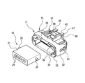
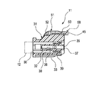
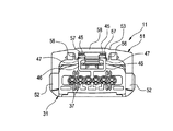
図1は実施形態に係るレバー式コネクタの外観を示すレバー式コネクタの前方側から視た斜視図、図2は実施形態に係るレバー式コネクタの外観を示すレバー式コネクタの後方側から視た斜視図、図3は実施形態に係るレバー式コネクタの構成を示すレバー式コネクタの分解斜視図、図4は実施形態に係るレバー式コネクタの内部構造を示すレバー式コネクタの断面図、図5はレバー式コネクタを構成するコネクタハウジングの構造を説明するコネクタハウジングの後方側から視た斜視図及び一部の拡大斜視図、図6はレバー式コネクタを構成するレバーの構造を説明するレバーの後方側から視た斜視図及び一部の拡大斜視図である。 FIG. 1 is a perspective view of the lever-type connector according to the embodiment as viewed from the front side of the lever-type connector, and FIG. 2 is a perspective view of the lever-type connector according to the embodiment as viewed from the rear side. 3 is an exploded perspective view of the lever-type connector showing the configuration of the lever-type connector according to the embodiment, FIG. 4 is a cross-sectional view of the lever-type connector showing the internal structure of the lever-type connector according to the embodiment, and FIG. FIG. 6 is a perspective view seen from the rear side of the connector housing for explaining the structure of the connector housing constituting the connector, and a partial enlarged perspective view thereof. FIG. 6 is a diagram showing the structure of the lever constituting the lever connector from the rear side of the lever. It is the perspective view which looked, and one part enlarged perspective view.
図1及び図2に示すように、本実施形態に係るレバー式コネクタ11は、被接続部であるレセプタクル12に接続される。
As shown in FIGS. 1 and 2, the
レセプタクル12は、合成樹脂から成形されたハウジング21を備え、このハウジング21には、その内部に、雄端子(図示略)が幅方向に間隔をあけて収容されている。ハウジング21には、レバー式コネクタ11との接続側に嵌合穴22を有するフード部23が形成されている。ハウジング21には、レバー式コネクタ11との接続側と反対側に、複数の挿通孔24が形成されており、これらの挿通孔24には、ハウジング21内に収容された雄端子に接続された電線が通される。また、このレセプタクル12のハウジング21には、フード部23の両側部に、円柱状のガイドボス25が形成されている。
The
図3及び図4に示すように、レバー式コネクタ11は、合成樹脂から成形されたコネクタハウジング(ハウジング)31を有しており、このコネクタハウジング31に、合成樹脂から成形されたレバー51が装着されている。
As shown in FIGS. 3 and 4, the lever-
コネクタハウジング31には、先端側に開口部30が形成されており、この開口部30にレセプタクル12が挿し込まれる。このコネクタハウジング31は、インナハウジング32と、このインナハウジング32の周囲を囲うように一体的に設けられたアウタカバー33とを有しており、これらのインナハウジング32とアウタカバー33とはレセプタクル12との接続側と反対側である後端側で連結されている。
The
インナハウジング32には、幅方向に間隔をあけて複数のキャビティ35が形成されており、これらのキャビティ35には、雌端子(端子)36が収容されている。
A plurality of
図5に示すように、コネクタハウジング31には、後端側に、複数の挿通孔37が形成されており、これらの挿通孔37には、コネクタハウジング31内に収容された雌端子36に接続された電線が通される。
As shown in FIG. 5, the
コネクタハウジング31には、インナハウジング32とアウタカバー33との間に隙間38が形成されており、この隙間38に、レセプタクル12のフード部23が挿し込まれる。
A
また、コネクタハウジング31には、インナハウジング32とアウタカバー33との隙間38の奥に、パッキン39が装着されており、レセプタクル12のフード部23が隙間38へ挿し込まれた際に、フード部23と隙間38との間がパッキン39によってシールされる。
The
コネクタハウジング31には、その両側部に、レバー支持軸41が設けられている。これらのレバー支持軸41は、コネクタハウジング31の外面から突出されたもので、略円柱状に形成されており、その先端部には、それぞれ径方向外方へ向かって互いに反対方向へ突出された爪部41aが形成されている。
The
また、コネクタハウジング31には、その両側部に、開口部30側からスリット43が前後方向に沿ってレバー支持軸41の近傍の中間部まで形成されており、これらのスリット43には、レセプタクル12に形成されたガイドボス25が挿入されてスライドされる。
Further, the
また、コネクタハウジング31の上面側における後端には、レバー当接部45が設けられており、このレバー当接部45に、レバー51の後述する操作部58が当接可能とされている。
A
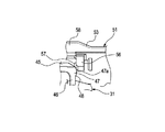
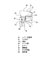
また、コネクタハウジング31には、レバー当接部45が上端に形成された壁部46を有しており、これらの壁部46の外面側に、レバー51の回動方向と交差する外方へ突出するロック山(山部)47が形成されている。
In addition, the
このロック山47には、その頂点47aよりも、後述するレバー51のロック方向である下方側にテーパ面48が形成されている。このテーパ面48は、レバー51のロック方向である下方へ向かって、後述するレバー51のロック突起(突起部)57の突出方向であるコネクタハウジング31の内側へ次第に傾斜されている。
A
図6に示すように、上記のコネクタハウジング31に装着されるレバー51は、互いに間隔あけて配置された板状の一対の支持板部52と、支持板部52の周囲の一部同士を連結する連結部53とを有し、全体として略コ字状に形成されている。
As shown in FIG. 6, the
それぞれの支持板部52には、支点孔54が形成されており、この支点孔54には、互いに対向する位置に凹部54aが形成されている。この支点孔54には、その凹部54aに爪部41aを合わせた状態でレバー支持軸41が挿通される。これにより、レバー51は、支点孔54に挿通されたレバー支持軸41の軸線を中心として回動可能にコネクタハウジング31に装着される。
Each
なお、レバー支持軸41の爪部41aは、支点孔54よりも支持板部52の外面側に配置され、よって、爪部41aが支持板部52の外面側を係止することにより、レバー51が回動される際にレバー51の支点孔54からのレバー支持軸41の抜け出しが防止される。
The
また、レバー51のそれぞれの支持板部52には、その対向面側に、ガイド溝55が形成されている。このガイド溝55は、一端が支点孔54の下方近傍に配置され、他端が、コネクタハウジング31の先端側へ向かって緩やかに湾曲しながら延在されている。このガイド溝55は、その幅寸法がレセプタクル12のガイドボス25の径よりも僅かに大きくされており、これにより、ガイド溝55内には、コネクタハウジング31のスリット43へ挿入されたガイドボス25が収容可能とされている。
Each
このガイド溝55は、他端側が開放されており、この開放された他端部分が挿入口55aとされている。そして、レバー51がコネクタハウジング31の先端側へ回動された状態で、ガイド溝55の挿入口55aがコネクタハウジング31のスリット43と重なる位置に配置され、スリット43に挿入されるレセプタクル12のガイドボス25が挿入口55aからガイド溝55にも挿入される。
The other end of the
また、レバー51の連結部53には、レバー51の回動方向に沿う一対の支持壁56が形成されている。これら支持壁56は、互いに対向する側面に、ロック山47と反対側へそれぞれ突出するロック突起57が形成されている。これらのロック突起57は、コネクタハウジング31のロック山47へ係合可能とされている。
In addition, a pair of
上記のレバー51は、その連結部53が、操作部58とされており、コネクタハウジング31に対して操作部58を把持して回動させることができるようになっている。
The connecting
このレバー51は、その操作部58がコネクタハウジング31の先端側へ配置されてガイド溝55の挿入口55aがスリット43と重なる位置に配置された位置が接続可能位置(図1及び図2に示す位置)とされ、操作部58がコネクタハウジング31の後端側へ配置されてロック突起57がロック山47へ係合された位置が接続ロック位置(図4及び図7に示す位置)とされている。
In the
次に、上記のレバー式コネクタ11をレセプタクル12へ接続する場合について説明する。
Next, the case where the above-mentioned
まず、接続可能位置にレバー51を配置させた状態で、レセプタクル12をレバー式コネクタ11のコネクタハウジング31の開口部30に挿入させる。
First, the
このようにすると、レセプタクル12のフード部23がインナハウジング32に被せられるとともに、レセプタクル12のガイドボス25が、コネクタハウジング31のスリット43へ挿入される。また、このレセプタクル12のガイドボス25は、挿入口55aからガイド溝55にも挿入される。
In this way, the
この状態において、レバー51の操作部58を把持し、操作部58をコネクタハウジング31の後端側であるロック方向へ移動させる。このようにすると、レバー51がレバー支持軸41を中心として回動される。すると、ガイド溝55がスリット43と重なる位置がレバー支持軸41に向かって移動され、これにより、スリット43及びガイド溝55の両方に挿入されているレセプタクル12のガイドボス25が、コネクタハウジング31の長手方向に沿ってレバー支持軸41側であるコネクタハウジング31の後端側へ移動される。これにともない、レセプタクル12がレバー式コネクタ11へ引き込まれる。
In this state, the operating
図7に示すように、レバー51の操作部58を接続ロック位置まで移動させると、レセプタクル12の嵌合穴22にインナハウジング32が嵌合されてフード部23が隙間38へ挿し込まれ、よって、インナハウジング32の雌端子36とレセプタクル12の雄端子とが接続されて電線同士が導通される。また、レセプタクル12のフード部23と隙間38との間がパッキン39によってシールされ、雌端子36と雄端子との接続箇所がシールされる。
As shown in FIG. 7, when the
また、図8及び図9に示すように、レバー51の操作部58を接続ロック位置へ移動させると、レバー51のロック突起57が、コネクタハウジング31側のロック山47に当接する。
As shown in FIGS. 8 and 9, when the operating
この状態からレバー51を、ロック方向へさらに回動させることにより、図10に示すように、ロック突起57の中心がロック山47の頂点47aを超えてロック方向へ移動すると、ロック突起57がロック山47に係合し、よって、レバー51がコネクタハウジング31にロックされた状態となる。これにより、レバー式コネクタ11は、レセプタクル12に確実に接続された状態に維持される。
By further rotating the
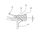
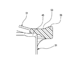
また、ロック突起57がロック山47の頂点47aを超えてロック方向側へ移動すると、図11に示すように、ロック突起57がロック山47のテーパ面48に押し付けられる。これにより、ロック突起57には、テーパ面48への押し付け力FAが分散し、その分力FBが、レバー51をロック方向へさらに回動させる回動力として作用する。したがって、レバー51は、さらにロック方向へ回動され、これにより、このレバー51の操作部58がコネクタハウジング31のレバー当接部45に押し付けられた状態に当接する。
Further, when the
つまり、レバー51の操作部58は、ロック突起57のロック山47への係合開始時では、図12に示すように、レバー当接部45に対してクリアランスCを有しているが、ロック突起57がロック山47の頂点47aを超えてロック方向へ移動すると、ロック突起57がテーパ面48に当接して摺動し、テーパ面48で係合することにより、図13に示すように、クリアランスCがなくレバー当接部45に押し付けられることとなる。
That is, the
上記のようにレセプタクル12へ接続したレバー式コネクタ11の接続を解除するには、ロック状態のレバー51の操作部58を把持し、このレバー51をコネクタハウジング31の先端側へ移動させる。このようにすると、レバー51は、そのロック突起57がロック山47から外れてロックが解除される。
To release the connection of the lever-
さらに、レバー支持軸41を中心としてコネクタハウジング31の前方側であるアンロック方向へレバー51を回動させると、ガイド溝55がスリット43と重なる位置がレバー支持軸41から離間する方向へ移動され、これにより、スリット43及びガイド溝55の両方に挿入されているレセプタクル12のガイドボス25が、コネクタハウジング31の長手方向に沿ってレバー支持軸41と反対側であるコネクタハウジング31の先端側へ移動される。これにともない、レセプタクル12がレバー式コネクタ11から引き抜かれ、インナハウジング32の雌端子36とレセプタクル12の雄端子との接続が解除される。
Further, when the
このように、上記実施形態に係るレバー式コネクタによれば、レバー51のロック突起57が、コネクタハウジング31のロック山47のテーパ面48に沿って摺動し、常にテーパ面48上に配置されてテーパ面48で係合することにより、レバー51にロック方向への回動力が付与され続ける。これにより、レバー51の連結部53からなる操作部58がコネクタハウジング31のレバー当接部45に当接され、レバー51をコネクタハウジング31へロックさせた状態でレバー51の操作部58とコネクタハウジング31のレバー当接部45との間のクリアランスCをなくすことができる。
Thus, according to the lever-type connector according to the above embodiment, the
したがって、自動車等の車両のワイヤハーネスの接続用として用いたとしても、車両の走行時等の振動や熱ストレスによるレバー51のガタつきを防止することができ、ガタつきによるロック突起57とロック山47とからなるロック部分の摩耗・損傷を抑え、端子同士の良好な接続状態を維持させることができる。
Therefore, even when used for connecting a wire harness of a vehicle such as an automobile, rattling of the
つまり、ガタつきを防ぐために高価なスプリングを用いたものと比較して、低コストで接続信頼性を高めることができる。 In other words, the connection reliability can be increased at a lower cost than that using an expensive spring to prevent rattling.
また、ロック山47とロック突起57とからなるロック部分が、レバー51の回動軸となるレバー支持軸41から離れた位置に配置されているので、振動が作用した際のレバー51の動きをより良好に抑えることができる。
In addition, since the lock portion composed of the
なお、ロック山47のテーパ面48に窪みを設け、この窪みにロック突起57を係合させても良い。このように、窪みにロック突起57を係合させれば、振動の作用時におけるレバー51のガタつきを、さらに良好に抑えることができる。
It should be noted that a recess may be provided in the tapered
なお、本発明は、上述した実施形態に限定されるものではなく、適宜、変形、改良、等が可能である。その他、上述した実施形態における各構成要素の材質、形状、寸法、数、配置箇所、等は本発明の目的を達成できるものであれば任意であり、限定されない。 In addition, this invention is not limited to embodiment mentioned above, A deformation | transformation, improvement, etc. are possible suitably. In addition, the material, shape, dimensions, number, location, and the like of each component in the above-described embodiment are arbitrary and are not limited as long as the object of the present invention can be achieved.
11 レバー式コネクタ
12 レセプタクル(被接続部)
31 コネクタハウジング(ハウジング)
36 雌端子(端子)
47 ロック山(山部)
47a 頂点
48 テーパ面
51 レバー
52 支持板部
53 連結部
57 ロック突起(突起部)
11
31 Connector housing (housing)
36 Female terminal (terminal)
47 Rock Mountain (Mountain)
Claims (1)
前記レバーは、前記ハウジングの両側面に回動可能に支持された支持板部と、これらの支持板部同士を連結する連結部とを備え、
前記ハウジングには、前記レバーの回動方向と交差する方向へ突出する山部が形成され、
前記レバーには、前記山部と反対側へ突出し、前記レバーの前記接続ロック位置への回動によって前記山部に係合する突起部が形成され、
前記山部は、その頂点よりも前記レバーの前記ロック方向側に、前記ロック方向へ向かって次第に前記突起部の突出方向へ傾斜するテーパ面を有し、
前記レバーは、前記突起部が前記山部の頂点を超えて前記テーパ面に沿って摺動し、常にテーパ面上に配置されて前記テーパ面で係合することにより、前記ロック方向への回動力が付与され、前記連結部が前記ハウジングに当接されることを特徴とするレバー式コネクタ。 A housing connected to the connected portion; and the housing is rotatably provided, and is rotated in a locking direction, which is one direction, and arranged at a connection lock position, thereby connecting the connected portion and the housing. A lever-type connector provided with a lever that draws each other and connects terminals to be connected and terminals provided in the housing;
The lever includes a support plate portion that is rotatably supported on both side surfaces of the housing, and a connecting portion that connects these support plate portions.
The housing is formed with a peak portion protruding in a direction intersecting the rotation direction of the lever,
The lever is formed with a protrusion that protrudes to the opposite side of the peak and engages with the peak by turning the lever to the connection lock position.
The peak portion has a tapered surface that is gradually inclined toward the protruding direction of the protruding portion toward the locking direction on the locking direction side of the lever from the apex thereof,
The lever slides along the tapered surface beyond the peak of the peak , and is always disposed on the tapered surface and engaged with the tapered surface, whereby the lever rotates in the locking direction. A lever-type connector, wherein power is applied and the connecting portion is brought into contact with the housing.
Priority Applications (6)
| Application Number | Priority Date | Filing Date | Title |
|---|---|---|---|
| JP2010233821A JP5679552B2 (en) | 2010-10-18 | 2010-10-18 | Lever type connector |
| CN201180050313.2A CN103168399B (en) | 2010-10-18 | 2011-10-04 | lever connector |
| PCT/JP2011/072895 WO2012053350A1 (en) | 2010-10-18 | 2011-10-04 | Lever connector |
| BR112013009399A BR112013009399A2 (en) | 2010-10-18 | 2011-10-04 | lever connector |
| RU2013122804/07A RU2531509C1 (en) | 2010-10-18 | 2011-10-04 | Lever type connector |
| US13/865,028 US9209562B2 (en) | 2010-10-18 | 2013-04-17 | Lever connector |
Applications Claiming Priority (1)
| Application Number | Priority Date | Filing Date | Title |
|---|---|---|---|
| JP2010233821A JP5679552B2 (en) | 2010-10-18 | 2010-10-18 | Lever type connector |
Publications (2)
| Publication Number | Publication Date |
|---|---|
| JP2012089302A JP2012089302A (en) | 2012-05-10 |
| JP5679552B2 true JP5679552B2 (en) | 2015-03-04 |
Family
ID=45975069
Family Applications (1)
| Application Number | Title | Priority Date | Filing Date |
|---|---|---|---|
| JP2010233821A Expired - Fee Related JP5679552B2 (en) | 2010-10-18 | 2010-10-18 | Lever type connector |
Country Status (6)
| Country | Link |
|---|---|
| US (1) | US9209562B2 (en) |
| JP (1) | JP5679552B2 (en) |
| CN (1) | CN103168399B (en) |
| BR (1) | BR112013009399A2 (en) |
| RU (1) | RU2531509C1 (en) |
| WO (1) | WO2012053350A1 (en) |
Families Citing this family (3)
| Publication number | Priority date | Publication date | Assignee | Title |
|---|---|---|---|---|
| JP6424190B2 (en) * | 2016-09-07 | 2018-11-14 | 矢崎総業株式会社 | Lever type connector |
| JP6564750B2 (en) * | 2016-09-07 | 2019-08-21 | 矢崎総業株式会社 | Lever type connector |
| JP6874015B2 (en) * | 2016-09-29 | 2021-05-19 | タイコエレクトロニクスジャパン合同会社 | Connector assembly |
Family Cites Families (16)
| Publication number | Priority date | Publication date | Assignee | Title |
|---|---|---|---|---|
| JP2971531B2 (en) * | 1990-06-29 | 1999-11-08 | 住友電装株式会社 | Connector connection structure |
| JP3002940B2 (en) * | 1994-02-18 | 2000-01-24 | 矢崎総業株式会社 | Lever connector |
| JPH08213102A (en) * | 1995-02-02 | 1996-08-20 | Amp Japan Ltd | Lever connector |
| EP1079473B1 (en) * | 1995-10-24 | 2003-03-12 | Sumitomo Wiring Systems, Ltd. | Lever type connector |
| JP3152155B2 (en) * | 1996-10-03 | 2001-04-03 | 住友電装株式会社 | Lever connector |
| JP3436181B2 (en) * | 1999-04-19 | 2003-08-11 | 住友電装株式会社 | Lever connector |
| JP2003036927A (en) * | 2001-07-25 | 2003-02-07 | Yazaki Corp | Lever type connector |
| JP3911142B2 (en) * | 2001-09-19 | 2007-05-09 | 矢崎総業株式会社 | Lever fitting type connector |
| JP2003297481A (en) | 2002-04-01 | 2003-10-17 | Sumitomo Wiring Syst Ltd | Lever type connector |
| RU2266593C1 (en) * | 2004-05-27 | 2005-12-20 | Донецкий Юрий Игоревич | Plug connector |
| US7090518B1 (en) * | 2005-05-17 | 2006-08-15 | J.S.T. Corporation | Electrical connector with a locking mechanism |
| RU2295182C1 (en) * | 2005-07-29 | 2007-03-10 | Юрий Игоревич Донецкий | Plug connector |
| JP4598681B2 (en) | 2006-01-17 | 2010-12-15 | 矢崎総業株式会社 | Lever fitting type connector |
| JP4830920B2 (en) | 2007-03-09 | 2011-12-07 | 住友電装株式会社 | Lever type connector |
| RU2343607C1 (en) * | 2007-08-17 | 2009-01-10 | Юрий Игоревич Донецкий | Plug and socket joint |
| JP5080313B2 (en) * | 2007-11-09 | 2012-11-21 | 矢崎総業株式会社 | Lever fitting type connector |
-
2010
- 2010-10-18 JP JP2010233821A patent/JP5679552B2/en not_active Expired - Fee Related
-
2011
- 2011-10-04 CN CN201180050313.2A patent/CN103168399B/en not_active Expired - Fee Related
- 2011-10-04 BR BR112013009399A patent/BR112013009399A2/en not_active Application Discontinuation
- 2011-10-04 WO PCT/JP2011/072895 patent/WO2012053350A1/en not_active Ceased
- 2011-10-04 RU RU2013122804/07A patent/RU2531509C1/en not_active IP Right Cessation
-
2013
- 2013-04-17 US US13/865,028 patent/US9209562B2/en not_active Expired - Fee Related
Also Published As
| Publication number | Publication date |
|---|---|
| CN103168399A (en) | 2013-06-19 |
| US9209562B2 (en) | 2015-12-08 |
| US20130230994A1 (en) | 2013-09-05 |
| JP2012089302A (en) | 2012-05-10 |
| CN103168399B (en) | 2015-11-25 |
| RU2531509C1 (en) | 2014-10-20 |
| WO2012053350A1 (en) | 2012-04-26 |
| BR112013009399A2 (en) | 2016-07-26 |
Similar Documents
| Publication | Publication Date | Title |
|---|---|---|
| JP6755148B2 (en) | Lever type connector | |
| JP6492030B2 (en) | connector | |
| EP2276123A1 (en) | Lever type connector | |
| JP5588773B2 (en) | Wire cover, electrical connector | |
| JP2003036927A (en) | Lever type connector | |
| JP5722565B2 (en) | Wire cover, wiring method, electrical connector | |
| CN107453140A (en) | Connector | |
| JP5622316B2 (en) | Lever type connector | |
| JP2001237026A (en) | Connector with lever | |
| JP6618509B2 (en) | Lever type connector | |
| JP3337008B2 (en) | connector | |
| JP5679552B2 (en) | Lever type connector | |
| JP5370862B2 (en) | connector | |
| JP5606089B2 (en) | connector | |
| JP6916040B2 (en) | Lever type connector | |
| CN117941186A (en) | Connectors and connector components | |
| JP2011081951A (en) | Lever-fit type connector | |
| JP5180553B2 (en) | connector | |
| JP2020170633A (en) | Connector housing and electric wire with connector housing | |
| JP6892328B2 (en) | Lever type connector | |
| JP5056379B2 (en) | connector | |
| JP2010062077A (en) | Lever fit-in connector | |
| JP6101495B2 (en) | Connector with lever | |
| JP6931297B2 (en) | Lever type connector | |
| WO2025187377A1 (en) | Connector |
Legal Events
| Date | Code | Title | Description |
|---|---|---|---|
| A621 | Written request for application examination |
Free format text: JAPANESE INTERMEDIATE CODE: A621 Effective date: 20130918 |
|
| A131 | Notification of reasons for refusal |
Free format text: JAPANESE INTERMEDIATE CODE: A131 Effective date: 20140819 |
|
| A521 | Request for written amendment filed |
Free format text: JAPANESE INTERMEDIATE CODE: A523 Effective date: 20141009 |
|
| TRDD | Decision of grant or rejection written | ||
| A01 | Written decision to grant a patent or to grant a registration (utility model) |
Free format text: JAPANESE INTERMEDIATE CODE: A01 Effective date: 20141209 |
|
| A61 | First payment of annual fees (during grant procedure) |
Free format text: JAPANESE INTERMEDIATE CODE: A61 Effective date: 20150105 |
|
| R150 | Certificate of patent or registration of utility model |
Ref document number: 5679552 Country of ref document: JP Free format text: JAPANESE INTERMEDIATE CODE: R150 |
|
| RD02 | Notification of acceptance of power of attorney |
Free format text: JAPANESE INTERMEDIATE CODE: A7422 Effective date: 20150122 |
|
| R250 | Receipt of annual fees |
Free format text: JAPANESE INTERMEDIATE CODE: R250 |
|
| R250 | Receipt of annual fees |
Free format text: JAPANESE INTERMEDIATE CODE: R250 |
|
| R250 | Receipt of annual fees |
Free format text: JAPANESE INTERMEDIATE CODE: R250 |
|
| LAPS | Cancellation because of no payment of annual fees |