JP5678997B2 - Zoom lens system - Google Patents
Zoom lens system Download PDFInfo
- Publication number
- JP5678997B2 JP5678997B2 JP2013136070A JP2013136070A JP5678997B2 JP 5678997 B2 JP5678997 B2 JP 5678997B2 JP 2013136070 A JP2013136070 A JP 2013136070A JP 2013136070 A JP2013136070 A JP 2013136070A JP 5678997 B2 JP5678997 B2 JP 5678997B2
- Authority
- JP
- Japan
- Prior art keywords
- lens
- focal length
- lens group
- positive
- negative
- Prior art date
- Legal status (The legal status is an assumption and is not a legal conclusion. Google has not performed a legal analysis and makes no representation as to the accuracy of the status listed.)
- Active
Links
- 230000014509 gene expression Effects 0.000 claims description 43
- 230000004075 alteration Effects 0.000 description 100
- 238000010586 diagram Methods 0.000 description 85
- 230000003287 optical effect Effects 0.000 description 20
- 206010010071 Coma Diseases 0.000 description 14
- 230000005499 meniscus Effects 0.000 description 9
- 201000009310 astigmatism Diseases 0.000 description 5
- 230000008901 benefit Effects 0.000 description 4
- 230000007246 mechanism Effects 0.000 description 4
- 230000009467 reduction Effects 0.000 description 2
- 230000007423 decrease Effects 0.000 description 1
- 230000004907 flux Effects 0.000 description 1
- 238000004519 manufacturing process Methods 0.000 description 1
- 230000002093 peripheral effect Effects 0.000 description 1
Images


Classifications
-
- G—PHYSICS
- G02—OPTICS
- G02B—OPTICAL ELEMENTS, SYSTEMS OR APPARATUS
- G02B15/00—Optical objectives with means for varying the magnification
- G02B15/14—Optical objectives with means for varying the magnification by axial movement of one or more lenses or groups of lenses relative to the image plane for continuously varying the equivalent focal length of the objective
- G02B15/16—Optical objectives with means for varying the magnification by axial movement of one or more lenses or groups of lenses relative to the image plane for continuously varying the equivalent focal length of the objective with interdependent non-linearly related movements between one lens or lens group, and another lens or lens group
- G02B15/20—Optical objectives with means for varying the magnification by axial movement of one or more lenses or groups of lenses relative to the image plane for continuously varying the equivalent focal length of the objective with interdependent non-linearly related movements between one lens or lens group, and another lens or lens group having an additional movable lens or lens group for varying the objective focal length
-
- G—PHYSICS
- G02—OPTICS
- G02B—OPTICAL ELEMENTS, SYSTEMS OR APPARATUS
- G02B13/00—Optical objectives specially designed for the purposes specified below
- G02B13/18—Optical objectives specially designed for the purposes specified below with lenses having one or more non-spherical faces, e.g. for reducing geometrical aberration
-
- G—PHYSICS
- G02—OPTICS
- G02B—OPTICAL ELEMENTS, SYSTEMS OR APPARATUS
- G02B15/00—Optical objectives with means for varying the magnification
- G02B15/14—Optical objectives with means for varying the magnification by axial movement of one or more lenses or groups of lenses relative to the image plane for continuously varying the equivalent focal length of the objective
- G02B15/143—Optical objectives with means for varying the magnification by axial movement of one or more lenses or groups of lenses relative to the image plane for continuously varying the equivalent focal length of the objective having three groups only
- G02B15/1435—Optical objectives with means for varying the magnification by axial movement of one or more lenses or groups of lenses relative to the image plane for continuously varying the equivalent focal length of the objective having three groups only the first group being negative
- G02B15/143507—Optical objectives with means for varying the magnification by axial movement of one or more lenses or groups of lenses relative to the image plane for continuously varying the equivalent focal length of the objective having three groups only the first group being negative arranged -++
-
- G—PHYSICS
- G02—OPTICS
- G02B—OPTICAL ELEMENTS, SYSTEMS OR APPARATUS
- G02B27/00—Optical systems or apparatus not provided for by any of the groups G02B1/00 - G02B26/00, G02B30/00
- G02B27/0025—Optical systems or apparatus not provided for by any of the groups G02B1/00 - G02B26/00, G02B30/00 for optical correction, e.g. distorsion, aberration
Description
本発明は、標準域から中望遠領域までを含むズームレンズ系に関する。 The present invention relates to a zoom lens system including a standard range to a medium telephoto range.
従来、標準域から中望遠領域までを含むズームレンズ系として、負正負正の4群ズームレンズ系や負正の2群ズームレンズ系が用いられている。一般的に、負正負正の4群ズームレンズ系は、設計自由度が高く収差補正に有利という長所を持つ反面、レンズ群(レンズ枚数)が多いためメカ機構が大型かつ複雑になるという短所を持っており、負正の2群ズームレンズ系は、レンズ群(レンズ枚数)が少ないためメカ機構がシンプルでコストを抑えやすいという長所を持つ反面、設計自由度が低く収差補正に不利という短所を持っている。また、F値の小さい明るいズームレンズ系を得ようとする場合、負正の2群ズームレンズ系では設計自由度の低さから収差補正(特にコマフレアの補正)が難しく光学性能が劣化しやすいため、設計自由度の高い負正負正の4群ズームレンズ系がよく用いられている。 Conventionally, as a zoom lens system including a standard range to a middle telephoto range, a negative positive / negative positive four-group zoom lens system and a negative positive two-group zoom lens system are used. In general, the negative / positive / negative four-group zoom lens system has the advantage that it has a high degree of freedom in design and is advantageous for aberration correction, but has the disadvantage that the mechanical mechanism becomes large and complicated due to the large number of lens groups (number of lenses) The negative and positive two-group zoom lens system has the advantage that the mechanical mechanism is simple and the cost is easy to control because the number of lens groups (number of lenses) is small, but it has the disadvantage of low design freedom and disadvantageous aberration correction. have. Also, when trying to obtain a bright zoom lens system with a small F value, aberration correction (particularly coma flare correction) is difficult and optical performance tends to deteriorate due to the low degree of freedom of design in a negative-positive two-group zoom lens system. A negative, positive and negative four-group zoom lens system having a high degree of design freedom is often used.
特許文献1〜3には、負正の2群ズームレンズ系が開示されている。しかし、いずれも、F値が3.5〜4程度しかなく明るさが不十分であり、また、コマ収差、球面収差、非点収差、歪曲収差、色収差などの諸収差が大きく発生して光学性能が劣化してしまうという問題がある。特許文献1は、フレアカット絞りを設けてこれをズーミング時に移動させることにより光量確保を狙っているが、そもそものレンズ全系の収差補正が不十分であるため、コマ収差の補正にフレアカット絞りが効果的に機能していない。
本発明は、以上の問題意識に基づいてなされたものであり、負正の2群ズームレンズ系において、メカ機構がシンプルでコストを抑えやすいという長所を生かしつつ、F値の小さい十分な明るさを得るとともに、コマ収差、球面収差、非点収差、歪曲収差、色収差などの諸収差を良好に補正して優れた光学性能を達成することを目的とする。 The present invention has been made on the basis of the above problem awareness, and in a negative-positive two-group zoom lens system, sufficient brightness with a small F value is obtained while taking advantage of the simple mechanical mechanism and easy cost reduction. The objective is to achieve excellent optical performance by satisfactorily correcting various aberrations such as coma, spherical aberration, astigmatism, distortion, and chromatic aberration.
本発明のズームレンズ系は、物体側から順に、負の屈折力の第1レンズ群と、正の屈折力の第2レンズ群とからなり、短焦点距離端から長焦点距離端への変倍に際し、第1レンズ群と第2レンズ群の間隔が減少するズームレンズ系において、第2レンズ群は、物体側から順に、正の屈折力の第2Aレンズ群と、開口絞りと、正の屈折力の第2Bレンズ群とからなり、第2Aレンズ群は、1枚または2枚の正レンズと、正レンズと負レンズの接合レンズとからなり、次の条件式(1)を満足することを特徴としている。
(1)0.65<f2A/f2B<1.0
但し、
f2A:第2Aレンズ群の焦点距離、
f2B:第2Bレンズ群の焦点距離、
である。
The zoom lens system according to the present invention includes, in order from the object side, a first lens unit having a negative refractive power and a second lens group having a positive refractive power, and zooming from a short focal length end to a long focal length end. At this time, in the zoom lens system in which the distance between the first lens group and the second lens group is reduced, the second lens group includes, in order from the object side, the second A lens group having a positive refractive power, an aperture stop, and positive refraction. The second A lens group is composed of one or two positive lenses and a cemented lens of a positive lens and a negative lens, and satisfies the following conditional expression (1): It is a feature.
(1) 0.65 <f2A / f2B <1.0
However,
f2A: focal length of the 2A lens group,
f2B: focal length of the second B lens group,
It is.
本発明のズームレンズ系は、次の条件式(2)を満足することが好ましい。
(2)0.5<FP/RP<1.5
但し、
FP:短焦点距離端における開口絞りより物体側のレンズ群の焦点距離(短焦点距離端における第1レンズ群と第2Aレンズ群の合成焦点距離)、
RP:短焦点距離端における開口絞りより像側のレンズ群の焦点距離(短焦点距離端における第2Bレンズ群の焦点距離)、
である。
The zoom lens system according to the present invention preferably satisfies the following conditional expression (2).
(2) 0.5 <FP / RP <1.5
However,
FP: focal length of the lens unit closer to the object side than the aperture stop at the short focal length end (combined focal length of the first lens group and the second A lens group at the short focal length end),
RP: focal length of the lens group on the image side from the aperture stop at the short focal length end (focal length of the second B lens group at the short focal length end),
It is.
条件式(2)が規定する条件範囲の中でも、次の条件式(2’)を満足することが好ましい。
(2’)1.0<FP/RP<1.4
Among the condition ranges defined by the conditional expression (2), it is preferable that the following conditional expression (2 ′) is satisfied.
(2 ′) 1.0 <FP / RP <1.4
第2Bレンズ群は、1枚または2枚の正レンズと、1枚の負レンズとから構成することができる。 The second B lens group can be composed of one or two positive lenses and one negative lens.
本発明のズームレンズ系は、第1レンズ群が、非球面レンズを有しており、次の条件式(3)を満足することが好ましい。
(3)1.6<fasp/f1<5.0
但し、
fasp:第1レンズ群中の非球面レンズの焦点距離、
f1:第1レンズ群の焦点距離、
である。
In the zoom lens system of the present invention, it is preferable that the first lens group has an aspheric lens, and the following conditional expression (3) is satisfied.
(3) 1.6 <fasp / f1 <5.0
However,
fasp: focal length of the aspherical lens in the first lens group,
f1: the focal length of the first lens group,
It is.
本発明のズームレンズ系は、次の条件式(4)を満足することが好ましい。
(4)Aνd>52.5
但し、
Aνd:第1レンズ群中の非球面レンズのd線に対するアッベ数、
である。
The zoom lens system according to the present invention preferably satisfies the following conditional expression (4).
(4) Aνd> 52.5
However,
Aνd: Abbe number of the aspherical lens in the first lens group with respect to the d-line,
It is.
本発明のズームレンズ系は、次の条件式(5)を満足することが好ましい。
(5)−0.92<f1/f2<−0.8
但し、
f1:第1レンズ群の焦点距離、
f2:第2レンズ群の焦点距離、
である。
The zoom lens system according to the present invention preferably satisfies the following conditional expression (5).
(5) -0.92 <f1 / f2 <-0.8
However,
f1: the focal length of the first lens group,
f2: focal length of the second lens group,
It is.
本発明によれば、負正の2群ズームレンズ系において、メカ機構がシンプルでコストを抑えやすいという長所を生かしつつ、F値の小さい十分な明るさを得るとともに、コマ収差、球面収差、非点収差、歪曲収差、色収差などの諸収差を良好に補正して優れた光学性能を達成することができる。 According to the present invention, in the negative and positive two-group zoom lens system, while taking advantage of the simple mechanical mechanism and easy cost reduction, it is possible to obtain a sufficient brightness with a small F-number, as well as coma aberration, spherical aberration, Excellent optical performance can be achieved by satisfactorily correcting various aberrations such as point aberration, distortion, and chromatic aberration.
本実施形態のズームレンズ系は、全数値実施例1−7を通じて、図43の簡易移動図に示すように、物体側から順に、負の屈折力の第1レンズ群G1と、正の屈折力の第2レンズ群G2とからなる。第2レンズ群G2は、物体側から順に、正の屈折力の第2Aレンズ群G2Aと、開口絞りSと、正の屈折力の第2Bレンズ群G2Bとからなる。Iは像面である。 The zoom lens system according to the present embodiment includes, in order from the object side, the first lens unit G1 having a negative refractive power and the positive refractive power in order from the object side, as shown in the simplified movement diagram of FIG. The second lens group G2. The second lens group G2 includes, in order from the object side, a second A lens group G2A having a positive refractive power, an aperture stop S, and a second B lens group G2B having a positive refractive power. I is the image plane.
本実施形態のズームレンズ系は、全数値実施例1−7を通じて、図43の簡易移動図に示すように、短焦点距離端(Wide)から長焦点距離端(Tele)への変倍に際し、第1レンズ群G1が一旦像側に移動した後に物体側に移動し(Uターンし)、第2レンズ群G2(第2Aレンズ群G2A、開口絞りS、第2Bレンズ群G2B)が単調に物体側に移動し、その結果、第1レンズ群G1と第2レンズ群G2の間隔が減少する。なお、無限遠物体から有限距離物体へのフォーカシングは、第1レンズ群G1を物体側に移動させる(繰り出す)ことによって行う。 The zoom lens system according to the present embodiment, as shown in the simplified movement diagram of FIG. 43, through all numerical examples 1-7, upon zooming from the short focal length end (Wide) to the long focal length end (Tele), The first lens group G1 once moves to the image side and then moves to the object side (U-turn), and the second lens group G2 (second A lens group G2A, aperture stop S, second B lens group G2B) monotonously As a result, the distance between the first lens group G1 and the second lens group G2 decreases. Note that focusing from an infinitely distant object to a finite distance object is performed by moving (feeding out) the first lens group G1 toward the object side.
第1レンズ群G1は、全数値実施例1−7を通じて、物体側から順に、負レンズ11と、負レンズ12と、正レンズ13とからなる。負レンズ12は、その像側の面が非球面からなる。
The first lens group G1 includes a
第2Aレンズ群G2Aは、数値実施例1、2、4では、物体側から順に、正レンズ21と、物体側から順に位置する正レンズ22と負レンズ23の接合レンズとからなる。
第2Aレンズ群G2Aは、数値実施例3、5−7では、物体側から順に、正レンズ21’と、正レンズ22’と、物体側から順に位置する正レンズ23’と負レンズ24’の接合レンズとからなる。
In Numerical Examples 1, 2, and 4, the second A lens group G2A includes a
In Numerical Examples 3 and 5-7, the second A lens group G2A includes, in order from the object side, a
第2Bレンズ群G2Bは、数値実施例1−6では、物体側から順に、正レンズ25と、負レンズ26と、正レンズ27とからなる。
第2Bレンズ群G2Bは、数値実施例7では、物体側から順に、負レンズ25’と、正レンズ26’とからなる。
In Numerical Example 1-6, the second B lens group G2B includes a
In Numerical Example 7, the second B lens group G2B includes a
従来の一般的な負正の2群ズームレンズ系は、正の屈折力の第2レンズ群をトリプレットの前側凸と凹の間に凸メニスカスレンズを挿入したいわゆるエルノスター構成としたものが多く採用されているが、収差補正、特にコマフレアの補正が困難であり、光学性能が劣化しやすいという問題がある。 Many conventional negative-positive two-group zoom lens systems have a so-called Elnostar configuration in which a second lens unit having a positive refractive power is inserted with a convex meniscus lens between the front convex and concave of the triplet. However, it is difficult to correct aberrations, particularly coma flare, and there is a problem that optical performance tends to deteriorate.
そこで本実施形態のズームレンズ系は、第2レンズ群G2を、開口絞りSを境にして、それより物体側の第2Aレンズ群G2Aと像側の第2Bレンズ群G2Bとに分け、主として第2Aレンズ群G2Aによって結像を行い、主として第2Bレンズ群G2Bによってコマフレアを良好に補正することで、優れた光学性能を達成している。 Therefore, in the zoom lens system of the present embodiment, the second lens group G2 is divided into the second A lens group G2A on the object side and the second B lens group G2B on the image side with the aperture stop S as a boundary, and mainly the second lens group G2. An image is formed by the 2A lens group G2A, and coma flare is corrected favorably mainly by the second B lens group G2B, thereby achieving excellent optical performance.
さらに本実施形態のズームレンズ系は、第2レンズ群G2(第2Aレンズ群G2A、第2Bレンズ群G2B)のレンズ構成を工夫し、且つ、第2Aレンズ群G2Aと第2Bレンズ群G2Bのパワーバランスを最適設定することで、F値の小さい十分な明るさを得るとともに、コマ収差、球面収差、非点収差、歪曲収差、色収差などの諸収差を良好に補正して優れた光学性能を達成している。 Furthermore, in the zoom lens system of the present embodiment, the lens configuration of the second lens group G2 (the second A lens group G2A and the second B lens group G2B) is devised, and the power of the second A lens group G2A and the second B lens group G2B is devised. By optimally setting the balance, sufficient brightness with a small F-number is obtained, and various optical aberrations such as coma, spherical aberration, astigmatism, distortion, and chromatic aberration are well corrected to achieve excellent optical performance. doing.
第2Aレンズ群G2Aは、全数値実施例1−7を通じて、1枚または2枚の正レンズ(正レンズ21、または正レンズ21’と正レンズ22’)と、正レンズと負レンズの接合レンズ(正レンズ22と負レンズ23の接合レンズ、または正レンズ23’と負レンズ24’の接合レンズ)とからなる。
第2Bレンズ群G2Bは、全数値実施例1−7を通じて、1枚または2枚の正レンズ(正レンズ25と正レンズ27、または正レンズ26’)と、1枚の負レンズ(負レンズ26または負レンズ25’)とからなる。
第2Bレンズ群G2B中に、負の球面収差を発生させる負レンズ(負レンズ26または負レンズ25’)を設けることで、F値の小さい十分な明るさを得たときであっても、球面収差を良好に補正することができる。
また、第2Aレンズ群G2A中の開口絞りSの直前位置に、正レンズと負レンズの接合レンズ(正レンズ22と負レンズ23の接合レンズ、または正レンズ23’と負レンズ24’の接合レンズ)を設けることで、色収差を良好に補正することができる。
The second A lens group G2A includes one or two positive lenses (a
The second B lens group G2B includes one or two positive lenses (
Even when a sufficient brightness with a small F-number is obtained by providing a negative lens (
In addition, a cemented lens of a positive lens and a negative lens (a cemented lens of the
第1レンズ群G1は、歪曲収差を抑えつつ負の屈折力を得るために、少なくとも1枚の正レンズ(本実施形態では正レンズ13)を含む複数枚のレンズから構成されている。
歪曲収差をより効果的に補正するためには、第1レンズ群G1の最も物体側に正レンズを配置するのが良い。
しかし、F値が大きく明るさが不十分な従来品のズームレンズ系でさえ、最も物体側に配置する正レンズの最大径が大きすぎるため、該正レンズひいてはレンズ全系を小径化しつつ、F値の小さい十分な明るさを得るのは、極めて困難な技術課題である。
この技術課題を解決するために、本実施形態のズームレンズ系は、第1レンズ群G1中に非球面レンズ(本実施形態では負レンズ12)を配置している。この非球面レンズによって、歪曲収差を良好に補正することができ、さらに非球面の光学素材の選択を増やすことで、第1レンズ群G1内のパワー配置をより適切にし、色収差などの諸収差を効果的に補正することができる。
第1レンズ群G1は、無限遠物体から近距離物体へのフォーカシングに際して物体側に移動するフォーカスレンズ群である。第1レンズ群G1に少なくとも1枚の正レンズ(本実施形態では正レンズ13)を含ませることで、フォーカシングに際して、球面収差、歪曲収差、コマ収差が大きく変動するのを抑えることができる。
The first lens group G1 includes a plurality of lenses including at least one positive lens (in the present embodiment, the positive lens 13) in order to obtain negative refractive power while suppressing distortion.
In order to correct distortion more effectively, it is preferable to dispose a positive lens closest to the object side of the first lens group G1.
However, even in a conventional zoom lens system having a large F value and insufficient brightness, the maximum diameter of the positive lens disposed closest to the object side is too large, and therefore the diameter of the positive lens, and thus the entire lens system, is reduced. Obtaining sufficient brightness with a small value is a very difficult technical problem.
In order to solve this technical problem, in the zoom lens system according to the present embodiment, an aspheric lens (in this embodiment, the negative lens 12) is disposed in the first lens group G1. With this aspheric lens, distortion can be corrected well, and by increasing the selection of aspherical optical materials, the power arrangement in the first lens group G1 can be made more appropriate, and various aberrations such as chromatic aberration can be reduced. It can be corrected effectively.
The first lens group G1 is a focus lens group that moves to the object side during focusing from an object at infinity to a near object. By including at least one positive lens (the
条件式(1)は、第2Aレンズ群G2Aの焦点距離と、第2Bレンズ群G2Bの焦点距離との比を規定している。条件式(1)を満足することで、コマ収差や球面収差を良好に補正して、優れた光学性能を達成することができる。
条件式(1)の上限を超えると、開口絞りSの前で光線を強く曲げることになり、コマ収差の補正が不十分になる。
条件式(1)の下限を超えると、開口絞りSより像側の第2Bレンズ群G2Bの正のパワーが弱くなりすぎて、球面収差の補正が不十分になる。
Conditional expression (1) defines the ratio between the focal length of the second A lens group G2A and the focal length of the second B lens group G2B. Satisfying conditional expression (1) makes it possible to satisfactorily correct coma and spherical aberration and achieve excellent optical performance.
When the upper limit of conditional expression (1) is exceeded, the light beam is strongly bent in front of the aperture stop S, and the correction of coma aberration becomes insufficient.
If the lower limit of conditional expression (1) is exceeded, the positive power of the second B lens group G2B on the image side from the aperture stop S becomes too weak, and the correction of spherical aberration becomes insufficient.
条件式(2)は、短焦点距離端における開口絞りSより物体側のレンズ群の焦点距離(短焦点距離端における第1レンズ群G1と第2Aレンズ群G2Aの合成焦点距離)と、短焦点距離端における開口絞りSより像側のレンズ群の焦点距離(短焦点距離端における第2Bレンズ群G2Bの焦点距離)との比を規定している。条件式(2)を満足することで、短焦点距離端から長焦点距離端までの変倍全域に亘って、収差の発生量を抑えて、優れた光学性能を達成することができる。特に、非点収差の補正には効果的であり、短焦点距離端から長焦点距離端までの変倍全域に亘って、良好なボケ味や点像を得ることができる。
条件式(2)の上限を超えると、物体側の光学系のパワーが強い為、非点収差だけでなく歪曲収差の補正も不十分になってしまう。
条件式(2)の下限を超えると、像側の光学系のパワーが強い為、球面収差が過剰に出てしまう。また、絞り後に光線を急激に曲げる為コマ収差も発生してしまう。
Conditional expression (2) indicates that the focal length of the lens unit closer to the object side than the aperture stop S at the short focal length end (the combined focal length of the first lens group G1 and the second A lens group G2A at the short focal length end) and the short focal length. A ratio with the focal length of the lens group on the image side from the aperture stop S at the distance end (focal length of the second B lens group G2B at the short focal length end) is defined. By satisfying conditional expression (2), it is possible to achieve excellent optical performance by suppressing the amount of aberration generated over the entire zoom range from the short focal length end to the long focal length end. In particular, it is effective for correcting astigmatism, and good blur and point images can be obtained over the entire zooming range from the short focal length end to the long focal length end.
If the upper limit of conditional expression (2) is exceeded, the power of the optical system on the object side will be strong, so that not only astigmatism but also distortion will be insufficiently corrected.
If the lower limit of conditional expression (2) is exceeded, the power of the optical system on the image side will be strong, resulting in excessive spherical aberration. Further, coma is also generated because the light beam is bent sharply after the stop.
本実施形態のズームレンズ系は、第1レンズ群G1が、その像側の面が非球面からなる負レンズ12を有している。負レンズ12は、その物体側の面のみまたはその両面を非球面としてもよい。また、第1レンズ群G1中の他のレンズ(負レンズ11、正レンズ13)の少なくとも1面を非球面としてもよい。
In the zoom lens system of the present embodiment, the first lens group G1 has a
条件式(3)は、第1レンズ群G1を上記のように構成した上で、第1レンズ群G1中の非球面レンズ(本実施形態では負レンズ12)の焦点距離と、第1レンズ群G1の焦点距離との比を規定している。条件式(3)を満足することで、第1レンズ群G1を少ないレンズ枚数で構成した上で、諸収差を良好に補正して優れた光学性能を達成することができる。
条件式(3)の上限を超えると、第1レンズ群G1中の非球面レンズ(本実施形態では負レンズ12)の負のパワーが弱く(焦点距離faspが長く)なりすぎて、従来品のズームレンズ系よりもF値の小さい十分な明るさを得ようとしたときに、球面収差の補正が不十分となってしまう。
条件式(3)の下限を超えると、第1レンズ群G1中の非球面レンズ(本実施形態では負レンズ12)の負のパワーが強く(焦点距離faspが短く)なりすぎて、レンズ組み立て時の誤差許容値が極めて少なくなり、量産過程に多大な影響を及ぼす。また非球面形状に求められる精度も高く、成型困難となり、安定した光学性能を得る事が難しくなる。
Conditional expression (3) indicates that the first lens group G1 is configured as described above, the focal length of the aspherical lens (in this embodiment, the negative lens 12) in the first lens group G1, and the first lens group. The ratio of the focal length of G1 is specified. By satisfying conditional expression (3), the first lens group G1 can be configured with a small number of lenses, and various aberrations can be corrected well to achieve excellent optical performance.
If the upper limit of conditional expression (3) is exceeded, the negative power of the aspherical lens (the
If the lower limit of conditional expression (3) is exceeded, the negative power of the aspherical lens (the
条件式(4)は、第1レンズ群G1を上記のように構成した上で、第1レンズ群G1中の非球面レンズ(本実施形態では負レンズ12)のd線に対するアッベ数を規定している。条件式(4)を満足することで、倍率色収差などの諸収差を良好に補正して、優れた光学性能を達成することができる。
条件式(4)の下限を超えると、倍率色収差などの諸収差の補正が不十分となる。
Conditional expression (4) defines the Abbe number with respect to the d-line of the aspherical lens (in this embodiment, the negative lens 12) in the first lens group G1 after the first lens group G1 is configured as described above. ing. By satisfying conditional expression (4), it is possible to satisfactorily correct various aberrations such as chromatic aberration of magnification and achieve excellent optical performance.
If the lower limit of conditional expression (4) is exceeded, correction of various aberrations such as lateral chromatic aberration will be insufficient.
条件式(5)は、第1レンズ群G1の焦点距離と、第2レンズ群G2の焦点距離との比を規定している。条件式(5)を満足することで、レンズ全系をコンパクトに保ちつつ、球面収差やコマ収差を良好に補正して優れた光学性能を達成することができる。
条件式(5)の上限を超えると、第1レンズ群G1の負のパワーが強くなりすぎて、負の球面収差が大きくなり、1枚の正レンズ13だけでは、この負の球面収差を補正しきれなくなる。その結果、第1レンズ群G1に必要なレンズ枚数が増えて、第1レンズ群G1ひいてはレンズ全系が大型化してしまう。
条件式(5)の下限を超えると、第2レンズ群G2の正のパワーが強くなりすぎて、軸外の光線を強く集光することになる結果、コマ収差の補正が困難になる。
Conditional expression (5) defines the ratio between the focal length of the first lens group G1 and the focal length of the second lens group G2. By satisfying conditional expression (5), it is possible to achieve excellent optical performance by satisfactorily correcting spherical aberration and coma while keeping the entire lens system compact.
If the upper limit of conditional expression (5) is exceeded, the negative power of the first lens group G1 becomes too strong and the negative spherical aberration becomes large, and only one
When the lower limit of conditional expression (5) is exceeded, the positive power of the second lens group G2 becomes too strong, and the off-axis rays are strongly condensed, and coma correction becomes difficult.
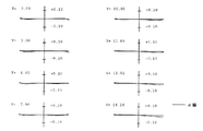
次に具体的な数値実施例1−7を示す。諸収差図及び横収差図並びに表中において、d線、g線、C線はそれぞれの波長に対する収差、Sはサジタル、Mはメリディオナル、FNO.はFナンバー、fは全系の焦点距離、Wは半画角(゜)、Yは像高、fB はバックフォーカス、Lはレンズ全長、Rは曲率半径、dはレンズ厚またはレンズ間隔、N(d)はd線に対する屈折率、ν(d)はd線に対するアッベ数を示す。Fナンバー、焦点距離、半画角、像高、バックフォーカス、レンズ全長及び変倍に伴って間隔が変化するレンズ間隔dは、短焦点距離端−中間焦点距離−長焦点距離端の順に示している。長さの単位は[mm]である。
回転対称非球面は次式で定義される。
x=cy2/[1+[1-(1+K)c2y2]1/2]+A4y4+A6y6+A8y8+A10y10+A12y12・・・
(但し、cは曲率(1/r)、yは光軸からの高さ、Kは円錐係数、A4、A6、A8、・・・・・は各次数の非球面係数、xはサグ量)
Next, specific numerical examples 1-7 will be described. In the various aberration diagrams and lateral aberration diagrams and tables, d-line, g-line and C-line are aberrations for each wavelength, S is sagittal, M is meridional, FNO. Is F-number, f is the focal length of the whole system, W Is half field angle (°), Y is image height, fB Is the back focus, L is the total lens length, R is the radius of curvature, d is the lens thickness or lens spacing, N (d) is the refractive index for the d-line, and ν (d) is the Abbe number for the d-line. The f-number, focal length, half angle of view, image height, back focus, total lens length, and lens interval d that changes with zooming are shown in the order of short focal length end-intermediate focal length-long focal length end. Yes. The unit of length is [mm].
A rotationally symmetric aspherical surface is defined by the following equation.
x = cy 2 / [1+ [1- (1 + K) c 2 y 2 ] 1/2 ] + A4y 4 + A6y 6 + A8y 8 + A10y 10 + A12y 12 ...
(Where c is the curvature (1 / r), y is the height from the optical axis, K is the conic coefficient, A4, A6, A8,... Are the aspheric coefficients of each order, and x is the sag amount)
全数値実施例1−7を通じて、第2レンズ群G2(第2Bレンズ群G2B)と像面Iとの間には、図示を省略した固定絞り(フレアカット絞り)が設けられており、この固定絞りがレンズデータの最終面となっている。固定絞りは、短焦点距離端から長焦点距離端への変倍に際し、像面Iに対して固定されており(光軸方向に移動せず)、周辺光量を最適化する(有害な余剰光束をカットする)機能を持つ。このため、バックフォーカスfBは、固定絞りと像面Iとの間の光軸上の距離であり、一定値となっている。 Through all numerical examples 1-7, a fixed stop (flare cut stop) (not shown) is provided between the second lens group G2 (second B lens group G2B) and the image plane I. The aperture is the final surface of the lens data. The fixed stop is fixed with respect to the image plane I (does not move in the direction of the optical axis) during zooming from the short focal length end to the long focal length end, and optimizes the peripheral light amount (harmful excess luminous flux) Has a function to cut. For this reason, the back focus fB is a distance on the optical axis between the fixed stop and the image plane I, and has a constant value.
[数値実施例1]
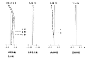
図1〜図6と表1〜表4は、本発明によるズームレンズ系の数値実施例1を示している。図1は長焦点距離端における無限遠合焦時のレンズ構成図、図2はその諸収差図、図3はその横収差図であり、図4は短焦点距離端における無限遠合焦時のレンズ構成図、図5はその諸収差図、図6はその横収差図である。表1は面データ、表2は非球面データ、表3は各種データ、表4はレンズ群データである。
[Numerical Example 1]
1 to 6 and Tables 1 to 4 show Numerical Example 1 of the zoom lens system according to the present invention. FIG. 1 is a lens configuration diagram when focusing at infinity at the long focal length end, FIG. 2 is a diagram showing various aberrations, FIG. 3 is a lateral aberration diagram, and FIG. 4 is a diagram when focusing at infinity at the short focal length end. FIG. 5 is a diagram showing various aberrations, and FIG. 6 is a diagram showing lateral aberrations. Table 1 shows surface data, Table 2 shows aspherical data, Table 3 shows various data, and Table 4 shows lens group data.
本数値実施例1のズームレンズ系は、物体側から順に、負の屈折力の第1レンズ群G1と、正の屈折力の第2レンズ群G2とからなる。 The zoom lens system according to Numerical Example 1 includes, in order from the object side, a first lens group G1 having a negative refractive power and a second lens group G2 having a positive refractive power.
第1レンズ群G1は、物体側から順に、物体側に凸の負メニスカスレンズ11と、物体側に凸の負メニスカスレンズ12と、物体側に凸の正メニスカスレンズ13とからなる。負メニスカスレンズ12は、その像側の面が非球面からなる。
The first lens group G1 includes, in order from the object side, a
第2レンズ群G2は、物体側から順に、正の屈折力の第2Aレンズ群G2Aと、開口絞りSと、正の屈折力の第2Bレンズ群G2Bとからなる。
第2Aレンズ群G2Aは、物体側から順に、両凸正レンズ21と、物体側から順に位置する両凸正レンズ22と両凹負レンズ23の接合レンズとからなる。
第2Bレンズ群G2Bは、物体側から順に、物体側に凸の正メニスカスレンズ25と、物体側に凸の負メニスカスレンズ26と、両凸正レンズ27とからなる。
The second lens group G2 includes, in order from the object side, a second A lens group G2A having a positive refractive power, an aperture stop S, and a second B lens group G2B having a positive refractive power.
The second A lens group G2A includes, in order from the object side, a biconvex
The second B lens group G2B includes, in order from the object side, a
(表1)
面データ
面番号 R d N(d) ν(d)
1 47.867 1.562 1.72916 54.7
2 17.097 6.060
3 46.121 3.240 1.68900 52.8
4* 19.326 8.761
5 33.188 3.660 1.76182 26.5
6 69.829 d6
7 64.514 3.060 1.74320 49.3
8 -175.121 0.100
9 30.912 5.753 1.49700 81.6
10 -30.274 1.340 1.78800 47.4
11 201.409 2.900
12絞 ∞ 1.650
13 62.059 1.993 1.71700 47.9
14 441.646 5.123
15 42.455 1.483 1.84666 23.8
16 20.899 1.267
17 64.749 3.166 1.60300 65.5
18 -37.958 d18
19 ∞
(表2)
非球面データ
面番号 K A4 A6 A8 A10
4 0.000 -0.1834E-04 -0.7423E-07 0.8340E-10 -0.8259E-12
(表3)
各種データ
ズーム比(変倍比) 1.89
短焦点距離端 中間焦点距離 長焦点距離端
FNO. 2.9 2.9 4.0
f 20.60 30.00 39.00
W 35.7 25.7 20.2
Y 14.24 14.24 14.24
fB 37.02 37.02 37.02
L 117.24 111.39 113.09
d6 27.117 10.964 2.796
d18 1.980 12.287 22.155
(表4)
レンズ群データ
群 始面 焦点距離
1 1 -31.12
2 7 34.12
(Table 1)
Surface data surface number R d N (d) ν (d)
1 47.867 1.562 1.72916 54.7
2 17.097 6.060
3 46.121 3.240 1.68900 52.8
4 * 19.326 8.761
5 33.188 3.660 1.76182 26.5
6 69.829 d6
7 64.514 3.060 1.74320 49.3
8 -175.121 0.100
9 30.912 5.753 1.49700 81.6
10 -30.274 1.340 1.78800 47.4
11 201.409 2.900
12 stops ∞ 1.650
13 62.059 1.993 1.71700 47.9
14 441.646 5.123
15 42.455 1.483 1.84666 23.8
16 20.899 1.267
17 64.749 3.166 1.60 300 65.5
18 -37.958 d18
19 ∞
(Table 2)
Aspheric data surface number K A4 A6 A8 A10
4 0.000 -0.1834E-04 -0.7423E-07 0.8340E-10 -0.8259E-12
(Table 3)
Various data zoom ratio (magnification ratio) 1.89
Short focal length end Intermediate focal length Long focal length end
FNO. 2.9 2.9 4.0
f 20.60 30.00 39.00
W 35.7 25.7 20.2
Y 14.24 14.24 14.24
fB 37.02 37.02 37.02
L 117.24 111.39 113.09
d6 27.117 10.964 2.796
d18 1.980 12.287 22.155
(Table 4)
Lens group data group Start surface Focal length
1 1 -31.12
2 7 34.12
[数値実施例2]
図7〜図12と表5〜表8は、本発明によるズームレンズ系の数値実施例2を示している。図7は長焦点距離端における無限遠合焦時のレンズ構成図、図8はその諸収差図、図9はその横収差図であり、図10は短焦点距離端における無限遠合焦時のレンズ構成図、図11はその諸収差図、図12はその横収差図である。表5は面データ、表6は非球面データ、表7は各種データ、表8はレンズ群データである。
[Numerical Example 2]
7 to 12 and Tables 5 to 8 show Numerical Example 2 of the zoom lens system according to the present invention. FIG. 7 is a lens configuration diagram at the time of focusing at infinity at the long focal length end, FIG. 8 is a diagram of various aberrations, FIG. 9 is a diagram of its lateral aberration, and FIG. FIG. 11 is a diagram showing various aberrations, and FIG. 12 is a diagram showing lateral aberrations. Table 5 shows surface data, Table 6 shows aspherical data, Table 7 shows various data, and Table 8 shows lens group data.
この数値実施例2のレンズ構成は、数値実施例1のレンズ構成と同様である。 The lens configuration of Numerical Example 2 is the same as the lens configuration of Numerical Example 1.
(表5)
面データ
面番号 R d N(d) ν(d)
1 49.778 1.566 1.74131 53.5
2 16.620 5.824
3 43.044 3.022 1.68900 52.8
4* 19.268 8.658
5 33.549 2.976 1.74498 27.2
6 75.431 d6
7 62.066 3.091 1.74120 45.0
8 -156.112 0.100
9 32.585 5.632 1.49700 81.6
10 -30.923 1.340 1.78800 47.4
11 180.404 2.900
12絞 ∞ 2.363
13 60.924 2.010 1.68002 56.1
14 432.231 4.959
15 47.435 2.101 1.84999 23.7
16 21.481 1.131
17 54.555 3.253 1.60300 65.5
18 -38.073 d18
19 ∞
(表6)
非球面データ
面番号 K A4 A6 A8 A10
4 0.000 -0.2028E-04 -0.8080E-07 0.8643E-10 -0.9806E-12
(表7)
各種データ
ズーム比(変倍比) 1.89
短焦点距離端 中間焦点距離 長焦点距離端
FNO. 2.9 2.9 4.0
f 20.60 30.00 39.00
W 35.7 25.8 20.2
Y 14.24 14.24 14.24
fB 37.13 37.13 37.13
L 116.60 111.28 113.36
d6 26.570 10.684 2.650
d18 1.980 12.542 22.654
(表8)
レンズ群データ
群 始面 焦点距離
1 1 -30.49
2 7 34.26
(Table 5)
Surface data surface number R d N (d) ν (d)
1 49.778 1.566 1.74131 53.5
2 16.620 5.824
3 43.044 3.022 1.68900 52.8
4 * 19.268 8.658
5 33.549 2.976 1.74498 27.2
6 75.431 d6
7 62.066 3.091 1.74120 45.0
8 -156.112 0.100
9 32.585 5.632 1.49700 81.6
10 -30.923 1.340 1.78800 47.4
11 180.404 2.900
12 stops ∞ 2.363
13 60.924 2.010 1.68002 56.1
14 432.231 4.959
15 47.435 2.101 1.84999 23.7
16 21.481 1.131
17 54.555 3.253 1.60 300 65.5
18 -38.073 d18
19 ∞
(Table 6)
Aspheric data surface number K A4 A6 A8 A10
4 0.000 -0.2028E-04 -0.8080E-07 0.8643E-10 -0.9806E-12
(Table 7)
Various data zoom ratio (magnification ratio) 1.89
Short focal length end Intermediate focal length Long focal length end
FNO. 2.9 2.9 4.0
f 20.60 30.00 39.00
W 35.7 25.8 20.2
Y 14.24 14.24 14.24
fB 37.13 37.13 37.13
L 116.60 111.28 113.36
d6 26.570 10.684 2.650
d18 1.980 12.542 22.654
(Table 8)
Lens group data group Start surface Focal length
1 1 -30.49
2 7 34.26
[数値実施例3]
図13〜図18と表9〜表12は、本発明によるズームレンズ系の数値実施例3を示している。図13は長焦点距離端における無限遠合焦時のレンズ構成図、図14はその諸収差図、図15はその横収差図であり、図16は短焦点距離端における無限遠合焦時のレンズ構成図、図17はその諸収差図、図18はその横収差図である。表9は面データ、表10は非球面データ、表11は各種データ、表12はレンズ群データである。
[Numerical Example 3]
13 to 18 and Tables 9 to 12 show Numerical Example 3 of the zoom lens system according to the present invention. FIG. 13 is a lens configuration diagram at the time of focusing at infinity at the long focal length end, FIG. 14 is a diagram showing various aberrations thereof, FIG. 15 is a diagram showing its lateral aberration, and FIG. FIG. 17 is a diagram showing various aberrations, and FIG. 18 is a diagram showing its lateral aberration. Table 9 shows surface data, Table 10 shows aspherical data, Table 11 shows various data, and Table 12 shows lens group data.
この数値実施例3のレンズ構成は、以下の点を除いて、数値実施例1のレンズ構成と同様である。
(1)第2Aレンズ群G2Aが、物体側から順に、両凸正レンズ21’と、物体側に凸の正メニスカスレンズ22’と、物体側から順に位置する両凸正レンズ23’と両凹負レンズ24’の接合レンズとからなる。
(2)第2Bレンズ群G2Bの正レンズ25が、両凸正レンズからなる。
The lens configuration of Numerical Example 3 is the same as the lens configuration of Numerical Example 1 except for the following points.
(1) The second A lens group G2A includes, in order from the object side, a biconvex
(2) The
(表9)
面データ
面番号 R d N(d) ν(d)
1 51.646 1.512 1.79799 47.6
2 16.830 5.572
3 38.967 1.900 1.71299 53.9
4* 19.125 7.396
5 32.357 3.713 1.76307 27.7
6 82.972 d6
7 78.939 2.577 1.80000 41.9
8 -1027.312 0.600
9 107.949 2.582 1.76000 43.3
10 289.084 0.713
11 31.892 5.702 1.49700 81.6
12 -28.374 1.340 1.79990 46.5
13 4542.080 2.700
14絞 ∞ 3.510
15 66.811 2.011 1.78102 48.2
16 -4706.309 2.426
17 48.729 1.480 1.83982 23.6
18 21.145 1.547
19 77.164 3.085 1.60300 65.5
20 -38.128 d20
21 ∞
(表10)
非球面データ
面番号 K A4 A6 A8 A10 A12
4 0.000 -0.2024E-04 -0.6888E-07 -0.2165E-10 -0.3632E-12 -0.1248E-14
(表11)
各種データ
ズーム比(変倍比) 1.89
短焦点距離端 中間焦点距離 長焦点距離端
FNO. 2.9 2.9 4.0
f 20.60 30.00 39.00
W 35.7 25.8 20.2
Y 14.24 14.24 14.24
fB 37.02 37.02 37.02
L 117.32 110.90 112.29
d6 27.956 11.301 2.878
d20 1.980 12.222 22.028
(表12)
レンズ群データ
群 始面 焦点距離
1 1 -31.70
2 7 34.54
(Table 9)
Surface data surface number R d N (d) ν (d)
1 51.646 1.512 1.79799 47.6
2 16.830 5.572
3 38.967 1.900 1.71299 53.9
4 * 19.125 7.396
5 32.357 3.713 1.76307 27.7
6 82.972 d6
7 78.939 2.577 1.80000 41.9
8 -1027.312 0.600
9 107.949 2.582 1.76000 43.3
10 289.084 0.713
11 31.892 5.702 1.49700 81.6
12 -28.374 1.340 1.79990 46.5
13 4542.080 2.700
14 stop ∞ 3.510
15 66.811 2.011 1.78102 48.2
16 -4706.309 2.426
17 48.729 1.480 1.83982 23.6
18 21.145 1.547
19 77.164 3.085 1.60 300 65.5
20 -38.128 d20
21 ∞
(Table 10)
Aspheric data surface number K A4 A6 A8 A10 A12
4 0.000 -0.2024E-04 -0.6888E-07 -0.2165E-10 -0.3632E-12 -0.1248E-14
(Table 11)
Various data zoom ratio (magnification ratio) 1.89
Short focal length end Intermediate focal length Long focal length end
FNO. 2.9 2.9 4.0
f 20.60 30.00 39.00
W 35.7 25.8 20.2
Y 14.24 14.24 14.24
fB 37.02 37.02 37.02
L 117.32 110.90 112.29
d6 27.956 11.301 2.878
d20 1.980 12.222 22.028
(Table 12)
Lens group data group Start surface Focal length
1 1 -31.70
2 7 34.54
[数値実施例4]
図19〜図24と表13〜表16は、本発明によるズームレンズ系の数値実施例4を示している。図19は長焦点距離端における無限遠合焦時のレンズ構成図、図20はその諸収差図、図21はその横収差図であり、図22は短焦点距離端における無限遠合焦時のレンズ構成図、図23はその諸収差図、図24はその横収差図である。表13は面データ、表14は非球面データ、表15は各種データ、表16はレンズ群データである。
[Numerical Example 4]
19 to 24 and Tables 13 to 16 show Numerical Example 4 of the zoom lens system according to the present invention. 19 is a lens configuration diagram at the time of focusing at infinity at the long focal length end, FIG. 20 is a diagram of various aberrations, FIG. 21 is a diagram of its lateral aberration, and FIG. 22 is a graph at the time of focusing at infinity at the short focal length end. FIG. 23 is a diagram showing various lens aberrations, and FIG. 24 is a diagram showing lateral aberrations. Table 13 shows surface data, Table 14 shows aspherical data, Table 15 shows various data, and Table 16 shows lens group data.
この数値実施例4のレンズ構成は、数値実施例1のレンズ構成と同様である。 The lens configuration of Numerical Example 4 is the same as the lens configuration of Numerical Example 1.
(表13)
面データ
面番号 R d N(d) ν(d)
1 47.976 1.550 1.72916 54.7
2 17.096 6.720
3 46.686 2.710 1.68900 52.8
4* 19.513 8.620
5 33.152 3.660 1.76182 26.5
6 69.323 d6
7 63.103 3.060 1.74320 49.3
8 -167.160 0.100
9 30.519 5.760 1.49700 81.6
10 -30.519 1.340 1.78800 47.4
11 216.000 2.900
12絞 ∞ 2.070
13 63.948 1.950 1.71700 47.9
14 342.890 4.470
15 42.360 1.480 1.84666 23.8
16 20.828 1.360
17 67.524 3.150 1.60300 65.5
18 -37.634 d18
19 ∞
(表14)
非球面データ
面番号 K A4 A6 A8 A10
4 0.000 -0.1770E-04 -0.6850E-07 0.5050E-10 -0.6878E-12
(表15)
各種データ
ズーム比(変倍比) 1.89
短焦点距離端 中間焦点距離 長焦点距離端
FNO. 2.9 2.9 4.0
f 20.59 30.00 39.00
W 35.8 25.8 20.2
Y 14.24 14.24 14.24
fB 37.02 37.02 37.02
L 116.95 111.18 112.94
d6 27.056 10.946 2.805
d18 1.980 12.320 22.215
(表16)
レンズ群データ
群 始面 焦点距離
1 1 -31.03
2 7 34.11
(Table 13)
Surface data surface number R d N (d) ν (d)
1 47.976 1.550 1.72916 54.7
2 17.096 6.720
3 46.686 2.710 1.68900 52.8
4 * 19.513 8.620
5 33.152 3.660 1.76182 26.5
6 69.323 d6
7 63.103 3.060 1.74320 49.3
8 -167.160 0.100
9 30.519 5.760 1.49700 81.6
10 -30.519 1.340 1.78800 47.4
11 216.000 2.900
12 stops ∞ 2.070
13 63.948 1.950 1.71700 47.9
14 342.890 4.470
15 42.360 1.480 1.84666 23.8
16 20.828 1.360
17 67.524 3.150 1.60 300 65.5
18 -37.634 d18
19 ∞
(Table 14)
Aspheric data surface number K A4 A6 A8 A10
4 0.000 -0.1770E-04 -0.6850E-07 0.5050E-10 -0.6878E-12
(Table 15)
Various data zoom ratio (magnification ratio) 1.89
Short focal length end Intermediate focal length Long focal length end
FNO. 2.9 2.9 4.0
f 20.59 30.00 39.00
W 35.8 25.8 20.2
Y 14.24 14.24 14.24
fB 37.02 37.02 37.02
L 116.95 111.18 112.94
d6 27.056 10.946 2.805
d18 1.980 12.320 22.215
(Table 16)
Lens group data group Start surface Focal length
1 1 -31.03
2 7 34.11
[数値実施例5]
図25〜図30と表17〜表20は、本発明によるズームレンズ系の数値実施例5を示している。図25は長焦点距離端における無限遠合焦時のレンズ構成図、図26はその諸収差図、図27はその横収差図であり、図28は短焦点距離端における無限遠合焦時のレンズ構成図、図29はその諸収差図、図30はその横収差図である。表17は面データ、表18は非球面データ、表19は各種データ、表20はレンズ群データである。
[Numerical Example 5]
25 to 30 and Tables 17 to 20 show Numerical Example 5 of the zoom lens system according to the present invention. FIG. 25 is a lens configuration diagram at the time of focusing at infinity at the long focal length end, FIG. 26 is a diagram showing various aberrations thereof, FIG. 27 is a lateral aberration diagram thereof, and FIG. FIG. 29 is a diagram showing various aberrations, and FIG. 30 is a diagram showing its lateral aberration. Table 17 shows surface data, Table 18 shows aspheric data, Table 19 shows various data, and Table 20 shows lens group data.
この数値実施例5のレンズ構成は、数値実施例3のレンズ構成と同様である。 The lens configuration of Numerical Example 5 is the same as the lens configuration of Numerical Example 3.
(表17)
面データ
面番号 R d N(d) ν(d)
1 55.395 1.722 1.77787 47.8
2 16.822 5.237
3 39.094 2.673 1.71299 53.9
4* 18.892 7.258
5 32.407 3.273 1.74077 27.8
6 92.638 d6
7 73.007 2.618 1.80000 40.1
8 -1842.033 0.100
9 96.495 2.674 1.73000 42.9
10 313.394 1.340
11 34.867 5.524 1.49700 81.6
12 -27.524 1.340 1.79999 44.3
13 539.709 2.700
14絞 ∞ 3.598
15 62.501 2.116 1.75999 51.3
16 -459.755 2.500
17 47.505 1.480 1.84666 23.8
18 21.335 1.347
19 84.112 3.056 1.60300 65.5
20 -37.920 d20
21 ∞
(表18)
非球面データ
面番号 K A4 A6 A8 A10
4 0.000 -0.2145E-04 -0.7588E-07 0.3377E-10 -0.8685E-12
(表19)
各種データ
ズーム比(変倍比) 1.89
短焦点距離端 中間焦点距離 長焦点距離端
FNO. 2.8 3.5 4.1
f 20.60 30.00 39.00
W 36.7 26.5 20.8
Y 14.70 14.70 14.70
fB 37.03 37.03 37.03
L 117.12 110.84 112.30
d6 27.550 11.012 2.648
d20 1.980 12.238 22.059
(表20)
レンズ群データ
群 始面 焦点距離
1 1 -31.57
2 7 34.45
(Table 17)
Surface data surface number R d N (d) ν (d)
1 55.395 1.722 1.77787 47.8
2 16.822 5.237
3 39.094 2.673 1.71299 53.9
4 * 18.892 7.258
5 32.407 3.273 1.74077 27.8
6 92.638 d6
7 73.007 2.618 1.80000 40.1
8 -1842.033 0.100
9 96.495 2.674 1.73000 42.9
10 313.394 1.340
11 34.867 5.524 1.49700 81.6
12 -27.524 1.340 1.79999 44.3
13 539.709 2.700
14 stop ∞ 3.598
15 62.501 2.116 1.75999 51.3
16 -459.755 2.500
17 47.505 1.480 1.84666 23.8
18 21.335 1.347
19 84.112 3.056 1.60 300 65.5
20 -37.920 d20
21 ∞
(Table 18)
Aspheric data surface number K A4 A6 A8 A10
4 0.000 -0.2145E-04 -0.7588E-07 0.3377E-10 -0.8685E-12
(Table 19)
Various data zoom ratio (magnification ratio) 1.89
Short focal length end Intermediate focal length Long focal length end
FNO. 2.8 3.5 4.1
f 20.60 30.00 39.00
W 36.7 26.5 20.8
Y 14.70 14.70 14.70
fB 37.03 37.03 37.03
L 117.12 110.84 112.30
d6 27.550 11.012 2.648
d20 1.980 12.238 22.059
(Table 20)
Lens group data group Start surface Focal length
1 1 -31.57
2 7 34.45
[数値実施例6]
図31〜図36と表21〜表24は、本発明によるズームレンズ系の数値実施例6を示している。図31は長焦点距離端における無限遠合焦時のレンズ構成図、図32はその諸収差図、図33はその横収差図であり、図34は短焦点距離端における無限遠合焦時のレンズ構成図、図35はその諸収差図、図36はその横収差図である。表21は面データ、表22は非球面データ、表23は各種データ、表24はレンズ群データである。
[Numerical Example 6]
FIGS. 31 to 36 and Tables 21 to 24 show Numerical Example 6 of the zoom lens system according to the present invention. 31 is a lens configuration diagram at the time of focusing at infinity at the long focal length end, FIG. 32 is a diagram showing various aberrations thereof, FIG. 33 is a diagram showing its lateral aberration, and FIG. 34 is a graph at focusing on infinity at the short focal length end. FIG. 35 is a diagram showing various aberrations, and FIG. 36 is a lateral aberration diagram. Table 21 shows surface data, Table 22 shows aspheric data, Table 23 shows various data, and Table 24 shows lens group data.
この数値実施例6のレンズ構成は、数値実施例3のレンズ構成と同様である。 The lens configuration of Numerical Example 6 is similar to the lens configuration of Numerical Example 3.
(表21)
面データ
面番号 R d N(d) ν(d)
1 54.869 1.918 1.79513 47.8
2 16.800 5.480
3 38.176 1.900 1.71299 53.9
4* 19.302 7.457
5 32.778 3.282 1.75332 27.5
6 86.558 d6
7 79.637 2.632 1.78309 45.7
8 -517.700 0.400
9 110.583 2.547 1.75871 32.7
10 261.030 0.900
11 32.450 5.701 1.49700 81.6
12 -28.208 1.340 1.79999 44.9
13 1082.321 2.700
14絞 ∞ 3.481
15 64.538 2.050 1.78958 47.6
16 -1595.871 2.697
17 48.360 1.536 1.83733 23.6
18 21.187 1.357
19 78.886 3.075 1.60300 65.5
20 -38.173 d20
21 ∞
(表22)
非球面データ
面番号 K A4 A6 A8 A10 A12
4 0.000 -0.2023E-04 -0.7262E-07 0.3586E-10 -0.6599E-12 -0.6902E-15
(表23)
各種データ
ズーム比(変倍比) 1.89
短焦点距離端 中間焦点距離 長焦点距離端
FNO. 2.9 3.5 4.0
f 20.60 30.00 39.00
W 36.7 26.5 20.8
Y 14.70 14.70 14.70
fB 37.02 37.02 37.02
L 117.32 110.92 112.31
d6 27.868 11.227 2.813
d20 1.980 12.220 22.021
(表24)
レンズ群データ
群 始面 焦点距離
1 1 -31.69
2 7 34.52
(Table 21)
Surface data surface number R d N (d) ν (d)
1 54.869 1.918 1.79513 47.8
2 16.800 5.480
3 38.176 1.900 1.71299 53.9
4 * 19.302 7.457
5 32.778 3.282 1.75332 27.5
6 86.558 d6
7 79.637 2.632 1.78309 45.7
8 -517.700 0.400
9 110.583 2.547 1.75871 32.7
10 261.030 0.900
11 32.450 5.701 1.49700 81.6
12 -28.208 1.340 1.79999 44.9
13 1082.321 2.700
14 stop ∞ 3.481
15 64.538 2.050 1.78958 47.6
16 -1595.871 2.697
17 48.360 1.536 1.83733 23.6
18 21.187 1.357
19 78.886 3.075 1.60 300 65.5
20 -38.173 d20
21 ∞
(Table 22)
Aspheric data surface number K A4 A6 A8 A10 A12
4 0.000 -0.2023E-04 -0.7262E-07 0.3586E-10 -0.6599E-12 -0.6902E-15
(Table 23)
Various data zoom ratio (magnification ratio) 1.89
Short focal length end Intermediate focal length Long focal length end
FNO. 2.9 3.5 4.0
f 20.60 30.00 39.00
W 36.7 26.5 20.8
Y 14.70 14.70 14.70
fB 37.02 37.02 37.02
L 117.32 110.92 112.31
d6 27.868 11.227 2.813
d20 1.980 12.220 22.021
(Table 24)
Lens group data group Start surface Focal length
1 1 -31.69
2 7 34.52
[数値実施例7]
図37〜図42と表25〜表28は、本発明によるズームレンズ系の数値実施例7を示している。図37は長焦点距離端における無限遠合焦時のレンズ構成図、図38はその諸収差図、図39はその横収差図であり、図40は短焦点距離端における無限遠合焦時のレンズ構成図、図41はその諸収差図、図42はその横収差図である。表25は面データ、表26は非球面データ、表27は各種データ、表28はレンズ群データである。
[Numerical Example 7]
37 to 42 and Tables 25 to 28 show Numerical Example 7 of the zoom lens system according to the present invention. 37 is a lens configuration diagram at the time of focusing at infinity at the long focal length end, FIG. 38 is a diagram showing various aberrations thereof, FIG. 39 is a diagram of its lateral aberration, and FIG. 40 is a diagram at focusing on infinity at the short focal length end. FIG. 41 is a diagram showing various aberrations, and FIG. 42 is a diagram showing its lateral aberration. Table 25 shows surface data, Table 26 shows aspheric data, Table 27 shows various data, and Table 28 shows lens group data.
この数値実施例7のレンズ構成は、以下の点を除いて、数値実施例3のレンズ構成と同様である。
(1)第2Bレンズ群G2Bが、物体側から順に、物体側に凸の負メニスカスレンズ25’と、両凸正レンズ26’とからなる。
The lens configuration of Numerical Example 7 is the same as the lens configuration of Numerical Example 3 except for the following points.
(1) The second B lens group G2B is composed of, in order from the object side, a
(表25)
面データ
面番号 R d N(d) ν(d)
1 49.052 3.403 1.77250 49.6
2 17.274 5.782
3 50.424 2.314 1.72916 54.7
4* 20.431 9.715
5 34.822 2.875 1.78898 24.4
6 71.256 d6
7 43.505 3.495 1.61161 40.2
8 -191.247 0.100
9 71.252 2.384 1.48749 70.2
10 293.490 0.250
11 31.095 5.782 1.49700 81.6
12 -31.095 1.340 1.78436 38.0
13 77.387 3.072
14絞 ∞ 4.329
15 43.041 4.269 1.78616 25.1
16 21.316 0.968
17 44.553 3.303 1.61800 63.4
18 -33.551 d18
19 ∞
(表26)
非球面データ
面番号 K A4 A6 A8 A10
4 0.000 -0.1570E-04 -0.5803E-07 0.6728E-10 -0.6190E-12
(表27)
各種データ
ズーム比(変倍比) 1.89
短焦点距離端 中間焦点距離 長焦点距離端
FNO. 2.8 3.4 4.0
f 20.60 30.00 39.00
W 36.7 26.5 20.8
Y 14.70 14.70 14.70
fB 37.02 37.02 37.02
L 117.92 113.00 115.32
d6 25.538 9.976 2.106
d18 1.980 12.625 22.818
(表28)
レンズ群データ
群 始面 焦点距離
1 1 -30.06
2 7 34.04
(Table 25)
Surface data surface number R d N (d) ν (d)
1 49.052 3.403 1.77250 49.6
2 17.274 5.782
3 50.424 2.314 1.72916 54.7
4 * 20.431 9.715
5 34.822 2.875 1.78898 24.4
6 71.256 d6
7 43.505 3.495 1.61161 40.2
8 -191.247 0.100
9 71.252 2.384 1.48749 70.2
10 293.490 0.250
11 31.095 5.782 1.49700 81.6
12 -31.095 1.340 1.78436 38.0
13 77.387 3.072
14 stop ∞ 4.329
15 43.041 4.269 1.78616 25.1
16 21.316 0.968
17 44.553 3.303 1.61800 63.4
18 -33.551 d18
19 ∞
(Table 26)
Aspheric data surface number K A4 A6 A8 A10
4 0.000 -0.1570E-04 -0.5803E-07 0.6728E-10 -0.6190E-12
(Table 27)
Various data zoom ratio (magnification ratio) 1.89
Short focal length end Intermediate focal length Long focal length end
FNO. 2.8 3.4 4.0
f 20.60 30.00 39.00
W 36.7 26.5 20.8
Y 14.70 14.70 14.70
fB 37.02 37.02 37.02
L 117.92 113.00 115.32
d6 25.538 9.976 2.106
d18 1.980 12.625 22.818
(Table 28)
Lens group data group Start surface Focal length
1 1 -30.06
2 7 34.04
各数値実施例の各条件式に対する値を表29に示す。
(表29)
実施例1 実施例2 実施例3 実施例4
条件式(1) 0.749 0.769 0.652 0.667
条件式(2) 1.114 1.039 1.482 1.382
条件式(3) 1.716 1.751 1.731 1.635
条件式(4) 52.8 52.8 53.9 52.8
条件式(5) -0.912 -0.890 -0.918 -0.910
実施例5 実施例6 実施例7
条件式(1) 0.790 0.720 0.658
条件式(2) 1.026 1.240 1.379
条件式(3) 1.719 1.803 1.62
条件式(4) 53.87 53.87 54.68
条件式(5) -0.916 -0.918 -0.883
Table 29 shows values for the conditional expressions of the numerical examples.
(Table 29)
Example 1 Example 2 Example 3 Example 4
Conditional expression (1) 0.749 0.769 0.652 0.667
Conditional expression (2) 1.114 1.039 1.482 1.382
Conditional expression (3) 1.716 1.751 1.731 1.635
Conditional expression (4) 52.8 52.8 53.9 52.8
Conditional expression (5) -0.912 -0.890 -0.918 -0.910
Example 5 Example 6 Example 7
Conditional expression (1) 0.790 0.720 0.658
Conditional expression (2) 1.026 1.240 1.379
Conditional expression (3) 1.719 1.803 1.62
Conditional expression (4) 53.87 53.87 54.68
Conditional expression (5) -0.916 -0.918 -0.883
表29から明らかなように、数値実施例1〜数値実施例7は、条件式(1)〜(5)を満足しており、諸収差図及び横収差図から明らかなように諸収差及び横収差は比較的よく補正されている。 As is clear from Table 29, Numerical Example 1 to Numerical Example 7 satisfy the conditional expressions (1) to (5). As is apparent from the various aberration diagrams and lateral aberration diagrams, Aberrations are corrected relatively well.
本発明の特許請求の範囲に含まれるズームレンズ系に、実質的なパワーを有さないレンズまたはレンズ群を追加したとしても、本発明の技術的範囲に含まれる(本発明の技術的範囲を回避したことにはならない)。 Even if a lens or a lens group having no substantial power is added to the zoom lens system included in the scope of claims of the present invention, it is included in the technical scope of the present invention. It ’s not avoided.)
G1 負の屈折力の第1レンズ群
11 負レンズ
12 負レンズ
13 正レンズ
G2 正の屈折力の第2レンズ群
G2A 正の屈折力の第2Aレンズ群
21 正レンズ
22 正レンズ
23 負レンズ
21’ 正レンズ
22’ 正レンズ
23’ 正レンズ
24’ 負レンズ
G2B 正の屈折力の第2Bレンズ群
25 正レンズ
26 負レンズ
27 正レンズ
25’ 負レンズ
26’ 正レンズ
S 開口絞り
I 像面
G1
Claims (6)
第2レンズ群は、物体側から順に、正の屈折力の第2Aレンズ群と、開口絞りと、正の屈折力の第2Bレンズ群とからなり、
第2Aレンズ群は、1枚または2枚の正レンズと、正レンズと負レンズの接合レンズとからなり、
次の条件式(1)を満足することを特徴とするズームレンズ系。
(1)0.65<f2A/f2B<1.0
但し、
f2A:第2Aレンズ群の焦点距離、
f2B:第2Bレンズ群の焦点距離。 In order from the object side, a first lens unit having a negative refractive power and a second lens unit having a positive refractive power are arranged. When zooming from the short focal length end to the long focal length end, In a zoom lens system in which the distance between the two lens groups is reduced,
The second lens group includes, in order from the object side, a second A lens group having a positive refractive power, an aperture stop, and a second B lens group having a positive refractive power.
The second A lens group includes one or two positive lenses and a cemented lens of a positive lens and a negative lens.
A zoom lens system characterized by satisfying the following conditional expression (1):
(1) 0.65 <f2A / f2B <1.0
However,
f2A: focal length of the 2A lens group,
f2B: focal length of the second B lens group.
(2)0.5<FP/RP<1.5
但し、
FP:短焦点距離端における開口絞りより物体側のレンズ群の焦点距離、
RP:短焦点距離端における開口絞りより像側のレンズ群の焦点距離。 2. The zoom lens system according to claim 1, wherein the zoom lens system satisfies the following conditional expression (2).
(2) 0.5 <FP / RP <1.5
However,
FP: focal length of the lens unit on the object side from the aperture stop at the short focal length end,
RP: the focal length of the lens group on the image side from the aperture stop at the short focal length end.
(3)1.6<fasp/f1<5.0
但し、
fasp:第1レンズ群中の非球面レンズの焦点距離、
f1:第1レンズ群の焦点距離。 4. The zoom lens system according to claim 1, wherein the first lens group includes an aspheric lens, and satisfies the following conditional expression (3): 5.
(3) 1.6 <fasp / f1 <5.0
However,
fasp: focal length of the aspherical lens in the first lens group,
f1: Focal length of the first lens group.
(4)Aνd>52.5
但し、
Aνd:第1レンズ群中の非球面レンズのd線に対するアッベ数。 5. The zoom lens system according to claim 4, wherein the zoom lens system satisfies the following conditional expression (4).
(4) Aνd> 52.5
However,
Avd: Abbe number with respect to d-line of the aspherical lens in the first lens group.
(5)−0.92<f1/f2<−0.8
但し、
f1:第1レンズ群の焦点距離、
f2:第2レンズ群の焦点距離。 The zoom lens system according to any one of claims 1 to 5, wherein the zoom lens system satisfies the following conditional expression (5).
(5) -0.92 <f1 / f2 <-0.8
However,
f1: the focal length of the first lens group,
f2: Focal length of the second lens group.
Priority Applications (4)
| Application Number | Priority Date | Filing Date | Title |
|---|---|---|---|
| JP2013136070A JP5678997B2 (en) | 2013-06-28 | 2013-06-28 | Zoom lens system |
| PCT/JP2014/065752 WO2014208367A1 (en) | 2013-06-28 | 2014-06-13 | Zoom lens system |
| US14/901,365 US20160154223A1 (en) | 2013-06-28 | 2014-06-13 | Zoom lens system |
| EP14818229.8A EP3015896B1 (en) | 2013-06-28 | 2014-06-13 | Zoom lens system |
Applications Claiming Priority (1)
| Application Number | Priority Date | Filing Date | Title |
|---|---|---|---|
| JP2013136070A JP5678997B2 (en) | 2013-06-28 | 2013-06-28 | Zoom lens system |
Publications (2)
| Publication Number | Publication Date |
|---|---|
| JP2015011156A JP2015011156A (en) | 2015-01-19 |
| JP5678997B2 true JP5678997B2 (en) | 2015-03-04 |
Family
ID=52141710
Family Applications (1)
| Application Number | Title | Priority Date | Filing Date |
|---|---|---|---|
| JP2013136070A Active JP5678997B2 (en) | 2013-06-28 | 2013-06-28 | Zoom lens system |
Country Status (4)
| Country | Link |
|---|---|
| US (1) | US20160154223A1 (en) |
| EP (1) | EP3015896B1 (en) |
| JP (1) | JP5678997B2 (en) |
| WO (1) | WO2014208367A1 (en) |
Families Citing this family (4)
| Publication number | Priority date | Publication date | Assignee | Title |
|---|---|---|---|---|
| CN107533212A (en) * | 2015-03-27 | 2018-01-02 | 奥林巴斯株式会社 | Zoom lens and the camera device with the zoom lens |
| TWI716562B (en) * | 2017-03-15 | 2021-01-21 | 揚明光學股份有限公司 | Zoom lens |
| US20180252900A1 (en) * | 2017-03-03 | 2018-09-06 | Young Optics Inc. | Zoom lens |
| CN112882207B (en) * | 2021-04-29 | 2021-07-06 | 江西联益光学有限公司 | Optical imaging lens and imaging apparatus |
Family Cites Families (12)
| Publication number | Priority date | Publication date | Assignee | Title |
|---|---|---|---|---|
| JPH0588084A (en) | 1991-09-30 | 1993-04-09 | Nikon Corp | Zoom lens of two-group constitution |
| JPH10161024A (en) * | 1996-11-28 | 1998-06-19 | Minolta Co Ltd | Zoom lens having camera shake correcting function |
| JP4654506B2 (en) | 1999-12-02 | 2011-03-23 | 株式会社ニコン | Zoom lens |
| JP2006053437A (en) * | 2004-08-13 | 2006-02-23 | Nikon Corp | Zoom lens |
| US7277232B2 (en) * | 2003-01-24 | 2007-10-02 | Nikon Corporation | Zoom lens system |
| JP5263589B2 (en) * | 2008-08-13 | 2013-08-14 | 株式会社ニコン | Zoom lens system, optical apparatus equipped with the zoom lens system, and zooming method using the zoom lens system |
| JP5430130B2 (en) | 2008-11-27 | 2014-02-26 | キヤノン株式会社 | Zoom lens and imaging apparatus having the same |
| JP2010186011A (en) * | 2009-02-12 | 2010-08-26 | Olympus Imaging Corp | Wide angle optical system and image pickup apparatus using the same |
| JP5463865B2 (en) * | 2009-11-13 | 2014-04-09 | 株式会社ニコン | Lens system, optical equipment |
| JP5609072B2 (en) * | 2009-11-13 | 2014-10-22 | 株式会社ニコン | Lens system, optical device, and manufacturing method of lens system |
| JP5724639B2 (en) * | 2011-05-30 | 2015-05-27 | リコーイメージング株式会社 | Zoom lens system and optical apparatus using the same |
| US9256059B2 (en) * | 2012-07-10 | 2016-02-09 | Konica Minolta, Inc. | Zoom lens system, imaging optical device, and digital appliance |
-
2013
- 2013-06-28 JP JP2013136070A patent/JP5678997B2/en active Active
-
2014
- 2014-06-13 US US14/901,365 patent/US20160154223A1/en not_active Abandoned
- 2014-06-13 WO PCT/JP2014/065752 patent/WO2014208367A1/en active Application Filing
- 2014-06-13 EP EP14818229.8A patent/EP3015896B1/en active Active
Also Published As
| Publication number | Publication date |
|---|---|
| EP3015896B1 (en) | 2020-08-12 |
| WO2014208367A1 (en) | 2014-12-31 |
| JP2015011156A (en) | 2015-01-19 |
| EP3015896A1 (en) | 2016-05-04 |
| EP3015896A4 (en) | 2017-02-22 |
| US20160154223A1 (en) | 2016-06-02 |
Similar Documents
| Publication | Publication Date | Title |
|---|---|---|
| JP6314471B2 (en) | Zoom lens system | |
| JP5362757B2 (en) | High zoom ratio zoom lens system | |
| JP2007304241A (en) | Zoom lens system | |
| JP2013210605A (en) | Zoom lens system and electronic imaging apparatus including the same | |
| JP5617884B2 (en) | Zoom lens system and electronic imaging apparatus including the same | |
| JP5482245B2 (en) | Wide-angle zoom lens system | |
| JP5664363B2 (en) | Zoom lens system and electronic imaging apparatus including the same | |
| JP5678997B2 (en) | Zoom lens system | |
| JP2012247688A (en) | Zoom lens system and optical device using the same | |
| JP2012247689A (en) | Zoom lens system and optical device using the same | |
| JP2014142520A (en) | Imaging lens system | |
| EP2749926A2 (en) | Zoom lens of the retrofocus type having four lens groups | |
| JP6160254B2 (en) | Zoom lens system | |
| JP6252175B2 (en) | Zoom lens system | |
| JP5542639B2 (en) | Zoom lens system | |
| JP5579573B2 (en) | Zoom lens system and electronic imaging apparatus using the same | |
| JP7172776B2 (en) | shooting lens system | |
| JP6221642B2 (en) | Zoom lens system | |
| JP2012083706A (en) | Zoom lens system | |
| JP5631705B2 (en) | Zoom lens system | |
| JP6597086B2 (en) | Zoom lens system | |
| JP2016143012A (en) | Zoom lens system | |
| JP6439365B2 (en) | Zoom lens system | |
| JP2015125385A (en) | Zoom lens system | |
| JP6417737B2 (en) | Single focus lens system |
Legal Events
| Date | Code | Title | Description |
|---|---|---|---|
| A521 | Request for written amendment filed |
Free format text: JAPANESE INTERMEDIATE CODE: A523 Effective date: 20141105 |
|
| A621 | Written request for application examination |
Free format text: JAPANESE INTERMEDIATE CODE: A621 Effective date: 20141105 |
|
| A871 | Explanation of circumstances concerning accelerated examination |
Free format text: JAPANESE INTERMEDIATE CODE: A871 Effective date: 20141105 |
|
| TRDD | Decision of grant or rejection written | ||
| A975 | Report on accelerated examination |
Free format text: JAPANESE INTERMEDIATE CODE: A971005 Effective date: 20141126 |
|
| A01 | Written decision to grant a patent or to grant a registration (utility model) |
Free format text: JAPANESE INTERMEDIATE CODE: A01 Effective date: 20141209 |
|
| A61 | First payment of annual fees (during grant procedure) |
Free format text: JAPANESE INTERMEDIATE CODE: A61 Effective date: 20141222 |
|
| R150 | Certificate of patent or registration of utility model |
Ref document number: 5678997 Country of ref document: JP Free format text: JAPANESE INTERMEDIATE CODE: R150 |
|
| R250 | Receipt of annual fees |
Free format text: JAPANESE INTERMEDIATE CODE: R250 |
|
| R250 | Receipt of annual fees |
Free format text: JAPANESE INTERMEDIATE CODE: R250 |
|
| R250 | Receipt of annual fees |
Free format text: JAPANESE INTERMEDIATE CODE: R250 |
|
| R250 | Receipt of annual fees |
Free format text: JAPANESE INTERMEDIATE CODE: R250 |
|
| R250 | Receipt of annual fees |
Free format text: JAPANESE INTERMEDIATE CODE: R250 |
|
| R250 | Receipt of annual fees |
Free format text: JAPANESE INTERMEDIATE CODE: R250 |
|
| R250 | Receipt of annual fees |
Free format text: JAPANESE INTERMEDIATE CODE: R250 |