JP5678933B2 - Sheet metal drilling device having punch for punching sheet metal - Google Patents
Sheet metal drilling device having punch for punching sheet metal Download PDFInfo
- Publication number
- JP5678933B2 JP5678933B2 JP2012176543A JP2012176543A JP5678933B2 JP 5678933 B2 JP5678933 B2 JP 5678933B2 JP 2012176543 A JP2012176543 A JP 2012176543A JP 2012176543 A JP2012176543 A JP 2012176543A JP 5678933 B2 JP5678933 B2 JP 5678933B2
- Authority
- JP
- Japan
- Prior art keywords
- punch
- cylindrical
- sheet metal
- hole
- circular
- Prior art date
- Legal status (The legal status is an assumption and is not a legal conclusion. Google has not performed a legal analysis and makes no representation as to the accuracy of the status listed.)
- Active
Links
- 239000002184 metal Substances 0.000 title claims description 86
- 238000004080 punching Methods 0.000 title claims description 19
- 238000005553 drilling Methods 0.000 title claims description 12
- 230000037431 insertion Effects 0.000 claims 1
- 238000003780 insertion Methods 0.000 claims 1
- 238000010586 diagram Methods 0.000 description 6
- 238000000034 method Methods 0.000 description 6
- 230000015572 biosynthetic process Effects 0.000 description 3
- 238000010008 shearing Methods 0.000 description 3
- 230000006866 deterioration Effects 0.000 description 2
- 230000000694 effects Effects 0.000 description 2
- 230000002093 peripheral effect Effects 0.000 description 2
Images


Description
本発明は、薄板金属の孔明け用のパンチ及びこのパンチを具備した薄板金属の孔明け装置並びにその方法に関する。 The present invention relates to a punch for punching a sheet metal, a punching apparatus for a sheet metal provided with the punch, and a method thereof.
ダイスの孔径よりも小さい外径を有した円柱状のパンチ本体とこのパンチ本体の一端面に一体的に形成された円錐形の突起とを有したパンチを薄板金属に押し付け、パンチの突起により薄板金属に先行して突き破り孔を明け、突き破り孔に挿入された突起で薄板金属の移動を規制した状態で更にパンチ本体をダイスの円孔に、当該ダイスの円孔の一端から挿入することによりパンチ本体と協同してダイスの円孔の一端を規定するダイスの円筒状内面の円環状縁の周りで薄板金属を破断させて薄板金属に貫通孔を形成するようにした孔明け装置が提案されている(例えば特許文献1及び2参照)。 A punch having a cylindrical punch body having an outer diameter smaller than the hole diameter of the die and a conical protrusion integrally formed on one end face of the punch body is pressed against a thin metal plate, and the thin plate is formed by the protrusion of the punch. A punch is made by drilling a piercing hole in advance of the metal, and further inserting the punch body into the die hole from one end of the die hole in a state where the movement of the sheet metal is restricted by the protrusion inserted into the piercing hole. A drilling device has been proposed in which a sheet metal is broken around an annular edge of a cylindrical inner surface of a die that defines one end of a die hole in cooperation with the main body to form a through hole in the sheet metal. (For example, see Patent Documents 1 and 2).
斯かる孔明け装置によれば、突起でもって薄板金属を位置決めし、しかも、剪断力よりも主として引っ張り力を薄板金属に加えて貫通孔を形成するために、バリを生じさせることなく正確に貫通孔を薄板金属に形成できるのであるが、薄板金属に形成する貫通孔の孔径が小さくなると、ダイスの円筒状内面の円環状縁と協同して引っ張り力を薄板金属に加えるパンチ本体の円環状の端面が当該端面の外周縁の湾曲部と突起の底面とで実質的に存在しなくなり、パンチの突起による薄板金属への突き破り孔の形成に続いてパンチ本体により突き破り孔自体が拡径されて、引っ張り力による薄板金属への貫通孔の形成ができなくなる虞がある。 According to such a drilling device, the thin plate metal is positioned by the protrusion, and moreover, a tensile force rather than a shearing force is applied to the thin metal plate to form a through hole, so that the through hole can be accurately penetrated without causing a burr. Although the hole can be formed in the sheet metal, when the hole diameter of the through-hole formed in the sheet metal is reduced, the annular shape of the punch body that applies a tensile force to the sheet metal in cooperation with the annular edge of the cylindrical inner surface of the die. The end surface is substantially absent from the curved portion of the outer peripheral edge of the end surface and the bottom surface of the projection, and the piercing hole itself is expanded by the punch body following the formation of the piercing hole in the sheet metal by the projection of the punch, There is a possibility that the through hole cannot be formed in the thin metal plate by the pulling force.
そこで、パンチ本体に一定の大きさ(広さ)の端面を確保するために、円錐形の突起の先端の円錐角を小さくして突起の底面の広さを小さくすると、極めて細い突起となって突起の強度を確保することが困難となる上に、耐久性が劣化する一方、これに代えて、突起の全体の高さを低くして突起の底面の広さを小さくすると、突起による突き破り孔の形成後に突き破り孔から突起が抜け出て薄板金属の移動の規制を行い得なくなって、ダイスの円筒状内面の円環状縁と協同してパンチ本体の端面により均等に引っ張り力を薄板金属に加えることができなくなる虞がある。 Therefore, in order to secure an end surface of a certain size (wideness) in the punch body, if the cone angle at the tip of the conical protrusion is reduced to reduce the width of the bottom surface of the protrusion, the protrusion becomes extremely thin. While it becomes difficult to ensure the strength of the protrusion and the durability deteriorates, if the overall height of the protrusion is lowered and the width of the bottom surface of the protrusion is reduced, the breakthrough hole by the protrusion After the formation of the punch, the protrusions come out of the piercing holes and the movement of the sheet metal can no longer be controlled, and the pulling force is uniformly applied to the sheet metal by the end face of the punch body in cooperation with the annular edge of the cylindrical inner surface of the die. There is a risk that it will not be possible.
本発明は、前記諸点に鑑みてなされたものであって、その目的とするところは、パンチ本体に一定の大きさ(広さ)の端面を確保できるにも拘わらず突起の強度を確保できて耐久性の劣化を招来せず、しかも、突き破り孔の形成後においても突起でもって薄板金属の移動の規制を確保できて薄板金属を位置決めできると共にパンチ本体による突き破り孔自体の拡径を回避でき、而して、パンチ本体と協同してダイスの孔の一端を規定するダイスの筒状内面の環状縁の周りで薄板金属を引っ張りにより確実に破断させて薄板金属に貫通孔を形成できる薄板金属の孔明け用のパンチ及びこのパンチを具備した薄板金属の孔明け装置並びにその方法を提供することにある。 The present invention has been made in view of the above-mentioned points, and the object of the present invention is to ensure the strength of the projections despite the fact that the punch body can secure an end surface of a certain size (width). It does not lead to deterioration of durability, and even after the formation of the piercing hole, it is possible to secure the regulation of the movement of the thin metal plate with the protrusion, and to position the thin metal plate, and to avoid the diameter expansion of the piercing hole itself by the punch body, Thus, the thin plate metal can be formed by forming a through hole in the thin plate metal by pulling the thin plate metal around the annular edge of the cylindrical inner surface of the die that defines one end of the die hole in cooperation with the punch body. An object of the present invention is to provide a punch for punching, an apparatus for punching a thin metal plate provided with the punch, and a method thereof.
本発明による薄板金属の孔明け用のパンチは、柱状のパンチ本体と、この本体の一方の端面に一体的に設けられた突起とを具備しており、ここで、突起は、パンチ本体の一方の端面に底面及び頂面をもって一体的に設けられた柱状部と、この柱状部の頂面に一体的に設けられた錐状部とを具備しており、パンチ本体は、軸心に平行に伸びた筒面と、柱状部の底面を囲繞していると共に軸心に直交して伸びた環状面と、この環状面の外縁から筒面の一縁まで伸びる湾曲面とを具備している。 A punch for punching a thin metal plate according to the present invention includes a columnar punch body and a protrusion integrally provided on one end surface of the body, where the protrusion is one of the punch bodies. A columnar portion integrally provided with a bottom surface and a top surface on the end surface of the plate, and a conical portion integrally provided on the top surface of the columnar portion. The punch body is parallel to the axis. An extended cylindrical surface, an annular surface surrounding the bottom surface of the columnar portion and extending perpendicular to the axis, and a curved surface extending from the outer edge of the annular surface to one edge of the cylindrical surface are provided.
斯かる薄板金属の孔明け用のパンチによれば、突起がパンチ本体の一方の端面に底面及び頂面をもって一体的に設けられた柱状部を有しているために、突起の錐状部の頂角を十分な強度及び耐久性を得られるように大きくすると共に突起による突き破り孔の形成後における突き破り孔からの突起の抜け出しを防止するように突起の全体を高くしても、突起の柱状部の底面を囲繞していると共に軸心に直交して伸びた環状面を十分な広さをもってパンチ本体の端面に確保でき、而して、パンチ本体による突き破り孔自体の拡径を回避できる上に、パンチ本体と協同してダイスの孔の一端を規定するダイスの筒状内面の環状縁の周りで薄板金属を引っ張りにより確実に破断させてバリを生じさせることなく薄板金属に貫通孔を精度よく形成できる。 According to such a punch for punching a thin metal plate, since the projection has a columnar portion integrally provided with a bottom surface and a top surface on one end surface of the punch main body, Even if the height of the protrusion is made high so that the apex angle is increased so that sufficient strength and durability can be obtained and the protrusion is prevented from coming out of the piercing hole after the piercing hole is formed by the protrusion, the columnar portion of the protrusion An annular surface that surrounds the bottom surface of the punch body and that extends perpendicular to the axis can be secured to the end surface of the punch body with a sufficient width, and thus the punch body itself can be prevented from expanding its diameter. The through hole is accurately formed in the sheet metal without causing burrs by pulling the sheet metal securely around the annular edge of the cylindrical inner surface of the die that defines one end of the die hole in cooperation with the punch body. Can be formed
本発明の薄板金属の孔明け用のパンチは、突起により薄板金属に突き破り孔を明け、突き破り孔に挿入された突起の柱状部で薄板金属の移動を規制した状態で更にパンチをダイスの孔に、当該ダイスの孔の一端から挿入することによりダイスの孔の一端を規定するダイスの筒状内面の環状縁の周りで薄板金属を破断させて薄板金属に貫通孔を形成するようになっている薄板金属の孔明け装置に用いるとよい。 The punch for punching a thin metal plate according to the present invention has a punch hole formed in the thin metal plate by a protrusion, and the punch is further formed into a die hole in a state where the movement of the thin metal plate is restricted by the columnar portion of the protrusion inserted into the break hole. By inserting from one end of the die hole, the sheet metal is broken around the annular edge of the cylindrical inner surface of the die that defines one end of the die hole, thereby forming a through hole in the sheet metal. It is good to use for the punching device of a thin metal plate.
本発明において、パンチ本体は、三角柱、四角柱、多角柱を含む柱状であって、錐状部は、三角錐、四角錐、多角錐を含む錐状あればよいのであるが、好ましい例では、夫々円柱状及び円錐状であり、この場合には、本発明に係る薄板金属の孔明け用のパンチは、円柱状のパンチ本体と、このパンチ本体の一方の円形端面に一体的に設けられた突起とを具備しており、ここで、突起は、パンチ本体の一方の円形端面に、当該円形端面と同心に配されている円形底面及び円形頂面をもって一体的に設けられた円柱状部と、この円柱状部の円形頂面に一体的に設けられた円錐状部とを具備しており、パンチ本体は、軸心に平行に伸びた円筒面と、円柱状部の円形底面を囲繞していると共に軸心に直交して伸びた円環状面と、この円環状面の外縁から円筒面の一縁まで伸びる湾曲面とを具備していてもよい。 In the present invention, the punch body is a columnar shape including a triangular prism, a quadrangular column, and a polygonal column, and the conical portion only needs to be a conical shape including a triangular pyramid, a quadrangular pyramid, and a polygonal pyramid. In this case, the punch for punching the thin metal plate according to the present invention is provided integrally with the cylindrical punch body and one circular end face of the punch body. Here, the protrusion is formed on the circular end surface of the punch main body, and the cylindrical portion integrally provided with the circular bottom surface and the circular top surface concentrically with the circular end surface. And a conical portion integrally provided on the circular top surface of the columnar portion, and the punch body surrounds the cylindrical surface extending parallel to the axis and the circular bottom surface of the columnar portion. And an annular surface extending perpendicular to the axis and the outer edge of the annular surface And a curved surface extending to one edge of the cylindrical surface may be equipped.
円柱状のパンチ本体を有した孔明け用のパンチでは、パンチ本体の半径をr1、湾曲面の曲率半径をr2、円柱状部の半径をr3、円柱状部の高さをh、孔明けすべき薄板金属の厚みをtとした場合、r3<r1−r2であって、h>t+r3であるとよい。 In a punch for punching having a cylindrical punch body, the radius of the punch body should be r1, the radius of curvature of the curved surface should be r2, the radius of the cylindrical part should be r3, the height of the cylindrical part should be h, and the hole should be punched When the thickness of the thin metal plate is t, r3 <r1-r2 and h> t + r3 may be satisfied.
円柱状のパンチ本体の直径は、好ましい例では、1mmから25mm、1mmから10mm又は1mmから5mmの範囲であるが、本発明は、これらに限定されない。 In a preferred example, the diameter of the cylindrical punch body is in the range of 1 mm to 25 mm, 1 mm to 10 mm, or 1 mm to 5 mm, but the present invention is not limited thereto.
円柱状のパンチ本体を有した薄板金属の孔明け用のパンチは、突起により薄板金属に突き破り孔を明け、突き破り孔に挿入された突起の円柱状部で薄板金属の移動を規制した状態で更にパンチをダイスの円孔に、当該円孔の一端から挿入することにより円孔の一端を規定するダイスの円筒状内面の円環状縁の周りで薄板金属を破断させて薄板金属に貫通孔を形成するようになっている薄板金属の孔明け装置に用いるとよい。 The punch for punching a thin metal plate having a cylindrical punch body is further formed in a state where a hole is drilled in the thin metal plate by the protrusion, and the movement of the thin metal plate is restricted by the cylindrical portion of the protrusion inserted into the through hole. By inserting the punch into the hole of the die from one end of the hole, the sheet metal is broken around the annular edge of the cylindrical inner surface of the die that defines one end of the hole to form a through hole in the sheet metal. It is good to use for the punching apparatus of the sheet metal which has become.
本発明において、突起の円柱状部は、円形底面及び円形頂面が互いに同径の円柱状部であっても、これに代えて、円形底面よりも円形頂面の直径が小さく、しかも、截頭円錐面を伸ばした場合の頂点の角度が突起の円錐状部の頂点の角度よりも小さい所謂截頭円錐状の円柱状部であってもよく、また、湾曲面は、バリの原因となる剪断の効果を減じて薄板金属をより良好に引っ張り破断させるために、好ましくは、0.1mmから5mmの曲率半径Rをもっているとよい。 In the present invention, the cylindrical portion of the protrusion may be a cylindrical portion having the same diameter in the circular bottom surface and the circular top surface. Instead, the diameter of the circular top surface is smaller than that of the circular bottom surface. It may be a so-called frustoconical columnar portion in which the angle of the apex when the head cone surface is extended is smaller than the angle of the apex of the conical portion of the projection, and the curved surface causes burrs. In order to reduce the shearing effect and to better pull and break the sheet metal, it is preferable to have a curvature radius R of 0.1 mm to 5 mm.
薄板金属の孔明け装置は、上記のいずれかの態様の薄板金属の孔明け用のパンチと、このパンチが挿入される孔又は円孔を有したダイスとを具備している。 A sheet metal drilling apparatus includes the punch for punching a sheet metal according to any one of the above aspects and a die having a hole or a circular hole into which the punch is inserted.
ダイスの孔又は円孔に対するパンチ本体のクリアランスとしての差は、薄板金属の厚みをtとすると、0.15t以上であって、2mm以下であればよい。 The difference as the clearance of the punch body with respect to the die hole or the circular hole is 0.15 t or more and 2 mm or less, where t is the thickness of the sheet metal.
上記の薄板金属の孔明け装置により薄板金属に貫通孔を形成する本発明による方法は、突起により薄板金属に突き破り孔を明け、突き破り孔に挿入された突起の柱状部又は円柱状部で薄板金属の移動を規制した状態で更にパンチをダイスの孔又は円孔に、当該孔又は円孔の一端から挿入することにより孔又は円孔の一端を規定するダイスの筒状内面又は円筒状内面の環状縁又は円環状縁の周りで薄板金属を破断させることからなる。 The method according to the present invention for forming a through-hole in a thin metal plate by the above-described thin metal hole drilling device is a method in which a through-hole is formed in a thin metal plate by a protrusion, and the thin plate metal is formed by a columnar portion or a cylindrical portion of the protrusion inserted into the through-hole. The cylindrical inner surface of the die or the annular inner surface of the die that defines one end of the hole or circular hole by inserting the punch into the hole or circular hole of the die from one end of the hole or circular hole with the movement of It consists of breaking a sheet metal around an edge or an annular edge.
本発明の孔明け装置又は方法によって孔明けされる薄板金属は、良好な結果を得るには、その板厚が0.4mmから2.0mm程度のものであるが、より良好な結果を得るには、その板厚が0.6mmから1.6mm程度のものである。 The sheet metal drilled by the drilling apparatus or method of the present invention has a thickness of about 0.4 mm to 2.0 mm in order to obtain good results. Has a thickness of about 0.6 mm to 1.6 mm.
本発明によれば、パンチ本体に一定の大きさ(広さ)の端面を確保できるにも拘わらず突起の強度を確保できて耐久性の劣化を招来せず、しかも、突き破り孔の形成後においても突起でもって薄板金属の移動の規制を確保できて薄板金属を位置決めできると共にパンチ本体による突き破り孔自体の拡径を回避でき、而して、パンチ本体と協同してダイスの孔の一端を規定するダイスの筒状内面の環状縁の周りで薄板金属を引っ張りにより確実に破断させて薄板金属に貫通孔を形成できる薄板金属の孔明け用のパンチ及びこのパンチを具備した薄板金属の孔明け装置並びにその方法を提供することができる。 According to the present invention, although the end face of a certain size (wide) can be secured on the punch body, the strength of the projection can be secured without causing deterioration in durability, and after the piercing hole is formed. In addition, it is possible to secure the regulation of the movement of the sheet metal with the projections, and to position the sheet metal and to avoid the diameter expansion of the piercing hole itself by the punch body, thus defining one end of the die hole in cooperation with the punch body A punch for punching a thin metal plate which can be surely broken by pulling the thin metal plate around the annular edge of the cylindrical inner surface of the die to form a through hole in the thin metal plate, and a thin plate metal punching device equipped with this punch As well as a method thereof.
次に本発明を、図に示す好ましい実施の形態の例に基づいて更に詳細に説明する。なお、本発明はこれら例に何等限定されないのである。 Next, the present invention will be described in more detail based on an example of a preferred embodiment shown in the drawings. The present invention is not limited to these examples.
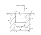
図1から図4において、本例の薄板金属の孔明け装置1は、油圧ラム等により昇降される上型ホルダ2と、上型ホルダ2に固着された押圧板3と、上型ホルダ2に弾性部材4を介して吊り下げられている押圧パッド5と、押圧パッド5にボルト6等を介して固着されたパンチユニットとして構成されたパンチホルダ7と、孔明け加工が施される薄板金属8が載置される下型9と、下型9に埋設されたダイス10とを具備している。
1 to 4, the thin plate metal drilling device 1 of this example includes an upper mold holder 2 that is lifted and lowered by a hydraulic ram, a
パンチホルダ7は、押圧パッド5にボルト6等を介して固着された円筒状のケース11と、ケース11に上下方向に摺動自在に装着された円筒状のスライダ12と、スライダ12内に上下方向に摺動自在に装着されたパンチ13と、スライダ12内に配されていると共にパンチ13を介してスライダ12を上方向に弾性的に付勢してパンチ13及びスライダ12を初期位置に復帰させるコイルばね14を具備した復帰手段と、パンチ13の上下方向の移動を案内するようにケース11に設けられた滑り案内部材15とを具備している。
The
スライダ12は、凹所21を具備しており、コイルばね14の弾性力によってケース11から抜け出さないように、ケース11に固着された抜け止めピン22に凹所21において係合するようになっており、上型ホルダ2の下降において押圧板3により下方に押圧されるようになっている。
The
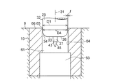
薄板金属8の孔明け用のパンチ13は、円柱状のパンチ本体25と、パンチ本体25の一方の端面である円形端面26に一体的に設けられた突起27と、パンチ本体25の他方の端面である円形端面28に一体的に設けられた鍔29とを具備している。
The
パンチ本体25は、軸心31に平行に伸びた円筒面32と、軸心31に直交して伸びた円環状面33と、円環状面33の外縁から円筒面32の外縁まで伸びる湾曲面34とを具備しており、パンチ本体25の直径D1(=2×r1)は、1mmから25mm、1mmから10mm又は1mmから5mmの範囲であり、湾曲面34の曲率半径r2は、0.1mmから5mmの範囲である。
The
突起27は、パンチ本体25の一方の円形端面26に、当該円形端面26と同心に配されていると共に当該円形端面26の直径D1よりも小さな直径D3(=2×r3)を有する円形底面41及び円形頂面42をもって当該円形底面41で一体的に設けられた高さhの円柱状部43と、円柱状部43の円形頂面42に、当該円形頂面42と同心に配されていると共に当該円形頂面42の直径D3と同じ直径を有する円形底面44をもって当該円形底面44で一体的に設けられた円錐状部45とを具備しており、円柱状部43の円形底面41は、パンチ本体25の円環状面33で囲繞されている。
The
以上のパンチ13において、パンチ本体25の半径をr1(=D1×1/2)、湾曲面34の曲率半径をr2、円柱状部43の半径をr3(=D3×1/2)、円柱状部43の高さをh、孔明けすべき薄板金属8の板厚をtとした場合、r3<r1−r2であって、h>t+r3である。
In the
コイルばね14は、一端では鍔29に他端では滑り案内部材15のフランジ部51に当接しており、滑り案内部材15は、フランジ部51に加えてフランジ部51と一体であると共にケース11の孔52において当該ケース11に嵌装されている円筒部53を有しており、円筒部53の内周面においてパンチ13のパンチ本体25の下端部を摺動自在に案内支持している。
The
ダイス10は、パンチ13が挿入される円孔61と、円孔61と連続していると共に円孔61よりも大径であってパンチ屑62(図8参照)を排出する円孔63とを有しており、円形端面26の直径D1に対する円孔61の直径D4の比D1/D4は0.80以上であって、孔明けすべき薄板金属8の厚みをtとすると、円形端面26の半径r1(=D1×1/2)とダイス10の円孔61の半径r4(=D4×1/2)との差(クリアランス)fは0.15t以上であって2mm以下である。円孔61は、ダイス10の円筒状内面64で規定されており、円筒状内面64の一方の円環状縁65は、円筒状内面64と円筒状内面64に直交するダイス10の一方の円環状の端面66との交差縁で規定されて直角縁となっている。
The
以上の孔明け装置1では、上型ホルダ2の下降と共に押圧板3、押圧パッド5及びパンチホルダ7が下降されると、下型9に載置された薄板金属8が押圧パッド5により押圧されて下型9と押圧パッド5との間に挟まれて固定されると共にスライダ12が押圧板3に押され、スライダ12の押下と共にパンチ13が下降され、パンチ13の下降で、図5に示すように突起27の円錐状部45により、そして続いて円柱状部43により薄板金属8に突き破り孔71が明けられ、突き破り孔71に挿入された突起27の円柱状部43で薄板金属8の移動が規制された状態で図6に示すように更にパンチ13が下降されてダイス10の円孔61にパンチ13のパンチ本体25が挿入されると、円形端面26の円環状面33に接触した薄板金属8が当該円環状面33に押されてパンチ本体25の下降と共に下降され、この下降において、円形端面26の湾曲面34と円孔61の一端を規定するダイス10の円筒状内面64の円環状縁65とでその間にある薄板金属8が引っ張られて伸ばされて、その後、ダイス10の円環状縁65側で薄板金属8は、図7に示すように引き千切られて破断され、薄板金属8のダイス10の円環状縁65側での破断後、図8に示すようにパンチ13は上昇される一方、パンチ屑62は円孔63を通って排出され、こうして薄板金属8には貫通孔72が形成される。
In the drilling device 1 described above, when the
ところで、パンチ13では、突起27がパンチ本体25の一方の円環状面33に円形底面41及び円形頂面42をもって一体的に設けられた円柱状部43を有しているために、突起27の円錐状部45の先端の円錐角を十分な強度及び耐久性を得られるように大きくすると共に突起27による突き破り孔71の形成後における突き破り孔71からの突起27の抜け出し(図9に従来例での突き破り孔71からの突起27の抜け出し示す)を防止するように突起27の全体を高くしても、突起27の円柱状部43の円形底面41を囲繞していると共に軸心31に直交して伸びた円環状面33を十分な広さをもってパンチ本体25の円形端面26に確保でき、而して、パンチ本体25と協同してダイス10の円孔61の一端を規定するダイス10の円筒状内面64の円環状縁65の周りで薄板金属8を確実に破断させて薄板金属8に貫通孔72を精度よく形成できる。
By the way, in the
しかも、湾曲面34が0.1mmから5mmの曲率半径r2をもっているために、バリの原因となる剪断の効果を減じて薄板金属8をより良好に引っ張り破断させることができ、その上、比D1/D4が0.80以上であって、差fが0.15t以上であるために、多少の剪断に加えて主に引っ張り破断を生じさせて効果的に薄板金属8に貫通孔72を形成することができる。
Moreover, since the
孔明け装置1では、パンチ13を上下動させて貫通孔72を形成したが、パンチ13を斜めに移動させて薄板金属8の傾斜部に貫通孔72を形成するようにしてもよい。
In the punching device 1, the
1 孔明け装置
2 上型ホルダ
3 押圧板
4 弾性部材
5 押圧パッド
7 パンチホルダ
8 薄板金属
9 下型
10 ダイス
13 パンチ
25 パンチ本体
26 円形端面
27 突起
28 円形端面
29 鍔
DESCRIPTION OF SYMBOLS 1 Drilling device 2
Claims (2)
Priority Applications (1)
| Application Number | Priority Date | Filing Date | Title |
|---|---|---|---|
| JP2012176543A JP5678933B2 (en) | 2012-08-08 | 2012-08-08 | Sheet metal drilling device having punch for punching sheet metal |
Applications Claiming Priority (1)
| Application Number | Priority Date | Filing Date | Title |
|---|---|---|---|
| JP2012176543A JP5678933B2 (en) | 2012-08-08 | 2012-08-08 | Sheet metal drilling device having punch for punching sheet metal |
Related Parent Applications (1)
| Application Number | Title | Priority Date | Filing Date |
|---|---|---|---|
| JP2006343597A Division JP2008155216A (en) | 2006-12-20 | 2006-12-20 | Punch for punching sheet metal, sheet metal punching device provided with the punch, and method therefor |
Publications (3)
| Publication Number | Publication Date |
|---|---|
| JP2012210662A JP2012210662A (en) | 2012-11-01 |
| JP2012210662A5 JP2012210662A5 (en) | 2013-07-04 |
| JP5678933B2 true JP5678933B2 (en) | 2015-03-04 |
Family
ID=47265081
Family Applications (1)
| Application Number | Title | Priority Date | Filing Date |
|---|---|---|---|
| JP2012176543A Active JP5678933B2 (en) | 2012-08-08 | 2012-08-08 | Sheet metal drilling device having punch for punching sheet metal |
Country Status (1)
| Country | Link |
|---|---|
| JP (1) | JP5678933B2 (en) |
Cited By (1)
| Publication number | Priority date | Publication date | Assignee | Title |
|---|---|---|---|---|
| CN109243800A (en) * | 2018-10-20 | 2019-01-18 | 天水二三电器有限公司 | A kind of processing method of moving armature and moving armature center dome platform |
Families Citing this family (1)
| Publication number | Priority date | Publication date | Assignee | Title |
|---|---|---|---|---|
| FR3098444B1 (en) * | 2019-07-08 | 2021-10-01 | Soc Internationale Pour Le Commerce Et Lindustrie | A method of reinforcing a panel and a method of manufacturing a composite panel implementing such a method |
Family Cites Families (6)
| Publication number | Priority date | Publication date | Assignee | Title |
|---|---|---|---|---|
| JPH0395123U (en) * | 1990-01-08 | 1991-09-27 | ||
| JP3372315B2 (en) * | 1992-12-07 | 2003-02-04 | 富士写真フイルム株式会社 | Perforator |
| JPH0654424U (en) * | 1992-12-25 | 1994-07-26 | 日野自動車工業株式会社 | Countersink punch |
| JP4556326B2 (en) * | 2000-11-19 | 2010-10-06 | 株式会社ワンズ | Press punching method and press die for sheet metal |
| ES2338327T3 (en) * | 2003-04-30 | 2010-05-06 | Ones Co., Ltd. | PUNCH FOR SLIM METAL SHEET AND PUNCH DEVICE FOR SLIM METALLIC SHEET WITH SUCH PUNCH. |
| JP4775782B2 (en) * | 2004-03-17 | 2011-09-21 | 株式会社ワンズ | Drilling device |
-
2012
- 2012-08-08 JP JP2012176543A patent/JP5678933B2/en active Active
Cited By (1)
| Publication number | Priority date | Publication date | Assignee | Title |
|---|---|---|---|---|
| CN109243800A (en) * | 2018-10-20 | 2019-01-18 | 天水二三电器有限公司 | A kind of processing method of moving armature and moving armature center dome platform |
Also Published As
| Publication number | Publication date |
|---|---|
| JP2012210662A (en) | 2012-11-01 |
Similar Documents
| Publication | Publication Date | Title |
|---|---|---|
| JP4556870B2 (en) | Punch for punching sheet metal and punching apparatus for sheet metal provided with this punch | |
| CA2686479C (en) | Die for punching sheet metal and sheet metal punching apparatus having the die | |
| JP2008155216A (en) | Punch for punching sheet metal, sheet metal punching device provided with the punch, and method therefor | |
| WO2009153833A1 (en) | Drilling punch for sheet metal, drilling device for sheet metal including the punch, and its method | |
| JP5678933B2 (en) | Sheet metal drilling device having punch for punching sheet metal | |
| JP5794611B2 (en) | Punch for sheet metal drilling and apparatus for drilling sheet metal using the same | |
| JP2009279642A (en) | Burring metallic mold, burring punch, and burring method | |
| JP4985174B2 (en) | Sheet metal drilling device and method | |
| JP4830759B2 (en) | Punch for punching sheet metal, punching apparatus for sheet metal provided with the punch, and method for punching sheet metal | |
| JP5967180B2 (en) | Punch for sheet metal drilling and apparatus for drilling sheet metal using the same | |
| JP5577666B2 (en) | Sheet metal drilling device and die used therefor | |
| JP5799992B2 (en) | Sheet metal drilling device | |
| JP5459230B2 (en) | Sheet metal drilling device and method | |
| JP6583366B2 (en) | Punch for punching, die for drilling with the punch, and drilling method using the punch | |
| KR200436122Y1 (en) | Press Mold of Piercing Punch | |
| JP5857446B2 (en) | Punch unit for punching thin metal plate and thin metal punching device equipped with this punch unit | |
| JP6664629B1 (en) | Mold die | |
| JP2012210662A5 (en) | ||
| CN103350141B (en) | For the boring drift of metallic plate, the metallic plate rig comprising this drift and method thereof |
Legal Events
| Date | Code | Title | Description |
|---|---|---|---|
| A521 | Request for written amendment filed |
Free format text: JAPANESE INTERMEDIATE CODE: A523 Effective date: 20120907 |
|
| A621 | Written request for application examination |
Free format text: JAPANESE INTERMEDIATE CODE: A621 Effective date: 20120907 |
|
| RD01 | Notification of change of attorney |
Free format text: JAPANESE INTERMEDIATE CODE: A7426 Effective date: 20120924 |
|
| A521 | Request for written amendment filed |
Free format text: JAPANESE INTERMEDIATE CODE: A821 Effective date: 20120924 |
|
| A521 | Request for written amendment filed |
Free format text: JAPANESE INTERMEDIATE CODE: A523 Effective date: 20130522 |
|
| A977 | Report on retrieval |
Free format text: JAPANESE INTERMEDIATE CODE: A971007 Effective date: 20131011 |
|
| A131 | Notification of reasons for refusal |
Free format text: JAPANESE INTERMEDIATE CODE: A131 Effective date: 20131022 |
|
| A521 | Request for written amendment filed |
Free format text: JAPANESE INTERMEDIATE CODE: A523 Effective date: 20131224 |
|
| A131 | Notification of reasons for refusal |
Free format text: JAPANESE INTERMEDIATE CODE: A131 Effective date: 20140408 |
|
| A521 | Request for written amendment filed |
Free format text: JAPANESE INTERMEDIATE CODE: A523 Effective date: 20140605 |
|
| TRDD | Decision of grant or rejection written | ||
| A01 | Written decision to grant a patent or to grant a registration (utility model) |
Free format text: JAPANESE INTERMEDIATE CODE: A01 Effective date: 20141209 |
|
| A61 | First payment of annual fees (during grant procedure) |
Free format text: JAPANESE INTERMEDIATE CODE: A61 Effective date: 20141222 |
|
| R150 | Certificate of patent or registration of utility model |
Ref document number: 5678933 Country of ref document: JP Free format text: JAPANESE INTERMEDIATE CODE: R150 |
|
| R250 | Receipt of annual fees |
Free format text: JAPANESE INTERMEDIATE CODE: R250 |
|
| R250 | Receipt of annual fees |
Free format text: JAPANESE INTERMEDIATE CODE: R250 |
|
| R250 | Receipt of annual fees |
Free format text: JAPANESE INTERMEDIATE CODE: R250 |
|
| R250 | Receipt of annual fees |
Free format text: JAPANESE INTERMEDIATE CODE: R250 |
|
| R250 | Receipt of annual fees |
Free format text: JAPANESE INTERMEDIATE CODE: R250 |
|
| R250 | Receipt of annual fees |
Free format text: JAPANESE INTERMEDIATE CODE: R250 |
|
| R250 | Receipt of annual fees |
Free format text: JAPANESE INTERMEDIATE CODE: R250 |