JP5678141B2 - Transmission devices and sensor systems - Google Patents
Transmission devices and sensor systems Download PDFInfo
- Publication number
- JP5678141B2 JP5678141B2 JP2013154523A JP2013154523A JP5678141B2 JP 5678141 B2 JP5678141 B2 JP 5678141B2 JP 2013154523 A JP2013154523 A JP 2013154523A JP 2013154523 A JP2013154523 A JP 2013154523A JP 5678141 B2 JP5678141 B2 JP 5678141B2
- Authority
- JP
- Japan
- Prior art keywords
- measurement signal
- ended
- signal
- differential
- measurement
- Prior art date
- Legal status (The legal status is an assumption and is not a legal conclusion. Google has not performed a legal analysis and makes no representation as to the accuracy of the status listed.)
- Expired - Fee Related
Links
Images


Classifications
-
- G—PHYSICS
- G06—COMPUTING; CALCULATING OR COUNTING
- G06G—ANALOGUE COMPUTERS
- G06G7/00—Devices in which the computing operation is performed by varying electric or magnetic quantities
- G06G7/12—Arrangements for performing computing operations, e.g. operational amplifiers
-
- G—PHYSICS
- G01—MEASURING; TESTING
- G01D—MEASURING NOT SPECIALLY ADAPTED FOR A SPECIFIC VARIABLE; ARRANGEMENTS FOR MEASURING TWO OR MORE VARIABLES NOT COVERED IN A SINGLE OTHER SUBCLASS; TARIFF METERING APPARATUS; MEASURING OR TESTING NOT OTHERWISE PROVIDED FOR
- G01D1/00—Measuring arrangements giving results other than momentary value of variable, of general application
- G01D1/10—Measuring arrangements giving results other than momentary value of variable, of general application giving differentiated values
-
- H—ELECTRICITY
- H04—ELECTRIC COMMUNICATION TECHNIQUE
- H04Q—SELECTING
- H04Q9/00—Arrangements in telecontrol or telemetry systems for selectively calling a substation from a main station, in which substation desired apparatus is selected for applying a control signal thereto or for obtaining measured values therefrom
-
- H—ELECTRICITY
- H04—ELECTRIC COMMUNICATION TECHNIQUE
- H04Q—SELECTING
- H04Q2209/00—Arrangements in telecontrol or telemetry systems
- H04Q2209/80—Arrangements in the sub-station, i.e. sensing device
- H04Q2209/84—Measuring functions
Description
本発明の実施例は、2つの電気インパルス測定信号の伝送デバイスに関し、また、センサーシステムに関する。 Embodiments of the present invention relate to a device for transmitting two electrical impulse measurement signals and to a sensor system.
センサーシステムは、たとえば医療技術のガンマ線検出の陽電子放射断層撮影システムの実施例のために、フォトダイオードアレイまたはピクセルアレイとすることができる。ピクセルアレイまたは一般にあらゆるセンサーエレメントのあらゆるピクセルは、例えば少ない発生率または少ないパルスの結果、測定された量または値を記録するときに、測定信号を出力する。この種のアプリケーションで、測定信号は、一般的に、所謂、シングルエンド測定信号である。シングルエンド測定信号は、例えば、決定された基準信号に関する電流信号のように、例えば、大量の信号(大量の導体に適用された)のような電気信号であり、そして、それが1つの単一信号導体を用いて送信することができる。 The sensor system can be a photodiode array or a pixel array, for example for embodiments of positron emission tomography systems for medical technology gamma ray detection. Every pixel of the pixel array or generally every sensor element outputs a measurement signal when recording a measured quantity or value, for example as a result of a low incidence or a low pulse. In this type of application, the measurement signal is generally a so-called single-ended measurement signal. A single-ended measurement signal is, for example, an electrical signal such as a large amount of signal (applied to a large number of conductors), such as a current signal with respect to a determined reference signal, and it is a single signal The signal conductor can be used for transmission.
高い集積密度の集積回路については、特に、アナログおよびデジタル機能が同時に実現される場合に、シングルエンド測定信号は、個々の回路ブロックとの間に、そして、このように個々のチャネルとの間にしばしば漏話に至る。アナログ回路技術において、この種の漏話は、差動測定信号を用いて減らすことができるかまたは防止することができる。差動測定信号は、2つの信号導体を用いて測定された量についてのそれぞれの信号情報を送信する。そこにおいて、実際の信号は、電圧差または第1の信号部分(第1の信号導体を介して送信される)および第2の信号部分(第2の信号導体を介して送信される)の間の電流差である。例えば、第1および第2の信号部分の平均値は、差動測定信号を干渉に非常に抵抗するようにする外部の干渉が原因で変化する場合、それはここ(信号情報に)の電圧差に影響を及ぼさない。上述のセンサー・アプリケーションのこれらの利点を用いるために、しばしば、個々のセンサーエレメントのシングルエンド測定信号は、差動測定信号に変換される。例えばシングルエンド差動コンバータ(明示的な回路)のような変換のために、異なる回路または部材がある。あるいは、また、差動アンプは、信号処理中のノイズに関与して、総エネルギー要求を増加させる少なくとも2つの入力トランジスターを典型的に含んで、この点で用いられてもよい。 For high integration density integrated circuits, especially when analog and digital functions are implemented simultaneously, single-ended measurement signals can be transferred between individual circuit blocks and thus between individual channels. Often leads to crosstalk. In analog circuit technology, this type of crosstalk can be reduced or prevented using differential measurement signals. The differential measurement signal transmits respective signal information about the quantity measured using the two signal conductors. There, the actual signal is between the voltage difference or the first signal part (sent via the first signal conductor) and the second signal part (sent via the second signal conductor). Current difference. For example, if the average value of the first and second signal portions changes due to external interference that makes the differential measurement signal very resistant to interference, it is here the voltage difference (in the signal information) Has no effect. In order to use these advantages of the sensor applications described above, often single-ended measurement signals of individual sensor elements are converted into differential measurement signals. There are different circuits or components for conversion, for example a single-ended differential converter (explicit circuit). Alternatively, the differential amplifier may also be used in this regard, typically including at least two input transistors that contribute to noise during signal processing and increase the total energy requirement.
したがって、本発明の目的は、干渉、エネルギー消費、スペース必要条件および製造コストに対する抵抗のために改善された妥協策を提示する信号伝送に対するコンセプトを提供することである。 Accordingly, it is an object of the present invention to provide a concept for signal transmission that presents an improved compromise due to resistance to interference, energy consumption, space requirements and manufacturing costs.
本発明の目的は、請求項1に記載の伝送デバイスによって、請求項14に記載のセンサーシステムによって、請求項15に記載のシングルエンド差動コンバータの利用によって、そして、請求項16に記載の方法によって、解決される。
The object of the present invention is by the transmission device according to claim 1, by the sensor system according to
本発明の実施例は、第1および第2の測定信号入力、差動測定信号出力および信号コンバータを有する2つの電気インパルス測定信号のための伝送デバイスを提供する。第1の測定信号入力は、第1のシングルエンド測定信号を受信することに使われて役に立つ。その一方で、第2の測定信号入力は、第2のシングルエンド測定信号を受信することに使われて役に立つ。第1のシングルエンド測定信号あるいは第2のシングルエンド測定信号を複合差動測定信号に変換し、かつ差動測定信号出力で同じことを提供するために、シングルエンド測定信号の内の1つを受信する場合、信号コンバータが実施される。そこでは、差動測定信号は第1のシングルエンド測定信号に割り付けることができる第1の差部分、および、第2のシングルエンド測定信号に割り付けることができる第2の差部分を含む。 Embodiments of the present invention provide a transmission device for two electrical impulse measurement signals having first and second measurement signal inputs, a differential measurement signal output and a signal converter. The first measurement signal input is used to receive a first single-ended measurement signal. On the other hand, the second measurement signal input is useful for receiving a second single-ended measurement signal. In order to convert the first single-ended measurement signal or the second single-ended measurement signal into a composite differential measurement signal and provide the same at the differential measurement signal output, one of the single-ended measurement signals is When receiving, a signal converter is implemented. There, the differential measurement signal includes a first difference portion that can be assigned to the first single-ended measurement signal and a second difference portion that can be assigned to the second single-ended measurement signal.
本発明の実施例は、熟慮したアプリケーションで、特に、非常に短い信号、例えば、100nsの持続時間を有するパルス信号が検出される発見に基づく。そこでは信号の繰り返し数は、例えば毎秒6回と低い。したがって、2つのシングルエンド測定信号が同時に送信される可能性は低い。この発見は、それが複合差動測定信号として異なる時間に発生する2つのセンサーエレメントの2つのシングルエンド測定信号を送信するという事実による発明の伝送デバイスによって利用される。差動測定信号において、第1のシングルエンド測定信号かそれとも第2のシングルエンド測定信号に割り付けることができる同じ部分は、それらの両極性について識別することができる。2つのシングルエンド測定信号が干渉のない差動測定信号として伝送デバイスを用いて送信され得ることは、ここで有利である。同じデバイスを経由した2つのシングルエンド測定信号の(連続の)伝送によって、伝送デバイスの数およびこのようにセンサーシステムの電流消費は、例えば半分に減らすことができる。さらに、伝送デバイスの数およびこのように利用された電気的な部材の数が減らされるとともに、多くの製造コストもまた減らされる。 Embodiments of the present invention are based on the discovery that very sensitive signals, for example pulse signals having a duration of 100 ns, are detected in contemplating applications. There, the number of signal repetitions is as low as, for example, 6 times per second. Therefore, it is unlikely that two single-ended measurement signals are transmitted simultaneously. This discovery is exploited by the inventive transmission device due to the fact that it transmits two single-ended measurement signals of two sensor elements that occur at different times as a composite differential measurement signal. In the differential measurement signal, the same part that can be assigned to the first single-ended measurement signal or the second single-ended measurement signal can be identified for their polarity. It is advantageous here that two single-ended measurement signals can be transmitted using the transmission device as differential measurement signals without interference. By (continuous) transmission of two single-ended measurement signals via the same device, the number of transmission devices and thus the current consumption of the sensor system can be reduced, for example, by half. In addition, the number of transmission devices and the number of electrical components utilized in this way are reduced, and many manufacturing costs are also reduced.
さらなる実施例によれば、差動測定信号の2つの異なる両極性のため第1のシングルエンド測定信号に関する差動測定信号の異なる部分の被譲渡性が残るように、例えば、差動アンプまたは単純なシングルエンド差動コンバータを含む伝送デバイスによって、単極シングルエンド測定信号の内の1つは、単極シングルエンド測定信号を有するその他に関して逆にされる。 According to a further embodiment, for example, a differential amplifier or a simple one can remain so that different parts of the differential measurement signal with respect to the first single-ended measurement signal remain due to the two different polarities of the differential measurement signal. With a transmission device that includes a single-ended differential converter, one of the single-pole single-ended measurement signals is reversed with respect to the other having a single-pole single-ended measurement signal.
さらなる実施例は、複数のセンサーエレメントおよび上記の伝送デバイスの内の少なくとも2つを備えているセンサーシステムを提供する。ここで、第1のセンサーエレメントは、第1の伝送デバイスの2つの測定信号入力の最初の1つに接続される。そして、第2のセンサーエレメントは、第2の伝送デバイスの2つの測定信号入力の最初の1つに接続される。そこにおいて、第1のセンサーエレメントに隣接して配置されない第3のセンサーエレメントは、第1の伝送デバイスの2つの測定信号入力の別の1つに接続される。
この種のインタリーブ装置によって、例えば近くにあるかまたは隣接的な2つのセンサーエレメントの漏話のような影響は測定され得る。
A further embodiment provides a sensor system comprising a plurality of sensor elements and at least two of the transmission devices described above. Here, the first sensor element is connected to the first one of the two measurement signal inputs of the first transmission device. The second sensor element is then connected to the first one of the two measurement signal inputs of the second transmission device. There, a third sensor element that is not arranged adjacent to the first sensor element is connected to another one of the two measurement signal inputs of the first transmission device.
With this type of interleaving device, effects such as crosstalk between two sensor elements in the vicinity or adjacent to each other can be measured.
さらなる実施例は、2つの電気インパルス測定信号の伝送方法を提供する。方法は、第1の測定信号入力によって第1のシングルエンド測定信号を受信して、第2の測定信号入力によって第2のシングルエンド測定信号を受信して、第1のシングルエンド測定信号か第2のシングルエンド測定信号を複合差動測定信号に変換して、差動測定信号出力で差動測定信号を出力するステップを含む。ここで、差動測定信号は、第1のシングルエンド測定信号に割り当てることができる第1の差部分および第2のシングルエンド測定信号に割り当てることができる第2の差部分を含む。全般的に見て、記載されている方法で、伝送品質は、干渉(差動伝送)に関して、より強健な伝送方法の使用によって、また、例えばノイズのような干渉信号を減らすことによって、および、例えばトランジスターのような干渉信号を引き起こす活発な要素を減らすことによって、一方では増加される。 A further embodiment provides a method for transmitting two electrical impulse measurement signals. The method receives a first single-ended measurement signal by a first measurement signal input, receives a second single-ended measurement signal by a second measurement signal input, Converting two single-ended measurement signals into a composite differential measurement signal and outputting a differential measurement signal at a differential measurement signal output. Here, the differential measurement signal includes a first difference portion that can be assigned to the first single-ended measurement signal and a second difference portion that can be assigned to the second single-ended measurement signal. Overall, in the manner described, the transmission quality is improved by using a more robust transmission method with respect to interference (differential transmission) and by reducing interference signals such as noise, and On the one hand, it is increased by reducing active elements that cause interference signals, such as transistors.
以下において、本発明の実施例は、添付の図面を参照して、さらに詳細に説明される。 In the following, embodiments of the present invention will be described in more detail with reference to the accompanying drawings.
本発明の実施例が以下の図を参照してさらに詳細に説明される前に、同じことの説明が交換可能であるかまたは相互に適用されることができるように、同等のものあるいは一見して同じような要素または構造には、同じ参照数字が提供されているということを特に言及するものである。 Before the embodiments of the present invention are described in more detail with reference to the following figures, the same or seemingly equivalent, so that the same description can be interchanged or applied to each other. It is specifically noted that like elements or structures are provided with the same reference numerals.
図1Aは、第1の測定信号入力14により入力量または変数または値としてシングルエンド測定信号12を受信して、同じものを差動測定信号16に変換して、2つの信号導体18aおよび18bを有する差動測定信号出力18で同じものを提供するために行うシングルエンド差動コンバータ10を示す。この点で、シングルエンド測定信号12は、例えば、基準信号20に関して適用される電圧信号または電流信号である点に留意する必要がある。基準信号20は、例えば、シングルエンド差動コンバータの基準信号入力22により受け取ることができる大量の信号でもよい。個々の信号(シングルエンド測定信号12、基準信号20および差動測定信号16)は、図1Bを参照してさらに詳細に説明される。
FIG. 1A receives a single-
図1Bは、時間とともにプロットされる2つの略図を示す。そこにおいて、1番目の略図は、一定の基準信号20に関するシングルエンド測定信号12を例示する。そして、2番目の略図は、結果として生じる差動測定信号16を例示する。両方の略図のために、それぞれの測定された値は、例えば、電流または電圧を表す。
FIG. 1B shows two schematics plotted over time. There, the first schematic illustrates a single-ended
1番目の略図において、シングルエンド測定信号12および基準信号20の違いは、実際の信号情報である。シングルエンド測定信号12は、正弦波形状に形成され、少なくとも1つの極大値12max および1つの極小値12min を含む。上記した図示のシングルエンド差動コンバータ10によって、シングルエンド測定信号12は、2つの信号部分16aおよび16bを含む差動測定信号16に変換される。そして、各々が差動測定信号出力18の別々の信号導体18aまたは18bにより送信される。2つの信号形式の変換において、一方では、第1の信号導体18aに対するシングルエンド測定信号12の直接的な伝送および他方では、第2の信号導体18bへの同じことおよび送信の反転が実行される。そこではコモンモードリジェクションが実行される。
In the first schematic diagram, the difference between the single-ended
ここの実際の信号の情報は、第1のシングルエンド測定信号12と比較して、典型的に倍のサイズである個々の信号部分16aと16bとの違いをあらわす。さらに、差動測定法信号16は、信号部分16aが信号部分16b(16a−16b>0)より大きい場合、極大値16max を含み、信号部分16bが信号部分16a(16a−16b<0)より大きい場合、極小値16min を含む。極大値16max および極小値16min の位置は、時間軸上で極大値12max および極小値12min のシングルエンド測定信号12の位置に対応する。2番目の略図に関して見られるように、個別の信号導体18aあるいは18bの中で送信される信号部分16aおよび16bの両方は、対称的であるか、あるいは互いに関して平衡を保たれる。2つの信号部分16aおよび16bの左右対称は、シングルエンド差動コンバータ10によって、シングルエンド測定信号12のコモンモード部分が変換で最小化されるかまたは除去されるという事実から生じる。2つの信号導体18aおよび18bに対する外部の干渉が実質的に互いに相殺するので、この種の信号伝送は干渉に関して非常に寛容である。原理は、信号部分16aおよび16bの両方に作用する干渉が個々の信号部分16aあるいは16bを変えるということである。したがって、2つの信号部分16aおよび16bの間の差ではなく平均値である。
The actual signal information here represents the differences between the
図2Aは、例えば演算増幅器等の差動アンプ10aを含む差動シングルエンド変換用のさらなる装置を示す。差動アンプ10aは、一定の参照変数20に関して基準信号入力22に適用されるシングルエンド測定信号12を受信するための第1の測定信号入力14を含む。このように、シングルエンド測定信号12は、差動信号として基準信号20と共に処理される。
FIG. 2A shows a further apparatus for differential single-ended conversion including a
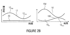
1番目の略図において、図2Bは、時間とともにプロットされる一定の基準信号20と共に、再び、シングルエンド測定信号12を示す。図1Bとの類似では、シングルエンド測定信号12は、極大値12max および極小値12min を含む。差動アンプ10aは、入力14および22の2つの信号12および20間の差を増幅するために実施される。そこにおいて、ここの基準信号入力22は反転している。したがって、差動アンプ10aによって、差動測定信号16´は、所望の差動モード信号を含む差動出力18で提供される。
In the first schematic, FIG. 2B again shows the single-ended
差異信号16´は、さらに、不要なコモンモード信号を含むとともに、2番目の略図の中で説明されるように、同じことは対称的ではない。このように、コモンモード信号(基準信号20を参照)を抑制するかまたは拒絶するために形成されるコモンモードリジェクションは実行される。 差動測定信号16´は、次々に、第1の信号部分16aおよび第2の信号部分16bを含み、そこでは、実際の信号情報は、絶対値(つまり、12>20の場合、16a´>16b´)として、2つの信号部分16a´および16b´間の差に含まれる。したがって、2つの信号部分16a´および16b´間の差は、極大値12max がシングルエンド測定信号12に存在するときに最大となり、 極小値12min がシングルエンド測定信号12に存在するときに最小となる。差動測定信号16´において、これらの2つの極大値あるいは極小値は、参照数字16max および16min によって示される。入力信号(12<20、図示せず)の反転された極性については、差異信号16´の極性も反転される(つまり、16a´<16b´)。
The difference signal 16 'further includes an unwanted common mode signal and the same is not symmetric as explained in the second schematic. In this way, common mode rejection formed to suppress or reject common mode signals (see reference signal 20) is performed. The
図1Aおよび2Aの中で説明されたシングルエンド差動変換用の2つのデバイス10および10aは、 一般的に1つのセンサー当たり1回必要であり、それは一方では経常消費を、そして他方では、回路の空間的必要条件を増加させる。したがって、デバイスは、以下に述べられるように、縮小された経常消費および空間的必要条件と同じ機能性を可能にする。
The two
送信されるシングルエンド測定信号が単極性パルス信号であるとここで仮定されている。すなわち、短期間(例えば、10Hzの周波数において200nsより短い)の間のみ生じる信号、および1つだけの肯定的または1つの否定的な信号の変更あるいはたった1つの極性を備えた信号の変更をここでは含む。この種の単極パルス信号は、熟慮した適用、すなわち、陽電子放射断層撮影システム(PET)に、または、単一光子放出コンピュータ断層撮影システム(SPECT)に用いられて典型的である。 It is assumed here that the single-ended measurement signal transmitted is a unipolar pulse signal. That is, change signals that occur only for short periods (eg, shorter than 200 ns at a frequency of 10 Hz) and only one positive or one negative signal or a signal with only one polarity. In including. This type of monopolar pulse signal is typical for use in deliberate applications, ie positron emission tomography systems (PET) or single photon emission computed tomography systems (SPECT).
図3Aは、第1の測定信号入力14、第2の(反転された)測定信号入力15および2つの信号導体端子18aおよび18bを有する差動測定信号出力18を含む信号変換器30を有する伝送デバイス29を示す。
FIG. 3A shows a transmission with a
第1の測定信号入力14によって、第1のシングルエンド測定信号12aは受信されることができ、また、第2の測定信号入力15によって、第2のシングルエンド測定信号12bは受信されることができる。2つの受信されたシングルエンド測定信号12aおよび12bは、1番目の略図(時間とともにプロットされた)の図3Bに例示されている。これから分かるように、2つのシングルエンド測定信号12aおよび12bは、異なる時間に発生して、各々短い時間分(パルス特性)を有する。その結果、2つのシングルエンド測定信号12aおよび12bを同時に、(すなわち、2つのセンサー中の2つの独立事象の結果として、)受信する可能性は低い。1番目の略図は、シングルエンド測定信号12aおよび12bの各々は、(測定変数を検出するときに)1つの方向にのみベースラインからコントロールされるように、2つのシングルエンド測定信号12aおよび12bが単極であることをさらに示す。それぞれの測定された値(放射イベント)の検出は、ベースラインに関して極大値に帰着するとともに、これらのベースラインまたは基本信号レベルは一定であり、例えば、基礎/静止センサー電流から生じる。すなわち、基本信号レベル、すなわち、極小値、に関して負である負のシングルエンド測定信号12aあるいは12bもまた放射イベントから生じ得る。したがって、その結果、差動測定信号32の極性も反転される(すなわち、16a´<16b´)。個々のセンサーエレメントのベースセンサーの電流レベルの高さは、わずかに変化する点に留意する必要がある。
The first single-ended
信号変換器30は、2つのシングルエンド測定信号12aおよび12bを差動測定信号に変換するために実行される。同じことを組み合わせて、したがって1つの伝送チャネルにこのように2つのシングルエンド測定信号12aおよび12bのバンドリングを獲得するために結合された複合差動測定信号32としての差動測定信号出力18で同じことを提供する。同じことの単極の特徴により、シングルエンド測定信号12aおよび12bを変換する場合、差動信号エリアの半分だけが用いられる。それぞれのシングルエンド測定信号12aおよび12bに関して、個々の差の部分の被譲渡性を維持するために、2つのシングルエンド測定信号12aおよび12bを組み合わせる場合、この特性が利用され得る。この点で、例えば、2つのシングルエンド測定信号12aおよび12bがそれらの極性によって異なるように、第2のシングルエンド測定信号12bは反転することができる。
The
差動測定信号32をその2つの信号部分32aおよび32bで例示する図3Bの第2の略図を考慮するとき、この原理は明白になる。複合差動測定信号32は、差動形式のシングルエンド測定信号12aおよび12bを含む。つまり、そこにおいて、2つの信号部分32aおよび32bの差は、第1のシングルエンド測定信号12aの極大値のときに、そして、第2のシングルエンド測定信号12bの最大のときに最大値を含む。2つの信号部分32aあるいは32bを別々に考慮する場合、第1のシングルエンド測定信号12aの最大の時に第1の信号部分32aが極大値を含み、 第2のシングルエンド測定信号12bの最大の時に極小値を含むことが理解され得る。反対に、第1のシングルエンド測定信号12が最大の時に第2の信号部分32bは、極小値を含み、第2のシングルエンド測定信号12bが局所極大の時に極大値を含む。その限りにおいて、2つの信号部分32aおよび32bの絶対比較によって、2つのシングルエンド測定信号12aおよび12bは区別可能である。言いかえれば、これは、第1のシングルエンド測定信号12a(それは第1の測定信号入力14によって受信される)が、差動測定信号32aに帰着することを意味する。第1の信号部分32aは第2の信号部分32bより大きく、一方で、第2のシングルエンド測定信号12b(それは第2の測定信号入力15によって受信される)が、差動測定信号32に帰着し、第2の信号部分32bが第1の信号部分32aより大きい。その限りにおいて、極性によって、差動測定信号32(したがって、第1および第2の測定信号入力14および15に接続されたセンサーエレメントにより検知されたイベントに決定される時間 )の一部は、それぞれ、イベントに明白に関連させることができる。
This principle becomes apparent when considering the second schematic diagram of FIG. 3B illustrating the
2つの図形を比較する場合、オリジナルのシングルエンド測定信号12aあるいはシングルエンド測定信号12bと比べて、差動測定信号32は、2倍高い振幅を含み、そして、それはまるで増加した干渉信号許容度(低い信号対雑音比のため)のような改良された信号品質に貢献することは明らかである。このようなわけで、さらなる実施例によれば、信号変換器30あるいは伝送デバイス29が差動測定信号32を提供するように実行され、その結果、その同じ量または大きさがシングルエンド測定信号12aまたはシングルエンド測定信号12bのn倍となる。2つのシングルエンド測定信号12aおよび12bが同時に極大値を形成するとき、この信号の振幅比は失われる場合があるかもしれないし、あるいは同時に検知されたイベントの結果として極大値をオーバーラップさせている場合があるかもしれない。これによって、2つの信号部分32aおよび32bは部分的にオーバーラップするかまたは各々を相殺する。そして、さらなる実施例によると、それはエラーが本当らしくない信号の結果として検知される事実に至る。
When comparing two graphics, the
第2の測定信号入力15および典型的には使用されたセンサーエレメントが比較可能なベースラインあるいは比較可能なアイドル信号レベルを含むという事実を反転することによって、シングルエンド測定信号12aおよび12bのコモンモード部分(基準電位20を参照)は縮小される。この点で、アイドル信号が同じである場合、コモンモード部分を完全に取り消すこと(あるいは平均化)生じる場合がある。ここの背景は、第2の反転されたシングルエンド測定信号12bが第1のシングルエンド測定信号12aに用いる基準信号を示し、その一方で第1のシングルエンド測定信号12aが、第2のシングルエンド測定信号12bに用いる基準信号を示している。2つの信号12aおよび12bが同じ種類の部材によって発生する同じ種類の信号であるとともに、2つのシングルエンド測定信号12aおよび12bは、概して、同じことあるいは同様の温度依存のパフォーマンスを有し、その結果、反転によって、温度補償は同時に起こる。
By inverting the fact that the second
以下には、信号変換器の2つの特定の具体化が記載されている。 In the following, two specific implementations of the signal converter are described.
図4Aは、差動アンプ、または、典型的に反転される第1の測定信号入力14および第2の測定信号出力15を含む演算増幅器30a、および、差動測定信号出力18を示す。さらに、差動アンプ30aは、さらに2つの供給電圧ターミナル34aおよび34bを含む。演算増幅器30aが記載されたとしても、ここでは、最小の端末構成だけが説明されることが注目され、さらに、頻繁に信号オフセットに用いられる例えばターミナルを含み得る。
FIG. 4A shows a differential amplifier or an
シングルエンド測定信号を差動測定信号に変換するように、上述したように同じことが実施されるために、この種の差動アンプ30aは、信号変換器30として機能することができる。この差動アンプ30aによって、2つのシングルエンド測定信号12aおよび12bを複合差動測定信号32に変換するために、第1のシングルエンド測定信号12aが第1の測定信号入力14によって複合され、第2の(反転された)シングルエンド測定信号12bが測定信号入力15によって複合される。その結果、差動測定信号32は差動出力18によって出力され得る。電圧供給ターミナル34aおよび34bによって、差動アンプ30aのための供給電圧が接続される点に更に言及される。そして、それによって、動作点は供給電圧のバリエーションによってセットすることができる。シングルエンド測定信号を差動測定信号に変換するこの種の差動アンプ30aを用いるために、差動アンプ30aは、集積化レジスタを有する少なくとも1つのフィードバックパス(図示せず)を含んでいる回路に、典型的に埋め込まれる。このフィードバックパスは、一般的に、信号導体18aまたは18bの内の1つと、測定信号ターミナル14および15の内の1つとの間に接続される。さらなる実施例によれば、回路は、2つの平行フィードバックパス、すなわち、第1の測定信号入力14および第1の信号導体18a間の第1のものと、第2の測定信号入力15および第2の信号導体18間の第2のものとを含み得る。
This type of
図4bは、差動測定信号出力18と同様に第1の測定信号入力14および第2の測定信号入力15を含む信号変換器30bの更なる実施を示す。本実施例において、測定信号入力14は差動測定信号入力によって形成される。そこにおいて、第1の信号導体14aを介して、第1のシングルエンド測定信号12aは第2の信号導体14bに適用される基準信号20に関して受信することができる。これとの類似によって、第2の測定信号入力15は差動測定信号入力によって形成される。それは第1の信号体15を含む。それによって第2の信号体15bに適用される基準信号20に関して第2のシングルエンド測定信号12bは受信され得る。ここで、第2の測定信号入力15は、典型的には反転しているか、あるいはオプションのインバーター36を含むことをさらに言及している。
FIG. 4 b shows a further implementation of a
この実施において、上述されたように、シングルエンド測定信号12aまたはシングルエンド測定信号12bは、基準信号20に関する差動信号として上記の通りに処理される。差動入力14および15の両方に対して同じことでもよく、第2の信号導体14bまたは15bのそれぞれに適用される基準信号20は、例えば、大量の信号または2つのシングルエンド測定信号12aおよび12bの平均値でもよい。このように、手順は、上記の通りに実行することができる。第1の差動測定信号入力14は、差動測定信号出力18に直接接続される。その一方で、第2の測定信号入力15は、差動測定信号出力18に反対に接続される。配線においてこの種のコモンモード部分がしばしば発生するとともに、信号変換器30bはオプションのコモンモードリジェクション回路38を含み得る。
In this implementation, as described above, the single-ended
下記では、上記した複数の伝送デバイス29が用いられるセンサー・システム40が記述される。
In the following, a sensor system 40 is described in which a plurality of
図5は、差動出力18あるいは18´と、2つの測定信号入力14および15と、14´または15´とを含む、第1の伝送デバイス29および第2の伝送デバイス29´を各々示す。さらに、図5は、例えばピクセル配列のピクセルのように、互いに隣接して配設される4つのセンサーエレメント41,42,43および44を示す。ここで、第1のセンサーエレメント41は、第1の伝送デバイス29の第1の測定信号入力14に接続され、その一方で、第3のセンサーエレメント43は、第1の伝送デバイスの第2の信号入力15に接続される。その逆も同じ、1番目のセンサーエレメント41および3番目のセンサーエレメント43の間に存在している2番目のセンサーエレメントは、第2の伝送デバイス29の第1の信号入力14に接続される。その結果、2つの隣接したセンサーエレメントからの測定信号は、異なる伝送デバイス29または29´によって差動的に送信される。完全のために、3番目のセンサーエレメント43の隣りに位置する4番目のセンサーエレメント44は、第2の伝送デバイス29´の第2の信号入力15´に接続されることが言及される。
FIG. 5 shows a
この原理は、第2列のオプションのセンサーエレメント45,46,47および48によって例示されているように、ピクセルアレイの拡張のすべての垂直方向へ継続される。
これらの4つのセンサーエレメント45,46,47および48も、2つのオプションの伝送デバイス29および29´に相互に接続される。この種の相互接続の利点は、同じことが個別の伝送デバイス29または29´(または29´´および29´´´)によって送信されるとともに、この方法で隣接するセンサーエレメントの漏話が検知される。ここの背景は、両方のセンサーエレメントに放射パルスが作用することを検知する。2つの近隣のセンサー(同時に)の2つのパルス信号は、互いに相殺しない。この点で、インターリーブされた個々のセンサーエレメント41〜48の配置となる。この実例が単に典型的で、さらに、相互接続が異なる形式で実現され得ることはここで言及される。
This principle continues in all vertical directions of pixel array expansion, as illustrated by the
These four
さらなる実施例は、概してシングルエンド測定信号を出力している2つのセンサーエレメントから差動的に送信された測定信号を受け取って、差動測定信号32の部分を個々のシングルエンド測定信号またはセンサーエレメントに割り付けるために実施される評価装置に関する。上述した通り、この割り付けは、互いに信号部分32aおよび32bの絶対値の比較によってな行われる。
Further embodiments typically receive differentially transmitted measurement signals from two sensor elements that are outputting single-ended measurement signals and separate portions of differential measurement signals 32 into individual single-ended measurement signals or sensor elements. It is related with the evaluation apparatus implemented in order to allocate to. As described above, this allocation is performed by comparing the absolute values of the
またここで注目すべきは、上記装置を使用することで、静的な信号は検知され、変換され、送信され得る。その結果、信号の形式はパルス信号、正弦波信号あるいは一般に交互に起こる信号に制限されない。静的部分は、必要に応じて、使用する回路に応じて変更され得る。 It should also be noted here that by using the device, a static signal can be detected, converted and transmitted. As a result, the signal format is not limited to pulse signals, sinusoidal signals or generally alternating signals. The static part can be changed according to the circuit used, if necessary.
いくつかの態様が装置に関して記述されましたが、それらの態様が対応法の記述をさらに示すことは明らかである。その結果、ブロックあるいは装置の部材も、対応する方法ステップあるいは方法ステップの特徴と見なされ得る。これから類推することによって、方法ステップに関連して、あるいはそのステップとして記述された態様は、さらに対応するブロックの詳細な記述または対応する装置の特徴を示している。 Although several aspects have been described with respect to the device, it is clear that these aspects further illustrate the description of the correspondence. As a result, a block or device member may also be considered a corresponding method step or characteristic of a method step. By analogy with this, the aspects described in connection with or as a method step further indicate a detailed description of the corresponding block or a characteristic of the corresponding device.
Claims (16)
少なくとも2つのシングルエンド差動コンバータ(29,29´,29´´,29´´´)を含み、
前記2つのシングルエンド差動コンバータ(29,29´,29´´,29´´´)は、
第1のシングルエンド測定信号(12a)を受信する第1の測定信号入力(14)、
第2のシングルエンド測定信号(12b)を受信する第2の測定信号入力(15)、
差動測定信号出力(18)、および
前記2つのシングルエンド測定信号(12a,12b)を差動測定信号(32)に変換する信号変換器(30,30a,30b)を、それぞれ、含み、
前記差動測定信号(32)は、2つの信号ライン上の2つの出力信号として、第1(16a,16a´,32a)および第2の(16a,16b´,32b)差部分を含み、
第1の出力信号(16a,16a´,32a)としての前記第1の差部分は、前記2つのシングルエンド測定信号(12a,12b)の差から派生し、
第2の出力信号(16b,16b´,32b)としての前記第2の差部分は、反転された前記2つのシングルエンド測定信号(12a,12b)の差から派生し、
第1のセンサーエレメント(41)は、前記第1のシングルエンド差動コンバータ(29,29´,29´´,29´´´)の第1の前記2つの測定信号入力(14,15)の1つに接続され、
前記第2のセンサーエレメント(42)は、前記第2のシングルエンド差動コンバータ(29,29´,29´´,29´´´)の第1の前記2つの測定信号入力(14´,15´)の1つに接続され、
前記第1のセンサーエレメント(41)に非隣接に配設される第3のセンサーエレメント(43)は、前記第1のシングルエンド差動コンバータ(29,29´,29´´,29´´´)の第2の前記2つの測定信号入力(14,15)の1つに接続される、センサーシステム(40)。 A plurality of sensor elements (41, 42, 43, 44, 45, 46, 47, 48), each providing a pulsed single-ended measurement signal, and at least two single-ended differential converters (29, 29 ', 29') ', 29 "')
The two single-ended differential converters (29, 29 ', 29 ", 29"')
A first measurement signal input (14) for receiving a first single-ended measurement signal (12a);
A second measurement signal input (15) for receiving a second single-ended measurement signal (12b);
A differential measurement signal output (18) and a signal converter (30, 30a, 30b) for converting the two single-ended measurement signals (12a, 12b) into a differential measurement signal (32), respectively,
The differential measurement signal (32) includes first (16a, 16a ′, 32a) and second (16a, 16b ′, 32b) difference portions as two output signals on two signal lines,
The first difference portion as the first output signal (16a, 16a ′, 32a) is derived from the difference between the two single-ended measurement signals (12a, 12b) ;
The second difference portion as a second output signal (16b, 16b ′, 32b) is derived from the difference between the two single-ended measurement signals (12a, 12b) inverted;
The first sensor element (41) is connected to the first two measurement signal inputs (14, 15) of the first single-ended differential converter (29, 29 ', 29 ", 29"'). Connected to one,
The second sensor element (42) is connected to the first two measurement signal inputs (14 ', 15) of the second single-ended differential converter (29, 29', 29 ", 29"').') Connected to one of the
The third sensor element (43) disposed non-adjacent to the first sensor element (41) includes the first single-ended differential converter (29, 29 ′, 29 ″, 29 ′ ″). Sensor system (40) connected to one of the second said two measurement signal inputs (14, 15).
前記シングルエンド差動コンバータでは、第1のシングルエンド測定信号(12a)が、第1の測定信号入力(14)を経由して、および、第2のシングルエンド測定信号(12b)が、第2の測定信号入力(15)を経由して、受信され、
差動測定信号(16,32)が、2つの信号ライン上の2つの出力信号として、第1(16a,16´,32a)および第2(16b,16b´,32b)の差部分を含むように、および、第1の出力信号(16a,16a´,32a)としての前記第1の差部分が、2つのシングルエンド測定信号(12a,12b)の差から派生し、第2の出力信号(16b,16b´,32b)としての前記第2の差部分が、前記2つのシングルエンド測定信号(12a,12b)の反転された差から派生するように、前記シングルエンド差動コンバータでは、前記2つのシングルエンド測定信号(12a,12b)が前記差動測定信号(16,32)に変換される、利用。 The use of a single-ended differential converter suitable for transmitting two electrical pulsed single-ended measurement signals,
Wherein in the single-ended differential converter, a first single-ended measurement signal (12a) is, via a first measurement signal input (14), and a second single-ended measurement signal (12b) is a second via the measurement signal input (15) is received,
Differential measurement signal (16, 32) is, as two output signals on the two signal lines, the 1 (16a, 16 ', 32a) and a 2 (16b, 16b', 32 b) to include the difference portion of the And the first difference portion as the first output signal (16a, 16a ', 32a) is derived from the difference between the two single-ended measurement signals (12a, 12b), and the second output signal ( 16b, 16b ', the second difference portions as 32 b) is such that said derived from inverted difference between the two single-ended measurement signal (12a, 12b), the front carboxymethyl single-ended differential converter, wherein two single-ended measurement signal (12a, 12b) are converted into the differential measurement signal (16, 32), use.
シングルエンド差動コンバータにおいて、第1の測定信号入力(14)を経て第1のシングルエンド測定信号(12a)を受信し、第2の測定信号入力(15)を経て第2のシングルエンド測定信号(12b)を受信するステップ、および
差動測定信号(16,32)が、2つの信号ライン上の2つの出力信号として、第1(16,16a´,32a)および第2(16b,16b´,32b)の差部分を含み、第1の出力信号(16a,16a´,32a)としての前記第1の差部分が2つの前記シングルエンド測定信号(12a,12b)の差から派生し、第2の出力信号(16b,16b´,32b)としての前記第2の差部分が前記2つのシングルエンド測定信号(12a,12b)の反転された差から派生するように、前記シングルエンド差動コンバータにおいて、前記2つの前記シングルエンド測定信号(12a,12b)を前記差動測定信号(16,32)に変換するステップを含む、方法。 A method for transmitting two electrical pulsed single-ended measurement signals (12a, 12b),
In single-ended differential converter, via a first measurement signal input (14) receiving a first single-ended measurement signal (12a), a second single-ended through the second measurement signal input (15) Receiving a measurement signal (12b); and
Differential measurement signal (16, 32) comprises a two output signals on the two signal lines, the 1 (16,16a', 32a) and a 2 (16b, 16b ', 32 b) the difference portion, the first output signal (16a, 16a', 32a) said first difference portion as is derived from the difference between two of said single-ended measurement signal (12a, 12b), a second output signal (16b, 16b ' , so that the second difference portions as 32 b) derived from inversion by difference of the two single-ended measurement signal (12a, 12b), in the single-ended differential converter, said two of said single-ended the measurement signal (12a, 12b) and including the step of converting the differential measurement signal (16, 32), method.
Applications Claiming Priority (2)
| Application Number | Priority Date | Filing Date | Title |
|---|---|---|---|
| DE102012213092.6 | 2012-07-25 | ||
| DE102012213092A DE102012213092B3 (en) | 2012-07-25 | 2012-07-25 | Transmission device and sensor system |
Publications (2)
| Publication Number | Publication Date |
|---|---|
| JP2014041606A JP2014041606A (en) | 2014-03-06 |
| JP5678141B2 true JP5678141B2 (en) | 2015-02-25 |
Family
ID=48747393
Family Applications (1)
| Application Number | Title | Priority Date | Filing Date |
|---|---|---|---|
| JP2013154523A Expired - Fee Related JP5678141B2 (en) | 2012-07-25 | 2013-07-25 | Transmission devices and sensor systems |
Country Status (4)
| Country | Link |
|---|---|
| US (1) | US9361485B2 (en) |
| EP (1) | EP2690410A3 (en) |
| JP (1) | JP5678141B2 (en) |
| DE (1) | DE102012213092B3 (en) |
Families Citing this family (4)
| Publication number | Priority date | Publication date | Assignee | Title |
|---|---|---|---|---|
| WO2008063888A2 (en) | 2006-11-22 | 2008-05-29 | Plexxikon, Inc. | Compounds modulating c-fms and/or c-kit activity and uses therefor |
| MY172424A (en) | 2009-04-03 | 2019-11-25 | Hoffmann La Roche | Propane- i-sulfonic acid {3- (4-chloro-phenyl)-1h-pyrrolo [2, 3-b] pyridine-3-carconyl] -2, 4-difluoro-phenyl} -amide compositions and uses thereof |
| BR112012012156A2 (en) | 2009-11-06 | 2015-09-08 | Plexxikon Inc | compounds and methods for kinase modulation, and indications for this |
| FR3083616A1 (en) | 2018-07-06 | 2020-01-10 | Airbus Operations | AIRCRAFT STRUCTURE COMPRISING A SENSOR WITH AN IMPROVED JUNCTION SYSTEM AND AIRCRAFT COMPRISING SAID STRUCTURE |
Family Cites Families (10)
| Publication number | Priority date | Publication date | Assignee | Title |
|---|---|---|---|---|
| CA1134463A (en) | 1978-10-13 | 1982-10-26 | Kyoichi Murakami | Circuit for converting single-ended input signals to a pair of differential output signals |
| JPH03238598A (en) | 1990-02-15 | 1991-10-24 | Hitachi Seiko Ltd | Encoder signal transmitting circuit |
| JPH07221679A (en) | 1994-02-03 | 1995-08-18 | San Tesuto Kk | Disconnection detector of differential signal transmission system |
| JP3311255B2 (en) | 1996-11-07 | 2002-08-05 | ブラザー工業株式会社 | Encoder signal transmission circuit |
| JP2004312587A (en) | 2003-04-10 | 2004-11-04 | Agilent Technol Inc | Single end differential signal converter |
| JP4307157B2 (en) * | 2003-06-25 | 2009-08-05 | 株式会社ルネサステクノロジ | BTL amplifier system |
| JP2005348521A (en) | 2004-06-03 | 2005-12-15 | Nsk Ltd | Rotation supporting means and information processor |
| DE102005056049C5 (en) | 2005-07-29 | 2016-02-18 | Siemens Aktiengesellschaft | Apparatus for contactless transmission of electrical signals between two relatively moving parts with reduced interference |
| JP4446998B2 (en) * | 2006-12-14 | 2010-04-07 | 株式会社半導体理工学研究センター | Fully differential amplifier |
| JP2010063072A (en) * | 2008-09-08 | 2010-03-18 | Nec Electronics Corp | Voltage/current conversion circuit |
-
2012
- 2012-07-25 DE DE102012213092A patent/DE102012213092B3/en not_active Expired - Fee Related
-
2013
- 2013-07-04 EP EP13175117.4A patent/EP2690410A3/en not_active Withdrawn
- 2013-07-24 US US13/950,109 patent/US9361485B2/en not_active Expired - Fee Related
- 2013-07-25 JP JP2013154523A patent/JP5678141B2/en not_active Expired - Fee Related
Also Published As
| Publication number | Publication date |
|---|---|
| EP2690410A2 (en) | 2014-01-29 |
| US20140028373A1 (en) | 2014-01-30 |
| JP2014041606A (en) | 2014-03-06 |
| EP2690410A3 (en) | 2017-06-21 |
| DE102012213092B3 (en) | 2013-08-22 |
| US9361485B2 (en) | 2016-06-07 |
Similar Documents
| Publication | Publication Date | Title |
|---|---|---|
| JP5678141B2 (en) | Transmission devices and sensor systems | |
| CN111226434B (en) | Distance image measuring device and distance image measuring method | |
| EP2846136B1 (en) | Magnetic field sensor and angular position sensor using same | |
| CN107112990B (en) | Capacitive sensor | |
| US10459003B2 (en) | Signal detection method for capacitance detection type sensor, MEMS sensor, and system | |
| JP6300488B2 (en) | Imaging device, solid-state imaging device, and camera | |
| WO2017016469A1 (en) | Photon measurement front-end circuit | |
| CN105093258A (en) | Photon measurement front-end circuit | |
| US20140361766A1 (en) | Hall sensor and sensor arrangement | |
| US7924079B2 (en) | Baseline restore based on diode star configuration and transformer coupling | |
| US9267818B2 (en) | Magnetic sensor device | |
| US20160091525A1 (en) | Acceleration sensor | |
| US7176431B2 (en) | Optical sensor | |
| WO2021028195A1 (en) | Circuit arrangement and method for charge integration | |
| JP2014171011A (en) | Image pickup device, method for driving image pickup device, image pickup system, and method for driving image pickup system | |
| US20210141102A1 (en) | Detection device and method for detecting sensor signals in a grid of sensor elements | |
| TW201535982A (en) | Capacitance processing circuit and a MEMS device | |
| JP6718284B2 (en) | Signal processing circuit, coulomb counter circuit, electronic device | |
| KR20140145815A (en) | Pixel signal processing apparatus, and cmos image sensor using that | |
| JP2020187014A (en) | Sensor device | |
| JP6097920B2 (en) | Brushless motor control device | |
| KR100983788B1 (en) | an interface circuit for multi-element gas sensor | |
| KR102598514B1 (en) | Image sensors and sensor devices that detect time-dependent image data | |
| US20080002044A1 (en) | Image pickup apparatus and amplification circuit | |
| US20170099054A1 (en) | Electronic device and electronic system including the same |
Legal Events
| Date | Code | Title | Description |
|---|---|---|---|
| A131 | Notification of reasons for refusal |
Free format text: JAPANESE INTERMEDIATE CODE: A131 Effective date: 20140408 |
|
| A521 | Request for written amendment filed |
Free format text: JAPANESE INTERMEDIATE CODE: A523 Effective date: 20140708 |
|
| A131 | Notification of reasons for refusal |
Free format text: JAPANESE INTERMEDIATE CODE: A131 Effective date: 20140805 |
|
| A521 | Request for written amendment filed |
Free format text: JAPANESE INTERMEDIATE CODE: A523 Effective date: 20141105 |
|
| TRDD | Decision of grant or rejection written | ||
| A01 | Written decision to grant a patent or to grant a registration (utility model) |
Free format text: JAPANESE INTERMEDIATE CODE: A01 Effective date: 20141202 |
|
| A61 | First payment of annual fees (during grant procedure) |
Free format text: JAPANESE INTERMEDIATE CODE: A61 Effective date: 20150105 |
|
| R150 | Certificate of patent or registration of utility model |
Ref document number: 5678141 Country of ref document: JP Free format text: JAPANESE INTERMEDIATE CODE: R150 |
|
| LAPS | Cancellation because of no payment of annual fees |