JP5672154B2 - Network system, gateway device, route determination method, program, and storage medium - Google Patents
Network system, gateway device, route determination method, program, and storage medium Download PDFInfo
- Publication number
- JP5672154B2 JP5672154B2 JP2011121240A JP2011121240A JP5672154B2 JP 5672154 B2 JP5672154 B2 JP 5672154B2 JP 2011121240 A JP2011121240 A JP 2011121240A JP 2011121240 A JP2011121240 A JP 2011121240A JP 5672154 B2 JP5672154 B2 JP 5672154B2
- Authority
- JP
- Japan
- Prior art keywords
- network
- route
- packet
- connection device
- portable
- Prior art date
- Legal status (The legal status is an assumption and is not a legal conclusion. Google has not performed a legal analysis and makes no representation as to the accuracy of the status listed.)
- Active
Links
- 238000000034 method Methods 0.000 title claims description 31
- 238000012546 transfer Methods 0.000 claims description 58
- 238000012545 processing Methods 0.000 claims description 37
- 238000001514 detection method Methods 0.000 claims description 25
- 238000005538 encapsulation Methods 0.000 claims description 15
- 238000006243 chemical reaction Methods 0.000 claims description 10
- 230000005540 biological transmission Effects 0.000 claims description 5
- 230000006870 function Effects 0.000 description 62
- 238000004891 communication Methods 0.000 description 26
- 238000010295 mobile communication Methods 0.000 description 24
- 238000012544 monitoring process Methods 0.000 description 21
- 230000008569 process Effects 0.000 description 16
- 238000012986 modification Methods 0.000 description 13
- 230000004048 modification Effects 0.000 description 13
- 238000010586 diagram Methods 0.000 description 10
- 238000013500 data storage Methods 0.000 description 7
- 238000004590 computer program Methods 0.000 description 6
- 230000008859 change Effects 0.000 description 5
- 230000004044 response Effects 0.000 description 4
- 238000013519 translation Methods 0.000 description 3
- 238000004519 manufacturing process Methods 0.000 description 2
- ADTDNFFHPRZSOT-PVFUSPOPSA-N ram-330 Chemical compound C([C@H]1N(CC2)C)C3=CC=C(OC)C(OC)=C3[C@]32[C@@]1(O)CC[C@@H](OC(=O)OCC)C3 ADTDNFFHPRZSOT-PVFUSPOPSA-N 0.000 description 2
- 230000005641 tunneling Effects 0.000 description 2
- 230000008901 benefit Effects 0.000 description 1
- 238000013144 data compression Methods 0.000 description 1
- 230000006837 decompression Effects 0.000 description 1
- 230000000977 initiatory effect Effects 0.000 description 1
Images


Classifications
-
- H—ELECTRICITY
- H04—ELECTRIC COMMUNICATION TECHNIQUE
- H04L—TRANSMISSION OF DIGITAL INFORMATION, e.g. TELEGRAPHIC COMMUNICATION
- H04L12/00—Data switching networks
- H04L12/66—Arrangements for connecting between networks having differing types of switching systems, e.g. gateways
-
- H—ELECTRICITY
- H04—ELECTRIC COMMUNICATION TECHNIQUE
- H04L—TRANSMISSION OF DIGITAL INFORMATION, e.g. TELEGRAPHIC COMMUNICATION
- H04L12/00—Data switching networks
- H04L12/28—Data switching networks characterised by path configuration, e.g. LAN [Local Area Networks] or WAN [Wide Area Networks]
- H04L12/46—Interconnection of networks
- H04L12/4633—Interconnection of networks using encapsulation techniques, e.g. tunneling
-
- H—ELECTRICITY
- H04—ELECTRIC COMMUNICATION TECHNIQUE
- H04L—TRANSMISSION OF DIGITAL INFORMATION, e.g. TELEGRAPHIC COMMUNICATION
- H04L2212/00—Encapsulation of packets
-
- H—ELECTRICITY
- H04—ELECTRIC COMMUNICATION TECHNIQUE
- H04W—WIRELESS COMMUNICATION NETWORKS
- H04W40/00—Communication routing or communication path finding
- H04W40/02—Communication route or path selection, e.g. power-based or shortest path routing
- H04W40/20—Communication route or path selection, e.g. power-based or shortest path routing based on geographic position or location
Description
本発明は、通信ネットワークにおけるパケットの中継技術に関する。 The present invention relates to a packet relay technique in a communication network.
パーソナルコンピュータやゲーム機等の無線LANクライアント(以下、単に「クライアント」とも呼ぶ)をネットワークに接続させるために、無線LANアクセスポイント(以下、単に「アクセスポイント」とも呼ぶ)が広く利用されている。アクセスポイントがゲートウェイ装置と接続されることにより、クライアントは、アクセスポイント及びゲートウェイ装置を介してインターネットに接続することができる。ゲートウェイ装置は、例えば、ホームゲートウェイとしてISP(Internet Services Provider)事業者により提供される。 Wireless LAN access points (hereinafter also simply referred to as “access points”) are widely used in order to connect wireless LAN clients (hereinafter also simply referred to as “clients”) such as personal computers and game machines to the network. When the access point is connected to the gateway device, the client can connect to the Internet via the access point and the gateway device. The gateway device is provided by an ISP (Internet Services Provider) provider as a home gateway, for example.
アクセスポイントとして、可搬型(携帯型)の装置が提案されている。このような装置として、アクセスポイントとしての機能に加え、3G/HSPA(High Speed Packet Access)回線等の移動体通信網を介した無線通信を行う機能部を有する装置(可搬型ネットワーク接続装置)が用いられる。ユーザは、可搬型ネットワーク接続装置を用いることにより、ゲートウェイ装置の所属するネットワークとは異なるネットワークにおいてパーソナルコンピュータをインターネットに接続することができる。具体的には、家庭内から屋外等にパーソナルコンピュータと可搬型ネットワーク接続装置とを持ち出した場合には、パーソナルコンピュータをクライアントとして機能させ、また、可搬型ネットワーク接続装置をアクセスポイントとして機能させることにより、パーソナルコンピュータから可搬型ネットワーク接続装置にデータを送信させることができる。加えて、可搬型ネットワーク接続装置をルータとして機能させることで、可搬型ネットワーク接続装置において、パーソナルコンピュータから受信したデータを、移動体通信網を介してインターネットへと送信させることができる。 As an access point, a portable (portable) device has been proposed. As such a device, in addition to the function as an access point, there is a device (portable network connection device) having a function unit for performing wireless communication via a mobile communication network such as a 3G / HSPA (High Speed Packet Access) line. Used. By using the portable network connection device, the user can connect the personal computer to the Internet in a network different from the network to which the gateway device belongs. Specifically, when taking a personal computer and a portable network connection device from home to the outdoors, the personal computer functions as a client, and the portable network connection device functions as an access point. Data can be transmitted from the personal computer to the portable network connection device. In addition, by causing the portable network connection device to function as a router, the portable network connection device can transmit data received from a personal computer to the Internet via a mobile communication network.
可搬型ネットワーク接続装置をゲートウェイ装置の所属するネットワークとは異なるネットワークに持ち出す場合、パーソナルコンピュータがインターネットと接続する際のゲートウェイとなる装置は、ゲートウェイ装置から可搬型ネットワーク接続装置に変更される。一般に、ゲートウェイ装置に割り当てられるアドレス(グローバルIPアドレス)と、可搬型ネットワーク接続装置に割り当てられるアドレス(グローバルIPアドレス)とは異なる。それゆえ、インターネットに接続されたサーバ等とパーソナルコンピュータとの間でデータのやり取りを行っている状態のまま可搬型ネットワーク接続装置を持ち出すと、パーソナルコンピュータとサーバ等との間に形成されたセッションは切断され、サーバ等とパーソナルコンピュータとの間でのデータのやり取りは中止されてしまう。それゆえ、ユーザは、可搬型ネットワーク接続装置の移動後において、パーソナルコンピュータとサーバ等との間で再びセッションを確立しなければならないという問題があった。 When the portable network connection device is taken out to a network different from the network to which the gateway device belongs, the device serving as the gateway when the personal computer connects to the Internet is changed from the gateway device to the portable network connection device. Generally, an address (global IP address) assigned to a gateway device is different from an address (global IP address) assigned to a portable network connection device. Therefore, when a portable network connection device is brought out while data is being exchanged between a server connected to the Internet and a personal computer, the session formed between the personal computer and the server is As a result, the exchange of data between the server and the personal computer is interrupted. Therefore, there is a problem that the user has to establish a session again between the personal computer and the server after the portable network connection device is moved.
このような問題は、可搬型ネットワーク接続装置をゲートウェイ装置の所属するネットワークから他のネットワークに移動させる場合に限らず、他のネットワークからゲートウェイ装置の所属するネットワークに可搬型ネットワーク接続装置を移動させる(戻す)場合にも発生する。 Such a problem is not limited to the case where the portable network connection device is moved from the network to which the gateway device belongs to another network, but the portable network connection device is moved from another network to the network to which the gateway device belongs ( This also occurs in the case of returning.
本発明は、ゲートウェイ装置の所属するネットワークと他のネットワークとの間で可搬型ネットワーク接続装置を移動させる際に、可搬型ネットワーク接続装置を介したセッションの切断を抑制することを目的とする。 An object of the present invention is to suppress disconnection of a session via a portable network connection device when the portable network connection device is moved between a network to which a gateway device belongs and another network.
本発明は、上述の課題の少なくとも一部を解決するためになされたものであり、以下の形態又は適用例として実現することが可能である。 SUMMARY An advantage of some aspects of the invention is to solve at least a part of the problems described above, and the invention can be implemented as the following forms or application examples.
[適用例1]パケットを転送するネットワークシステムであって、
可搬型ネットワーク接続装置であって、
前記パケットの送信元により付与された宛先アドレス及び送信元アドレスとは異なる宛先アドレス及び送信元アドレスが割り当てられたヘッダを用いてカプセル化されたパケットがやり取りされるトンネル経路を含む第1のネットワークに接続する第1のネットワークインタフェース部と、
前記トンネル経路を含まない第2のネットワークに接続するための第2のネットワークインタフェース部と、
前記第2のネットワークに所属する場合にブリッジとして動作し、前記第2のネットワークに所属しない場合にルータとして動作する第1のパケット転送処理部と、
前記カプセル化を実行する第1のカプセル化実行部と、を有する可搬型ネットワーク接続装置と、
ルータとして動作するゲートウェイ装置であって、
前記トンネル経路を含まず、かつ、前記第2のネットワークとは異なる第3のネットワークに接続する第3のネットワークインタフェース部と、
前記第1のネットワークに接続する第4のネットワークインタフェース部と、
前記第2のネットワークに接続する第5のネットワークインタフェース部と、
前記第2のネットワークにおける前記可搬型ネットワーク接続装置の存在の有無を検出する検出部と、
前記パケットを転送する際の経路を決定する経路決定部であって、
前記検出部により前記第2のネットワークにおいて前記可搬型ネットワーク接続装置有りが検出されると、前記第3のネットワークから前記可搬型ネットワーク接続装置に接続されたクライアント宛のパケットを転送する際の経路として、前記第3のネットワークから前記第2のネットワークに向かう経路を決定し、また、前記クライアントから前記第3のネットワークにパケットを転送する際の経路として、前記第2のネットワークから前記第3のネットワークに向かう経路を決定し、
前記検出部により前記第2のネットワークにおいて前記可搬型ネットワーク接続装置無しが検出されると、前記第3のネットワークから前記クライアント宛のパケットを転送する際の経路として、前記第3のネットワークから前記第1のネットワークに向かう経路を決定する経路決定部と、
前記決定された経路に前記パケットを転送する第2のパケット転送処理部と、
前記カプセル化を実行する第2のカプセル化実行部と、を有するゲートウェイ装置と、
を備える、ネットワークシステム。
Application Example 1 A network system for transferring packets,
A portable network connection device,
A first network including a tunnel path through which packets encapsulated using a header to which a destination address and a source address different from a destination address and a source address assigned by a source of the packet are assigned are exchanged A first network interface unit to be connected;
A second network interface unit for connecting to a second network not including the tunnel path;
A first packet transfer processing unit that operates as a bridge when belonging to the second network and operates as a router when not belonging to the second network;
A portable network connection device comprising: a first encapsulation execution unit that performs the encapsulation;
A gateway device operating as a router,
A third network interface unit that does not include the tunnel path and connects to a third network different from the second network;
A fourth network interface unit connected to the first network;
A fifth network interface unit connected to the second network;
A detection unit for detecting presence / absence of the portable network connection device in the second network;
A route determination unit for determining a route for transferring the packet,
When the detection unit detects the presence of the portable network connection device in the second network, as a path for transferring a packet addressed to the client connected to the portable network connection device from the third network Determining a route from the third network to the second network, and as a route for transferring a packet from the client to the third network, the second network to the third network. Determine the route to
When the absence of the portable network connection device is detected in the second network by the detection unit, the path from the third network to the second network is transferred as a path for transferring a packet addressed to the client from the third network. A route determination unit that determines a route toward one network;
A second packet transfer processing unit for transferring the packet to the determined route;
A gateway device having a second encapsulation execution unit for performing the encapsulation;
A network system comprising:
適用例1のネットワークシステムによると、第2のネットワークにおいて可搬型ネットワーク接続装置有りが検出されると、第3のネットワークからクライアント宛のパケットを転送する際の経路として第3のネットワークから第2のネットワークに向かう経路を決定し、また、第2のネットワークにおいて可搬型ネットワーク接続装置無しが検出されると、第3のネットワークからクライアント宛のパケットを転送する際の経路として、第3のネットワークから第1のネットワークに向かう経路を決定する。したがって、可搬型ネットワーク接続装置をゲートウェイ装置の所属するネットワーク(第2,3のネットワーク)から、他のネットワークに移動させる際に、少なくとも第3のネットワークからクライアント宛てのパケットについては、セッションを切断させることなくクライアントに届けることができる。また、可搬型ネットワーク接続装置を、他のネットワークからゲートウェイの所属するネットワークに移動させる際にも、少なくとも第3のネットワークからクライアント宛てのパケットについては、セッションを切断させることなくクライアントに届けることができる。 According to the network system of the application example 1, when the presence of the portable network connection device is detected in the second network, the second network sends the second network as a path for transferring the packet addressed to the client from the third network. When a route to the network is determined and no portable network connection device is detected in the second network, a route from the third network to the third network is transferred as a route for transferring a packet addressed to the client from the third network. Determine the route to one network. Therefore, when moving the portable network connection device from the network (second or third network) to which the gateway device belongs to another network, the session is disconnected at least for packets addressed to the client from the third network. Can be delivered to the client without any problem. Also, when moving the portable network connection device from another network to the network to which the gateway belongs, at least packets addressed to the client from the third network can be delivered to the client without disconnecting the session. .
[適用例2]適用例1に記載のネットワークシステムにおいて、
前記経路決定部は、前記検出部により前記第2のネットワークにおいて前記可搬型ネットワーク接続装置無しが検出されると、前記クライアントから前記第3のネットワークにパケットを転送する際の経路として、前記第1のネットワークから前記第3のネットワークに向かう経路を決定する、ネットワークシステム。
[Application Example 2] In the network system described in Application Example 1,
When the detection unit detects the absence of the portable network connection device in the second network, the route determination unit uses the first network as a route for transferring a packet from the client to the third network. A network system for determining a route from the network to the third network.
このような構成により、可搬型ネットワーク接続装置をゲートウェイ装置の所属するネットワーク(第2,3のネットワーク)から他のネットワークに移動させる際に、第3のネットワークからクライアント宛てのパケットと、クライアントから第3のネットワーク宛のパケットとを、いずれもセッションを切断させることなく転送することができる。また、可搬型ネットワーク接続装置を、他のネットワークからゲートウェイの所属するネットワークに移動させる際にも、第3のネットワークからクライアント宛てのパケットと、クライアントから第3のネットワーク宛のパケットとを、いずれもセッションを切断させることなく転送することができる。 With such a configuration, when the portable network connection device is moved from the network to which the gateway device belongs (second and third networks) to another network, the packet addressed to the client from the third network and the client All of the packets addressed to network No. 3 can be transferred without disconnecting the session. Also, when moving the portable network connection device from another network to the network to which the gateway belongs, both the packet addressed to the client from the third network and the packet addressed to the third network from the client are both received. Transfer without disconnecting the session.
[適用例3]適用例2に記載のネットワークシステムにおいて、
前記ゲートウェイ装置は、さらに、
前記第3のネットワークから前記クライアント宛のパケットを転送する際の経路として、前記第3のネットワークから前記第2のネットワークに向かう経路が設定され、また、前記クライアントから前記第3のネットワークにパケットを転送する際の経路として、前記第2のネットワークから前記第3のネットワークに向かう経路が設定された第1のルーティングテーブルと、
前記第3のネットワークから前記クライアント宛のパケットを転送する際の経路として、前記第3のネットワークから前記第1のネットワークに向かう経路が設定され、また、前記クライアントから前記第3のネットワークにパケットを転送する際の経路として、前記第1のネットワークから前記第3のネットワークに向かう経路が設定された第2のルーティングテーブルと、を有し、
前記経路決定部は、
前記検出部により前記第2のネットワークにおいて前記可搬型ネットワーク接続装置有りが検出されると、前記第1のルーティングテーブルに基づき、前記第3のネットワークから前記クライアント宛のパケット及び前記クライアントから前記第3のネットワーク宛のパケットを転送する際の経路を決定し、
前記検出部により前記第2のネットワークにおいて前記可搬型ネットワーク接続装置無しが検出されると、前記第2のルーティングテーブルに基づき、前記第3のネットワークから前記クライアント宛のパケット及び前記クライアントから前記第3のネットワーク宛のパケットを転送する際の経路を決定する、ネットワークシステム。
[Application Example 3] In the network system described in Application Example 2,
The gateway device further includes:
As a path for transferring a packet addressed to the client from the third network, a path from the third network to the second network is set, and a packet is transmitted from the client to the third network. A first routing table in which a route from the second network to the third network is set as a route when transferring;
As a path for transferring a packet addressed to the client from the third network, a path from the third network to the first network is set, and a packet is transferred from the client to the third network. A second routing table in which a route from the first network to the third network is set as a route when transferring,
The route determination unit
When the detection unit detects the presence of the portable network connection device in the second network, the packet addressed to the client from the third network and the third address from the client are determined based on the first routing table. Determine the route for forwarding packets addressed to
When the detection unit detects the absence of the portable network connection device in the second network, the packet addressed to the client from the third network and the third address from the client are determined based on the second routing table. A network system that determines the route for forwarding packets destined for the network.
このような構成により、第2のネットワークにおける可搬型ネットワーク接続装置の存在の有無に応じて、パケットの転送経路を決定する際に用いるルーティングテーブルを切り替えることにより、可搬型ネットワーク接続装置を介したセッションの切断を抑制できる。また、第1のルーティングテーブル及び第2のルーティングテーブルを有するので、1つのルーティングテーブルを、第2のネットワークにおける可搬型ネットワーク接続装置の存在の有無に応じて書き換える構成に比べて、経路決定に要する期間を短くできる。 With such a configuration, the session via the portable network connection device is switched by switching the routing table used when determining the packet transfer route according to the presence or absence of the portable network connection device in the second network. Can be cut. In addition, since the first routing table and the second routing table are provided, it is necessary to determine a route as compared with a configuration in which one routing table is rewritten depending on the presence / absence of a portable network connection device in the second network. The period can be shortened.
[適用例4]適用例1に記載のネットワークシステムにおいて、
前記トンネル経路は、モバイルIP(Internet Protocol)を用いて形成される経路であり、
前記経路決定部は、前記検出部により前記第2のネットワークにおいて前記可搬型ネットワーク接続装置無しが検出されると、前記クライアントから前記第3のネットワークにパケットを転送する際の経路を決定しない、ネットワークシステム。
Application Example 4 In the network system described in Application Example 1,
The tunnel route is a route formed using mobile IP (Internet Protocol),
The route determination unit does not determine a route for transferring a packet from the client to the third network when the detection unit detects the absence of the portable network connection device in the second network. system.
このような構成により、モバイルIPを用いたトンネリングを実現でき、トンネル経路を転送されるパケットの第三者による盗聴を抑制できる。 With such a configuration, tunneling using mobile IP can be realized, and eavesdropping by a third party on a packet transferred through the tunnel path can be suppressed.
[適用例5]適用例1ないし適用例4のいずれかに記載のネットワークシステムにおいて、
前記可搬型ネットワーク接続装置は、さらに、前記可搬型ネットワーク接続装置の存在を通知する通知パケットを送信する通知パケット送信部を有し、
前記検出部は、前記第5のネットワークインタフェース部を介した前記通知パケットの受信の有無に基づき、前記第2のネットワークにおける前記可搬型ネットワーク接続装置の存在の有無を検出する、ネットワークシステム。
[Application Example 5] In the network system according to any one of Application Examples 1 to 4,
The portable network connection device further includes a notification packet transmission unit that transmits a notification packet that notifies the presence of the portable network connection device,
The network system, wherein the detection unit detects presence / absence of the portable network connection device in the second network based on presence / absence of reception of the notification packet via the fifth network interface unit.
このような構成により、通知パケットを受信した場合に第2のネットワークにおいて可搬型ネットワーク接続装置有りと検出し、通知パケットを受信しない場合に第2のネットワークにおいて可搬型ネットワーク接続装置無しを検出することができる。また、通知パケットの受信の有無により第2のネットワークにおける可搬型ネットワーク接続装置の存在の有無を正確に検出することができる。 With such a configuration, when the notification packet is received, it is detected that the portable network connection device is present in the second network, and when the notification packet is not received, the absence of the portable network connection device is detected in the second network. Can do. Further, the presence / absence of the portable network connection device in the second network can be accurately detected based on the presence / absence of the notification packet.
[適用例6]適用例5に記載のネットワークシステムにおいて、
前記ゲートウェイ装置及び前記可搬型ネットワーク接続装置はいずれも、VRRP(Virtual Router Redundancy Protocol)に対応しており、
前記通知パケットは、前記VRRPにおけるVRRP広告メッセージを示すパケットを含む、ネットワークシステム。
Application Example 6 In the network system described in Application Example 5,
The gateway device and the portable network connection device both support VRRP (Virtual Router Redundancy Protocol),
The network system, wherein the notification packet includes a packet indicating a VRRP advertisement message in the VRRP.
このような構成により、ゲートウェイ装置及び可搬型ネットワーク接続装置がVRRPの仮想ルータとして動作する構成において、第2のネットワークにおける可搬型ネットワーク接続装置の存在の有無を正確に検出することができる。加えて、通知パケットとしてVRRP広告メッセージを示すパケットを含むので、通知パケットとして、VRRP広告メッセージを示すパケットとは異なる専用のパケットを用いる構成に比べて、ゲートウェイ装置の構成をシンプルにすることができ、ゲートウェイ装置の製造コストを抑制できる。 With such a configuration, in the configuration in which the gateway device and the portable network connection device operate as a VRRP virtual router, the presence or absence of the portable network connection device in the second network can be accurately detected. In addition, since the packet indicating the VRRP advertisement message is included as the notification packet, the configuration of the gateway device can be simplified as compared with the configuration using a dedicated packet different from the packet indicating the VRRP advertisement message as the notification packet. The manufacturing cost of the gateway device can be suppressed.
[適用例7]適用例1ないし適用例6のいずれかに記載のネットワークシステムにおいて、
前記ゲートウェイ装置は、さらに、グローバルIPアドレスと、プライベートIPアドレスとの変換を行うアドレス変換部を有し、
前記第3のインタフェース部及び前記第4のネットワークインタフェース部には、いずれもグローバルIPアドレスが割り当てられ、
前記第5のネットワークインタフェース部には、プライベートIPアドレスが割り当てられている、ネットワークシステム。
[Application Example 7] In the network system according to any one of Application Examples 1 to 6,
The gateway device further includes an address conversion unit that converts a global IP address and a private IP address,
A global IP address is assigned to each of the third interface unit and the fourth network interface unit,
A network system, wherein a private IP address is assigned to the fifth network interface unit.
このような構成により、クライアントがプライベートIPアドレスが割り当てられているケースにおいて、クライアントがインターネットを介した通信を行っている状態のまま、可搬型ネットワーク接続装置及びクライアントが、ゲートウェイ装置の所属するネットワークから他のネットワークに移動した場合にも、可搬型ネットワーク接続装置を介したセッションの切断を抑制できる。 With such a configuration, in a case where the client is assigned a private IP address, the portable network connection device and the client are connected from the network to which the gateway device belongs, while the client is communicating via the Internet. Even when moving to another network, session disconnection via the portable network connection device can be suppressed.
[適用例8]ルータとして動作し、可搬型ネットワーク接続装置と接続し得るゲートウェイ装置であって、
パケットの送信元により付与された宛先アドレス及び送信元アドレスとは異なる宛先アドレス及び送信元アドレスが割り当てられたヘッダを用いてカプセル化された前記パケットがやり取りされるトンネル経路を含む第1のネットワークに接続する第1のネットワーク用インタフェース部と、
前記トンネル経路を含まない第2のネットワークに接続する第2のネットワーク用インタフェース部と、
前記トンネル経路を含まず、かつ、前記第2のネットワークとは異なる第3のネットワークに接続する第3のネットワーク用インタフェース部と、
前記第2のネットワークにおける前記可搬型ネットワーク接続装置の存在の有無を検出する検出部と、
前記パケットを転送する際の経路を決定する経路決定部であって、
前記検出部により前記第2のネットワークにおいて前記可搬型ネットワーク接続装置有りが検出されると、前記第3のネットワークから前記可搬型ネットワーク接続装置に接続されたクライアント宛のパケットを転送する際の経路として、前記第3のネットワークから前記第2のネットワークに向かう経路を決定し、また、前記クライアントから前記第3のネットワークにパケットを転送する際の経路として、前記第2のネットワークから前記第3のネットワークに向かう経路を決定し、
前記検出部により前記第2のネットワークにおいて前記可搬型ネットワーク接続装置無しが検出されると、前記第3のネットワークから前記クライアント宛のパケットを転送する際の経路として、前記第3のネットワークから前記第1のネットワークに向かう経路を決定する経路決定部と、
前記決定された経路に前記パケットを転送するパケット転送処理部と、
前記カプセル化を実行するカプセル化実行部と、
を備える、ゲートウェイ装置。
Application Example 8 A gateway device that operates as a router and can be connected to a portable network connection device,
In a first network including a tunnel path through which the packet encapsulated using a header to which a destination address and a source address different from a destination address and a source address assigned by a packet source are assigned is exchanged a first network for interface unit to be connected,
A second network interface unit connected to a second network not including the tunnel path;
A third network interface unit that does not include the tunnel path and connects to a third network different from the second network;
A detection unit for detecting presence / absence of the portable network connection device in the second network;
A route determination unit for determining a route for transferring the packet,
When the detection unit detects the presence of the portable network connection device in the second network, as a path for transferring a packet addressed to the client connected to the portable network connection device from the third network Determining a route from the third network to the second network, and as a route for transferring a packet from the client to the third network, the second network to the third network. Determine the route to
When the absence of the portable network connection device is detected in the second network by the detection unit, the path from the third network to the second network is transferred as a path for transferring packets addressed to the client from the third network. A route determination unit that determines a route toward one network;
A packet transfer processing unit for transferring the packet to the determined route;
An encapsulation execution unit for performing the encapsulation;
A gateway device comprising:
適用例8のゲートウェイ装置によると、第2のネットワークにおいて可搬型ネットワーク接続装置有りが検出されると、第3のネットワークからクライアント宛のパケットを転送する際の経路として第3のネットワークから第2のネットワークに向かう経路を決定し、また、第2のネットワークにおいて可搬型ネットワーク接続装置無しが検出されると、第3のネットワークからクライアント宛のパケットを転送する際の経路として、第3のネットワークから第1のネットワークに向かう経路を決定する。したがって、可搬型ネットワーク接続装置をゲートウェイ装置の所属するネットワーク(第2,3のネットワーク)から、他のネットワークに移動させる際に、少なくとも第3のネットワークからクライアント宛てのパケットについては、セッションを切断させることなくクライアントに届けることができる。また、可搬型ネットワーク接続装置を、他のネットワークからゲートウェイの所属するネットワークに移動させる際にも、少なくとも第3のネットワークからクライアント宛てのパケットについては、セッションを切断させることなくクライアントに届けることができる。 According to the gateway device of the application example 8, when the presence of the portable network connection device is detected in the second network, the second network transmits the second packet from the third network to the second network. When a route to the network is determined and no portable network connection device is detected in the second network, a route from the third network to the third network is transferred as a route for transferring a packet addressed to the client from the third network. Determine the route to one network. Therefore, when moving the portable network connection device from the network (second or third network) to which the gateway device belongs to another network, the session is disconnected at least for packets addressed to the client from the third network. Can be delivered to the client without any problem. Also, when moving the portable network connection device from another network to the network to which the gateway belongs, at least packets addressed to the client from the third network can be delivered to the client without disconnecting the session. .
[適用例9]ルータとして動作し、可搬型ネットワーク接続装置と接続し得るゲートウェイ装置において、パケットを転送する際の経路を決定するための経路決定方法であって、
前記ゲートウェイ装置は、パケットの送信元により付与された宛先アドレス及び送信元アドレスとは異なる宛先アドレス及び送信元アドレスが割り当てられたヘッダを用いてカプセル化された前記パケットがやり取りされるトンネル経路を含む第1のネットワークと、前記トンネル経路を含まない第2のネットワークと、前記トンネル経路を含まず、かつ、前記第2のネットワークとは異なる第3のネットワークと、に所属し、
(a)前記第2のネットワークにおける前記可搬型ネットワーク接続装置の存在の有無を検出する工程と、
(b)前記工程(a)により前記第2のネットワークにおいて前記可搬型ネットワーク接続装置有りが検出されると、前記第3のネットワークから前記可搬型ネットワーク接続装置に接続されたクライアント宛のパケットを転送する際の経路として、前記第3のネットワークから前記第2のネットワークに向かう経路を決定し、また、前記クライアントから前記第3のネットワークにパケットを転送する際の経路として、前記第2のネットワークから前記第3のネットワークに向かう経路を決定し、また、
前記工程(a)により前記第2のネットワークにおいて前記可搬型ネットワーク接続装置無しが検出されると、前記第3のネットワークから前記クライアント宛のパケットを転送する際の経路として、前記第3のネットワークから前記第1のネットワークに向かう経路を決定する工程と、
を備える、経路決定方法。
Application Example 9 A route determination method for determining a route for transferring a packet in a gateway device that operates as a router and can be connected to a portable network connection device,
The gateway device includes a tunnel path through which the packet encapsulated using a header to which a destination address and a source address different from a destination address and a source address assigned by a packet source are assigned is exchanged. Belonging to a first network, a second network not including the tunnel path, and a third network not including the tunnel path and different from the second network;
(A) detecting the presence or absence of the portable network connection device in the second network;
(B) When the presence of the portable network connection device is detected in the second network in the step (a), the packet addressed to the client connected to the portable network connection device is transferred from the third network. A route from the third network to the second network is determined as a route when the packet is transferred, and a route from the second network is determined as a route when the packet is transferred from the client to the third network. Determine a route to the third network, and
When the absence of the portable network connection device is detected in the second network by the step (a), a route for transferring a packet addressed to the client from the third network is used as a route from the third network. Determining a route toward the first network;
A route determination method comprising:
適用例9の経路決定方法によると、第2のネットワークにおいて可搬型ネットワーク接続装置有りが検出されると、第3のネットワークからクライアント宛のパケットを転送する際の経路として第3のネットワークから第2のネットワークに向かう経路を決定し、また、第2のネットワークにおいて可搬型ネットワーク接続装置無しが検出されると、第3のネットワークからクライアント宛のパケットを転送する際の経路として、第3のネットワークから第1のネットワークに向かう経路を決定する。したがって、可搬型ネットワーク接続装置をゲートウェイ装置の所属するネットワーク(第2,3のネットワーク)から、他のネットワークに移動させる際に、少なくとも第3のネットワークからクライアント宛てのパケットについては、セッションを切断させることなくクライアントに届けることができる。また、可搬型ネットワーク接続装置を、他のネットワークからゲートウェイの所属するネットワークに移動させる際にも、少なくとも第3のネットワークからクライアント宛てのパケットについては、セッションを切断させることなくクライアントに届けることができる。 According to the route determination method of the application example 9, when the presence of the portable network connection device is detected in the second network, the second network sends the second network as a route for transferring the packet addressed to the client from the third network. A route to the network is determined, and when the absence of the portable network connection device is detected in the second network, the route from the third network is transferred as a route for transferring a packet addressed to the client from the third network. A route toward the first network is determined. Therefore, when moving the portable network connection device from the network (second or third network) to which the gateway device belongs to another network, the session is disconnected at least for packets addressed to the client from the third network. Can be delivered to the client without any problem. Also, when moving the portable network connection device from another network to the network to which the gateway belongs, at least packets addressed to the client from the third network can be delivered to the client without disconnecting the session. .
[適用例10]ルータとして動作し、可搬型ネットワーク接続装置と接続し得るゲートウェイ装置において、パケットを転送する際の経路を決定するためのプログラムであって、
前記ゲートウェイ装置は、パケットの送信元により付与された宛先アドレス及び送信元アドレスとは異なる宛先アドレス及び送信元アドレスが割り当てられたヘッダを用いてカプセル化された前記パケットがやり取りされるトンネル経路を含む第1のネットワークと、前記トンネル経路を含まない第2のネットワークと、前記トンネル経路を含まず、かつ、前記第2のネットワークとは異なる第3のネットワークと、に所属し、
前記第2のネットワークにおける前記可搬型ネットワーク接続装置の存在の有無を検出する機能と、
前記第2のネットワークにおいて前記可搬型ネットワーク接続装置有りが検出されると、前記第3のネットワークから前記可搬型ネットワーク接続装置に接続されたクライアント宛のパケットを転送する際の経路として、前記第3のネットワークから前記第2のネットワークに向かう経路を決定し、また、前記クライアントから前記第3のネットワークにパケットを転送する際の経路として、前記第2のネットワークから前記第3のネットワークに向かう経路を決定し、また、
前記第2のネットワークにおいて前記可搬型ネットワーク接続装置無しが検出されると、前記第3のネットワークから前記クライアント宛のパケットを転送する際の経路として、前記第3のネットワークから前記第1のネットワークに向かう経路を決定する機能と、
を前記ルータが有するコンピュータに実現させるためのプログラム。
Application Example 10 A program for determining a route for transferring a packet in a gateway device that operates as a router and can be connected to a portable network connection device,
The gateway device includes a tunnel path through which the packet encapsulated using a header to which a destination address and a source address different from a destination address and a source address assigned by a packet source are assigned is exchanged. Belonging to a first network, a second network not including the tunnel path, and a third network not including the tunnel path and different from the second network;
A function of detecting the presence or absence of the portable network connection device in the second network;
When the presence of the portable network connection device is detected in the second network, the third network is used as a path for transferring a packet addressed to the client connected to the portable network connection device from the third network. A route from the second network to the second network is determined, and a route from the second network to the third network is used as a route for transferring a packet from the client to the third network. Determined and also
When the absence of the portable network connection device is detected in the second network, a path for transferring a packet addressed to the client from the third network is transferred from the third network to the first network. The ability to determine the route to go,
For causing a computer included in the router to realize the above.
適用例10のプログラムによると、第2のネットワークにおいて可搬型ネットワーク接続装置有りが検出されると、第3のネットワークからクライアント宛のパケットを転送する際の経路として第3のネットワークから第2のネットワークに向かう経路を決定し、また、第2のネットワークにおいて可搬型ネットワーク接続装置無しが検出されると、第3のネットワークからクライアント宛のパケットを転送する際の経路として、第3のネットワークから第1のネットワークに向かう経路を決定する。したがって、可搬型ネットワーク接続装置をゲートウェイ装置の所属するネットワーク(第2,3のネットワーク)から、他のネットワークに移動させる際に、少なくとも第3のネットワークからクライアント宛てのパケットについては、セッションを切断させることなくクライアントに届けることができる。また、可搬型ネットワーク接続装置を、他のネットワークからゲートウェイの所属するネットワークに移動させる際にも、少なくとも第3のネットワークからクライアント宛てのパケットについては、セッションを切断させることなくクライアントに届けることができる。 According to the program of the application example 10, when the presence of the portable network connection device is detected in the second network, the third network to the second network is used as a path for transferring the packet addressed to the client from the third network. And when the absence of the portable network connection device is detected in the second network, the first network is connected to the first network as a route for transferring a packet addressed to the client from the third network. Determine the route to your network. Therefore, when moving the portable network connection device from the network (second or third network) to which the gateway device belongs to another network, the session is disconnected at least for packets addressed to the client from the third network. Can be delivered to the client without any problem. Also, when moving the portable network connection device from another network to the network to which the gateway belongs, at least packets addressed to the client from the third network can be delivered to the client without disconnecting the session. .
[適用例11]適用例10に記載のプログラムを記録したコンピュータ読み取り可能な記録媒体。 Application Example 11 A computer-readable recording medium on which the program according to Application Example 10 is recorded.
このような構成により、かかる記録媒体を用いてコンピュータにプログラムを読み取らせ、各機能を実現させることができる。 With such a configuration, it is possible to cause a computer to read a program using such a recording medium and realize each function.
なお、本発明は、種々の態様で実現することが可能であり、例えば、無線中継装置、無線中継装置を含む無線通信システム、これらの装置またはシステムの制御方法、これらの方法、装置またはシステムの機能を実現するためのコンピュータプログラム、そのコンピュータプログラムを記録した記録媒体、等の形態で実現することができる。 The present invention can be realized in various modes. For example, a wireless relay device, a wireless communication system including the wireless relay device, a control method of these devices or systems, and a method of these methods, devices, or systems It can be realized in the form of a computer program for realizing the function, a recording medium on which the computer program is recorded, or the like.
A.実施例:
A1.システム構成:
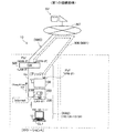
図1は、本発明の一実施例としての可搬型ネットワーク接続装置を適用したネットワークシステムの概略構成を示す説明図である。ネットワークシステム10は、ゲートウェイ装置500と、可搬型ネットワーク接続装置100と、クレードル200と、クライアントCL1と、トンネル経路900とを備えている。ネットワークシステム10は、クライアントCL1から送信されるパケット(レイヤ3パケット)をインターネットINTを介して転送すると共に、クライアント宛のパケットをクライアントCL1に届けるためのシステムである。したがって、クライアントCL1は、例えば、インターネットINTに接続されているサーバSVに対してデータのダウンロード要求を送信したり、サーバSVからデータをダウンロードしたりすることができる。
A. Example:
A1. System configuration:
FIG. 1 is an explanatory diagram showing a schematic configuration of a network system to which a portable network connection device as an embodiment of the present invention is applied. The
ゲートウェイ装置500は、ルータとして機能する据え置き型の装置であり、図示しないアクセス回線(電気通信事業者が提供する回線)を含むネットワークNW3を介してインターネットINTと接続されている。ゲートウェイ装置500は、ネットワークケーブルCaを介してクレードル200と接続されている。ゲートウェイ装置500は、LAN(有線LAN及び無線LAN)に接続するためのインタフェース(LAN−IF)と、アクセス回線(ネットワークNW3)に接続するためのインタフェース(WAN−IF:Wide Area Network-InterFace)と、トンネル経路900に接続するためのインタフェース(VPN−IF:Virtual Private Network-InterFace)とを備えている。WAN−IFには、グローバルIPアドレス「IPg1」が割り当てられている。ゲートウェイ装置500としては、例えば、ホームゲートウェイとしてISP(Internet Services Provider)事業者により提供される装置を採用し得る。なお、ゲートウェイ装置500の詳細構成は後述する。
The
クレードル200は、可搬型ネットワーク接続装置100と接続可能に構成されており、可搬型ネットワーク接続装置100を載置するためのスタンドとしての機能,可搬型ネットワーク接続装置100に電力を中継する装置としての機能,および可搬型ネットワーク接続装置100を有線LANに接続させるための機能を有する。クレードル200は、ポート220と切替スイッチ230とを備えている。ポート220は、クレードル200と有線LAN(Local Area Network)とを接続するためのポートであり、図1に示すようにネットワークケーブルCaが接続されている。切替スイッチ230はいわゆるスライドスイッチであり、ポート220の機能を切り替えるためのスイッチである。
The
可搬型ネットワーク接続装置100は、レイヤ3またはレイヤ2においてパケット(フレーム)を中継する小型軽量の可搬型装置である。可搬型ネットワーク接続装置100は、クレードル200に対して着脱自在に接続し得る。なお、図1では、可搬型ネットワーク接続装置100は、クレードル200と接続されている。
The portable
また、可搬型ネットワーク接続装置100は、パケットの転送処理の動作モードとして、2つの動作モードを有している。具体的には、可搬型ネットワーク接続装置100は、レイヤ2においてパケットを中継する動作モード(すなわち、ブリッジとして動作する動作モード)である第1動作モードと、レイヤ3においてパケットを中継する動作モード(すなわち、ルータとして動作する動作モード)である第2動作モードを有している。図1の例では、可搬型ネットワーク接続装置100は第1動作モード(ブリッジ)で動作している。ここで、「ルータ」とは、レイヤ3でパケットを中継する機能であって、互いに異なるネットワーク(ブロードキャストドメイン)間でパケットを中継する機能を意味する。また、「ブリッジ」とは、レイヤ2でパケット(フレーム)を中継する機能であって、単一のネットワーク(ブロードキャストドメイン)内におけるパケット(フレーム)を中継する機能を意味する。
The portable
また、可搬型ネットワーク接続装置100は、LAN(有線LAN及び無線LAN)に接続するためのインタフェース(LAN−IF)と、トンネル経路900(ネットワークNW1)に接続するためのインタフェース(VPN−IF)とを備えている。可搬型ネットワーク接続装置100が有するVPN−IFには、グローバルIPアドレス「IPg2」が割り当てられている。なお、LAN−IF,VPN−IFを含む可搬型ネットワーク接続装置100の詳細構成は、後述する。
The portable
本実施例において、クライアントCL1は、パーソナルコンピュータである。クライアントCL1は、図示しない無線LANインタフェースを有しており、この無線LANインタフェースを介して可搬型ネットワーク接続装置100と接続されている。図1では、クライアントCL1は、無線LANのクライアントとして動作している。可搬型ネットワーク接続装置100はルータとして動作すると共に、無線LANのアクセスポイントとして動作している。
In this embodiment, the client CL1 is a personal computer. The client CL1 has a wireless LAN interface (not shown), and is connected to the portable
トンネル経路900は、ゲートウェイ装置500と可搬型ネットワーク接続装置100との間に形成されたインターネットINTを経由するパケット転送経路である。トンネル経路900は、図示しない移動体通信網、及びゲートウェイ装置500がインターネットINTに接続するためのアクセス回線からなるネットワークNW1により形成される。トンネル経路900では、転送されるべきパケット(レイヤ3パケット)は、パケットの送信元において付与された宛先IPアドレス及び送信元IPアドレスとは異なる宛先IPアドレス及び送信元IPアドレスが割り当てられたヘッダによってカプセル化されて転送される。本実施例では、トンネル経路900として、ISPや電気通信事業者が提供する周知のネットワーク(VPN)を利用できる。トンネル経路900では、ゲートウェイ装置500と可搬型ネットワーク接続装置100との間でやり取りされるIPパケットが暗号化され、第三者による盗聴が抑制される。本実施例では、かかる暗号化プロトコルとして、IETF(Internet Engineering Task Force)において規定されるIPSec(Security Architecture for Internet Protocol)が用いられる。
The
ネットワークシステム10では、各構成要素間の接続態様として、複数の接続態様を許容している。図1では、ネットワークシステム10の第1の接続態様を示している。第1の接続態様では、各構成要素は、いずれも同じロケーションA(例えば、家庭やオフィス)に配置されている。第1の接続態様では、ゲートウェイ装置500よりも下位側(インターネットINTから離れている側)には、1つのネットワークNW2が形成されている。ネットワークNW2には、プライベートネットワークアドレスである「192.168.11.0/24」が割り当てられている。ネットワークNW2に所属するクライアントCL1には、IPアドレス「192.168.11.11」が割り当てられている。ゲートウェイ装置500は、グローバルIPアドレス(IPg1)とプライベートIPアドレス(192.168.11.10等)との相互変換を行うアドレス変換機能を備えている。アドレス変換機能としては、例えば、NAT(Network Address Translation)機能やNAPT(Network Address Port Translation)機能を採用することができる。
In the
図2は、ネットワークシステムの第2の接続態様を示す説明図である。第2の接続態様では、各構成要素は同一のロケーションに配置されていない。具体的には、図2左側に示すロケーションAには、ゲートウェイ装置500とクレードル200とネットワークケーブルCaとが配置されている。図2右側に示すロケーションBには、可搬型ネットワーク接続装置100と、クライアントCL1と、クライアントCL2とが配置されている。なお、第1実施例において、ロケーションAとロケーションBとは、互いに大きく離れている(例えば、無線LANアクセスポイントと無線LANクライアント間の通信ができない程度に離れている)。
FIG. 2 is an explanatory diagram showing a second connection mode of the network system. In the second connection mode, the components are not arranged at the same location. Specifically, a
クライアントCL2は、クライアントCL1と同様にパーソナルコンピュータであり、図示しない無線LANインタフェースを有している。クライアントCL2は、図示しない無線LANインタフェースを介して可搬型ネットワーク接続装置100と接続されている。ロケーションBにはプライベートネットワークアドレスが割り当てられたネットワークNW4(192.168.11.0/24)が形成されている。クライアントCL2にはプライベートIPアドレスである「192.168.11.12」が割り当てられている。
The client CL2 is a personal computer like the client CL1, and has a wireless LAN interface (not shown). The client CL2 is connected to the portable
可搬型ネットワーク接続装置100は、図示しない移動体通信インタフェースを備えており、この移動体通信インタフェースを介して図示しない移動体通信網の基地局と無線通信を行う。図2では、可搬型ネットワーク接続装置100は、ルータとして動作しており、クライアントCL1又はクライアントCL2からインターネットINTに向かうパケットや、インターネットINTからクライアントCL1又はクライアントCL2に向かうパケットを転送する。
The portable
可搬型ネットワーク接続装置100は、2台のクライアントCL1,CL2がインターネットINTを介した通信を行う際に、各クライアントCL1,CL2のプライベートIPアドレスを、グローバルIPアドレス(IPg2)でカプセル化する。
When the two clients CL1 and CL2 perform communication via the Internet INT, the portable
第2の接続態様は、例えば、ロケーションAにおいて図1に示す第1の接続態様が実現されている状態から、ユーザが、可搬型ネットワーク接続装置100をクレードル200から切り離し、可搬型ネットワーク接続装置100とクライアントCL1とをロケーションBに持ち出し、新たなクライアントであるクライアントCL2が、無線LANアクセスポイントとして動作する可搬型ネットワーク接続装置100と無線により接続された場合に実現し得る。ロケーションAからの可搬型ネットワーク接続装置100及びクライアントCL1の持ち出しは、例えば、ユーザが、クライアントCL1とサーバSVとの間でデータのやり取りを行っている状態を維持したまま、ロケーションBに移動しようとする場合に起こり得る。このようなクライアントCL1とサーバSVとのデータのやり取りとしては、例えば、サーバSVから出力される映像のストリーム送信や、サーバSVからのファイル転送などを採用できる。
In the second connection mode, for example, the user disconnects the portable
図3は、ネットワークシステムの第3の接続態様を示す説明図である。クレードル200及びネットワークケーブルCaがロケーションAから持ち出されてロケーションCに移動されている点と、クライアントCL3が有線によりクレードル200に接続されている点と、を除き、図2に示す第2の接続態様と同じである。なお、ロケーションAとロケーションCとは、互いに大きく離れている(例えば、無線LANアクセスポイントと無線LANクライアント間の通信ができない程度に離れている)。
FIG. 3 is an explanatory diagram showing a third connection mode of the network system. 2 except that the
クライアントCL3は、クライアントCL1と同様にパーソナルコンピュータであり、図示しない有線LANインタフェースを有している。クライアントCL3は、図示しない有線LANインタフェース及びネットワークケーブルCaを介してクレードル200と接続されている。ロケーションCにはプライベートネットワークアドレスが割り当てられたネットワークNW5(192.168.11.0/24)が形成されている。クライアントCL3にはプライベートIPアドレスである「192.168.11.13」が割り当てられている。
The client CL3 is a personal computer like the client CL1, and has a wired LAN interface (not shown). The client CL3 is connected to the
このような第3の接続態様は、例えば、ロケーションAにおいて図1に示す第1の接続態様が実現されている状態から、ユーザが、ロケーションCにおいて新たなネットワークを構築するために、可搬型ネットワーク接続装置100とクライアントCL1とをロケーションCに持ち出し、新たなクライアントであるクライアントCL3が、可搬型ネットワーク接続装置100と有線接続された場合に実現し得る。
Such a third connection mode is a portable network in which, for example, the user can construct a new network at the location C from the state where the first connection mode shown in FIG. This can be realized when the
図4は、可搬型ネットワーク接続装置及びクレードルの詳細構成を示す説明図である。クレードル200は、上述したポート220及び切替スイッチ230に加えて、接続インタフェース(I/F)280と、LAN制御回路210とを備えている。ポート220及びLAN制御回路210は互いに内部バスで接続されている。同様に、LAN制御回路210及び接続インタフェース280は互いに内部バスで接続されている。
FIG. 4 is an explanatory diagram showing a detailed configuration of the portable network connection device and the cradle. The
ポート220としては、例えば、IEEE802.3/3u/3abに準拠したポートを採用することができる。LAN制御回路210は、所定のネットワークプロトコル(例えばイーサネット(登録商標))に従いポート220を介したデータ伝送を制御する。LAN制御回路210は、LAN−IF192を備えている。LAN−IF192は、LAN制御回路210に形成された論理的なインタフェースであり、有線LANを介したデータのやり取りを行うためのインタフェースである。
As the
切替スイッチ230は、「Internet」の状態と「Lan」の状態とのいずれかに手動で切り換えられる。図4では、切替スイッチ230は、「Internet」の状態に設定されている。ポート220は、切替スイッチ230の状態が「Lan」である場合にクライアントと接続するために用いられるポートとして機能し、切替スイッチ230の状態が「Internet」の場合にゲートウェイ装置500と接続するためのポートとして機能する。
The
接続インタフェース280は、USB(Universal Serial Bus)デバイスコントローラとしての機能を有しており、クレードル200が可搬型ネットワーク接続装置100と接続されているとき、USB規格に則って可搬型ネットワーク接続装置100との間での情報のやり取りを行う。
The
可搬型ネットワーク接続装置100は、USBデバイスインタフェース173と、無線LAN制御回路174と、無線WAN制御回路175と、移動体通信制御回路176と、クレードル200との接続のためのクレードル接続インタフェース(I/F)180と、CPU(Central Processing Unit)120と、ROM(Read Only Memory)171と、RAM(Random Access Memory)172とを含んでいる。USBデバイスインタフェース173は、USB(Universal Serial Bus)デバイス(例えば、記憶装置など)を接続するためのインタフェースである。
The portable
無線LAN制御回路(「無線LANインタフェース」とも呼ばれる)174は、変調器やアンプ、アンテナを含み、例えばIEEE802.11b/gに準拠した無線LANのアクセスポイントとして、無線LANのクライアント(例えばパーソナルコンピュータやゲーム機)と無線通信を行う。無線LAN制御回路174は、LAN−IF191を備えている。LAN−IF191は、無線LAN制御回路174に形成された論理的なインタフェースであり、無線LANを介したデータのやり取りを行うためのインタフェースである。
The wireless LAN control circuit (also referred to as “wireless LAN interface”) 174 includes a modulator, an amplifier, and an antenna. For example, as a wireless LAN access point compliant with IEEE802.11b / g, a wireless LAN client (for example, a personal computer or Wireless communication with game consoles. The wireless
無線WAN制御回路(「無線WANインタフェース」とも呼ばれる)175は、変調器やアンプ、アンテナを含み、例えばIEEE802.11a/b/gに準拠した無線LANのクライアントとして、無線LANのアクセスポイント(例えば公衆無線LAN)と無線通信を行う。無線WAN制御回路175は、WAN−IF194を備えている。WAN−IF194は、無線WAN制御回路175に形成された論理的なインタフェースであり、例えば公衆無線LANを介したデータのやり取りを行うためのインタフェースである。
The wireless WAN control circuit (also referred to as “wireless WAN interface”) 175 includes a modulator, an amplifier, and an antenna. For example, as a wireless LAN client compliant with IEEE802.11a / b / g, an access point (for example, a public LAN) Wireless communication is performed with a wireless LAN. The wireless WAN control circuit 175 includes a WAN-
移動体通信制御回路(「移動体通信インタフェース」とも呼ばれる)176は、変調器やアンプ、アンテナを含み、例えば3G/HSPAに準拠した移動体通信の端末として、移動体通信網の基地局と無線通信を行う。移動体通信制御回路176は、VPN−IF193を備えている。VPN−IF193は、移動体通信制御回路176に形成された論理的なインタフェースであり、VPN(トンネル経路900)を介してデータをやり取りするためのインタフェースである。このように、第1実施例の可搬型ネットワーク接続装置100は、それぞれが互いに異なる無線通信ネットワークにおける無線通信を行う複数の無線通信インタフェースを含んでいる。
The mobile communication control circuit (also referred to as “mobile communication interface”) 176 includes a modulator, an amplifier, and an antenna. For example, as a mobile communication terminal compliant with 3G / HSPA, the mobile
クレードル接続インタフェース180は、USBホストコントローラとしての機能を有しており、可搬型ネットワーク接続装置100がクレードル200と接続されているとき、USB規格に則ってクレードル200との間での情報のやり取りを行う。また、クレードル接続インタフェース180は、可搬型ネットワーク接続装置100がクレードル200と接続されているとき、接続インタフェース280を介してクレードルから供給される電力を、可搬型ネットワーク接続装置100側の図示しないバッテリーに受け渡す。
The
CPU120は、ROM171に格納されているファームウェアやコンピュータプログラムをRAM172に展開して実行することにより、可搬型ネットワーク接続装置100の各部を制御すると共に、転送処理部121,転送制御部122,切替監視部123,クレードル接続監視部124,ゲートウェイ装置接続監視部125,VPN制御部126として機能する。
The
転送処理部121は、ルータ機能部121rと、ブリッジ機能部121bとを有しており、各無線通信インタフェース(無線LAN制御回路174,無線WAN制御回路175,移動体通信制御回路176)及びポート220を介したパケット(レイヤ3パケット及びレイヤ2フレーム)の転送を行う。転送処理部121はパケット転送の動作モードとして、ブリッジ機能部121bのみが処理を行う第1の動作モードと、ブリッジ機能部121b及びルータ機能部121rが処理を行う第2の動作モードとを有している。第1の動作モードでは、ブリッジ機能部121bのみがレイヤ2フレームの転送を行うため、可搬型ネットワーク接続装置100及びクレードル200は、全体としてブリッジとして動作する。これに対し、第2の動作モードでは、ブリッジ機能部121b及びルータ機能部121rのいずれもが処理を行うため、可搬型ネットワーク接続装置100及びクレードル200は、全体としてルータとして動作する。
The
転送制御部122は、転送処理部121を制御する。かかる制御の1つとして、転送制御部122は、後述する動作モード切り替え処理を実行することにより、転送処理部121の動作モードを設定する(切り替える)。
The
切替監視部123は、切替スイッチ230の切り替え状態を監視する。具体的には、例えば、切替スイッチ230とCPU120のGPIO(General Purpose Input/Output)ポートとを図示しない制御線により接続し、かかる制御線を介してCPU120に入力される割り込み信号により、切替スイッチ230の切り替え状態を監視することができる。なお、切替監視部123は、可搬型ネットワーク接続装置100の電源がオンとなった後、切替スイッチ230の切り替え状態の変化(操作の有無)を常時監視している。
The
クレードル接続監視部124は、可搬型ネットワーク接続装置100がクレードル200に接続されているか否かを監視する機能部である。この監視は、例えば、クレードル接続インタフェース180と接続インタフェース280との間における給電の有無により監視することができる。また、例えば、USB規格における装置間の接続検出シーケンス(例えば、D+,D−のいずれかが3.3Vとなる場合に接続と検出)に従って、可搬型ネットワーク接続装置100とクレードル200との接続の有無を監視することができる。なお、接続監視部124は、可搬型ネットワーク接続装置100の電源がオンとなった後、可搬型ネットワーク接続装置100とクレードル200との接続の有無を常時監視している。
The cradle
ゲートウェイ装置接続監視部125は、可搬型ネットワーク接続装置100とゲートウェイ装置500との接続の有無を監視すると共に、可搬型ネットワーク接続装置100の存在を通知する信号(図1に示すキープアライブ信号KA)を出力する。ここで、「ゲートウェイ装置500との接続の有無」とは、可搬型ネットワーク接続装置100が所属するネットワークにゲートウェイ装置500が所属しているか否かを意味する。なお、ゲートウェイ装置接続監視部125によるキープアライブ信号KAの出力は、予めゲートウェイ装置500のアドレスを登録しておき、かかるアドレスへのユニキャストにより実現することができる。また、これに代えて、可搬型ネットワーク接続装置100が所属するネットワーク内にブロードキャストすることにより実現することもできる。
The gateway device
VPN制御部126は、トンネル経路900を介したデータのやり取りを制御する。具体的には、認証や暗号鍵のやり取りなど、トンネル経路900を確立するための処理や、トンネル経路900を介したデータのやり取りに伴う暗号化及び復号化の処理や、データの圧縮及び伸張などの処理を実行する。なお、VPN制御部126は、可搬型ネットワーク接続装置100の起動後において、トンネル経路900の他端に当たる機能部(後述のゲートウェイ装置500のVPN制御部)との間で、トンネル経路900を確立するための処理(認証等)を定期的に行っている。したがって、トンネル経路900は、ゲートウェイ装置500及び可搬型ネットワーク接続装置100の起動後において、継続して確立されている。
The
ROM171は、書き込み可能な不揮発性メモリである。ROM171には、上記各機能部を実現するための図示しないプログラムに加えて、VPN設定データ格納部17aと、ルーティングテーブル格納部17bと、ARPテーブル格納部17cとを備えている。VPN設定データ格納部17aは、VPNを形成するために用いる各種データを格納する。具体的には、例えば、VPN(トンネル経路900)を介して接続する装置との間で認証を行うための暗号鍵や、トンネル用IPアドレス(図1,2に示す「IPg2」)や、やりとりするデータを圧縮するか否かを示すデータなどを格納する。
The
ルーティングテーブル格納部17bは、ルーティングテーブルRT3を格納する。ルーティングテーブルRT3は、可搬型ネットワーク接続装置100がルータとして機能する場合に、転送処理部121(ルータ機能部121r)によって参照される。
The routing table storage unit 17b stores the routing table RT3. The routing table RT3 is referred to by the transfer processing unit 121 (router function unit 121r) when the portable
図5は、図4に示すルーティングテーブルの設定内容を示す説明図である。ルーティングテーブルRT3は、宛先アドレスと、条件と、出力インタフェース(I/F)とを互いに対応付けている。宛先アドレスとは、転送しようとするパケットの宛先アドレスを示す。条件とは、各エントリを適用する前提となる条件を意味する。出力I/Fは、転送すべきパケットの出力先インタフェースを示す。 FIG. 5 is an explanatory diagram showing the setting contents of the routing table shown in FIG. The routing table RT3 associates a destination address, a condition, and an output interface (I / F) with each other. The destination address indicates the destination address of the packet to be transferred. The condition means a condition that is a premise for applying each entry. The output I / F indicates an output destination interface of a packet to be transferred.
図5に示すように、本実施例のルーティングテーブルRT3には、3つのエントリが登録されている。最上段のエントリには、宛先「192.168.11.0/24」,条件「ARP登録」,出力I/F「LAN−IF」が設定されている。このエントリは、宛先アドレスのネットワークアドレスが「192.168.11.0/24」であるパケットのうち、図示しないARPテーブルに登録されているアドレスのパケットについては、出力インタフェースがLAN−IFになることを意味する。中段のエントリには、宛先「192.168.11.0/24」,条件「無し」,出力I/F「VPN−IF」が設定されている。このエントリは、宛先アドレスのネットワークアドレスが「192.168.11.0/24」であるパケットについては、無条件で出力インタフェースがVPN−IFになることを意味する。最下段のエントリには、宛先「*」,条件「無し」,出力I/F「VPN−IF」が設定されている。このエントリは、宛先アドレスが任意のパケットについては、無条件で出力インタフェースがVPN−IFになることを意味する。これら3つのエントリの登録は、予めユーザが設定用端末(パーソナルコンピュータ等)を可搬型ネットワーク接続装置100に接続して手動で設定しておくことができる。ルーティングテーブルRT3が参照される際には、該当するエントリがヒットするまで、最上段のエントリ,中段のエントリ,最下段のエントリの順序で参照(検索)される。
As shown in FIG. 5, three entries are registered in the routing table RT3 of the present embodiment. In the uppermost entry, a destination “192.168.11.0/24”, a condition “ARP registration”, and an output I / F “LAN-IF” are set. In this entry, the output interface of the packet whose address is registered in the ARP table (not shown) among the packets whose destination address network address is “192.168.11.0/24” is LAN-IF. Means that. In the middle entry, the destination “192.168.11.0/24”, the condition “none”, and the output I / F “VPN-IF” are set. This entry means that the output interface is VPN-IF unconditionally for a packet whose destination address is “192.168.11.0/24”. In the lowermost entry, a destination “*”, a condition “none”, and an output I / F “VPN-IF” are set. This entry means that the output interface is VPN-IF unconditionally for a packet with an arbitrary destination address. The registration of these three entries can be set manually by a user connecting a setting terminal (such as a personal computer) to the portable
図4のARPテーブル格納部17cには、図示しないARPテーブルが格納されている。ARPテーブルとは、IPアドレスとMAC(Media Access Control)アドレスとを対応付けたテーブルであり、クライアントと通信を行うたびにエントリが追加(学習)される。可搬型ネットワーク接続装置100が所属するネットワークと同じネットワーク(ブロードキャストドメイン)内のクライアントについては、学習によりエントリが登録されるが、可搬型ネットワーク接続装置100が所属するネットワークとは異なるネットワーク内のクライアントについては、ARPテーブルにエントリは登録されない。
An ARP table (not shown) is stored in the ARP
図6は、ゲートウェイ装置の詳細構成を示す説明図である。ゲートウェイ装置500は、CPU320と、RAM330と、ROM340と、無線LAN制御回路350と、有線LAN制御部360とを備えている。
FIG. 6 is an explanatory diagram showing a detailed configuration of the gateway device. The
CPU320は、ROM340に格納されているコンピュータプログラムをRAM330に展開して実行することにより、転送処理部321,経路決定部322,接続監視部323,アドレス変換部324,VPN制御部325の各機能部として動作する。
The
転送処理部321は、有線LAN制御部360や無線LAN制御回路350を介して入力されるIPパケットを転送する。経路決定部322は、パケットの転送経路を決定する。接続監視部323は、ゲートウェイ装置500が所属するネットワークに可搬型ネットワーク接続装置100が所属しているか否かを監視する。具体的には、接続監視部323は、所定期間内に前述のキープアライブ信号KAを受信した場合に、ゲートウェイ装置500が所属するネットワークに可搬型ネットワーク接続装置100が所属していると判定し、所定期間内にキープアライブ信号KAを受信しない場合に、ゲートウェイ装置500が所属するネットワークに可搬型ネットワーク接続装置100が所属していないと判定する。アドレス変換部324は、グローバルIPアドレスとプライベートIPアドレスとを変換する。VPN制御部325は、図4に示す可搬型ネットワーク接続装置100のVPN制御部126と同じ機能を有する。
The
ROM340は、書き込み可能な不揮発性メモリである。上記各機能部を実現するための図示しないプログラムに加えて、ルーティングテーブル格納部341と、VPN設定データ格納部342と、ARPテーブル格納部343とを備えている。ルーティングテーブル格納部341には、第1ルーティングテーブルRT1と、第2ルーティングテーブルRT2とが格納されている。これら2つのルーティングテーブルRT1,RT2は、予めユーザが設定用端末(パーソナルコンピュータ等)をゲートウェイ装置500に接続して手動で設定しておくことができる。
The
図7は、図6に示す第1ルーティングテーブルの設定内容を示す説明図である。第1ルーティングテーブルRT1は、図5に示すルーティングテーブルRT3と同様に、宛先アドレスと、条件と、出力インタフェース(I/F)とを互いに対応付けている。 FIG. 7 is an explanatory diagram showing the setting contents of the first routing table shown in FIG. As in the routing table RT3 shown in FIG. 5, the first routing table RT1 associates destination addresses, conditions, and output interfaces (I / F) with each other.
図7に示すように、本実施例の第1ルーティングテーブルRT1には、2つのエントリが登録されている。上段のエントリには、宛先「192.168.11.0/24」,条件「無し」,出力I/F「LAN−IF」が設定されている。このエントリは、宛先アドレスのネットワークアドレスが「192.168.11.0/24」であるパケットについては、無条件で出力インタフェースがLAN−IFになることを意味する。下段のエントリには、宛先「*」,条件「無し」,出力I/F「WAN−IF」が設定されている。このエントリは、宛先アドレスが任意のパケットについては、無条件で出力インタフェースがWAN−IFになることを意味する。図5に示すルーティングテーブルRT3と同様に、これら2つのエントリは、上段のエントリ,下段のエントリの順序で参照される。 As shown in FIG. 7, two entries are registered in the first routing table RT1 of the present embodiment. In the upper entry, the destination “192.168.11.0/24”, the condition “none”, and the output I / F “LAN-IF” are set. This entry means that for a packet whose destination address is “192.168.11.0/24”, the output interface is unconditionally the LAN-IF. In the lower entry, a destination “*”, a condition “none”, and an output I / F “WAN-IF” are set. This entry means that the output interface is unconditionally the WAN-IF for a packet whose destination address is arbitrary. Similar to the routing table RT3 shown in FIG. 5, these two entries are referred to in the order of the upper entry and the lower entry.
図8は、図6に示す第2ルーティングテーブルの設定内容を示す説明図である。第2ルーティングテーブルRT2は、ルーティングテーブルRT3,第1ルーティングテーブルRT1と同様に、宛先アドレスと、条件と、出力インタフェース(I/F)とを互いに対応付けている。 FIG. 8 is an explanatory diagram showing the setting contents of the second routing table shown in FIG. Similar to the routing table RT3 and the first routing table RT1, the second routing table RT2 associates destination addresses, conditions, and output interfaces (I / F) with each other.
図8に示すように、本実施例の第2ルーティングテーブルRT2には、3つのエントリが登録されている。最上段のエントリには、宛先「192.168.11.0/24」,条件「ARP登録」,出力I/F「LAN−IF」が設定されている。このエントリは、図5の最上段のエントリと同じである。但し、「LAN−IF」の示す出力先は、図5のルーティングテーブルRT3とは異なる。中段のエントリには、「192.168.11.0/24」,条件「無し」,出力I/F「VPN−IF」が設定されている。このエントリは、図5の中段のエントリと同じである。但し、「VPN−IF」の示す出力先は、図5のルーティングテーブルRT3とは異なる。最下段のエントリには、宛先「*」,条件「無し」,出力I/F「WAN−IF」が設定されている。このエントリは、宛先アドレスが任意のパケットについては、無条件で出力インタフェースがWAN−IFになることを意味する。ルーティングテーブルRT3及び第1ルーティングテーブルRT1と同様に、これら3つのエントリは、最上段のエントリ,中段のエントリ,最下段のエントリの順序で参照される。
As shown in FIG. 8, three entries are registered in the second routing table RT2 of this embodiment. In the uppermost entry, a destination “192.168.11.0/24”, a condition “ARP registration”, and an output I / F “LAN-IF” are set. This entry is the same as the uppermost entry in FIG. However, the output destination indicated by “LAN-IF” is different from the routing table RT3 of FIG. In the middle entry, “192.168.11.0/24”, condition “none”, and output I / F “VPN-IF” are set. This entry is the same as the stage of the entry in the Fig. However, the output destination indicated by “VPN-IF” is different from the routing table RT3 of FIG. In the lowermost entry, a destination “*”, a condition “none”, and an output I / F “WAN-IF” are set. This entry means that the output interface is unconditionally the WAN-IF for a packet whose destination address is arbitrary. Similar to the routing table RT3 and the first routing table RT1, these three entries are referred to in the order of the uppermost entry, the middle entry, and the lowermost entry.
図6に示すVPN設定データ格納部342は、図4に示す可搬型ネットワーク接続装置100のVPN設定データ格納部17aと同じ機能を有する。ARPテーブル格納部343は、図4に示す可搬型ネットワーク接続装置100のARPテーブル格納部17cと同じ機能を有する。
The VPN setting
無線LAN制御回路350は、図4に示す可搬型ネットワーク接続装置100の無線LAN制御回路174と同じ機能を有する。無線LAN制御回路350は、LAN−IF391を備えている。LAN−IF391は、図4に示す可搬型ネットワーク接続装置100のLAN−IF191と同じ機能を有する。
The wireless
有線LAN制御部360は、図4に示すLAN制御回路210及びポート220と同じ機能を有する。有線LAN制御部360は、LAN−IF392と、VPN−IF393と、WAN−IF394とを備えている。LAN−IF392は、LAN−IF391と同様の機能を有する。VPN−IF393は、図4に示す可搬型ネットワーク接続装置100のVPN−IF193と同様の機能を有する。WAN−IF394は、WAN(インターネットINT)を介してデータをやり取りするためのインタフェースである。WAN−IF394及びVPN−IF393には、いずれもグローバルIPアドレス「IPg1」が割り当てられている。
The wired
ネットワークシステム10では、可搬型ネットワーク接続装置100は、後述の動作モード切り替え処理を実行することにより、ゲートウェイ装置500と同じネットワークに所属する場合にブリッジとして機能し、ゲートウェイ装置500とは異なるネットワークに所属する場合にルータとして機能する。また、ネットワークシステム10では、後述のパケット転送経路決定処理を実行することにより、クライアントCL1がサーバSVと通信したままの状態でロケーションAからロケーションBに移動する場合におけるセッションの切断を抑制することができる。
In the
ネットワークNW1は、請求項における第1のネットワークに相当する。また、ネットワークNW2は請求項における第2のネットワークに、ネットワークNW3は請求項における第3のネットワークに、VPN−IF193は請求項における第1のネットワークインタフェース部に、転送処理部121は請求項における第1のパケット転送処理部に、VPN制御部126は請求項における第1のカプセル化実行部に、WAN−IF394は請求項における第3のネットワークインタフェース部及び第3のネットワーク用インタフェース部に、VPN−IF393は請求項における第4のネットワークインタフェース部及び第1のネットワーク用インタフェース部に、LAN−IF391,392は請求項における第5のネットワークインタフェース部及び第2のネットワーク用インタフェース部に、接続監視部323は請求項における検出部に、転送処理部321は請求項における第2のパケット転送処理部及びパケット転送処理部に、VPN制御部325は請求項における第2のカプセル化実行部及びカプセル化実行部に、第1ルーティングテーブルRT1は請求項における第1のルーティングテーブルに、第2ルーティングテーブルRT2は請求項における第2のルーティングテーブルに、ゲートウェイ装置接続監視部125は請求項における通知パケット送信部に、それぞれ相当する。
The network NW1 corresponds to the first network in the claims. The network NW2 is the second network in the claims, the network NW3 is the third network in the claims, the VPN-
A2.動作モード切り替え処理:
図9は、可搬型ネットワーク接続装置において実行される動作モード切り替え処理の手順を示すフローチャートである。可搬型ネットワーク接続装置100では、可搬型ネットワーク接続装置100とクレードル200との接続状態に変化が生じた場合、又は、切替スイッチ230の切り替え状態に変化が生じた場合に、動作モード切り替え処理が実行される。なお、可搬型ネットワーク接続装置100(転送処理部121)の動作モードは、電源オンの時点では初期設定値である「第1動作モード(ブリッジ)」に設定される。
A2. Operation mode switching process:
FIG. 9 is a flowchart showing the procedure of the operation mode switching process executed in the portable network connection device. The portable
転送制御部122は、可搬型ネットワーク接続装置100がクレードル200に接続されているか否かを、接続監視部124を制御して判定する(ステップS105)。可搬型ネットワーク接続装置100がクレードル200に接続されている場合(ステップS105:YES)、転送制御部122は、ROM171に格納されている図示しないイーサネットドライバプログラムを、クレードル200が有するLAN制御回路210にロードする(ステップS110)。
The
転送制御部122は、切替監視部123を制御して、切替スイッチ230の状態が、「Internet」の状態であるか否かを判定する(ステップS115)。転送制御部122は、切替スイッチ230の状態が「Internet」の状態である場合には(ステップS115:YES)、転送処理部121の動作モードを第1動作モードに設定する(切り替える)(ステップS120)。一方、スイッチ230の状態が「Lan」の状態である場合には(ステップS115:NO)、転送制御部122は、転送処理部121の動作モードを第2動作モードに設定する(切り替える)(ステップS125)。
The
可搬型ネットワーク接続装置100がクレードル200に接続され(ステップS105:YES)、切替スイッチ230の状態が「Internet」の状態である場合には、可搬型ネットワーク接続装置100にはクレードル200を介してゲートウェイ装置500が接続されている(すなわち第1の接続態様である)と推定される。この場合、ゲートウェイ装置500がルータとして機能するので、可搬型ネットワーク接続装置100をブリッジとして機能する第1の動作モードで動作させるようにしている。このようにすることで、同一ネットワーク内にルータとしての機能を有する装置(ゲートウェイ)が複数台存在することを抑制し、クライアントCL1によるインターネットを介した通信が正常に行えなくなることを抑制するためである。
When the portable
これに対して、可搬型ネットワーク接続装置100がクレードル200に接続され(ステップS105:YES)、切替スイッチ230の状態が「Lan」の状態である場合には、クレードル200にはクライアントが接続されており、可搬型ネットワーク接続装置100はゲートウェイ装置500と接続されていない(すなわち第3の接続態様である)と推定される。この場合、可搬型ネットワーク接続装置100の所属するネットワークにはルータが存在しないので、可搬型ネットワーク接続装置100(転送処理部121)をルータとして機能する第2の動作モードで動作させるようにしている。このようにすることで、可搬型ネットワーク接続装置100が所属するネットワークにルータとして機能する装置(ゲートウェイ)が存在せず、クライアントCL1によるインターネットを介した通信が正常に行えなくなることを抑制するためである。
On the other hand, when the portable
前述のステップS105において、可搬型ネットワーク接続装置100がクレードル200に接続されていないと判定された場合(ステップS105:NO)、転送制御部122は、転送処理部121の動作モードを第2動作モードに設定する(ステップS125)。
When it is determined in step S105 described above that the portable
可搬型ネットワーク接続装置100がクレードル200に接続されていない場合には、可搬型ネットワーク接続装置100はゲートウェイ装置500と接続されておらず、クライアントと可搬型ネットワーク接続装置100とが無線LANで接続される(すなわち第2の接続態様である)と推定される。この場合、クライアントが所属するネットワークにはルータとして機能する装置が存在しないので、本実施例では、可搬型ネットワーク接続装置100(転送処理部121)をルータとして機能する第2の動作モードで動作させるようにしている。
When the portable
A3.パケット転送経路決定処理:
図10は、ゲートウェイ装置において実行されるパケット転送経路決定処理の手順を示すフローチャートである。ゲートウェイ装置500では、転送すべきパケットが到着すると、パケット転送経路決定処理が実行される。
A3. Packet forwarding route determination processing:
FIG. 10 is a flowchart illustrating a procedure of packet transfer route determination processing executed in the gateway device. In the
経路決定部322は、接続監視部323を制御して、ゲートウェイ装置500が所属するネットワーク(ネットワークNW2)に可搬型ネットワーク接続装置100が存在するか否かを判定する(ステップS205)。ゲートウェイ装置500が所属するネットワークに可搬型ネットワーク接続装置100が存在すると判定された場合(ステップS205:YES)、経路決定部322は、第1ルーティングテーブルRT1を参照して、パケットの宛先アドレスに基づき経路(出力インタフェース)を決定する(ステップS210)。
The
前述のステップS205において、ゲートウェイ装置500が所属するネットワークに可搬型ネットワーク接続装置100が存在しないと判定された場合(ステップS205:NO)、経路決定部322は、第2ルーティングテーブルRT2を参照して、パケットの宛先アドレスに基づき経路(出力インタフェース)を決定する(ステップS215)。このようにして、パケット転送経路決定処理により、パケットの出力インタフェースが決定されると、ゲートウェイ装置500の転送処理部321は、パケットを決定された出力インタフェースに転送する。
When it is determined in step S205 described above that the portable
図11は、第1の接続態様におけるクライアントとサーバとのデータのやり取りを模式的に示す説明図である。図12は、第2の接続態様におけるクライアントとサーバとのデータのやり取りを模式的に示す説明図である。 FIG. 11 is an explanatory diagram schematically showing data exchange between the client and the server in the first connection mode. FIG. 12 is an explanatory diagram schematically showing data exchange between the client and the server in the second connection mode.
図11に示すように、第1の接続態様において、クライアントCL1からサーバSVに向かうパケットは、可搬型ネットワーク接続装置100を介してゲートウェイ装置500において受信され、ゲートウェイ装置500において経路が決定される。なお、可搬型ネットワーク接続装置100はブリッジとして動作しており、IPパケットは終端されない。
As shown in FIG. 11, in the first connection mode, a packet from the client CL1 to the server SV is received by the
第1の接続態様においては、図11に示すように、可搬型ネットワーク接続装置100から出力されるキープアライブ信号KAはゲートウェイ装置500において受信可能であるので、クライアントCL1からサーバSVに向かうパケットの経路は、第1ルーティングテーブルRT1を用いて決定される。具体的には、かかるパケットの宛先アドレスはサーバSVのIPアドレスであるので、図7に示す下段のエントリがヒットし、パケットはWAN−IF(図6に示すWAN−IF394)に出力される。なお、このとき、ゲートウェイ装置500において、送信元IPアドレスが、「192.168.11.11」から「IPg1」に変更される。
In the first connection mode, as shown in FIG. 11, the keep-alive signal KA output from the portable
また、第1の接続態様において、サーバSVからクライアントCL1に向かうパケットは、ゲートウェイ装置500において受信され、宛先アドレスが「IPg1」から「192.168.11.11」に変更されると共に、経路が決定される。この場合も経路決定には、第1ルーティングテーブルRT1が用いられる。ここで、第1の接続態様においては、クライアントCL1は、ゲートウェイ装置500と同じネットワークNW2に所属しているので、ゲートウェイ装置500の図示しないARPテーブルには、クライアントCL1に関するエントリが登録されている。加えて、かかるパケットの宛先アドレスは「192.168.11.11」であるので、図7に示す上段のエントリがヒットし、パケットはLAN−IF(図6に示すLAN−IF391,392)に出力される。したがって、パケットは、ブリッジとして動作する可搬型ネットワーク接続装置100を介してクライアントCL1に届くこととなる。
In the first connection mode, a packet from the server SV to the client CL1 is received by the
このようにして、クライアントCL1とサーバSVとがデータのやり取りを行っている状態のまま、可搬型ネットワーク接続装置100及びクライアントCL1をロケーションBに持ち出すと、図12に示す第2の接続態様となる。
In this way, when the portable
可搬型ネットワーク接続装置100がクレードル200から取り外されると、図9に示す動作モード切り替え処理が実行され、ステップS105において可搬型ネットワーク接続装置100がクレードル200に接続されていないと判定され、可搬型ネットワーク接続装置100はルータとして動作する(ステップS125)。
When the portable
図12に示す第2の接続態様において、クライアントCL1からサーバSVに向かうパケットは、ルータとして動作する可搬型ネットワーク接続装置100において受信され、経路が決定される。かかるパケットの宛先アドレスはサーバSVのIPアドレスであるので、図5に示すルーティングテーブルRT3において、最下段のエントリがヒットし、パケットはVPN−IF(図4に示すVPN−IF193)に出力される。したがって、このパケットはトンネル経路900を通って、ゲートウェイ装置500のVPN−IF393に届く。
In the second connection mode shown in FIG. 12, a packet from the client CL1 to the server SV is received by the portable
ゲートウェイ装置500では、VPN−IF393からパケットを受信すると、パケットの経路が決定される。ここで、第2の接続態様では、図12に示すように、可搬型ネットワーク接続装置100から出力されるキープアライブ信号KAはゲートウェイ装置500には届かない。したがって、トンネル経路900(VPN−IF393)から受信したパケットの経路は、第2ルーティングテーブルRT2を用いて決定される。具体的には、かかるパケットの宛先アドレスはサーバSVのIPアドレスであるので、図8に示す最下段のエントリがヒットし、パケットはWAN−IF(図6に示すWAN−IF394)に出力される。なお、このとき、第1の接続態様と同様に、ゲートウェイ装置500において、送信元IPアドレスが、「192.168.11.11」から「IPg1」に変更される。
When the
また、第2の接続態様において、サーバSVからクライアントCL1に向かうパケットは、ゲートウェイ装置500において受信され、宛先アドレスが「IPg1」から「192.168.11.11」に変更されると共に、経路が決定される。この場合も経路決定には、第2ルーティングテーブルRT2が用いられる。ここで、第2の接続態様においては、クライアントCL1は、ゲートウェイ装置500が所属するネットワーク(ネットワークNW2)とは異なるネットワーク(ネットワークNW4)に所属しているので、ゲートウェイ装置500の図示しないARPテーブルには、クライアントCL1に関するエントリが登録されていない。加えて、かかるパケットの宛先アドレスは「192.168.11.11」であるので、図8の中段のエントリがヒットし、パケットはVPN−IF(図6に示すVPN−IF393)に出力される。したがって、このパケットはトンネル経路900を通って、可搬型ネットワーク接続装置100のVPN−IF193に届く。
In the second connection mode, a packet from the server SV to the client CL1 is received by the
可搬型ネットワーク接続装置100では、VPN−IF193からパケットを受信すると、パケットの経路が決定される。ここで、第2の接続態様では、クライアントCL1は、可搬型ネットワーク接続装置100が所属するネットワーク(ネットワークNW4)と同じネットワークに所属しているので、可搬型ネットワーク接続装置100の図示しないARPテーブルには、クライアントCL1に関するエントリが登録されている。加えて、クライアントCL1に向かうパケットの宛先アドレスは「192.168.11.11」であるので、図5の最上段のエントリがヒットし、パケットはLAN−IF(図4に示すLAN−IF191,192)に出力される。したがって、パケットは、ブリッジ(アクセスポイント)として動作する可搬型ネットワーク接続装置100を介してクライアントCL1に届く。
When the portable
このように、図11に示す第1の接続態様及び図12に示す第2の接続態様において、サーバSVから出力されるクライアントCL1宛のパケットを受信する装置(ゲートウェイ)は、いずれもゲートウェイ装置500ある。換言すると、図11に示す第1の接続態様及び図12に示す第2の接続態様のいずれにおいても、サーバSVからクライアントCL1に向かうパケットの宛先IPアドレス(グローバルIPアドレス)はゲートウェイ装置500のWAN−IF394に割り当てられた「IPg1」である。したがって、クライアントCL1とサーバSVとがデータのやり取りを行っている状態のまま、クライアントCL1及び可搬型ネットワーク接続装置100が持ち出されて第2の接続状態になった場合も、ネットワークシステム10におけるゲートウェイのIPアドレスは変更しないので、サーバSVとクライアントCL1との間のセッションは切断されない。
As described above, in the first connection mode illustrated in FIG. 11 and the second connection mode illustrated in FIG. 12, any device (gateway) that receives a packet addressed to the client CL1 output from the server SV is the
なお、図12に示す第2の接続態様の状態から、可搬型ネットワーク接続装置100及びクライアントCL1がロケーションAに戻り、図11に示す第1の接続態様に変化した場合には、ゲートウェイ装置500では、サーバSVからクライアントCL1に向かうパケットの転送経路を決定する際に、第1ルーティングテーブルRT1が用いられる。したがって、この場合もパケットはクライアントCL1に届くこととなる。
If the portable
以上説明したように、本実施例のネットワークシステム10では、ゲートウェイ装置500と可搬型ネットワーク接続装置100との間をトンネル経路900で接続し、また、ゲートウェイ装置500において、同じネットワーク(ネットワークNW2)内に可搬型ネットワーク接続装置100が存在しない場合にクライアントCL1宛のパケットを転送する際に用いるルーティングテーブルとして、パケットがトンネル経路900に転送されるようなエントリを有する第2ルーティングテーブルRT2を用いるようにしている。したがって、第1の接続態様から第2の接続態様に変化した場合であっても、サーバSVからクライアントCL1宛のパケット(宛先IPアドレスが「IPg1」であるパケット)を、クライアントCL1に届けることができる。
As described above, in the
加えて、ゲートウェイ装置500において、同じネットワーク内に可搬型ネットワーク接続装置100が存在する場合にクライアントCL1宛のパケットを転送する際に用いるルーティングテーブルとして、パケットがLAN−IF191,192を介して出力されるようなエントリを有する第1ルーティングテーブルRT1を用いるようにしている。したがって、第2の接続態様から第1の接続態様に変化した場合であっても、サーバSVからクライアントCL1宛のパケット(宛先IPアドレスが「IPg1」であるパケット)を、クライアントCL1に届けることができる。以上より、ネットワークシステム10によると、可搬型ネットワーク接続装置100をゲートウェイ装置500の所属するネットワークNW2から他のネットワークNW4に移動させる場合、及び他のネットワークNW4からゲートウェイ装置500の所属するネットワークNW2に移動させる場合に、クライアントCL1とサーバSVとの間のセッションの切断を抑制できる。したがって、ユーザは、第1の接続態様から第2の接続態様に変化した場合に、再びクライアントCL1とサーバSVとの間のセッションを確立する作業を行う必要がない。
In addition, in the
B.変形例:
この発明は、上記の実施例や実施形態に限られるものではなく、その要旨を逸脱しない範囲において種々の態様において実施することが可能であり、例えば次のような変形も可能である。
B. Variation:
The present invention is not limited to the above-described examples and embodiments, and can be implemented in various modes without departing from the gist thereof. For example, the following modifications are possible.
B1.変形例1:
上記実施例では、トンネル経路900は、暗号化プロトコルとしてIPSecを用いたトンネル経路であったが、本発明はこれに限定されるものではない。例えば、PPTP(Point to Point Tunneling Protocol)を用いたトンネル経路を採用することができる。また、例えば、IETFにおいて規定されるMobileIPを用いて形成されたトンネル経路を採用することもできる。MobileIPを用いて形成されたトンネル経路を採用する構成では、ゲートウェイ装置500は、ホームエージェント(HA)として機能する機能部を有し、可搬型ネットワーク接続装置100は、フォーリンエージェント(FA)として機能する機能部を有し、クライアントCL1は、モバイルノード(MN)として機能する機能部を有することが好ましい。このようにMobileIPを用いて形成されたトンネル経路を採用する場合、サーバSVからクライアントCL1宛のパケットについては、ホームエージェントであるゲートウェイ装置500が受け取り、トンネル経路を介して可搬型ネットワーク接続装置に転送される。しかしながら、クライアントCL1からサーバSV宛のパケットは、クライアントCL1から直接サーバSVに送信される。したがって、この場合、クライアントCL1は、移動体通信網等など、可搬型ネットワーク接続装置を介さずにインターネットINTに接続する経路を有する。このとき、クライアントCL1が送信元であり、サーバSVが宛先となるパケットは、ゲートウェイ装置500において受信されないので、ゲートウェイ装置500の経路決定部322は、クライアントCL1からサーバSV宛のパケットについて経路を決定しない。
B1. Modification 1:
In the above embodiment, the
すなわち、一般には、ゲートウェイ装置500が所属するネットワークNW2において可搬型ネットワーク接続装置100無しが検出されると、ネットワークNW3(サーバSV)からクライアントCL1宛のパケットを転送する際の経路として、ネットワークNW3からトンネル経路900(ネットワークNW1)に向かう経路を決定する経路決定部を有するネットワークシステムを、本発明のネットワークシステムとして採用することができる。
That is, generally, when the absence of the portable
B2.変形例2:
上記実施例では、ゲートウェイ装置500において、転送すべきパケットを受信するたびにパケット転送経路決定処理が実行され、経路決定に用いるルーティングテーブルの決定と、決定されたルーティングテーブルにおける出力先インタフェースの決定とが行われていたが、本発明は、これに限定されるものではない。例えば、経路決定に用いるルーティングテーブルの決定は、経路(出力先インタフェース)を決定するタイミングと異なるタイミングで実行することもできる。具体的には、経路決定に用いるルーティングテーブルの決定は、転送すべきパケットの受信の有無に関わらず定期的に実行し、経路(出力先インタフェース)の決定は、実施例と同様に、転送すべきパケットを受信するたびに実行する構成を採用することもできる。このような構成により、転送すべきパケットを受信するたびにルーティングテーブルを決定せずに済むため、各パケットの転送に要する期間を短くすることができる。
B2. Modification 2:
In the above embodiment, every time a packet to be transferred is received in the
B3.変形例3:
上記実施例では、ゲートウェイ装置500では、互いに異なる2つのルーティングテーブルRT1,RT2を用意することにより、ネットワークNW2に可搬型ネットワーク接続装置100が存在する場合と存在しない場合とで、パケットの転送経路を異ならせていたが、本発明はこれに限定されるものではない。例えば、ゲートウェイ装置500に用意するルーティングテーブルは1つとし、このルーティングテーブルを、ネットワークNW2に可搬型ネットワーク接続装置100が存在する状態から存在しない状態に変化した場合、または、存在しない状態から存在する状態に変化した場合に書き換えるようにすることもできる。具体的には、ネットワークNW2に可搬型ネットワーク接続装置100が存在する状態から存在しない状態に変化した場合には、ルーティングテーブルを、図7に示す設定内容から図8に示す設定内容に書き換え、存在しない状態から存在する状態に変化した場合には、図8に示す設定内容から図7に示す設定内容に書き換える構成を採用することもできる。
B3. Modification 3:
In the above-described embodiment, the
B4.変形例4:
上記実施例では、キープアライブ信号KAは、可搬型ネットワーク接続装置100及びゲートウェイ装置500のうち、可搬型ネットワーク接続装置100のみが出力していたが、これに代えて、いずれも出力する構成を採用することができる。このような構成とすることで、可搬型ネットワーク接続装置100は、自らが所属するネットワークと同じネットワークにおけるゲートウェイ装置500の存在の有無を、ゲートウェイ装置500が出力するキープアライブ信号の受信の有無により判定することができる。したがって、動作モード切り替え処理の手順をよりシンプルにすることができる。すなわち、ゲートウェイ装置500が出力するキープアライブ信号を受信した場合には、第1動作モードに設定し、キープアライブ信号を受信しない場合には、第2動作モードに設定することができる。また、かかる構成を採用することにより、可搬型ネットワーク接続装置100と同じネットワークにゲートウェイ装置500が存在するか否かをより正確に判定することができる。
B4. Modification 4:
In the above embodiment, the keep-alive signal KA is output only by the portable
なお、上記のように可搬型ネットワーク接続装置100及びゲートウェイ装置500のいずれもキープアライブ信号を出力する構成としては、例えば、VRRP(Virtual Router Redundancy Protocol)を用いる構成を採用することができる。具体的には、可搬型ネットワーク接続装置100及びゲートウェイ装置500のいずれもVRRPに対応させ、これら2つの装置により仮想ルータを形成させる。VRRPでは、仮想ルータを形成する装置同士は、互いにキープアライブ信号(VRRP広告)を定期的に送信し、それぞれ他の装置から受信したVRRP広告に基づきマスタルータ及びバックアップルータのいずれとして動作するかを決定する。したがって、定期的に送信するキープアライブ信号を利用して、可搬型ネットワーク接続装置100及びゲートウェイ装置500は、それぞれ自らのネットワークにおける他方の装置の存在の有無を定期的に判定することができる。また、このような構成を採用することにより、可搬型ネットワーク接続装置100の存在及びゲートウェイ装置500の存在を通知するパケットを送信するための機能部として、VRRP広告メッセージを示すパケットを送信する機能部とは別に用意する構成に比べて、可搬型ネットワーク接続装置100及びゲートウェイ装置500の構成をシンプルにすることができ、可搬型ネットワーク接続装置100及びゲートウェイ装置500の製造コストを抑制できる。
Note that, as described above, for example, a configuration using VRRP (Virtual Router Redundancy Protocol) can be adopted as a configuration in which both the portable
B5.変形例5:
上記実施例では、ゲートウェイ装置500は、グローバルIPアドレスとプライベートIPアドレスとを変換する機能(アドレス変換部324)を有していたが、かかる機能を省略することもできる。例えば、ネットワークシステム10を構成する各装置にいずれもグローバルIPアドレスが割り当てられている場合には、アドレス変換機能を省略することができる。また、例えば、トンネル経路も含めて、ネットワークシステム10を構成する各装置にいずれもプライベートIPアドレスが割り当てられている場合には、アドレス変換機能を省略することができる。
B5. Modification 5:
In the above embodiment, the
B6.変形例6:
上記実施例では、可搬型ネットワーク接続装置100(転送処理部121)の動作モードの切り替えを、可搬型ネットワーク接続装置100とクレードル200との接続の有無及び切替スイッチ230の状態に基づき決定していた。また、上記変形例4では、ゲートウェイ装置500が出力するキープアライブ信号の受信の有無により決定していた。しかしながら、本発明は、これらに限定されるものではない。例えば、ゲートウェイ装置500が出力するキープアライブ信号を除く任意の信号の受信の有無に基づき動作モードを決定することができる。具体的には、例えば、ゲートウェイ装置500がDHCP(Dynamic Host Configuration Protocol)サーバ機能を有する構成であれば、DHCPサーバの存在を示すDHCPOFFERメッセージやDHCPACKメッセージの受信の有無に基づき動作モードを決定することもできる。かかる構成では、可搬型ネットワーク接続装置100は、DHCPサーバを検索するためのDHCPDISCOVERメッセージを送信することが好ましい。また、例えば、ゲートウェイ装置500がPPPoE(PPP over Ethernet(登録商標))サーバ機能を有する構成であれば、PPPoEサーバの存在を示すPADO(PPPoE Active Discovery Offer)メッセージの受信の有無に基づき動作モードを決定することもできる。かかる構成では、可搬型ネットワーク接続装置100は、PPPoEサーバを検索するためのPADI(PPPoE Active Discovery Initiation)メッセージを送信することが好ましい。また、例えば、ゲートウェイ装置500がUPnP(Universal Plug and Play)におけるIGD(Internet Gateway Device)として動作する構成であれば、IGDの存在を示すIGD広告の受信の有無に基づき動作モードを決定することもできる。
B6. Modification 6:
In the above embodiment, the switching of the operation mode of the portable network connection device 100 (the transfer processing unit 121) is determined based on the presence / absence of connection between the portable
B7.変形例7:
上記実施例では、ゲートウェイ装置500において、同じネットワーク(ネットワークNW2)に可搬型ネットワーク接続装置100が存在するか否かを、可搬型ネットワーク接続装置100が出力するキープアライブ信号に基づき判定したが、本発明は、これに限定されるものではない。例えば、ゲートウェイ装置500から定期的に応答要求メッセージを送信し、この応答要求メッセージへの応答メッセージの受信の有無により同じネットワーク(ネットワークNW2)に可搬型ネットワーク接続装置100が存在するか否かを判定することができる。このような応答要求メッセージとしては、例えば、PING(Packet INternet Groper)パケットを利用することができる。また、例えば、クレードル200への可搬型ネットワーク接続装置100の接続の有無を検出し、かかる接続の有無をゲートウェイ装置に通知する機能部をクレードル200に設ける構成を採用することもできる。かかる構成では、ゲートウェイ装置500は、クレードル200から通知された接続の有無を示す情報に基づき、同じネットワーク(ネットワークNW2)に可搬型ネットワーク接続装置100が存在するか否かを判定することができる。
B7. Modification 7:
In the above embodiment, the
B8.変形例8:
上記実施例では、第1の接続態様において、可搬型ネットワーク接続装置100とゲートウェイ装置500とは互いに有線接続されていたが、有線接続に代えて無線接続させることもできる。この構成では、例えば、ゲートウェイ装置500は無線LANアクセスポイントとして動作し、可搬型ネットワーク接続装置100は無線LANクライアントとして動作することができる。この構成では、可搬型ネットワーク接続装置100は、ゲートウェイ装置500が出力するビーコンの受信の有無に応じて動作モードを設定することができる。例えば、ビーコンを受信しない状態から受信する状態になった場合には、第1動作モードに設定し、ビーコンを受信する状態から受信しない状態になった場合には、第2動作モードに設定することもできる。
B8. Modification 8:
In the above embodiment, in the first connection mode, the portable
B9.変形例9:
上記実施例では、トンネル経路900は、ゲートウェイ装置500及び可搬型ネットワーク接続装置100の起動後において継続して確立されていたが、本発明はこれに限定されるものではない。例えば、ゲートウェイ装置500または可搬型ネットワーク接続装置100において、パケットの転送経路としてトンネル経路900が決定された場合に(すなわち、出力先インタフェースとしてVPN−IF393,193が決定された場合に)、トンネル経路900を確立するようにしてもよい。かかる構成においては、パケットが到着してからトンネル経路900が確立するまでの期間において、パケットがゲートウェイ装置500または可搬型ネットワーク接続装置100において破棄されるおそれがある。しかしながら、上位レイヤにおける再送により、トンネル経路900が確立された後にパケットが正常に転送されるため、クライアントCL1とサーバSVとの間のセッションの切断を抑制できる。なお、かかる構成では、可搬型ネットワーク接続装置100のVPN制御部126と、ゲートウェイ装置500のVPN制御部325との間で、トンネル経路900を確立するための処理(認証等)を定期的に行うことを省略でき、CPU320,120等のリソースの消費を抑制できる。
B9. Modification 9:
In the above embodiment, the
B10.変形例10:
上記実施例におけるゲートウェイ装置500及び可搬型ネットワーク接続装置100の構成は、あくまで一例であり、種々変形可能である。例えば、上記実施例では、可搬型ネットワーク接続装置100のクレードル接続インタフェース180とクレードル200の接続インタフェース280とが、USB規格に則って情報のやり取りを行うとしているが、可搬型ネットワーク接続装置100とクレードル200との間の情報のやり取りはUSBとは異なる他の規格に則って行われるとしてもよい。また、可搬型ネットワーク接続装置100とクレードル200とは、それぞれ別体として構成されていたが、これに代えて、一体として構成することもできる。
B10. Modification 10:
The configurations of the
また、上記実施例において、無線LAN制御回路350,174や無線WAN制御回路175は、IEEE802.11a/b/gに準拠した無線LANに限らず、将来的に利用可能となる無線LAN一般により無線通信を行う無線通信インタフェースであるとしてもよい。また、移動体通信制御回路176は、3G/HSPAに準拠した移動体通信に限らず、例えばLTEや次世代モバイルWiMAX(IEEE802.16m)、次世代PHS(XGP:eXtended Global Platform)といった将来的に利用可能となる移動体通信一般により無線通信を行う無線通信インタフェースであるとしてもよい。
In the above embodiment, the wireless
また、上記実施例では、ゲートウェイ装置500は、インターネットINT(ネットワークNW3)との接続は有線LAN制御部360を用いた有線接続であったが、有線接続に代えて、無線接続を採用することもできる。例えば、ゲートウェイ装置500が可搬型ネットワーク接続装置100と同様に移動体通信網制御回路を備える構成を採用し、かかる移動体通信網制御回路を用いて、移動体通信網を介してインターネットINTに接続する構成を採用することもできる。
In the above embodiment, the
また、上記実施例では、可搬型ネットワーク接続装置100が無線LAN制御回路174と無線WAN制御回路175と移動体通信制御回路176との3種類の無線通信インタフェースを含むとしているが、可搬型ネットワーク接続装置100が3種類の無線通信インタフェースの内の1種類あるいは2種類のみを含むとしてもよいし、可搬型ネットワーク接続装置100が4種類以上の無線通信インタフェースを含むとしてもよい。あるいは、可搬型ネットワーク接続装置100が同じ種類の無線通信インタフェースを複数含むとしてもよい。また、本発明は、無線LANや移動体通信に限らず、所定の無線通信ネットワークにおける無線通信一般に適用することができる。また、ネットワークシステム10を構成する各構成要素の数は、各実施例で示す数に限定されない。例えば、可搬型ネットワーク接続装置は、1台に限らず、任意の台数とすることもできる。また、例えば、各ロケーションA,B,Cにおけるクライアントの台数も任意の台数とすることもできる。
In the above embodiment, the portable
また、上記実施例において、ハードウェアによって実現されていた構成の一部をソフトウェアに置き換えるようにしてもよく、逆に、ソフトウェアによって実現されていた構成の一部をハードウェアに置き換えるようにしてもよい。また、本発明の機能の一部または全部がソフトウェアで実現される場合には、そのソフトウェア(コンピュータプログラム)は、コンピュータ読み取り可能な記録媒体に格納された形で提供することができる。この発明において、「コンピュータ読み取り可能な記録媒体」とは、フレキシブルディスクやCD−ROMのような携帯型の記録媒体に限らず、各種のRAMやROM等のコンピュータ内の内部記憶装置や、ハードディスク等のコンピュータに固定されている外部記憶装置も含んでいる。すなわち、「コンピュータ読み取り可能な記録媒体」とは、データを一時的ではなく固定可能な任意の記録媒体を含む広い意味を有している。 In the above embodiment, a part of the configuration realized by hardware may be replaced by software, and conversely, a part of the configuration realized by software may be replaced by hardware. Good. In addition, when part or all of the functions of the present invention are realized by software, the software (computer program) can be provided in a form stored in a computer-readable recording medium. In the present invention, the “computer-readable recording medium” is not limited to a portable recording medium such as a flexible disk or a CD-ROM, but an internal storage device in a computer such as various RAMs and ROMs, a hard disk, and the like. An external storage device fixed to the computer is also included. That is, the “computer-readable recording medium” has a broad meaning including an arbitrary recording medium capable of fixing data instead of temporarily.
10…ネットワークシステム
100…可搬型ネットワーク接続装置
120…CPU
121…転送処理部
121b…ブリッジ機能部
121r…ルータ機能部
122…転送制御部
123…切替監視部
124…クレードル接続監視部
125…ゲートウェイ装置接続監視部
126…VPN制御部
171…ROM
172…RAM
171a…VPN設定データ格納部
17b…ルーティングテーブル格納部
RT3…ルーティングテーブル
17c…ARPテーブル格納部
173…USBデバイスインタフェース
174…無線LAN制御回路
175…無線WAN制御回路
176…移動体通信制御回路
180…クレードル接続インタフェース
191,192…LAN−IF
193…VPN−IF
194…WAN−IF
200…クレードル
210…LAN制御回路
220…ポート
230…切替スイッチ
280…接続インタフェース
500…ゲートウェイ装置
320…CPU
321…転送処理部
322…経路決定部
323…接続監視部
324…アドレス変換部
325…VPN制御部
330…RAM
340…ROM
341…ルーティングテーブル格納部
RT1…第1ルーティングテーブル
RT2…第2ルーティングテーブル
342…VPN設定データ格納部
343…ARPテーブル格納部
350…無線LAN制御回路
360…有線LAN制御回路
391,392…LAN−IF
393…VPN−IF
394…WAN−IF
900…トンネル経路
A,B,C…ロケーション
D…ロケーション
KA…キープアライブ信号
Ca…ネットワークケーブル
CL1,CL2,CL3…クライアント
INT…インターネット
SV…サーバ
DESCRIPTION OF
121 ...
172 ... RAM
171a ... VPN setting data storage unit 17b ... Routing table storage unit RT3 ... Routing table 17c ... ARP
193 ... VPN-IF
194 ... WAN-IF
DESCRIPTION OF
321 ...
340 ... ROM
341 ... Routing table storage unit RT1 ... First routing table RT2 ... Second routing table 342 ... VPN setting
393 ... VPN-IF
394 ... WAN-IF
900 ... Tunnel path A, B, C ... Location D ... Location KA ... Keep-alive signal Ca ... Network cable CL1, CL2, CL3 ... Client INT ... Internet SV ... Server
Claims (11)
可搬型ネットワーク接続装置であって、
前記パケットの送信元により付与された宛先アドレス及び送信元アドレスとは異なる宛先アドレス及び送信元アドレスが割り当てられたヘッダを用いてカプセル化されたパケットがやり取りされるトンネル経路を含む第1のネットワークに接続する第1のネットワークインタフェース部と、
前記トンネル経路を含まない第2のネットワークに接続するための第2のネットワークインタフェース部と、
前記第2のネットワークに所属する場合にブリッジとして動作し、前記第2のネットワークに所属しない場合にルータとして動作する第1のパケット転送処理部と、
前記カプセル化を実行する第1のカプセル化実行部と、を有する可搬型ネットワーク接続装置と、
ルータとして動作するゲートウェイ装置であって、
前記トンネル経路を含まず、かつ、前記第2のネットワークとは異なる第3のネットワークに接続する第3のネットワークインタフェース部と、
前記第1のネットワークに接続する第4のネットワークインタフェース部と、
前記第2のネットワークに接続する第5のネットワークインタフェース部と、
前記第2のネットワークにおける前記可搬型ネットワーク接続装置の存在の有無を検出する検出部と、
前記パケットを転送する際の経路を決定する経路決定部であって、
前記検出部により前記第2のネットワークにおいて前記可搬型ネットワーク接続装置有りが検出されると、前記第3のネットワークから前記可搬型ネットワーク接続装置に接続されたクライアント宛のパケットを転送する際の経路として、前記第3のネットワークから前記第2のネットワークに向かう経路を決定し、また、前記クライアントから前記第3のネットワークにパケットを転送する際の経路として、前記第2のネットワークから前記第3のネットワークに向かう経路を決定し、
前記検出部により前記第2のネットワークにおいて前記可搬型ネットワーク接続装置無しが検出されると、前記第3のネットワークから前記クライアント宛のパケットを転送する際の経路として、前記第3のネットワークから前記第1のネットワークに向かう経路を決定する経路決定部と、
前記決定された経路に前記パケットを転送する第2のパケット転送処理部と、
前記カプセル化を実行する第2のカプセル化実行部と、を有するゲートウェイ装置と、
を備える、ネットワークシステム。 A network system for forwarding packets,
A portable network connection device,
A first network including a tunnel path through which packets encapsulated using a header to which a destination address and a source address different from a destination address and a source address assigned by a source of the packet are assigned are exchanged A first network interface unit to be connected;
A second network interface unit for connecting to a second network not including the tunnel path;
A first packet transfer processing unit that operates as a bridge when belonging to the second network and operates as a router when not belonging to the second network;
A portable network connection device comprising: a first encapsulation execution unit that performs the encapsulation;
A gateway device operating as a router,
A third network interface unit that does not include the tunnel path and connects to a third network different from the second network;
A fourth network interface unit connected to the first network;
A fifth network interface unit connected to the second network;
A detection unit for detecting presence / absence of the portable network connection device in the second network;
A route determination unit for determining a route for transferring the packet,
When the detection unit detects the presence of the portable network connection device in the second network, as a path for transferring a packet addressed to the client connected to the portable network connection device from the third network Determining a route from the third network to the second network, and as a route for transferring a packet from the client to the third network, the second network to the third network. Determine the route to
When the absence of the portable network connection device is detected in the second network by the detection unit, the path from the third network to the second network is transferred as a path for transferring a packet addressed to the client from the third network. A route determination unit that determines a route toward one network;
A second packet transfer processing unit for transferring the packet to the determined route;
A gateway device having a second encapsulation execution unit for performing the encapsulation;
A network system comprising:
前記経路決定部は、前記検出部により前記第2のネットワークにおいて前記可搬型ネットワーク接続装置無しが検出されると、前記クライアントから前記第3のネットワークにパケットを転送する際の経路として、前記第1のネットワークから前記第3のネットワークに向かう経路を決定する、ネットワークシステム。 The network system according to claim 1,
When the detection unit detects the absence of the portable network connection device in the second network, the route determination unit uses the first network as a route for transferring a packet from the client to the third network. A network system for determining a route from the network to the third network.
前記ゲートウェイ装置は、さらに、
前記第3のネットワークから前記クライアント宛のパケットを転送する際の経路として、前記第3のネットワークから前記第2のネットワークに向かう経路が設定され、また、前記クライアントから前記第3のネットワークにパケットを転送する際の経路として、前記第2のネットワークから前記第3のネットワークに向かう経路が設定された第1のルーティングテーブルと、
前記第3のネットワークから前記クライアント宛のパケットを転送する際の経路として、前記第3のネットワークから前記第1のネットワークに向かう経路が設定され、また、前記クライアントから前記第3のネットワークにパケットを転送する際の経路として、前記第1のネットワークから前記第3のネットワークに向かう経路が設定された第2のルーティングテーブルと、を有し、
前記経路決定部は、
前記検出部により前記第2のネットワークにおいて前記可搬型ネットワーク接続装置有りが検出されると、前記第1のルーティングテーブルに基づき、前記第3のネットワークから前記クライアント宛のパケット及び前記クライアントから前記第3のネットワーク宛のパケットを転送する際の経路を決定し、
前記検出部により前記第2のネットワークにおいて前記可搬型ネットワーク接続装置無しが検出されると、前記第2のルーティングテーブルに基づき、前記第3のネットワークから前記クライアント宛のパケット及び前記クライアントから前記第3のネットワーク宛のパケットを転送する際の経路を決定する、ネットワークシステム。 The network system according to claim 2,
The gateway device further includes:
As a path for transferring a packet addressed to the client from the third network, a path from the third network to the second network is set, and a packet is transmitted from the client to the third network. A first routing table in which a route from the second network to the third network is set as a route when transferring;
As a path for transferring a packet addressed to the client from the third network, a path from the third network to the first network is set, and a packet is transferred from the client to the third network. A second routing table in which a route from the first network to the third network is set as a route when transferring,
The route determination unit
When the detection unit detects the presence of the portable network connection device in the second network, the packet addressed to the client from the third network and the third address from the client are determined based on the first routing table. Determine the route for forwarding packets addressed to
When the detection unit detects the absence of the portable network connection device in the second network, the packet addressed to the client from the third network and the third address from the client are determined based on the second routing table. A network system that determines the route for forwarding packets destined for the network.
前記トンネル経路は、モバイルIP(Internet Protocol)を用いて形成される経路であり、
前記経路決定部は、前記検出部により前記第2のネットワークにおいて前記可搬型ネットワーク接続装置無しが検出されると、前記クライアントから前記第3のネットワークにパケットを転送する際の経路を決定しない、ネットワークシステム。 The network system according to claim 1,
The tunnel route is a route formed using mobile IP (Internet Protocol),
The route determination unit does not determine a route for transferring a packet from the client to the third network when the detection unit detects the absence of the portable network connection device in the second network. system.
前記可搬型ネットワーク接続装置は、さらに、前記可搬型ネットワーク接続装置の存在を通知する通知パケットを送信する通知パケット送信部を有し、
前記検出部は、前記第5のネットワークインタフェース部を介した前記通知パケットの受信の有無に基づき、前記第2のネットワークにおける前記可搬型ネットワーク接続装置の存在の有無を検出する、ネットワークシステム。 In the network system according to any one of claims 1 to 4,
The portable network connection device further includes a notification packet transmission unit that transmits a notification packet that notifies the presence of the portable network connection device,
The network system, wherein the detection unit detects presence / absence of the portable network connection device in the second network based on presence / absence of reception of the notification packet via the fifth network interface unit.
前記ゲートウェイ装置及び前記可搬型ネットワーク接続装置はいずれも、VRRP(Virtual Router Redundancy Protocol)に対応しており、
前記通知パケットは、前記VRRPにおけるVRRP広告メッセージを示すパケットを含む、ネットワークシステム。 The network system according to claim 5, wherein
The gateway device and the portable network connection device both support VRRP (Virtual Router Redundancy Protocol),
The network system, wherein the notification packet includes a packet indicating a VRRP advertisement message in the VRRP.
前記ゲートウェイ装置は、さらに、グローバルIPアドレスと、プライベートIPアドレスとの変換を行うアドレス変換部を有し、
前記第3のインタフェース部及び前記第4のネットワークインタフェース部には、いずれもグローバルIPアドレスが割り当てられ、
前記第5のネットワークインタフェース部には、プライベートIPアドレスが割り当てられている、ネットワークシステム。 The network system according to any one of claims 1 to 6,
The gateway device further includes an address conversion unit that converts a global IP address and a private IP address,
A global IP address is assigned to each of the third interface unit and the fourth network interface unit,
A network system, wherein a private IP address is assigned to the fifth network interface unit.
パケットの送信元により付与された宛先アドレス及び送信元アドレスとは異なる宛先アドレス及び送信元アドレスが割り当てられたヘッダを用いてカプセル化された前記パケットがやり取りされるトンネル経路を含む第1のネットワークに接続する第1のネットワーク用インタフェース部と、
前記トンネル経路を含まない第2のネットワークに接続する第2のネットワーク用インタフェース部と、
前記トンネル経路を含まず、かつ、前記第2のネットワークとは異なる第3のネットワークに接続する第3のネットワーク用インタフェース部と、
前記第2のネットワークにおける前記可搬型ネットワーク接続装置の存在の有無を検出する検出部と、
前記パケットを転送する際の経路を決定する経路決定部であって、
前記検出部により前記第2のネットワークにおいて前記可搬型ネットワーク接続装置有りが検出されると、前記第3のネットワークから前記可搬型ネットワーク接続装置に接続されたクライアント宛のパケットを転送する際の経路として、前記第3のネットワークから前記第2のネットワークに向かう経路を決定し、また、前記クライアントから前記第3のネットワークにパケットを転送する際の経路として、前記第2のネットワークから前記第3のネットワークに向かう経路を決定し、
前記検出部により前記第2のネットワークにおいて前記可搬型ネットワーク接続装置無しが検出されると、前記第3のネットワークから前記クライアント宛のパケットを転送する際の経路として、前記第3のネットワークから前記第1のネットワークに向かう経路を決定する経路決定部と、
前記決定された経路に前記パケットを転送するパケット転送処理部と、
前記カプセル化を実行するカプセル化実行部と、
を備える、ゲートウェイ装置。
A gateway device that operates as a router and can be connected to a portable network connection device,
In a first network including a tunnel path through which the packet encapsulated using a header to which a destination address and a source address different from a destination address and a source address assigned by a packet source are assigned is exchanged a first network for interface unit to be connected,
A second network interface unit connected to a second network not including the tunnel path;
A third network interface unit that does not include the tunnel path and connects to a third network different from the second network;
A detection unit for detecting presence / absence of the portable network connection device in the second network;
A route determination unit for determining a route for transferring the packet,
When the detection unit detects the presence of the portable network connection device in the second network, as a path for transferring a packet addressed to the client connected to the portable network connection device from the third network Determining a route from the third network to the second network, and as a route for transferring a packet from the client to the third network, the second network to the third network. Determine the route to
When the absence of the portable network connection device is detected in the second network by the detection unit, the path from the third network to the second network is transferred as a path for transferring packets addressed to the client from the third network. A route determination unit that determines a route toward one network;
A packet transfer processing unit for transferring the packet to the determined route;
An encapsulation execution unit for performing the encapsulation;
A gateway device comprising:
前記ゲートウェイ装置は、パケットの送信元により付与された宛先アドレス及び送信元アドレスとは異なる宛先アドレス及び送信元アドレスが割り当てられたヘッダを用いてカプセル化された前記パケットがやり取りされるトンネル経路を含む第1のネットワークと、前記トンネル経路を含まない第2のネットワークと、前記トンネル経路を含まず、かつ、前記第2のネットワークとは異なる第3のネットワークと、に所属し、
(a)前記第2のネットワークにおける前記可搬型ネットワーク接続装置の存在の有無を検出する工程と、
(b)前記工程(a)により前記第2のネットワークにおいて前記可搬型ネットワーク接続装置有りが検出されると、前記第3のネットワークから前記可搬型ネットワーク接続装置に接続されたクライアント宛のパケットを転送する際の経路として、前記第3のネットワークから前記第2のネットワークに向かう経路を決定し、また、前記クライアントから前記第3のネットワークにパケットを転送する際の経路として、前記第2のネットワークから前記第3のネットワークに向かう経路を決定し、また、
前記工程(a)により前記第2のネットワークにおいて前記可搬型ネットワーク接続装置無しが検出されると、前記第3のネットワークから前記クライアント宛のパケットを転送する際の経路として、前記第3のネットワークから前記第1のネットワークに向かう経路を決定する工程と、
を備える、経路決定方法。 In a gateway device that operates as a router and can be connected to a portable network connection device, a route determination method for determining a route for transferring a packet,
The gateway device includes a tunnel path through which the packet encapsulated using a header to which a destination address and a source address different from a destination address and a source address assigned by a packet source are assigned is exchanged. Belonging to a first network, a second network not including the tunnel path, and a third network not including the tunnel path and different from the second network;
(A) detecting the presence or absence of the portable network connection device in the second network;
(B) When the presence of the portable network connection device is detected in the second network in the step (a), the packet addressed to the client connected to the portable network connection device is transferred from the third network. A route from the third network to the second network is determined as a route when the packet is transferred, and a route from the second network is determined as a route when the packet is transferred from the client to the third network. Determine a route to the third network, and
When the absence of the portable network connection device is detected in the second network by the step (a), a route for transferring a packet addressed to the client from the third network is used as a route from the third network. Determining a route toward the first network;
A route determination method comprising:
前記ゲートウェイ装置は、パケットの送信元により付与された宛先アドレス及び送信元アドレスとは異なる宛先アドレス及び送信元アドレスが割り当てられたヘッダを用いてカプセル化された前記パケットがやり取りされるトンネル経路を含む第1のネットワークと、前記トンネル経路を含まない第2のネットワークと、前記トンネル経路を含まず、かつ、前記第2のネットワークとは異なる第3のネットワークと、に所属し、
前記第2のネットワークにおける前記可搬型ネットワーク接続装置の存在の有無を検出する機能と、
前記第2のネットワークにおいて前記可搬型ネットワーク接続装置有りが検出されると、前記第3のネットワークから前記可搬型ネットワーク接続装置に接続されたクライアント宛のパケットを転送する際の経路として、前記第3のネットワークから前記第2のネットワークに向かう経路を決定し、また、前記クライアントから前記第3のネットワークにパケットを転送する際の経路として、前記第2のネットワークから前記第3のネットワークに向かう経路を決定し、また、
前記第2のネットワークにおいて前記可搬型ネットワーク接続装置無しが検出されると、前記第3のネットワークから前記クライアント宛のパケットを転送する際の経路として、前記第3のネットワークから前記第1のネットワークに向かう経路を決定する機能と、
を前記ルータが有するコンピュータに実現させるためのプログラム。 In a gateway device that operates as a router and can be connected to a portable network connection device, a program for determining a route for transferring a packet,
The gateway device includes a tunnel path through which the packet encapsulated using a header to which a destination address and a source address different from a destination address and a source address assigned by a packet source are assigned is exchanged. Belonging to a first network, a second network not including the tunnel path, and a third network not including the tunnel path and different from the second network;
A function of detecting the presence or absence of the portable network connection device in the second network;
When the presence of the portable network connection device is detected in the second network, the third network is used as a path for transferring a packet addressed to the client connected to the portable network connection device from the third network. A route from the second network to the second network is determined, and a route from the second network to the third network is used as a route for transferring a packet from the client to the third network. Determined and also
When the absence of the portable network connection device is detected in the second network, a path for transferring a packet addressed to the client from the third network is transferred from the third network to the first network. The ability to determine the route to go,
For causing a computer included in the router to realize the above.
Priority Applications (3)
| Application Number | Priority Date | Filing Date | Title |
|---|---|---|---|
| JP2011121240A JP5672154B2 (en) | 2011-05-31 | 2011-05-31 | Network system, gateway device, route determination method, program, and storage medium |
| US13/483,576 US20120307659A1 (en) | 2011-05-31 | 2012-05-30 | Network system, gateway device and method of determining a forwarding path |
| CN2012101754327A CN102811165A (en) | 2011-05-31 | 2012-05-30 | Network system, gateway device and method of determining a forwarding path |
Applications Claiming Priority (1)
| Application Number | Priority Date | Filing Date | Title |
|---|---|---|---|
| JP2011121240A JP5672154B2 (en) | 2011-05-31 | 2011-05-31 | Network system, gateway device, route determination method, program, and storage medium |
Publications (3)
| Publication Number | Publication Date |
|---|---|
| JP2012249214A JP2012249214A (en) | 2012-12-13 |
| JP2012249214A5 JP2012249214A5 (en) | 2014-07-24 |
| JP5672154B2 true JP5672154B2 (en) | 2015-02-18 |
Family
ID=47234747
Family Applications (1)
| Application Number | Title | Priority Date | Filing Date |
|---|---|---|---|
| JP2011121240A Active JP5672154B2 (en) | 2011-05-31 | 2011-05-31 | Network system, gateway device, route determination method, program, and storage medium |
Country Status (3)
| Country | Link |
|---|---|
| US (1) | US20120307659A1 (en) |
| JP (1) | JP5672154B2 (en) |
| CN (1) | CN102811165A (en) |
Families Citing this family (47)
| Publication number | Priority date | Publication date | Assignee | Title |
|---|---|---|---|---|
| CN102984095A (en) * | 2012-12-14 | 2013-03-20 | 深圳市共进电子股份有限公司 | Message transmission system, exchange equipment and message transmission method |
| EP2747386A1 (en) * | 2012-12-20 | 2014-06-25 | Telefonica S.A. | Method and System for the creation, modification and removal of a distributed virtual customer premises equipment |
| CN104937889A (en) * | 2013-01-21 | 2015-09-23 | 日本电气株式会社 | Communication system, control device, and method for managing network topology |
| US9450891B2 (en) * | 2013-02-20 | 2016-09-20 | Marvell World Trade Ltd. | System and method for enabling G.HN nodes to support 1905.1 relaying (MAC relaying) while supporting legacy G.HN relaying according to the G.HN standards |
| US10454714B2 (en) | 2013-07-10 | 2019-10-22 | Nicira, Inc. | Method and system of overlay flow control |
| DE102014207479A1 (en) * | 2014-04-17 | 2015-10-22 | Robert Bosch Gmbh | Method for classifying a data segment with regard to its further processing |
| CN111262772B (en) | 2014-06-25 | 2022-05-13 | 柏思科技有限公司 | Method for arranging node in network environment and node |
| JP6330534B2 (en) * | 2014-07-10 | 2018-05-30 | 株式会社バッファロー | Network system, wireless LAN access point device, management device, and method |
| JP6507572B2 (en) * | 2014-10-31 | 2019-05-08 | 富士通株式会社 | Management server route control method and management server |
| US10135789B2 (en) | 2015-04-13 | 2018-11-20 | Nicira, Inc. | Method and system of establishing a virtual private network in a cloud service for branch networking |
| US10425382B2 (en) | 2015-04-13 | 2019-09-24 | Nicira, Inc. | Method and system of a cloud-based multipath routing protocol |
| US10498652B2 (en) | 2015-04-13 | 2019-12-03 | Nicira, Inc. | Method and system of application-aware routing with crowdsourcing |
| CN106658479B (en) * | 2016-11-16 | 2020-12-11 | 广东新岸线科技有限公司 | Method for realizing wireless network convergence |
| US20200036624A1 (en) | 2017-01-31 | 2020-01-30 | The Mode Group | High performance software-defined core network |
| US10992568B2 (en) | 2017-01-31 | 2021-04-27 | Vmware, Inc. | High performance software-defined core network |
| US11706127B2 (en) | 2017-01-31 | 2023-07-18 | Vmware, Inc. | High performance software-defined core network |
| US20180219765A1 (en) | 2017-01-31 | 2018-08-02 | Waltz Networks | Method and Apparatus for Network Traffic Control Optimization |
| US10778528B2 (en) | 2017-02-11 | 2020-09-15 | Nicira, Inc. | Method and system of connecting to a multipath hub in a cluster |
| WO2018161215A1 (en) * | 2017-03-06 | 2018-09-13 | 华为技术有限公司 | Network equipment working mode automatic switching method and network equipment thereof |
| US10523539B2 (en) | 2017-06-22 | 2019-12-31 | Nicira, Inc. | Method and system of resiliency in cloud-delivered SD-WAN |
| US11005684B2 (en) | 2017-10-02 | 2021-05-11 | Vmware, Inc. | Creating virtual networks spanning multiple public clouds |
| US11115480B2 (en) | 2017-10-02 | 2021-09-07 | Vmware, Inc. | Layer four optimization for a virtual network defined over public cloud |
| US10999100B2 (en) | 2017-10-02 | 2021-05-04 | Vmware, Inc. | Identifying multiple nodes in a virtual network defined over a set of public clouds to connect to an external SAAS provider |
| JP6830608B2 (en) * | 2017-10-31 | 2021-02-17 | 村田機械株式会社 | Communication system, controlled device, and control method of communication system |
| US11223514B2 (en) * | 2017-11-09 | 2022-01-11 | Nicira, Inc. | Method and system of a dynamic high-availability mode based on current wide area network connectivity |
| WO2019092873A1 (en) * | 2017-11-13 | 2019-05-16 | ヤマハ発動機株式会社 | Communication network system |
| EP3947231B1 (en) * | 2019-03-28 | 2023-10-04 | Inventio Ag | Method and system for commissioning of a communication gateway |
| US11212238B2 (en) | 2019-08-27 | 2021-12-28 | Vmware, Inc. | Providing recommendations for implementing virtual networks |
| JP2021048526A (en) * | 2019-09-19 | 2021-03-25 | 富士ゼロックス株式会社 | Network system, network operations center, network device, and program |
| US11044190B2 (en) | 2019-10-28 | 2021-06-22 | Vmware, Inc. | Managing forwarding elements at edge nodes connected to a virtual network |
| CN110971514B (en) * | 2019-11-29 | 2022-04-05 | 湖南基石通信技术有限公司 | Pilot frequency gateway equipment and data interaction method of pilot frequency network |
| US11394640B2 (en) | 2019-12-12 | 2022-07-19 | Vmware, Inc. | Collecting and analyzing data regarding flows associated with DPI parameters |
| US11489783B2 (en) | 2019-12-12 | 2022-11-01 | Vmware, Inc. | Performing deep packet inspection in a software defined wide area network |
| US11438789B2 (en) | 2020-01-24 | 2022-09-06 | Vmware, Inc. | Computing and using different path quality metrics for different service classes |
| US11516132B2 (en) * | 2020-06-11 | 2022-11-29 | Connectify, Inc. | Optimal internet pathway selection |
| US11245641B2 (en) | 2020-07-02 | 2022-02-08 | Vmware, Inc. | Methods and apparatus for application aware hub clustering techniques for a hyper scale SD-WAN |
| US11363124B2 (en) | 2020-07-30 | 2022-06-14 | Vmware, Inc. | Zero copy socket splicing |
| US11444865B2 (en) | 2020-11-17 | 2022-09-13 | Vmware, Inc. | Autonomous distributed forwarding plane traceability based anomaly detection in application traffic for hyper-scale SD-WAN |
| US11575600B2 (en) | 2020-11-24 | 2023-02-07 | Vmware, Inc. | Tunnel-less SD-WAN |
| US11929903B2 (en) | 2020-12-29 | 2024-03-12 | VMware LLC | Emulating packet flows to assess network links for SD-WAN |
| CN116783874A (en) | 2021-01-18 | 2023-09-19 | Vm维尔股份有限公司 | Network aware load balancing |
| US11637768B2 (en) | 2021-05-03 | 2023-04-25 | Vmware, Inc. | On demand routing mesh for routing packets through SD-WAN edge forwarding nodes in an SD-WAN |
| US11729065B2 (en) | 2021-05-06 | 2023-08-15 | Vmware, Inc. | Methods for application defined virtual network service among multiple transport in SD-WAN |
| US11489720B1 (en) | 2021-06-18 | 2022-11-01 | Vmware, Inc. | Method and apparatus to evaluate resource elements and public clouds for deploying tenant deployable elements based on harvested performance metrics |
| US11375005B1 (en) | 2021-07-24 | 2022-06-28 | Vmware, Inc. | High availability solutions for a secure access service edge application |
| US11943146B2 (en) | 2021-10-01 | 2024-03-26 | VMware LLC | Traffic prioritization in SD-WAN |
| US11909815B2 (en) | 2022-06-06 | 2024-02-20 | VMware LLC | Routing based on geolocation costs |
Family Cites Families (8)
| Publication number | Priority date | Publication date | Assignee | Title |
|---|---|---|---|---|
| JP4713720B2 (en) * | 2000-09-29 | 2011-06-29 | 東芝モバイルディスプレイ株式会社 | Liquid crystal display device |
| JP3717821B2 (en) * | 2001-09-26 | 2005-11-16 | 三洋電機株式会社 | access point |
| US9338663B2 (en) * | 2003-08-05 | 2016-05-10 | Mobileum, Inc. | Method and system for providing roaming intelligence (RI) to a host network operator for its roaming traffic |
| WO2006015614A1 (en) * | 2004-08-13 | 2006-02-16 | Matsushita Electric Industrial Co., Ltd. | Providing mobility to a mobile host in a network employing point-to-multipoint multi-protocol label switching |
| WO2006118497A1 (en) * | 2005-04-29 | 2006-11-09 | Telefonaktiebolaget L M Ericsson (Publ) | Operator shop selection |
| JP4567560B2 (en) * | 2005-09-15 | 2010-10-20 | 三菱電機株式会社 | Mobile router, home agent and mobile communication system |
| US8204034B2 (en) * | 2007-01-10 | 2012-06-19 | Motorola Solutions, Inc. | Method and device for transmitting data packets |
| JP4615591B2 (en) * | 2008-09-02 | 2011-01-19 | 株式会社ウィルコム | Composite communication relay device |
-
2011
- 2011-05-31 JP JP2011121240A patent/JP5672154B2/en active Active
-
2012
- 2012-05-30 US US13/483,576 patent/US20120307659A1/en not_active Abandoned
- 2012-05-30 CN CN2012101754327A patent/CN102811165A/en active Pending
Also Published As
| Publication number | Publication date |
|---|---|
| US20120307659A1 (en) | 2012-12-06 |
| JP2012249214A (en) | 2012-12-13 |
| CN102811165A (en) | 2012-12-05 |
Similar Documents
| Publication | Publication Date | Title |
|---|---|---|
| JP5672154B2 (en) | Network system, gateway device, route determination method, program, and storage medium | |
| JP5488642B2 (en) | Portable network connection device, setting method thereof, computer program, and recording medium | |
| US7515573B2 (en) | Method, system and apparatus for creating an active client list to support layer 3 roaming in wireless local area networks (WLANS) | |
| EP2954713B1 (en) | Method and apparatus for reconfiguring a virtual home gateway | |
| US7443809B2 (en) | Method, system and apparatus for creating a mesh network of wireless switches to support layer 3 roaming in wireless local area networks (WLANs) | |
| US20190215190A1 (en) | VXLAN Packet Forwarding Method, Device, and System | |
| JP4772083B2 (en) | Method of transition between link systems and mobile computing device | |
| US8451752B2 (en) | Seamless handoff scheme for multi-radio wireless mesh network | |
| US7529203B2 (en) | Method, system and apparatus for load balancing of wireless switches to support layer 3 roaming in wireless local area networks (WLANs) | |
| JP4431112B2 (en) | Terminal and communication system | |
| US20060268834A1 (en) | Method, system and wireless router apparatus supporting multiple subnets for layer 3 roaming in wireless local area networks (WLANs) | |
| US20060245393A1 (en) | Method, system and apparatus for layer 3 roaming in wireless local area networks (WLANs) | |
| US20070002833A1 (en) | Method, system and apparatus for assigning and managing IP addresses for wireless clients in wireless local area networks (WLANs) | |
| US9172722B2 (en) | Method for network access, related network and computer program product therefor | |
| JP2011244051A (en) | Radio relay device | |
| JP2007104440A (en) | Packet transmission system, its method, and tunneling device | |
| EP2712232B1 (en) | Method of internet protocol (IP) to IP handover | |
| US20050063350A1 (en) | Method of supporting mobility and session persistence across subnets in wired and wireless LANs | |
| JP2013005110A (en) | Virtual network system, configuration change method, tunnel termination device, tunnel connection device, and program | |
| WO2011054362A1 (en) | A method and a system of networks for providing access of at least one client device via a mobile network to a network | |
| JP2009284114A (en) | Wireless lan communication system, access point device and inter-network movement method used for them | |
| Barsk | A seamless vertical handover system prototype |
Legal Events
| Date | Code | Title | Description |
|---|---|---|---|
| A621 | Written request for application examination |
Free format text: JAPANESE INTERMEDIATE CODE: A621 Effective date: 20140402 |
|
| A521 | Request for written amendment filed |
Free format text: JAPANESE INTERMEDIATE CODE: A523 Effective date: 20140611 |
|
| TRDD | Decision of grant or rejection written | ||
| A977 | Report on retrieval |
Free format text: JAPANESE INTERMEDIATE CODE: A971007 Effective date: 20141119 |
|
| A01 | Written decision to grant a patent or to grant a registration (utility model) |
Free format text: JAPANESE INTERMEDIATE CODE: A01 Effective date: 20141125 |
|
| A61 | First payment of annual fees (during grant procedure) |
Free format text: JAPANESE INTERMEDIATE CODE: A61 Effective date: 20141208 |
|
| R150 | Certificate of patent or registration of utility model |
Ref document number: 5672154 Country of ref document: JP Free format text: JAPANESE INTERMEDIATE CODE: R150 |
|
| R250 | Receipt of annual fees |
Free format text: JAPANESE INTERMEDIATE CODE: R250 |
|
| R250 | Receipt of annual fees |
Free format text: JAPANESE INTERMEDIATE CODE: R250 |
|
| R250 | Receipt of annual fees |
Free format text: JAPANESE INTERMEDIATE CODE: R250 |
|
| R250 | Receipt of annual fees |
Free format text: JAPANESE INTERMEDIATE CODE: R250 |
|
| R250 | Receipt of annual fees |
Free format text: JAPANESE INTERMEDIATE CODE: R250 |
|
| R250 | Receipt of annual fees |
Free format text: JAPANESE INTERMEDIATE CODE: R250 |
|
| R250 | Receipt of annual fees |
Free format text: JAPANESE INTERMEDIATE CODE: R250 |