JP5672111B2 - Ultrasonic diagnostic equipment - Google Patents
Ultrasonic diagnostic equipment Download PDFInfo
- Publication number
- JP5672111B2 JP5672111B2 JP2011075022A JP2011075022A JP5672111B2 JP 5672111 B2 JP5672111 B2 JP 5672111B2 JP 2011075022 A JP2011075022 A JP 2011075022A JP 2011075022 A JP2011075022 A JP 2011075022A JP 5672111 B2 JP5672111 B2 JP 5672111B2
- Authority
- JP
- Japan
- Prior art keywords
- address
- digital data
- delay
- pass filter
- ultrasonic diagnostic
- Prior art date
- Legal status (The legal status is an assumption and is not a legal conclusion. Google has not performed a legal analysis and makes no representation as to the accuracy of the status listed.)
- Expired - Fee Related
Links
Images


Description
本発明は、超音波を送受信して得られた信号を整相加算するビームフォーマに関するものである。また、ビームフォーマを有する超音波断層像を表示する超音波診断装置、および整相加算された信号をもとに画像生成方法に関するものである。 The present invention relates to a beam former that performs phasing addition of signals obtained by transmitting and receiving ultrasonic waves. The present invention also relates to an ultrasonic diagnostic apparatus that displays an ultrasonic tomographic image having a beamformer, and an image generation method based on phasing and addition signals.
従来の超音波診断装置のビームフォーマとしては、サンプリング周期を単位とする遅延をメモリからのデータの読み出し時間の制御によって実行し、サンプリング周期内のさらに精密な遅延を補間データにより生成するものがあった(例えば、特許文献1参照)。 As a conventional beam former of an ultrasonic diagnostic apparatus, there is one in which a delay in units of a sampling period is executed by controlling a time for reading data from a memory, and a more precise delay within the sampling period is generated by interpolation data. (For example, see Patent Document 1).
図2は、前記特許文献1に記載された従来の超音波診断装置を示すものである。 FIG. 2 shows a conventional ultrasonic diagnostic apparatus described in Patent Document 1. In FIG.
図2の超音波診断装置は、プローブ1で受信した超音波信号を、受信チャンネルごとにA/D変換器21〜2nによってアナログ信号からデジタル信号に変換する。そして、デジタル信号に変換された受信信号を、第1チャンネル遅延回路31から第nチャンネル遅延回路3nまでの遅延回路で、各々位相を調整し、加算回路4で加算することによりビームフォーミングを行って、音線信号を生成している。そして、生成された音線信号を用いて、信号処理部5で音線信号から画像への変換処理を行い、表示部6で超音波画像を表示する。
The ultrasonic diagnostic apparatus in FIG. 2 converts an ultrasonic signal received by the probe 1 from an analog signal to a digital signal by the A /
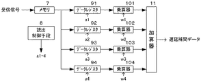
図3に、図2における第1チャンネル遅延回路31のブロック図を示す。A/D変換器21によってデジタル信号に変換された受信信号は、A/D変換器のサンプリング間隔ΔTのデータとしてメモリ7に保存される。そして、ある目的時間T0から、前記サンプリング間隔ΔTの整数倍の時間T1と、T1よりも小さいτ1だけずれた時刻の近傍にサンプリング時刻を持つ4つのデジタルデータが、メモリ7より読み出されデータレジスタ91〜94に保存される。そして、乗算器101〜104は、メモリ7に保存された4つのデジタルデータに、所定の重み係数w1〜w4を乗算する。加算器11は、デジタルデータに所定の重みを乗算したものを加算することにより、遅延補間データを算出する。
FIG. 3 is a block diagram of the first
ここで、所定の重み係数w1〜w4には混合スプライン補間の補間係数がそれぞれ設定されており、補間係数を適切に設定することにより、仮想時間をT1+τ1だけ前の時刻に設定できることが記載されている。 Here, it is described that the interpolation coefficients of the mixed spline interpolation are set for the predetermined weighting coefficients w1 to w4, respectively, and that the virtual time can be set to the previous time by T1 + τ1 by appropriately setting the interpolation coefficients. Yes.
このように、特許文献1では、混合スプライン補間を用いて、サンプリング時刻のデータのうち、補間点前後の4点のデータを用いて、遅延補間データを算出することが開示されている。 As described above, Patent Document 1 discloses that, using mixed spline interpolation, delay interpolation data is calculated using data at four points before and after the interpolation point among sampling time data.
しかしながら、前記従来の構成では、目的とする時刻tkにおけるデジタルデータを求める際には、サンプリング時刻tk近傍の4点のデータを用いて補間や混合スプライン補間を用いているため、特に超音波領域のような高い周波数において、隣接する点の値が大きく異なるような場合には、精度が落ちるという課題を有していた。 However, in the conventional configuration, when digital data at the target time tk is obtained, interpolation or mixed spline interpolation is used using four points of data near the sampling time tk. In such a high frequency, when the values of adjacent points are greatly different, there is a problem that accuracy is lowered.
本発明は、前記従来の課題を解決するもので、従来と比べて、演算量を抑制しながらより精度の高い整層加算処理を実行するビームフォーマ、及び前記ビームフォーマを搭載した超音波診断装置を提供することを目的とする。 The present invention solves the above-described conventional problems. Compared to the conventional technique, the present invention solves the above-described problem, and performs a stratified addition process with higher accuracy while suppressing the amount of calculation. The purpose is to provide.
前記従来の課題を解決するために、本発明の超音波診断装置は、複数の受信素子を有する超音波プローブと、前記超音波プローブから得られた受信信号に対して、所定のサンプリング間隔ΔTでサンプリングを行い、時系列デジタルデータを生成するA/D変換器と、前記A/D変換器で生成されたデジタルデータを記憶するメモリと、前記デジタルデータに対して遅延処理を行うビームフォーム部と、を有し、前記ビームフォーム部は、受信フォーカス点と受信素子の位置から遅延時間を算出する遅延算出部と、前記受信フォーカス点からの受信信号のアドレスであるフォーカス位置アドレスと前記メモリから前記デジタルデータを読み出す読み出し開始アドレスを指定し、前記フォーカス位置アドレスを含むようにデジタルデータのアドレスを選択するアドレスコントローラと、選択される前記デジタルデータに対応する補正係数を算出する係数算出部を備える遅延制御部と、前記選択されたアドレスに対応するデジタルデータに対して、オールパスフィルタ処理を行うオールパスフィルタ処理部、を備えることを特徴とする。 In order to solve the above-described conventional problems, an ultrasonic diagnostic apparatus of the present invention includes an ultrasonic probe having a plurality of receiving elements and a reception signal obtained from the ultrasonic probe at a predetermined sampling interval ΔT. An A / D converter that performs sampling and generates time-series digital data; a memory that stores digital data generated by the A / D converter; and a beamform unit that performs a delay process on the digital data; the a, the beam form unit, said a delay calculator for calculating a delay time between reception focus point from the position of the receiving element, from the focus position address memory the address of the reception signal from the reception focusing point specify the read start address for reading the digital data, add the digital data to include the focus position address An address controller for selecting a source, a delay control unit including a coefficient calculation unit for calculating a correction coefficient corresponding to the selected digital data, and an all-pass filter process for the digital data corresponding to the selected address. An all-pass filter processing unit is provided.
本構成によって、正確な遅延処理を行うオールパスフィルタ処理をすることにより、精度の高い整相加算処理を実行することができる。 With this configuration, a highly accurate phasing addition process can be performed by performing an all-pass filter process for performing an accurate delay process.
また、本発明の超音波診断装置は、前記オールパスフィルタ処理部におけるオールパスフィルタが1次のオールパスフィルタであるという特徴を有する。 In the ultrasonic diagnostic apparatus of the present invention, the all-pass filter in the all-pass filter processing unit is a primary all-pass filter.
本構成によって、オールパスフィルタ処理の演算量を少なくすることができる。 With this configuration, the calculation amount of the all-pass filter process can be reduced.
また、本発明の超音波診断装置は、前記アドレスコントローラは、前記フォーカス位置アドレスに対応するデジタルデータが、前記選択されるデジタルデータの最終アドレスに位置するように、前記アドレスを指定するという特徴を有する。 The ultrasonic diagnostic apparatus of the present invention is characterized in that the address controller designates the address so that digital data corresponding to the focus position address is located at a final address of the selected digital data. Have.
本構成によって、通常のフォーカス点1点で遅延加算を行うような場合にフォーカス点におけるデータの精度が増す。 With this configuration, the accuracy of data at the focus point is increased when delay addition is performed at one normal focus point.
また、本発明の超音波診断装置は、前記アドレスコントローラは、前記フォーカス位置アドレスに対応するデジタルデータが、前記選択されるデジタルデータの略中央位置に存在するようにアドレスを指定するという特徴を有する。 The ultrasonic diagnostic apparatus of the present invention is characterized in that the address controller designates an address so that digital data corresponding to the focus position address is present at a substantially central position of the selected digital data. .
本構成によって、読み出されるデータを全て使用する場合に最も精度がよくなる。 This configuration provides the best accuracy when all the data to be read is used.
また、本発明の超音波診断装置は、前記アドレスコントローラは、前記フォーカス位置アドレスに対応するデジタルデータが、前記選択されるデジタルデータの中心位置よりも後半に位置するように、前記アドレスを指定するという特徴を有する。 In the ultrasonic diagnostic apparatus of the present invention, the address controller designates the address so that digital data corresponding to the focus position address is located in the latter half of the center position of the selected digital data. It has the characteristics.
本構成によって、フォーカス点近傍の複数の点を使用する場合に精度がよくなる。 This configuration improves the accuracy when using a plurality of points near the focus point.
また、本発明の超音波診断装置は、前記アドレスコントローラは、前記遅延時間に基づいて、指定するデジタルデータの長さが変化するようにアドレスを指定するという特徴を有する。 The ultrasonic diagnostic apparatus of the present invention is characterized in that the address controller designates an address based on the delay time so that the length of designated digital data changes.
本構成によって、オールパスフィルタに使用するデータ数をオールパスフィルタの係数によって変更することが可能となる。 With this configuration, the number of data used for the all-pass filter can be changed by the coefficient of the all-pass filter.
また、本発明の超音波診断装置は、前記アドレスコントローラは、前記遅延時間の小数部分が第1遅延時間の方が第2遅延時間よりも大きい場合、前記第1遅延時間に対して選択するデジタルデータの長さが、前記第2遅延時間に対して選択するデジタルデータの長さよりも長くなるように前記アドレスを指定するという特徴を有する。 In the ultrasonic diagnostic apparatus according to the present invention, the address controller may select the first delay time when the decimal part of the delay time is larger than the second delay time when the first delay time is larger than the second delay time. The address is designated such that the length of the data is longer than the length of the digital data selected for the second delay time.
本構成によって、オールパスフィルタ処理の演算量を効率的にすることができる。 With this configuration, the calculation amount of the all-pass filter process can be made efficient.
また、本発明の超音波診断装置は、前記遅延時間の小数部分が0.95以上の場合に、前記係数算出部は補正係数を0とし、前記オールパスフィルタ処理部は整数部の遅延量を+1とするという特徴を有する。 In the ultrasonic diagnostic apparatus of the present invention, when the fractional part of the delay time is 0.95 or more, the coefficient calculation unit sets the correction coefficient to 0, and the all-pass filter processing unit sets the delay amount of the integer part to +1. It has the feature that.
本構成によって、オールパスフィルタの正確な値を求めるために演算量が必要となる部分において演算量を少なくすることができる。 With this configuration, it is possible to reduce the amount of calculation in a portion where the amount of calculation is required to obtain an accurate value of the all-pass filter.
本発明の精密な遅延制御部を有するビームフォーマによれば、従来に比べて精度の高い整相加算処理をすることができる。そのため、本ビームフォーマを用いて整相加算された信号を用いて画像生成を行う超音波装置において、超音波画像の画質を改善することが可能になる。 According to the beamformer having the precise delay control unit of the present invention, it is possible to perform phasing addition processing with higher accuracy than in the past. Therefore, it is possible to improve the image quality of an ultrasonic image in an ultrasonic apparatus that generates an image using a signal subjected to phasing addition using this beamformer.
以下本発明の実施の形態について、図面を参照しながら説明する。 Embodiments of the present invention will be described below with reference to the drawings.
(実施の形態1)
図2は、本発明の実施の形態1における超音波診断装置のブロック図である。
(Embodiment 1)
FIG. 2 is a block diagram of the ultrasonic diagnostic apparatus according to Embodiment 1 of the present invention.
プローブ1から入力されたアナログの超音波信号は、A/D変換器21〜2nによって、アナログ信号からデジタル信号に変換される。そして、第1チャンネル遅延回路31から第nチャンネル遅延回路3nまでの遅延回路は、デジタル信号に変換された受信信号を位相調整し、加算回路4で加算することによりビームフォーミングを行う。このようにして、音線信号を生成し、信号処理部5で音線信号から画像への変換処理を行い、表示部6で超音波画像を表示する構成になっている。
The analog ultrasonic signal input from the probe 1 is converted from an analog signal to a digital signal by the A /
超音波診断装置は、フォーカス点を、受信素子の近傍から深部まで走査しながら受信ダイナミックフォーカス処理を行い、超音波診断装置で描画する音線信号の1ラインを生成する。 The ultrasonic diagnostic apparatus performs reception dynamic focus processing while scanning the focus point from the vicinity of the receiving element to the deep part, and generates one line of the sound ray signal to be drawn by the ultrasonic diagnostic apparatus.
ここで、遅延回路で位相調整を行う受信ダイナミックフォーカス処理について図4と図5を用いて説明する。開口中心から距離a離れているフォーカス点を複数の受信素子信号を用いて描画する場合、フォーカス点から各受信素子までの遅延量を求める。例えば開口中心にある受信素子bが最も早く受信信号を受ける(4図右上の(b)参照)。最も端の受信素子cでは受信素子bに比べて時間dだけ遅れて受信信号を受け取る(図4右中の(c)参照)。この場合、受信信号bをdだけ遅らせて図4(d)に示す信号と図4(c)に示す信号を加算すると、二つの信号の位相が同相となり、受信信号のレベルを大きくすることができる。遅延処理は、このように、フォーカス点の位置と受信素子の位置関係(距離)から各受信素子が受信した信号の遅延量を算出し、その遅延量分だけ信号を遅らせて加算することで、小さい反射信号を大きくする。 Here, the reception dynamic focus processing in which the phase adjustment is performed by the delay circuit will be described with reference to FIGS. When a focus point that is a distance a from the center of the aperture is drawn using a plurality of reception element signals, a delay amount from the focus point to each reception element is obtained. For example, the receiving element b at the center of the aperture receives the received signal earliest (see (b) in the upper right of FIG. 4). The farthest receiving element c receives the received signal with a delay of time d compared to the receiving element b (see (c) in the middle right of FIG. 4). In this case, if the received signal b is delayed by d and the signal shown in FIG. 4D and the signal shown in FIG. 4C are added, the phases of the two signals become in-phase, and the level of the received signal can be increased. it can. In this way, the delay processing calculates the delay amount of the signal received by each receiving element from the position of the focus point and the positional relationship (distance) of the receiving element, and delays and adds the signal by the delay amount, Increase the small reflected signal.
ここで受信信号はデジタルデータであるため、遅延量の理論値dが小数点まで持つような場合、例えば6.4サンプルといった場合(図5の白○が遅延量の理論値を示す点、●はサンプリング点を示す)には、通常は6サンプル目のデジタル信号を近似して用いる、もしくは、補間処理などを用いて、隣接する2点のサンプリング点の値を用いる等をして、6.4サンプル目の値を補間計算により算出していた。そのため、正確な遅延処理を行うことができなかった。 Here, since the received signal is digital data, when the theoretical value d of the delay amount has a decimal point, for example, 6.4 samples (the white circle in FIG. 5 indicates the theoretical value of the delay amount, In general, the digital signal of the sixth sample is approximated or used, or the values of two adjacent sampling points are used by using an interpolation process or the like. The value of the sample was calculated by interpolation calculation. Therefore, accurate delay processing cannot be performed.
本実施の形態では、整相加算処理の精度を向上させるために、受信データに対してオールパスフィルタ処理を行う。オールパスフィルタは、振幅特性はそのままで、位相特性のみを変化させるフィルタである。オールパスフィルタを用いることで、サンプリング周波数の整数倍の点(以下、サンプリング点)から、サンプリング周期以下だけずれた遅延値(以下、小数点部分と呼ぶ)に対応する位相を変化させることによって、より適切に遅延処理を行うことが可能になる。 In the present embodiment, all-pass filter processing is performed on received data in order to improve the accuracy of the phasing addition processing. The all-pass filter is a filter that changes only the phase characteristic without changing the amplitude characteristic. By using an all-pass filter, it is more appropriate to change the phase corresponding to the delay value (hereinafter referred to as the decimal part) that is shifted by a sampling period or less from a point that is an integral multiple of the sampling frequency (hereinafter referred to as the sampling point). It is possible to perform delay processing.
しかし、オールパスフィルタ処理を行うことにより、遅延処理の精度は上がるが、整相加算に要する計算量が増大してしまう。特に、超音波診断装置の場合は、近距離を見るため、信号が球面波領域である。そのためフォーカス点ごとにオールパスフィルタ処理を行うことが必要になる。よって、非常に計算量が増大してしまうという問題が発生する。なおフォーカス点とは超音波診断装置で描画を行う各描画点を意味する。 However, performing all-pass filtering increases the accuracy of delay processing, but increases the amount of calculation required for phasing addition. In particular, in the case of an ultrasonic diagnostic apparatus, the signal is a spherical wave region in order to see a short distance. Therefore, it is necessary to perform an all-pass filter process for each focus point. Therefore, there arises a problem that the calculation amount is greatly increased. The focus point means each drawing point where drawing is performed by the ultrasonic diagnostic apparatus.
そこで、本発明のビームフォーム部は、フォーカス点のアドレスを利用して、オールパスフィルタ処理を行うデータを決定する。 Therefore, the beamform unit of the present invention uses the focus point address to determine data to be subjected to all-pass filtering.
図1は、本発明の実施の形態1におけるビームフォーム部(遅延回路)のブロック図である。ビームフォーム部は、A/D変換器から入力されたデジタル受信信号が格納されるメモリ7と、オールパスフィルタ処理を行うデジタルデータを格納するデータレジスタ13と、データレジスタ13に格納されたデータを受け取り、オールパスフィルタ処理を行うAPF部(もしくはオールパスフィルタ処理部、と呼ぶ)14と、APF部14によって処理されたデータが保存されるデータレジスタ部15を有する構成となっている。
FIG. 1 is a block diagram of a beamform unit (delay circuit) according to Embodiment 1 of the present invention. The beamform unit receives the
ここで、ビームフォーム部は、遅延制御部12を有し、遅延制御部12は受信素子位置及びフォーカス点から、フォーカス点のメモリアドレス値、及び、読み出し開始アドレスを算出する。また、遅延制御部12は、データレジスタに格納されるデータに対して使用されるオールパスフィルタ係数w1を算出する。APF部14は遅延制御部12によって算出されたオールパスフィルタ係数w1を使用してオールパスフィルタ処理が行われる。
Here, the beamform unit includes a
次に図5、図6、図7を用いて、実際の動作について説明を行う。 Next, the actual operation will be described with reference to FIGS.
図6に、遅延制御部12の構成を図示する。
FIG. 6 illustrates the configuration of the
遅延制御部12は、遅延算出部121を有し、遅延算出部121は、各受信素子における理論遅延量を、フォーカス点及び受信素子位置の位置関係、具体的にはフォーカス点と受信素子の間の距離に応じてサンプル単位で求める。この時の理論遅延量は、小数点以下の値も持っていることになる。
The
次に、遅延算出部121において算出された遅延量のうち、小数部が、1.0より減算される。例えば小数部が0.4の場合は0.6となる(1.0−0.4=0.6)。次に、この処理遅延量(例では0.6)となるようなオールパスフィルタの係数(w1)をAPF係数算出部123より算出する。オールパスフィルタの係数は、演算量の余裕により、1次のオールパスフィルタだけでなく2次以上のオールパスフィルタとしてもよい。次数を増やすことで、より高精度の遅延処理が可能となる。また、オールパスフィルタの係数はある精度であらかじめ求めて(例えば0〜1の間を256で分割するなど)テーブル化しておき、入力された遅延量に応じてあらかじめ求めた値を設定してもよい。このことにより、係数算出の演算量を削減することができる。
Next, the fractional part of the delay amount calculated by the
APF部14では、オールパスフィルタで処理した遅延量分だけ、入力データを遅らせる。図5(a)はオールパスフィルタ処理をする前のデータ、図5の(b)はオールパスフィルタ処理をした後のデータを示す一例である。6.4サンプルの位置にあった値がオールパスフィルタによって7サンプルの位置に配置される。このことにより、小数点以下の遅延がなくなる。
The
アドレスコントローラ122は、遅延算出部121で算出された理論遅延量の整数部の値に、オールパスフィルタで増加した遅延量+1を加算して、フォーカス点のデジタルデータに対応するアドレス位置(af)を算出する。アドレスコントローラでは、算出されたフォーカス点のアドレス位置afからメモリ7より受信データを読出す時の先頭となる、読出先頭アドレス位置を算出する。オールパスフィルタに使用するデータ数がnとすると、ビームフォーミングの処理が遅延加算処理である場合は、読出先頭アドレスa1は、
a1=af−n+1
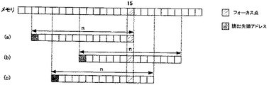
で、算出される。このように、読出先頭アドレスを設定すると、図7(a)に示すように、フォーカス点に対応するデジタルデータが,データレジスタ13に格納されたデータのうち最終アドレスに位置する。オールパスフィルタ処理では、最初の点から徐々に収束して真値に近づいていくため、データレジスタの最後の点の位置で最も収束する。そのため、フォーカス点に対応するデジルデータがオールパスフィルタ処理を行うデータの最後段に配置されることにより、より真値に近づくという特有の効果を奏することができる。
The
a1 = af−n + 1
Is calculated. As described above, when the read head address is set, the digital data corresponding to the focus point is located at the last address among the data stored in the data register 13 as shown in FIG. In the all-pass filter process, since convergence gradually approaches the true value from the first point, it converges most at the position of the last point of the data register. Therefore, by arranging the digital data corresponding to the focus point at the last stage of the data to be subjected to the all-pass filter processing, it is possible to achieve a unique effect of approaching the true value.
また、図7(b)のように、オールパスフィルタ処理を行うデータの略中央にフォーカス点が位置するようにしてもよい。このようにフォーカス点のデジタルデータを配置することで図7(a)に比べて収束はしていないが、フォーカス点の前後のデジタルデータ、特にデータレジスタの全データを使用する場合には最も効率的な構成となる。 Further, as shown in FIG. 7B, the focus point may be positioned at the approximate center of the data to be subjected to the all-pass filter processing. The arrangement of the focus point digital data does not converge as compared with FIG. 7A, but it is most efficient when digital data before and after the focus point, in particular, all data in the data register is used. It becomes a typical configuration.
また、図7(c)に示すように、フォーカス点に対応するデジタルデータを、オールパスフィルタ処理を行うデータの中央より後段に配置してもよい。この構成により、収束したフォーカス点の前後のデジタルデータを利用することが可能になる。 Further, as shown in FIG. 7C, the digital data corresponding to the focus point may be arranged at the subsequent stage from the center of the data to be subjected to the all-pass filter processing. With this configuration, digital data before and after the converged focus point can be used.
なお、前述の形態では、アドレスコントローラ122は、フォーカス点のデジタルデータに対応するアドレスと、読出データのアドレスの両方を指定している。しかし、アドレスコントローラ122は、データ数のみを指定するものであってもよい。いずれにせよ、指定されるデータのアドレスが、フォーカス点に対応するデジタルデータのアドレスを含むものであれば、アドレスコントローラ122の詳細設定はいずれか一つの方式に限られるものではない。
In the above-described form, the
なお、アドレスコントローラ122で選択するデジタルデータ数は、およそ15〜20tapが好ましい。デジタルデータ数を増加させると、遅延処理の精度は向上するが、計算量が増大する。求められる遅延処理の精度及び計算量の両方を鑑みて、データ数nを適宜設定することが好ましい。
The number of digital data selected by the
このようにフォーカス位置のアドレスafと、読出し開始アドレスa1がアドレスコントローラ122で算出されると、メモリ7より上記アドレスに応じてデータがデータレジスタ13に格納される。また、APF係数算出部123より算出されたAPF係数がAPF14に設定される。APF部14は、データレジスタ13に設定されたデータとAPF係数によってAPF処理を実行し、遅延処理後のデータがデータレジスタ15に格納される。例えば、図7(a)に示すように、オールパスフィルタが行われるデジタルデータの再後段にフォーカス点のデジタルデータが設定されていた場合、最終遅延データはデータレジスタ15の最終データとして出力される。なお、データレジスタ13と15は同じ領域を用いてもよい。
As described above, when the address af of the focus position and the read start address a1 are calculated by the
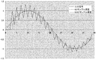
オールパスフィルタの特性として、遅延量が少ない場合は、収束が早く、遅延量が多いと収束が遅くなるという特性がある。図8に遅延量の違いによるオールパスフィルタの出力を示す。ただし収束度合いを見やすくするためにディレイ量を合わせている。図8を見ると、遅延量が多くなるほど収束が遅くなっており、特に遅延量が1.0に近づくと収束が遅くなっていくことが分かる。このことから、オールパスフィルタで遅延処理を行うデータ数を遅延量によって変化させてもよい。例えば0.1タップなどでは遅延量が少ないため5サンプル,また0.9などの場合は20サンプルとするというように可変にしてもよい。すなわち、なお、アドレスコントローラは、遅延時間の小数点部分が第1の遅延時間の方が第2の遅延時間(第1の遅延時間とは異なる値)よりも大きい場合、第1の遅延時間に対して選択するデジタルデータの長さを、第2の遅延時間に対して選択するデジタルデータの長さよりも長くなるようにアドレスを指定してもよい。 As a characteristic of the all-pass filter, when the delay amount is small, the convergence is fast, and when the delay amount is large, the convergence is slow. FIG. 8 shows the output of the all-pass filter depending on the delay amount. However, the delay amount is adjusted to make the degree of convergence easier to see. As can be seen from FIG. 8, the convergence is delayed as the delay amount is increased, and the convergence is delayed as the delay amount approaches 1.0. For this reason, the number of data to be delayed by the all-pass filter may be changed according to the delay amount. For example, the delay amount is small for 0.1 taps and the like, and may be variable such that 5 samples are used, and 20 samples are used for 0.9 taps. That is, the address controller determines that the first delay time is greater than the first delay time when the decimal point portion of the delay time is greater than the second delay time (a value different from the first delay time). The address may be specified so that the length of the digital data to be selected is longer than the length of the digital data to be selected for the second delay time.
なお、小数点部分の遅延量が大きくなるほど(1に近づくほど)、遅延処理を行うデータサンプル数(データレジスタ13に格納するデータ数)を大きく設定してもよい。 Note that the larger the amount of delay in the decimal part (the closer it is to 1), the larger the number of data samples to be subjected to delay processing (the number of data stored in the data register 13) may be set.
このように小数点部分の遅延量によって、データサンプル数を変化させることにより、よりオールパスフィルタの収束が終了した状態で遅延データを算出することが可能になる。 In this way, by changing the number of data samples according to the delay amount of the decimal part, it is possible to calculate delay data in a state where the convergence of the all-pass filter has been completed.
また、1.0サンプルに非常に近い0.95サンプル以上では、収束までにかかる時間が非常に長くなる。図9に遅延量と収束するために必要なタップ数を示す。特に0.95サンプル以上となると20タップ以上のデータ数が必要となる。そこで、0.95サンプル以上の遅延があった場合は、APF係数算出部123は、係数を0に設定し、整数部分の遅延量を1増加させてもよい。このようにすることで少ない演算量で効率よく演算を行うことができる。
Also, at 0.95 samples or more, which is very close to 1.0 samples, the time required for convergence becomes very long. FIG. 9 shows the delay amount and the number of taps necessary for convergence. In particular, when the number of samples is 0.95 or more, the number of data of 20 taps or more is required. Therefore, when there is a delay of 0.95 samples or more, the APF
かかる構成によれば遅延回路をオールパスフィルタで処理することにより、小数以下の遅延処理も行える遅延回路を有するため、従来に比べて精度の高い整相加算ができることから画質の高い超音波診断装置を提供することができる。 According to such a configuration, since the delay circuit can be processed with an all-pass filter, the delay circuit can also perform a delay process of a decimal number or less, so that a highly accurate phasing addition can be performed as compared with the conventional one. Can be provided.
(その他変形例)
なお、本発明を上記実施の形態に基づいて説明してきたが、本発明は、上記の実施の形態に限定されないのはもちろんである。以下のような場合も本発明に含まれる。
(Other variations)
Although the present invention has been described based on the above embodiment, it is needless to say that the present invention is not limited to the above embodiment. The following cases are also included in the present invention.
(1)上記の各装置は、具体的には、マイクロプロセッサ、ROM、RAM、ハードディスクユニット、ディスプレイユニット、キーボード、マウスなどから構成されるコンピュータシステムである。前記RAMまたはハードディスクユニットには、コンピュータプログラムが記憶されている。前記マイクロプロセッサが、前記コンピュータプログラムにしたがって動作することにより、各装置は、その機能を達成する。ここでコンピュータプログラムは、所定の機能を達成するために、コンピュータに対する指令を示す命令コードが複数個組み合わされて構成されたものである。 (1) Each of the above devices is specifically a computer system including a microprocessor, a ROM, a RAM, a hard disk unit, a display unit, a keyboard, a mouse, and the like. A computer program is stored in the RAM or hard disk unit. Each device achieves its functions by the microprocessor operating according to the computer program. Here, the computer program is configured by combining a plurality of instruction codes indicating instructions for the computer in order to achieve a predetermined function.
(2)上記の各装置を構成する構成要素の一部または全部は、1個のシステムLSI(Large Scale Integration:大規模集積回路)から構成されているとしてもよい。システムLSIは、複数の構成部を1個のチップ上に集積して製造された超多機能LSIであり、具体的には、マイクロプロセッサ、ROM、RAMなどを含んで構成されるコンピュータシステムである。前記RAMには、コンピュータプログラムが記憶されている。前記マイクロプロセッサが、前記コンピュータプログラムにしたがって動作することにより、システムLSIは、その機能を達成する。 (2) A part or all of the constituent elements constituting each of the above-described devices may be configured by one system LSI (Large Scale Integration). The system LSI is an ultra-multifunctional LSI manufactured by integrating a plurality of components on a single chip, and specifically, a computer system including a microprocessor, ROM, RAM, and the like. . A computer program is stored in the RAM. The system LSI achieves its functions by the microprocessor operating according to the computer program.
(3)上記の各装置を構成する構成要素の一部または全部は、各装置に脱着可能なICカードまたは単体のモジュールから構成されているとしてもよい。前記ICカードまたは前記モジュールは、マイクロプロセッサ、ROM、RAMなどから構成されるコンピュータシステムである。前記ICカードまたは前記モジュールは、上記の超多機能LSIを含むとしてもよい。マイクロプロセッサが、コンピュータプログラムにしたがって動作することにより、前記ICカードまたは前記モジュールは、その機能を達成する。このICカードまたはこのモジュールは、耐タンパ性を有するとしてもよい。 (3) Part or all of the constituent elements constituting each of the above devices may be configured from an IC card that can be attached to and detached from each device or a single module. The IC card or the module is a computer system including a microprocessor, a ROM, a RAM, and the like. The IC card or the module may include the super multifunctional LSI described above. The IC card or the module achieves its function by the microprocessor operating according to the computer program. This IC card or this module may have tamper resistance.
(4)本発明は、上記に示す方法であるとしてもよい。また、これらの方法をコンピュータにより実現するコンピュータプログラムであるとしてもよいし、前記コンピュータプログラムからなるデジタル信号であるとしてもよい。 (4) The present invention may be the method described above. Further, the present invention may be a computer program that realizes these methods by a computer, or may be a digital signal composed of the computer program.
また、本発明は、前記コンピュータプログラムまたは前記デジタル信号をコンピュータ読み取り可能な記録媒体、例えば、フレキシブルディスク、ハードディスク、CD−ROM、MO、DVD、DVD−ROM、DVD−RAM、BD(Blu−ray Disc)、半導体メモリなどに記録したものとしてもよい。また、これらの記録媒体に記録されている前記デジタル信号であるとしてもよい。 The present invention also provides a computer-readable recording medium such as a flexible disk, hard disk, CD-ROM, MO, DVD, DVD-ROM, DVD-RAM, BD (Blu-ray Disc). ), Recorded in a semiconductor memory or the like. The digital signal may be recorded on these recording media.
また、本発明は、前記コンピュータプログラムまたは前記デジタル信号を、電気通信回線、無線または有線通信回線、インターネットを代表とするネットワーク、データ放送等を経由して伝送するものとしてもよい。 In the present invention, the computer program or the digital signal may be transmitted via an electric communication line, a wireless or wired communication line, a network represented by the Internet, a data broadcast, or the like.
また、本発明は、マイクロプロセッサとメモリを備えたコンピュータシステムであって、前記メモリは、上記コンピュータプログラムを記憶しており、前記マイクロプロセッサは、前記コンピュータプログラムにしたがって動作するとしてもよい。 The present invention may be a computer system including a microprocessor and a memory, wherein the memory stores the computer program, and the microprocessor operates according to the computer program.
また、前記プログラムまたは前記デジタル信号を前記記録媒体に記録して移送することにより、または前記プログラムまたは前記デジタル信号を前記ネットワーク等を経由して移送することにより、独立した他のコンピュータシステムにより実施するとしてもよい。 In addition, the program or the digital signal is recorded on the recording medium and transferred, or the program or the digital signal is transferred via the network or the like, and executed by another independent computer system. It is good.
(5)上記実施の形態及び上記変形例をそれぞれ組み合わせるとしてもよい。 (5) The above embodiment and the above modifications may be combined.
本発明にかかる超音波診断装置は、小数以下の遅延処理も行える遅延回路を有し、精度の高い整相加算ができるため画質向上として有用である。 The ultrasonic diagnostic apparatus according to the present invention has a delay circuit that can also perform a delay process of a decimal or less, and can perform highly accurate phasing addition, which is useful for improving image quality.
1 プローブ
21,2n A/D変換器
31 第1チャンネル遅延回路
3n 第nチャンネル遅延回路
4 加算回路
5 信号処理部
6 表示部
7 メモリ
8 読出制御手段
13,15,91,92,93,94 データレジスタ
101,102,103,104 乗算器
11 加算器
12 遅延制御部
121 遅延算出部
122 アドレスコントローラ
123 APF係数算出部
DESCRIPTION OF SYMBOLS 1
Claims (8)
前記超音波プローブから得られた受信信号に対して、所定のサンプリング間隔ΔTでサンプリングを行い、時系列デジタルデータを生成するA/D変換器と、
前記A/D変換器で生成されたデジタルデータを記憶するメモリと、
前記デジタルデータに対して遅延処理を行うビームフォーム部と、を有し、
前記ビームフォーム部は、
受信フォーカス点と受信素子の位置から遅延時間を算出する遅延算出部と、
前記受信フォーカス点からの受信信号のアドレスであるフォーカス位置アドレスと前記メモリから前記デジタルデータを読み出す読み出し開始アドレスを指定し、前記フォーカス位置アドレスを含むようにデジタルデータのアドレスを選択するアドレスコントローラと、
選択される前記デジタルデータに対応する補正係数を算出する係数算出部を備える遅延制御部と、
前記選択されたアドレスに対応するデジタルデータに対して、オールパスフィルタ処理を行うオールパスフィルタ処理部と、
を備えることを特徴とする超音波診断装置。 An ultrasonic probe having a plurality of receiving elements;
An A / D converter that samples the received signal obtained from the ultrasonic probe at a predetermined sampling interval ΔT and generates time-series digital data;
A memory for storing digital data generated by the A / D converter;
A beamform unit for performing a delay process on the digital data,
The beamform part is
A delay calculation unit that calculates a delay time from the position of the reception focus point and the reception element;
An address controller that specifies a focus position address that is an address of a reception signal from the reception focus point and a read start address for reading the digital data from the memory, and selects an address of the digital data so as to include the focus position address;
A delay control unit comprising a coefficient calculation unit for calculating a correction coefficient corresponding to the selected digital data;
An all-pass filter processing unit that performs all-pass filter processing on the digital data corresponding to the selected address;
An ultrasonic diagnostic apparatus comprising:
Priority Applications (1)
| Application Number | Priority Date | Filing Date | Title |
|---|---|---|---|
| JP2011075022A JP5672111B2 (en) | 2011-03-30 | 2011-03-30 | Ultrasonic diagnostic equipment |
Applications Claiming Priority (1)
| Application Number | Priority Date | Filing Date | Title |
|---|---|---|---|
| JP2011075022A JP5672111B2 (en) | 2011-03-30 | 2011-03-30 | Ultrasonic diagnostic equipment |
Publications (2)
| Publication Number | Publication Date |
|---|---|
| JP2012205825A JP2012205825A (en) | 2012-10-25 |
| JP5672111B2 true JP5672111B2 (en) | 2015-02-18 |
Family
ID=47186149
Family Applications (1)
| Application Number | Title | Priority Date | Filing Date |
|---|---|---|---|
| JP2011075022A Expired - Fee Related JP5672111B2 (en) | 2011-03-30 | 2011-03-30 | Ultrasonic diagnostic equipment |
Country Status (1)
| Country | Link |
|---|---|
| JP (1) | JP5672111B2 (en) |
Families Citing this family (1)
| Publication number | Priority date | Publication date | Assignee | Title |
|---|---|---|---|---|
| JP6400433B2 (en) * | 2014-10-31 | 2018-10-03 | キヤノンメディカルシステムズ株式会社 | Ultrasonic diagnostic apparatus, interpolation processing unit, and interpolation processing method |
Family Cites Families (2)
| Publication number | Priority date | Publication date | Assignee | Title |
|---|---|---|---|---|
| JPS63222745A (en) * | 1987-03-13 | 1988-09-16 | 松下電器産業株式会社 | Ultrasonic diagnostic apparatus |
| US5844139A (en) * | 1996-12-30 | 1998-12-01 | General Electric Company | Method and apparatus for providing dynamically variable time delays for ultrasound beamformer |
-
2011
- 2011-03-30 JP JP2011075022A patent/JP5672111B2/en not_active Expired - Fee Related
Also Published As
| Publication number | Publication date |
|---|---|
| JP2012205825A (en) | 2012-10-25 |
Similar Documents
| Publication | Publication Date | Title |
|---|---|---|
| US11360199B2 (en) | Ultrasound signal processing device, ultrasound diagnostic device | |
| KR101118515B1 (en) | The apparatus of beamforming the ultrasound signal and the method using it | |
| JP4039643B2 (en) | Ultrasonic beam forming device | |
| CN108209971B (en) | Ultrasonic signal processing apparatus and method, and ultrasonic diagnostic apparatus | |
| JP2008149139A (en) | Device and method for forming beam based on fractional delay filter using post filtering | |
| JPH0562495A (en) | Sampling frequency converter | |
| US10743842B2 (en) | Ultrasound signal processor, ultrasound signal processing method, and ultrasound diagnostic device | |
| JP2007313319A (en) | Ultrasonic diagnostic system and method for forming multiple receiving scan line | |
| JP5672111B2 (en) | Ultrasonic diagnostic equipment | |
| WO2015194253A1 (en) | Ultrasonic diagnostic device | |
| JP5085691B2 (en) | Ultrasonic diagnostic equipment | |
| JP7099162B2 (en) | Ultrasonic signal processing method and ultrasonic signal processing device | |
| JP2017064249A (en) | Ultrasonic diagnostic equipment and delay data generation method | |
| JP5412604B1 (en) | Ultrasonic diagnostic apparatus and beam forming method | |
| JPWO2016129376A1 (en) | Ultrasonic imaging apparatus, inter-transmission weight adjustment method, and ultrasonic imaging method | |
| US11129595B2 (en) | Ultrasonic diagnostic apparatus, interpolation processing unit, and interpolation processing method | |
| KR101160959B1 (en) | Method and apparatus of interpolating delay in ultrasound beamformer | |
| KR101442221B1 (en) | Multi beam former apparatus and method using polyphase interpolation filter | |
| JP6825474B2 (en) | Ultrasonic diagnostic equipment and ultrasonic signal processing method. | |
| JP5895571B2 (en) | Ultrasonic diagnostic equipment | |
| JP5661489B2 (en) | Ultrasonic diagnostic equipment | |
| JP2015037535A (en) | Ultrasonic signal processor, ultrasonic signal processing method and computer-readable non-temporary recording medium | |
| JP2004283265A (en) | Ultrasonic diagnostic equipment | |
| KR101135065B1 (en) | Method and apparatus of forming multiple scanning lines | |
| JP7020052B2 (en) | Ultrasound signal processing device, ultrasonic diagnostic device, ultrasonic signal processing method, and ultrasonic image display method |
Legal Events
| Date | Code | Title | Description |
|---|---|---|---|
| A711 | Notification of change in applicant |
Free format text: JAPANESE INTERMEDIATE CODE: A711 Effective date: 20140121 |
|
| RD02 | Notification of acceptance of power of attorney |
Free format text: JAPANESE INTERMEDIATE CODE: A7422 Effective date: 20140205 |
|
| A621 | Written request for application examination |
Free format text: JAPANESE INTERMEDIATE CODE: A621 Effective date: 20140213 |
|
| RD02 | Notification of acceptance of power of attorney |
Free format text: JAPANESE INTERMEDIATE CODE: A7422 Effective date: 20140613 |
|
| A977 | Report on retrieval |
Free format text: JAPANESE INTERMEDIATE CODE: A971007 Effective date: 20140924 |
|
| A131 | Notification of reasons for refusal |
Free format text: JAPANESE INTERMEDIATE CODE: A131 Effective date: 20140930 |
|
| A521 | Request for written amendment filed |
Free format text: JAPANESE INTERMEDIATE CODE: A523 Effective date: 20141105 |
|
| TRDD | Decision of grant or rejection written | ||
| A01 | Written decision to grant a patent or to grant a registration (utility model) |
Free format text: JAPANESE INTERMEDIATE CODE: A01 Effective date: 20141125 |
|
| A61 | First payment of annual fees (during grant procedure) |
Free format text: JAPANESE INTERMEDIATE CODE: A61 Effective date: 20141208 |
|
| R150 | Certificate of patent or registration of utility model |
Ref document number: 5672111 Country of ref document: JP Free format text: JAPANESE INTERMEDIATE CODE: R150 |
|
| LAPS | Cancellation because of no payment of annual fees |