JP5671935B2 - Electronic clock and backlash amount setting method - Google Patents
Electronic clock and backlash amount setting method Download PDFInfo
- Publication number
- JP5671935B2 JP5671935B2 JP2010235073A JP2010235073A JP5671935B2 JP 5671935 B2 JP5671935 B2 JP 5671935B2 JP 2010235073 A JP2010235073 A JP 2010235073A JP 2010235073 A JP2010235073 A JP 2010235073A JP 5671935 B2 JP5671935 B2 JP 5671935B2
- Authority
- JP
- Japan
- Prior art keywords
- pointer
- detection
- gear
- stepping motor
- detected portion
- Prior art date
- Legal status (The legal status is an assumption and is not a legal conclusion. Google has not performed a legal analysis and makes no representation as to the accuracy of the status listed.)
- Active
Links
Images


Landscapes
- Electromechanical Clocks (AREA)
Description
この発明は、ステッピングモータにより指針を駆動する電子時計およびそのバックラッシュ量設定方法に関する。 The present invention relates to an electronic timepiece in which a hand is driven by a stepping motor and a backlash amount setting method thereof.
ステッピングモータの回転運動を輪列機構により伝達して指針を駆動する電子時計がある。このような電子時計においては、ステッピングモータから指針までの歯車の個数が多くなると、歯車間の遊び(バックラッシュとも呼ぶ)が積み重なって大きくなり、ステッピングモータの回転方向を切り替えたときに、ステッピングモータの回転運動がすぐに指針まで伝達されない。 There is an electronic timepiece that drives the hands by transmitting the rotational motion of a stepping motor by a train wheel mechanism. In such an electronic timepiece, when the number of gears from the stepping motor to the hands increases, play between the gears (also called backlash) increases and the stepping motor changes when the rotation direction of the stepping motor is switched. Rotational movement of is not immediately transmitted to the pointer.
例えば、ステッピングモータを正転させて指針を順方向に回転させた後にステッピングモータを逆転させた場合、例えば、10〜30ステップ逆転させないと、各歯車間の遊びが埋まらずに指針が停止したままになる。そして、歯車間の遊びが埋まった後にやっと指針が逆方向に回転し始める。 For example, if the stepping motor is rotated forward and the pointer is rotated in the forward direction and then the stepping motor is reversed, for example, if the rotation is not reversed for 10 to 30 steps, the play between the gears is not filled and the pointer remains stopped. become. Then, after the play between the gears is filled, the pointer finally starts rotating in the opposite direction.
また、本発明に関連する従来技術として、特許文献1には、歯車間のバックラッシュを弾性部材を付加することで解消するようにした電子時計の技術が開示されている。また、特許文献2には、歯車の透過穴をフォトインタラプタで検出して針位置を検出する機構を備えた電子時計において、歯車のバックラッシュに起因する針位置の誤検出を防止する技術が開示されている。
Further, as a conventional technique related to the present invention, Patent Document 1 discloses a technique of an electronic timepiece in which backlash between gears is eliminated by adding an elastic member.
指針により様々な情報を表示する多機能電子時計においては、指針を時計回りや反時計回りに回転させて所望の位置で停止させるという動作が必要となる。この場合、ステッピングモータから指針までのトータルのバックラッシュ量が分からないと、このような動作を実現することは難しい。 In a multi-function electronic timepiece that displays various information using hands, it is necessary to rotate the hands clockwise or counterclockwise to stop them at desired positions. In this case, it is difficult to realize such an operation unless the total amount of backlash from the stepping motor to the pointer is known.
また、ステッピングモータから指針までのトータルのバックラッシュ量は、歯車の製造バラツキにより同じ機種でも個体ごとにバラツキが生じる。 In addition, the total backlash amount from the stepping motor to the pointer varies from individual to individual even in the same model due to variations in the manufacturing of gears.
この発明の目的は、ステッピングモータにより指針を駆動する電子時計において、輪列機構のバックラッシュ量を、外部からその情報を与えることなく自ら計測してデータ化することのできる電子時計ならびにそのバックラッシュ量設定方法を提供することにある。 SUMMARY OF THE INVENTION An object of the present invention is an electronic timepiece in which a pointer is driven by a stepping motor, and an electronic timepiece capable of measuring the backlash amount of a gear train mechanism by itself without giving the information from the outside, and the backlash. It is to provide a quantity setting method.
本発明は、
第1指針と、
前記第1指針を駆動する第1ステッピングモータと、
複数の歯車が連結されてなり前記第1ステッピングモータの回転運動を前記第1指針に伝達する第1輪列機構と、
前記第1輪列機構の歯車のうち前記第1指針が固定される第1指針歯車と、
前記第1指針歯車に設けられ光の照射により検出可能な第1被検出部と、
前記第1指針歯車の前記第1被検出部が通過する検出位置に光を照射して前記第1被検出部の有無を検出する検出手段と、
前記第1指針以外の指針が固定される第2指針歯車と、
前記第2指針歯車に設けられ前記検出手段による光の照射により検出可能な第2被検出部と、
前記検出手段に検出動作を行わせながら前記第1ステッピングモータを正転と逆転とに回転させることで、前記第1輪列機構における前記第1ステッピングモータから前記第1指針歯車までの遊び量を計測するバックラッシュ量計測制御手段と、
前記バックラッシュ量計測制御手段により計測された前記遊び量のデータを記憶するバックラッシュ量記憶手段と、
を備え、
前記バックラッシュ量計測制御手段は、
前記第1指針歯車に設けられた第1被検出部と前記第2指針歯車に設けられた第2被検出部が前記検出位置に重なった状態から前記検出手段に検出動作を行わせながら前記第1ステッピングモータを正転に回転させて前記第1被検出部の検出結果の変化を判別した後、前記検出手段の検出動作を行わせながら前記第1ステッピングモータを逆転に回転させて前記第1被検出部の検出結果の逆の変化を判別するまで、前記第1ステッピングモータの回転量を計数し、この計数の結果に基づいて前記第1ステッピングモータから前記第1指針歯車までの前記第1輪列機構の遊び量を算出することを特徴とする電子時計である。
The present invention
The first guideline,
A first stepping motor for driving the first pointer;
A first gear train mechanism in which a plurality of gears are connected to transmit the rotational motion of the first stepping motor to the first pointer;
A first pointer gear to which the first pointer is fixed among the gears of the first gear train mechanism;
A first detected portion provided on the first pointer gear and detectable by light irradiation;
Detecting means for detecting the presence or absence of the first detected portion by irradiating light to a detection position through which the first detected portion of the first pointer gear passes ;
A second pointer gear to which a pointer other than the first pointer is fixed;
A second detected portion provided on the second pointer gear and capable of being detected by light irradiation by the detecting means;
The play amount from the first stepping motor to the first pointer gear in the first gear train mechanism is rotated by rotating the first stepping motor forward and reverse while causing the detection means to perform a detection operation. Backlash amount measurement control means for measuring,
Backlash amount storage means for storing the play amount data measured by the backlash amount measurement control means;
Equipped with a,
The backlash amount measurement control means includes
The first detecting portion provided on the first pointer gear and the second detected portion provided on the second pointer gear are overlapped with the detection position, and the detection means performs the detection operation while performing the detection operation. The first stepping motor is rotated in the forward direction to determine the change in the detection result of the first detected portion, and then the first stepping motor is rotated in the reverse direction while performing the detection operation of the detecting means. The rotation amount of the first stepping motor is counted until a reverse change in the detection result of the detected portion is determined, and the first stepping motor to the first pointer gear is counted based on the counting result. An electronic timepiece characterized by calculating a play amount of a train wheel mechanism .
本発明に従うと、第1ステッピングモータから第1指針までの第1輪列機構の遊び量を計測し、この遊び量のデータを記憶しておくことができる。従って、この遊び量のデータを用いて第1指針を順方向や逆方向に回転して所望の位置まで移動する制御を実現できるという効果がある。 According to the present invention, the play amount of the first gear train mechanism from the first stepping motor to the first pointer can be measured, and the play amount data can be stored. Therefore, there is an effect that it is possible to realize control for rotating the first pointer in the forward direction or the reverse direction and moving it to a desired position using the play amount data.
以下、本発明の実施の形態を図面に基づいて説明する。 Hereinafter, embodiments of the present invention will be described with reference to the drawings.
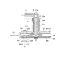
図1は、本発明の実施形態の電子時計の全体構成を示すブロック図、図2は、指針が固定された歯車の部分を示す断面図である。 FIG. 1 is a block diagram showing the overall configuration of an electronic timepiece according to an embodiment of the present invention, and FIG. 2 is a cross-sectional view showing a gear portion to which a pointer is fixed.
この電子時計1は、図1に示すように、時計の全体的な制御を行うCPU(中央演算処理装置)10と、複数の指針2〜5(秒針2、分針3、時針4、機能針5;図2参照)と、各指針2〜5を駆動するためのムーブメント30と、秒針2と分針3の位置検出を行うための第1検出部31と、時針4の位置検出を行うための第2検出部32と、機能針5の位置検出を行うための第3検出部33と、CPU10に作業用のメモリ領域を提供するRAM(Random Access Memory)37と、CPU10が実行する制御プログラムや制御データが格納されたROM(Read Only Memory)36と、制御データが格納されるEEPROM(電気的消去型Programmable ROM)35と、各部に動作電圧を供給する電源部40と、時刻修正用に標準電波を受信するアンテナ41および検波回路42と、CPU10に所定周波数の信号を供給するための発振回路38および分周回路39と、暗闇でアナログ表示部を照らすための照明部43および照明駆動回路44と、アラーム出力を行うスピーカー45およびブザー回路46と、複数の操作ボタンを有し外部から操作指令を入力する操作部47等を備えている。
As shown in FIG. 1, the electronic timepiece 1 includes a CPU (central processing unit) 10 that performs overall control of the timepiece, and a plurality of
ムーブメント30には、秒針2を駆動する第1モータ51と、分針3を駆動する第2モータ52と、時針4を駆動する第3モータ53と、機能針5を駆動する第4モータ54とが設けられている。これら第1〜第4モータ51〜54はそれぞれ2極のステータと2極のロータとを有するステッピングモータであり、出力する駆動パルスの波形を変化させることで正転と逆転との駆動が可能にされている。
The
また、ムーブメント30には、第1〜第4モータ51〜54の回転運動を各指針2〜5まで伝達する輪列機構20が設けられている。この輪列機構20には、図2に示すように、複数の指針歯車として、秒針軸24aを介して秒針2が固着される秒針車24と、分針軸25aを介して分針3が固着される分針車25と、時針軸27aを介して時針4が固着される時針車27と、機能針軸28aを介して機能針5が固着される機能針車28とが含まれる。秒針車24、分針車25、時針車27および機能針車28は、それぞれ同一の回転軸を中心に、第1〜第4モータ51〜54の駆動力によって、それぞれ独立的に回転駆動可能になっている。
Further, the
特に制限されるものではないが、この実施形態では、秒針2および秒針車24は第1モータ51の60ステップの回転により一周し、分針3および分針車25は第2モータ52の360ステップの回転により一周し、時針4および時針車27は第3モータ53の360ステップの回転により一周し、機能針5および機能針車28は第4モータ54の360ステップの回転により一周するように輪列機構20が設計されている。
Although not particularly limited, in this embodiment, the
第1検出部31は、図2にも示すように、秒針車24、分針車25、中間車26、時針車27および機能針車28を間に挟んで、一方から検出位置Pに光を照射する発光部311と、他方で検出位置Pを透過してきた光を受光する光センサ312とから構成される。発光部311は、例えば発光ダイオードにより構成され、光センサ312は、例えばフォトトランジスタなどにより構成される。これら発光部311と光センサ312は、予め設定された検出位置Pで、互いに対向した状態に、電子時計1のハウジングの枠部に固定されている。
As shown in FIG. 2, the
第2検出部32は、時針4と連動して回転する検出車217(図5参照)の透過穴217hを検出して時針4の位置を検出するものであり、第1検出部31と同様に発光部と光センサとから構成され、第2の検出位置P2(図5参照)で互いに対向した状態に設けられている。
The
第3検出部33は、機能針5と連動して回転する検出車222(図6参照)の透過穴222hを検出して機能針5の位置を検出するものであり、第1検出部31と同様に発光部と光センサとから構成され、第3の検出位置P3(図6参照)で互いに対向した状態に設けられている。
The third detection unit 33 detects the position of the
ROM36には、分周回路39から送られる信号をカウントしながら適宜なタイミングで第1〜第4モータ51〜54をそれぞれ駆動することで、指針2〜4を運針させて時刻を表示する時刻表示処理のプログラムや、また、指針2〜5を様々に動かして時刻以外の種々の情報を表示させる付加機能処理のプログラムが格納されている。また、所定時間に各指針2〜5に位置ズレが生じていないか確認して位置ズレがあれば修正する針位置検出処理のプログラムが格納されている。さらに、時針4のバックラッシュ量を計測してそのデータをEEPROM35に記憶させるバックラッシュ量設定処理のプログラム36aや、機能針5のバックラッシュ量を計測してそのデータをEEPROM35に記憶させる機能針5のバックラッシュ量設定処理のプログラムが格納されている。
The
EEPROM35には、バックラッシュ量記憶手段として、時針4や機能針5のバックラッシュ量を表わすバックラッシュ量データが設定される記憶領域35aが設けられている。時針4のバックラッシュ量とは、第3モータ53を正転させて時針4を時計回りに回転させた後、第3モータ53を逆転させた場合に、輪列機構20の各歯車間の遊びによって第3モータ53の運動が時針4まで伝達されずに時針4が停止したままとなる第3モータ53の駆動ステップ数を表わすものである。機能針5のバックラッシュ量も同様のものである。
The
図3〜図6には、各指針2〜5を回転する輪列機構を表わした正面図をそれぞれ示す。これらの図において各歯車に形成されている歯は省略している。
3 to 6 are front views showing a gear train mechanism for rotating the
秒針車24は、図3に示すように、五番車211を介して第1モータ51のロータ51aと連結されている。秒針車24には、検出位置Pと重なる半径位置に複数の透過穴(被検出部)24h1〜24h7が形成され、秒針2が0秒位置にあるときに、透過穴24h1が検出位置Pに重なるように組み付けられている。
As shown in FIG. 3, the
分針車25は、図4に示すように、中間車26と二番車212とを介して第2モータ52のロータ52aに連結されている。ロータ52aが1ステップ(180°)回転するごとに、中間車26が30°ずつ、分針車25が1°ずつ回転するようになっている。分針車25には、検出位置Pと重なる半径位置に透過穴(被検出部)25hが形成され、中間車26には、検出位置Pと重なる半径位置に透過穴(被検出部)26hが形成されている。そして、分針3が55分の位置にあるときに、透過穴25h,26hが検出位置Pに重なるように組み付けられている。
As shown in FIG. 4, the
時針車27は、図5に示すように、3個の中間車213,215,216と三番車214とを介して第3モータ53のロータ53aに連結されている。時針車27には、検出位置Pと重なる半径位置に12個の透過穴(被検出部)27hが形成されている。そして、時針4が文字板上の毎時50分〜10分程度の位置にあるときに、何れか1個の透過穴27hが検出位置Pに重なるように組み付けられている。
As shown in FIG. 5, the
さらに、時針4の輪列機構には、時針4の位置を検出するための検出車217が連結されており、この検出車217と中間車213および三番車214にそれぞれ透過穴217h,213h,214hが形成されている。これら3つの透過穴217h,213h,214hは、時針検出用の規定時刻(例えば11時55分、23時55分)に第2の検出位置P2で重なるように設定されている。
Further, a
機能針車28は、図6に示すように、3個の中間車218,220,221と四番車219とを介して第4モータ54のロータ54aに連結されている。機能針車28には、検出位置Pと重なる半径位置に12個の透過穴(被検出部)28hが形成されている。そして、機能針5が文字板上の00秒、05秒、10秒、15秒、20秒、25秒、30秒、35秒、40秒、45秒、50秒、55秒の位置から±2秒程度の範囲にあるときに、何れか1個の透過穴28hが検出位置Pに重なるように組み付けられている。
As shown in FIG. 6, the
さらに、機能針5の輪列機構には、機能針5の位置を検出するための検出車222が連結されており、この検出車222と中間車218および四番車219にそれぞれ透過穴222h,218h,219hが形成されている。これら3つの透過穴222h,218h,219hは、機能針5が検出用の位置(例えば00秒位置)に来たときに第3検出位置P3で重なるように設定されている。
Further, a
次に、上記のように構成された電子時計1の動作について説明する。 Next, the operation of the electronic timepiece 1 configured as described above will be described.
[時刻表示&針位置検出処理]
時刻表示モードの際、CPU10は、分周回路39から入力される所定周期の信号に基づいて、1秒間隔で第1モータ51を1ステップ駆動し、10秒間隔で第2モータ52を1ステップ駆動し、2分間隔で第3モータ53を1ステップ駆動する。これらの制御によって、各指針2〜4により時刻の表示が行われる。
[Time display & Hand position detection processing]
In the time display mode, the
さらに、CPU10は、上記の運針処理と並行して、分周回路39からの所定周期の信号をカウントして現在時刻の計時を行い、また、前記第1〜第4モータ51〜54を1ステップ駆動させるごとに、指針2〜5がどの位置に運針されたか針位置の計数を行う。
Further, in parallel with the above-described hand movement processing, the
そして、図2に示すように、複数の歯車(24〜28)の各透過穴27h,25h,26h,24h1,28hが検出位置Pで重なると想定される計数タイミングで、第1検出部31の発光部311を発光させて光センサ312のセンサ出力を確認する。そして、透過光の受光の有無を判別し、有れば分針3は正常な位置にあり位置ズレは無いと判断する。続いて、第1モータ51が8ステップ駆動される間を通して2ステップの駆動ごとに第1検出部31に検出動作を行わせて、秒針車24の透過穴24h1,24h2が検出位置Pを通過する際の検出パターンが得られたか判別する。そして、この検出パターンが得られていれば、秒針2は正常な位置にあり位置ズレは無いと判断する。
Then, as shown in FIG. 2, at the counting timing at which the transmission holes 27 h, 25 h, 26 h, 24
さらに、図5に示したように、3つの歯車(213,214,217)の透過穴213h,214h,217hが第2検出位置P2で重なると想定される計数タイミングで、CPU10は第2検出部32に検出動作を行わせる。そして、透過穴213h,214h,217hの重なりが検出されれば、時針4は正常な位置にあり位置ズレは無いと判断する。
Further, as shown in FIG. 5, the
同様に、図6に示したように、3つの歯車(218,219,222)の透過穴218h,219h,222hが第3検出位置P3で重なると想定される計数タイミングで、CPU10は第3検出部33に検出動作を行わせる。そして、透過穴218h,219h,222hの重なりが検出されれば、機能針5は正常な位置にあり位置ズレは無いと判断する。
Similarly, as shown in FIG. 6, the
[バックラッシュ量設定処理]
図5と図6に示すように、時針4と機能針5の輪列機構には多くの歯車が介在しているので時針4と機能針5のバックラッシュ量は比較的に大きくなる。時針4のバックラッシュ量や機能針5のバックラッシュ量は、電子時計1の型が同じでも個体ごとにバラツキが生じる。従って、この実施形態の電子時計1では、次のバックラッシュ量設定処理によって、これらのバックラッシュ量を計測して、そのデータをEEPROM35の記憶領域35aに設定する。
[Backlash amount setting processing]
As shown in FIGS. 5 and 6, since many gears are interposed in the train wheel mechanism of the
バックラッシュ量のデータは、付加機能処理で時針4や機能針5を回転方向を逆転させて移動させる際に、第3モータ53や第4モータ54の駆動ステップ数を決定するのに使用される。すなわち、回転方向を逆転させて時針4や機能針5を移動させる際に、時針4や機能針5の移動ステップ数にバックラッシュ量のステップ数を加算して、第3モータ53や第4モータ54を駆動する。このような制御により、歯車の連結部にある遊びを詰めた上で時針4や機能針5を所望の位置まで移動させることができる。
The backlash amount data is used to determine the number of driving steps of the
このバックラッシュ量設定処理は、例えば、工場出荷前の設定工程、或いは、電子時計1をリセットする際などに、操作部47を介して所定の操作がなされることで開始される。なお、このバックラッシュ量設定処理は、複数の指針2〜5が針位置検出用の規定位置まで移動した後に開始される。この規定位置とは、複数の歯車(24〜28)の各透過穴27h,25h,26h,24h1,28hが検出位置Pで重なる位置である。
This backlash amount setting process is started when a predetermined operation is performed via the
図7には、CPU10により実行されるバックラッシュ量設定処理のフローチャートを、図8には、バックラッシュ量設定処理中の指針2〜5の動きを説明する図を示す。
FIG. 7 is a flowchart of the backlash amount setting process executed by the
バックラッシュ量設定処理が開始されると、先ず、CPU10は第3モータ53を1ステップ正転させて時針4を時計回りに1ステップ回転させる(ステップS1)。1ステップ回転させたら、CPU10は第1検出部31に検出動作を行わせ(ステップS2)、光センサ312のセンサ出力に基づいて検出位置Pに透過穴の重なりが有るか無いか判別する(ステップS3)。そして、透過穴の重なりが検出されればステップS1に戻る。
When the backlash amount setting process is started, first, the
バックラッシュ量設定処理の開始時点では、図8(a)に示すように、秒針2と機能針5が00秒位置、分針3が55分位置、時針4が11時55分位置にあり、透過穴27h,25h,26h,24h1,28hが検出位置Pに重なった状態にある。従って、この開始時点から暫くの期間は、ステップS3の判別処理で透過穴の重なりが有りと判別されて、ステップS1〜S3のループ処理が繰り返される。そして、このステップS1〜S3のループ処理が何度も繰り返されていくことで、時針4が時計回りに移動して、時針車27の透過穴27hが検出位置Pから少しずつ外れていく。
At the start of the backlash amount setting process, as shown in FIG. 8A, the
そして、ステップS1〜S3のループ処理がさらに繰り返されると、図8(b)に示すように、時針4が例えば12時10分位置を少し過ぎて、時針車27の透過穴27hが検出位置Pから外れる。すると、ステップS2の検出動作で光センサ312に届く光が減って、ステップS3の判別処理で透過穴の重なりが無いと判別される。そして、ステップS1〜S3のループ処理を抜けて、次に移行する。
Then, when the loop processing of steps S1 to S3 is further repeated, as shown in FIG. 8B, the
次に移行すると、CPU10は、第3モータ53を1ステップ逆転させて(ステップS4)、RAM37中に設けた変数の時針逆転カウント値を「+1」加算する(ステップS5)。この時針逆転カウント値の初期値は「0」である。そして、第1検出部31に検出動作を行わせ(ステップS6)、光センサ312のセンサ出力に基づいて検出位置Pに透過穴の重なりが有るか無いか判別する(ステップS7)。そして、透過穴の重なりが無いと判別されればステップS4に戻る。
Next, the
時針4を時計回りに回転させた後に、第3モータ53を逆転させても、第3モータ53の回転運動は輪列機構20のバックラッシュによりすぐに時針車27まで伝達されない。従って、輪列機構20のバックラッシュが逆転側に詰って時針車27に運動が伝達されるようになるまでは、ステップS7で透過穴の重なりが無いという判別結果が続き、ステップS4〜S7のループ処理が繰り返される。
Even if the
そして、このステップS4〜S7のループ処理が繰り返される間に、このループ処理の繰り返し回数、すなわち、時針4が時計回りに回転した後、第3モータ53の逆転により輪列機構20のバックラッシュが逆転側に詰って時針4が反時計回りに回転を開始するまでの第3モータ53のステップ数が、RAM37中の変数(時針逆転カウント値)にカウントされることになる。
Then, while the loop processing of steps S4 to S7 is repeated, the number of times this loop processing is repeated, that is, after the
そして、図8(b)→(c)に示すように、輪列機構20のバックラッシュが逆回転側に詰って時針4が反時計回りに1ステップ移動すると、ステップS7の判別で透過穴の重なり有りと判別されて、ステップS4〜S7のループ処理を抜ける。
Then, as shown in FIGS. 8B to 8C, when the backlash of the
ループ処理を抜けたら、CPU10は、上記の時針逆転カウント値に基づいて第3モータ53から時針4までのバックラッシュ量を計算する(ステップS8)。すなわち、バックラッシュ量の定義を、時針4を時計回りに移動させた後、第3モータ53を逆転させて時針4が反時計回りに移動を開始する直前までの第3モータ53の駆動ステップ数とすれば、上記の時針逆転カウント値から「1」を減算して、バックラッシュ量を求める。上記ステップS1〜S8の処理によりバックラッシュ量計測制御手段が構成される。
After exiting the loop processing, the
そして、このバックラッシュ量のデータをEEPROM35の記憶領域35aに時針4についてのバックラッシュ量データとして記憶させる(ステップS9:バックラッシュ量記憶ステップ)。そして、このバックラッシュ量設定処理を終了する。
Then, the backlash amount data is stored in the
時針4についてのバックラッシュ量設定処理が終了したら、続いて、CPU10は、機能針5についてのバックラッシュ量設定処理を開始する。処理の開始時には、時針車27の透過穴27hが検出位置Pに中央で重なる位置まで戻され、その後、第3モータ53の代わりに第4モータ54を駆動して機能針5のバックラッシュ量をカウントし、そのデータをEEPPOM35の記憶領域35aに記憶する。この機能針5のバックラッシュ量設定処理は、図7の時針4のバックラッシュ量設定処理とほぼ同様なので詳細な説明は省略する。
When the backlash amount setting process for the
以上のように、この実施形態の電子時計1によれば、第1検出部31に検出動作を行わせながら第3モータ53を正転と逆転とに回転させることで時針4のバックラッシュ量を計測し、このバックラッシュ量のデータを記憶領域35aに記憶させるようになっている。同様に、機能針5のバックラッシュ量を計測してそのデータを記憶領域35aに記憶させるようになっている。従って、時針4や機能針5を所望の位置まで反時計回りに移動させるような制御を行う場合に、上記のバックラッシュ量データに基づき第3モータ53や第4モータ54を余計に逆転させるステップ数を取得することができる。
As described above, according to the electronic timepiece 1 of this embodiment, the backlash amount of the
また、この実施形態の電子時計1によれば、他の歯車が検出位置Pを塞いでいない状態で、第3モータ53を正転させて検出結果が透過穴の重なり有りから無しへ変化した後、第3モータ53を逆転させて検出結果が透過穴の重なり無しから有りへ変化するまで、第3モータ53の駆動ステップ数を計数し、この計数値から時針4のバックラッシュ量を算出するようになっている。従って、容易に且つ確実に時針4のバックラッシュ量を計測することが可能になっている。
Further, according to the electronic timepiece 1 of this embodiment, after the
また、この実施形態の電子時計1によれば、第1検出部31や各歯車の透過穴は、針位置検出に使用するために設けられており、これらを流用してバックラッシュ量を計測しているので、バックラッシュ量の計測のために部品数が増すこともない。
Further, according to the electronic timepiece 1 of this embodiment, the
また、第1検出部31は、歯車の一面側から検出位置に光を照射し、他面側で透過穴を透過した光を検出位置で受光することで、歯車の透過穴が検出位置に重なっているか否かを判別する構成なので、歯車位置を確実に検出できるようになっている。
Further, the
なお、本発明は、上記実施の形態に限られるものではなく、様々な変更が可能である。例えば、上記実施形態では、バックラッシュ量を計測する指針として、文字板の中央で回転する時針4や機能針5を例示したが、文字板の一部に設けられた小窓内で回転する小針を対象とすることもできる。
The present invention is not limited to the above-described embodiment, and various modifications can be made. For example, in the above-described embodiment, the
また、バックラッシュ量を計数する方法も、例えば、第1検出部31の検出により透過穴の重なりが無しと判別された後、さらに第3モータ53を余計に所定ステップ正転させ、その後に、時針逆転カウントを行いながら第3モータ53を逆転させて時針4のバックラッシュ量を計数するようにしても良い。このように、第3モータ53を逆転させる前に、時針4を余計に進めておくことで、時針車27の透過穴27hが透過穴の有無を判別するしきい値ぎりぎりのところで停止した状態で、時針逆転カウントが行われて、時針車27が動いてないのに何らかの揺らぎにより透過穴が有りと判別されて、誤ったバックラッシュ量が設定されてしまうことを回避できる。
Also, the method for counting the amount of backlash is, for example, after the detection of the
また、上記実施形態では、光の照射により検出可能な被検出部として光を透過する透過穴を適用した例を示したが、被検出部を反射面により構成し、反射した光を受光することで被検出部を検出するようにしても良い。その他、実施形態で示した細部等は、発明の趣旨を逸脱しない範囲で適宜変更可能である。 In the above-described embodiment, an example in which a transmission hole that transmits light is applied as a detected portion that can be detected by light irradiation. However, the detected portion is configured by a reflective surface and receives reflected light. The detected part may be detected by the above. In addition, the details shown in the embodiments can be appropriately changed without departing from the spirit of the invention.
1 電子時計
2 秒針
3 分針
4 時針(第1指針)
5 機能針
10 CPU
20 輪列機構
27 時針車(第1指針歯車)
27h 透過穴
28 機能針車
28h 透過穴
31 第1検出部(検出手段、針位置検出手段)
311 発光部
312 光センサ
35 EEPROM
35a バックラッシュ量データの記憶領域
36 ROM
36a バックラッシュ量設定処理プログラム
37 RAM
53 第3モータ(第1ステッピングモータ)
54 第4モータ
P 検出位置
1
5
20
311
35a Storage area for
36a Backlash amount setting
53 Third motor (first stepping motor)
54 Fourth motor P detection position
Claims (4)
前記第1指針を駆動する第1ステッピングモータと、
複数の歯車が連結されてなり前記第1ステッピングモータの回転運動を前記第1指針に伝達する第1輪列機構と、
前記第1輪列機構の歯車のうち前記第1指針が固定される第1指針歯車と、
前記第1指針歯車に設けられ光の照射により検出可能な第1被検出部と、
前記第1指針歯車の前記第1被検出部が通過する検出位置に光を照射して前記第1被検出部の有無を検出する検出手段と、
前記第1指針以外の指針が固定される第2指針歯車と、
前記第2指針歯車に設けられ前記検出手段による光の照射により検出可能な第2被検出部と、
前記検出手段に検出動作を行わせながら前記第1ステッピングモータを正転と逆転とに回転させることで、前記第1輪列機構における前記第1ステッピングモータから前記第1指針歯車までの遊び量を計測するバックラッシュ量計測制御手段と、
前記バックラッシュ量計測制御手段により計測された前記遊び量のデータを記憶するバックラッシュ量記憶手段と、
を備え、
前記バックラッシュ量計測制御手段は、
前記第1指針歯車に設けられた第1被検出部と前記第2指針歯車に設けられた第2被検出部が前記検出位置に重なった状態から前記検出手段に検出動作を行わせながら前記第1ステッピングモータを正転に回転させて前記第1被検出部の検出結果の変化を判別した後、前記検出手段の検出動作を行わせながら前記第1ステッピングモータを逆転に回転させて前記第1被検出部の検出結果の逆の変化を判別するまで、前記第1ステッピングモータの回転量を計数し、この計数の結果に基づいて前記第1ステッピングモータから前記第1指針歯車までの前記第1輪列機構の遊び量を算出することを特徴とする電子時計。 The first guideline,
A first stepping motor for driving the first pointer;
A first gear train mechanism in which a plurality of gears are connected to transmit the rotational motion of the first stepping motor to the first pointer;
A first pointer gear to which the first pointer is fixed among the gears of the first gear train mechanism;
A first detected portion provided on the first pointer gear and detectable by light irradiation;
Detecting means for detecting the presence or absence of the first detected portion by irradiating light to a detection position through which the first detected portion of the first pointer gear passes ;
A second pointer gear to which a pointer other than the first pointer is fixed;
A second detected portion provided on the second pointer gear and capable of being detected by light irradiation by the detecting means;
The play amount from the first stepping motor to the first pointer gear in the first gear train mechanism is rotated by rotating the first stepping motor forward and reverse while causing the detection means to perform a detection operation. Backlash amount measurement control means for measuring,
Backlash amount storage means for storing the play amount data measured by the backlash amount measurement control means;
Equipped with a,
The backlash amount measurement control means includes
The first detecting portion provided on the first pointer gear and the second detected portion provided on the second pointer gear are overlapped with the detection position, and the detection means performs the detection operation while performing the detection operation. The first stepping motor is rotated in the forward direction to determine the change in the detection result of the first detected portion, and then the first stepping motor is rotated in the reverse direction while performing the detection operation of the detecting means. The rotation amount of the first stepping motor is counted until a reverse change in the detection result of the detected portion is determined, and the first stepping motor to the first pointer gear is counted based on the counting result. An electronic timepiece characterized by calculating a play amount of a train wheel mechanism .
前記第1指針歯車を含むとともに前記複数の指針がそれぞれ固定される複数の指針歯車と、
を備え、
前記複数の指針歯車の前記検出位置と重なる半径位置にそれぞれ設けられ光の照射により検出可能な複数の被検出部と、
前記複数の指針のうち1つ又は複数の指針の位置を検出するために、前記検出位置に光を照射して前記複数の指針歯車の各被検出部が前記検出位置で重なった状態を検出する針位置検出手段と、
を備え、
前記遊び量を計測するための前記検出手段が前記針位置検出手段と兼用されていることを特徴とする請求項1記載の電子時計。 A plurality of pointers including the first pointer;
A plurality of pointer gears including the first pointer gear and to which the plurality of pointers are respectively fixed;
With
A plurality of detected portions that are respectively provided at radial positions overlapping the detection positions of the plurality of pointer gears and can be detected by light irradiation;
In order to detect the position of one or a plurality of hands among the plurality of hands, the detection position is irradiated with light to detect a state in which each detected portion of the plurality of pointer gears is overlapped at the detection position. Needle position detecting means;
With
Electronic timepiece according to claim 1, characterized in that said detecting means for measuring the amount of play is also used as the hand position detection means.
前記検出手段は、前記第1指針歯車の一面側から前記検出位置に光を照射する発光部と、前記第1指針歯車の他面側で前記検出位置を透過した光を検出する光センサとから構成されることを特徴とする請求項1又は2記載の電子時計。 The first detected part is a transmission hole that transmits light;
The detection means includes: a light emitting unit that irradiates light to the detection position from one surface side of the first pointer gear; and an optical sensor that detects light transmitted through the detection position on the other surface side of the first pointer gear. 3. The electronic timepiece according to claim 1 , wherein the electronic timepiece is configured.
前記検出手段に検出動作を行わせながら前記第1ステッピングモータを正転と逆転とに回転させることで、前記第1輪列機構における前記第1ステッピングモータから前記第1指針歯車までの遊び量を計測するバックラッシュ量計測制御ステップと、
前記バックラッシュ量計測制御ステップにより計測された前記遊び量を表わす遊び量データを記憶手段に記憶させるバックラッシュ量記憶ステップと、を含み、
前記バックラッシュ量計測制御ステップは、
前記第1指針歯車に設けられた第1被検出部と前記第2指針歯車に設けられた第2被検出部が前記検出位置に重なった状態から前記検出手段に検出動作を行わせながら前記第1ステッピングモータを正転に回転させて前記第1被検出部の検出結果の変化を判別した後、前記検出手段の検出動作を行わせながら前記第1ステッピングモータを逆転に回転させて前記第1被検出部の検出結果の逆の変化を判別するまで、前記第1ステッピングモータの回転量を計数し、この計数の結果に基づいて前記第1ステッピングモータから前記第1指針歯車までの前記第1輪列機構の遊び量を算出することを特徴とするバックラッシュ量設定方法。 A first wheel train mechanism that transmits a rotational motion of the first stepping motor to the first pointer, the first stepping motor that drives the first pointer, a plurality of gears connected to the first pointer; Of the gears of the first gear train mechanism, a first pointer gear to which the first pointer is fixed, a first detected portion provided on the first pointer gear and detectable by light irradiation, and the first pointer gear Detecting means for detecting the presence or absence of the first detected portion by irradiating light to a detection position through which the first detected portion passes, a second pointer gear to which a pointer other than the first pointer is fixed, A back for setting play amount data representing a play amount of the first gear train mechanism in an electronic timepiece provided with a second detected portion provided on the second pointer gear and detectable by light irradiation by the detecting means. A rush amount setting method,
The play amount from the first stepping motor to the first pointer gear in the first gear train mechanism is rotated by rotating the first stepping motor forward and reverse while causing the detection means to perform a detection operation. Backlash amount measurement control step to measure,
A backlash amount storage step for storing play amount data representing the play amount measured by the backlash amount measurement control step in a storage means ,
The backlash amount measurement control step includes:
The first detecting portion provided on the first pointer gear and the second detected portion provided on the second pointer gear are overlapped with the detection position, and the detection means performs the detection operation while performing the detection operation. The first stepping motor is rotated in the forward direction to determine the change in the detection result of the first detected portion, and then the first stepping motor is rotated in the reverse direction while performing the detection operation of the detecting means. The rotation amount of the first stepping motor is counted until a reverse change in the detection result of the detected portion is determined, and the first stepping motor to the first pointer gear is counted based on the counting result. A backlash amount setting method characterized by calculating a play amount of a train wheel mechanism .
Priority Applications (1)
| Application Number | Priority Date | Filing Date | Title |
|---|---|---|---|
| JP2010235073A JP5671935B2 (en) | 2010-10-20 | 2010-10-20 | Electronic clock and backlash amount setting method |
Applications Claiming Priority (1)
| Application Number | Priority Date | Filing Date | Title |
|---|---|---|---|
| JP2010235073A JP5671935B2 (en) | 2010-10-20 | 2010-10-20 | Electronic clock and backlash amount setting method |
Publications (3)
| Publication Number | Publication Date |
|---|---|
| JP2012088175A JP2012088175A (en) | 2012-05-10 |
| JP2012088175A5 JP2012088175A5 (en) | 2013-11-28 |
| JP5671935B2 true JP5671935B2 (en) | 2015-02-18 |
Family
ID=46259947
Family Applications (1)
| Application Number | Title | Priority Date | Filing Date |
|---|---|---|---|
| JP2010235073A Active JP5671935B2 (en) | 2010-10-20 | 2010-10-20 | Electronic clock and backlash amount setting method |
Country Status (1)
| Country | Link |
|---|---|
| JP (1) | JP5671935B2 (en) |
Family Cites Families (3)
| Publication number | Priority date | Publication date | Assignee | Title |
|---|---|---|---|---|
| JPS5582985A (en) * | 1978-12-19 | 1980-06-23 | Citizen Watch Co Ltd | Pointer indication type electronic watch |
| JP3185711B2 (en) * | 1997-05-20 | 2001-07-11 | 日本ビクター株式会社 | Magnetic recording / reproducing device |
| JP2004276396A (en) * | 2003-03-14 | 2004-10-07 | Seiko Epson Corp | Method for calculating positional shift correction amount of heading and printer |
-
2010
- 2010-10-20 JP JP2010235073A patent/JP5671935B2/en active Active
Also Published As
| Publication number | Publication date |
|---|---|
| JP2012088175A (en) | 2012-05-10 |
Similar Documents
| Publication | Publication Date | Title |
|---|---|---|
| JP4623140B2 (en) | Needle position detection device and needle position detection control method | |
| EP2333622B1 (en) | Hand position detecting device and electronic timepiece | |
| US20170075306A1 (en) | Analog electronic watch | |
| US8929179B2 (en) | Analog electronic timepiece having rotating display bodies and a detection unit detecting when a rotating display body is in a predetermined reference display mode | |
| JP3514644B2 (en) | Auto correct clock | |
| JP4475311B2 (en) | Penetration state discrimination device and electronic timepiece | |
| JP5521952B2 (en) | Information display device | |
| JP5671935B2 (en) | Electronic clock and backlash amount setting method | |
| JP2011191220A (en) | Analog electronic timepiece | |
| JPH0593784A (en) | Analog timepiece device | |
| JP2009156787A (en) | Device for discriminating penetration state, and electronic timepiece | |
| US8213268B2 (en) | Chronograph timepiece | |
| JP6094063B2 (en) | Analog electronic clock | |
| JP5190702B2 (en) | Needle position processing controller | |
| JP2002071846A (en) | Automatic correction clock | |
| JP2010112860A (en) | Electronic compass | |
| JP6327013B2 (en) | Electronic clock hand position detection method and electronic clock | |
| JP2010204066A (en) | Pointer drive control device and analog electronic timepiece | |
| JP5353518B2 (en) | Electronic clock | |
| JP4993006B2 (en) | Needle position detection device and needle position detection method | |
| JP2011127907A (en) | Analog electronic timepiece | |
| JP4878275B2 (en) | Analog radio clock | |
| JP5790823B2 (en) | Information display device | |
| JP5182348B2 (en) | Needle position detection device and needle position detection control method | |
| JP5194871B2 (en) | Member position detecting device and electronic timepiece |
Legal Events
| Date | Code | Title | Description |
|---|---|---|---|
| A521 | Written amendment |
Free format text: JAPANESE INTERMEDIATE CODE: A523 Effective date: 20131011 |
|
| A621 | Written request for application examination |
Free format text: JAPANESE INTERMEDIATE CODE: A621 Effective date: 20131011 |
|
| A977 | Report on retrieval |
Free format text: JAPANESE INTERMEDIATE CODE: A971007 Effective date: 20140528 |
|
| A131 | Notification of reasons for refusal |
Free format text: JAPANESE INTERMEDIATE CODE: A131 Effective date: 20140603 |
|
| A521 | Written amendment |
Free format text: JAPANESE INTERMEDIATE CODE: A523 Effective date: 20140801 |
|
| TRDD | Decision of grant or rejection written | ||
| A01 | Written decision to grant a patent or to grant a registration (utility model) |
Free format text: JAPANESE INTERMEDIATE CODE: A01 Effective date: 20141125 |
|
| A61 | First payment of annual fees (during grant procedure) |
Free format text: JAPANESE INTERMEDIATE CODE: A61 Effective date: 20141208 |
|
| R150 | Certificate of patent (=grant) or registration of utility model |
Ref document number: 5671935 Country of ref document: JP Free format text: JAPANESE INTERMEDIATE CODE: R150 |