JP5670403B2 - Motor drive control device and electric assist vehicle - Google Patents
Motor drive control device and electric assist vehicle Download PDFInfo
- Publication number
- JP5670403B2 JP5670403B2 JP2012237964A JP2012237964A JP5670403B2 JP 5670403 B2 JP5670403 B2 JP 5670403B2 JP 2012237964 A JP2012237964 A JP 2012237964A JP 2012237964 A JP2012237964 A JP 2012237964A JP 5670403 B2 JP5670403 B2 JP 5670403B2
- Authority
- JP
- Japan
- Prior art keywords
- control
- vehicle speed
- regenerative
- value
- control coefficient
- Prior art date
- Legal status (The legal status is an assumption and is not a legal conclusion. Google has not performed a legal analysis and makes no representation as to the accuracy of the status listed.)
- Active
Links
- 230000001172 regenerating effect Effects 0.000 claims description 99
- 230000008929 regeneration Effects 0.000 claims description 45
- 238000011069 regeneration method Methods 0.000 claims description 45
- 238000001514 detection method Methods 0.000 claims description 25
- 230000007423 decrease Effects 0.000 claims description 11
- 230000003247 decreasing effect Effects 0.000 claims description 4
- 230000007420 reactivation Effects 0.000 claims 1
- 238000000034 method Methods 0.000 description 20
- 238000010586 diagram Methods 0.000 description 19
- 230000001133 acceleration Effects 0.000 description 6
- 235000014676 Phragmites communis Nutrition 0.000 description 4
- 230000006870 function Effects 0.000 description 4
- 230000001629 suppression Effects 0.000 description 3
- HBBGRARXTFLTSG-UHFFFAOYSA-N Lithium ion Chemical compound [Li+] HBBGRARXTFLTSG-UHFFFAOYSA-N 0.000 description 2
- 230000000295 complement effect Effects 0.000 description 2
- 229910001416 lithium ion Inorganic materials 0.000 description 2
- 230000004044 response Effects 0.000 description 2
- PXHVJJICTQNCMI-UHFFFAOYSA-N Nickel Chemical compound [Ni] PXHVJJICTQNCMI-UHFFFAOYSA-N 0.000 description 1
- 238000006243 chemical reaction Methods 0.000 description 1
- 230000000694 effects Effects 0.000 description 1
- 238000005516 engineering process Methods 0.000 description 1
- 230000005669 field effect Effects 0.000 description 1
- 238000005259 measurement Methods 0.000 description 1
- 229910000652 nickel hydride Inorganic materials 0.000 description 1
- 230000003287 optical effect Effects 0.000 description 1
- 229920000642 polymer Polymers 0.000 description 1
- 239000004065 semiconductor Substances 0.000 description 1
Images


Classifications
-
- B—PERFORMING OPERATIONS; TRANSPORTING
- B62—LAND VEHICLES FOR TRAVELLING OTHERWISE THAN ON RAILS
- B62M—RIDER PROPULSION OF WHEELED VEHICLES OR SLEDGES; POWERED PROPULSION OF SLEDGES OR SINGLE-TRACK CYCLES; TRANSMISSIONS SPECIALLY ADAPTED FOR SUCH VEHICLES
- B62M6/00—Rider propulsion of wheeled vehicles with additional source of power, e.g. combustion engine or electric motor
- B62M6/40—Rider propelled cycles with auxiliary electric motor
- B62M6/45—Control or actuating devices therefor
-
- B—PERFORMING OPERATIONS; TRANSPORTING
- B60—VEHICLES IN GENERAL
- B60L—PROPULSION OF ELECTRICALLY-PROPELLED VEHICLES; SUPPLYING ELECTRIC POWER FOR AUXILIARY EQUIPMENT OF ELECTRICALLY-PROPELLED VEHICLES; ELECTRODYNAMIC BRAKE SYSTEMS FOR VEHICLES IN GENERAL; MAGNETIC SUSPENSION OR LEVITATION FOR VEHICLES; MONITORING OPERATING VARIABLES OF ELECTRICALLY-PROPELLED VEHICLES; ELECTRIC SAFETY DEVICES FOR ELECTRICALLY-PROPELLED VEHICLES
- B60L15/00—Methods, circuits, or devices for controlling the traction-motor speed of electrically-propelled vehicles
- B60L15/20—Methods, circuits, or devices for controlling the traction-motor speed of electrically-propelled vehicles for control of the vehicle or its driving motor to achieve a desired performance, e.g. speed, torque, programmed variation of speed
- B60L15/2045—Methods, circuits, or devices for controlling the traction-motor speed of electrically-propelled vehicles for control of the vehicle or its driving motor to achieve a desired performance, e.g. speed, torque, programmed variation of speed for optimising the use of energy
-
- B—PERFORMING OPERATIONS; TRANSPORTING
- B60—VEHICLES IN GENERAL
- B60L—PROPULSION OF ELECTRICALLY-PROPELLED VEHICLES; SUPPLYING ELECTRIC POWER FOR AUXILIARY EQUIPMENT OF ELECTRICALLY-PROPELLED VEHICLES; ELECTRODYNAMIC BRAKE SYSTEMS FOR VEHICLES IN GENERAL; MAGNETIC SUSPENSION OR LEVITATION FOR VEHICLES; MONITORING OPERATING VARIABLES OF ELECTRICALLY-PROPELLED VEHICLES; ELECTRIC SAFETY DEVICES FOR ELECTRICALLY-PROPELLED VEHICLES
- B60L50/00—Electric propulsion with power supplied within the vehicle
- B60L50/20—Electric propulsion with power supplied within the vehicle using propulsion power generated by humans or animals
-
- B—PERFORMING OPERATIONS; TRANSPORTING
- B60—VEHICLES IN GENERAL
- B60L—PROPULSION OF ELECTRICALLY-PROPELLED VEHICLES; SUPPLYING ELECTRIC POWER FOR AUXILIARY EQUIPMENT OF ELECTRICALLY-PROPELLED VEHICLES; ELECTRODYNAMIC BRAKE SYSTEMS FOR VEHICLES IN GENERAL; MAGNETIC SUSPENSION OR LEVITATION FOR VEHICLES; MONITORING OPERATING VARIABLES OF ELECTRICALLY-PROPELLED VEHICLES; ELECTRIC SAFETY DEVICES FOR ELECTRICALLY-PROPELLED VEHICLES
- B60L50/00—Electric propulsion with power supplied within the vehicle
- B60L50/50—Electric propulsion with power supplied within the vehicle using propulsion power supplied by batteries or fuel cells
- B60L50/60—Electric propulsion with power supplied within the vehicle using propulsion power supplied by batteries or fuel cells using power supplied by batteries
- B60L50/66—Arrangements of batteries
-
- B—PERFORMING OPERATIONS; TRANSPORTING
- B60—VEHICLES IN GENERAL
- B60L—PROPULSION OF ELECTRICALLY-PROPELLED VEHICLES; SUPPLYING ELECTRIC POWER FOR AUXILIARY EQUIPMENT OF ELECTRICALLY-PROPELLED VEHICLES; ELECTRODYNAMIC BRAKE SYSTEMS FOR VEHICLES IN GENERAL; MAGNETIC SUSPENSION OR LEVITATION FOR VEHICLES; MONITORING OPERATING VARIABLES OF ELECTRICALLY-PROPELLED VEHICLES; ELECTRIC SAFETY DEVICES FOR ELECTRICALLY-PROPELLED VEHICLES
- B60L2200/00—Type of vehicles
- B60L2200/12—Bikes
-
- B—PERFORMING OPERATIONS; TRANSPORTING
- B60—VEHICLES IN GENERAL
- B60L—PROPULSION OF ELECTRICALLY-PROPELLED VEHICLES; SUPPLYING ELECTRIC POWER FOR AUXILIARY EQUIPMENT OF ELECTRICALLY-PROPELLED VEHICLES; ELECTRODYNAMIC BRAKE SYSTEMS FOR VEHICLES IN GENERAL; MAGNETIC SUSPENSION OR LEVITATION FOR VEHICLES; MONITORING OPERATING VARIABLES OF ELECTRICALLY-PROPELLED VEHICLES; ELECTRIC SAFETY DEVICES FOR ELECTRICALLY-PROPELLED VEHICLES
- B60L2220/00—Electrical machine types; Structures or applications thereof
- B60L2220/40—Electrical machine applications
- B60L2220/44—Wheel Hub motors, i.e. integrated in the wheel hub
-
- Y—GENERAL TAGGING OF NEW TECHNOLOGICAL DEVELOPMENTS; GENERAL TAGGING OF CROSS-SECTIONAL TECHNOLOGIES SPANNING OVER SEVERAL SECTIONS OF THE IPC; TECHNICAL SUBJECTS COVERED BY FORMER USPC CROSS-REFERENCE ART COLLECTIONS [XRACs] AND DIGESTS
- Y02—TECHNOLOGIES OR APPLICATIONS FOR MITIGATION OR ADAPTATION AGAINST CLIMATE CHANGE
- Y02T—CLIMATE CHANGE MITIGATION TECHNOLOGIES RELATED TO TRANSPORTATION
- Y02T10/00—Road transport of goods or passengers
- Y02T10/60—Other road transportation technologies with climate change mitigation effect
- Y02T10/64—Electric machine technologies in electromobility
-
- Y—GENERAL TAGGING OF NEW TECHNOLOGICAL DEVELOPMENTS; GENERAL TAGGING OF CROSS-SECTIONAL TECHNOLOGIES SPANNING OVER SEVERAL SECTIONS OF THE IPC; TECHNICAL SUBJECTS COVERED BY FORMER USPC CROSS-REFERENCE ART COLLECTIONS [XRACs] AND DIGESTS
- Y02—TECHNOLOGIES OR APPLICATIONS FOR MITIGATION OR ADAPTATION AGAINST CLIMATE CHANGE
- Y02T—CLIMATE CHANGE MITIGATION TECHNOLOGIES RELATED TO TRANSPORTATION
- Y02T10/00—Road transport of goods or passengers
- Y02T10/60—Other road transportation technologies with climate change mitigation effect
- Y02T10/70—Energy storage systems for electromobility, e.g. batteries
-
- Y—GENERAL TAGGING OF NEW TECHNOLOGICAL DEVELOPMENTS; GENERAL TAGGING OF CROSS-SECTIONAL TECHNOLOGIES SPANNING OVER SEVERAL SECTIONS OF THE IPC; TECHNICAL SUBJECTS COVERED BY FORMER USPC CROSS-REFERENCE ART COLLECTIONS [XRACs] AND DIGESTS
- Y02—TECHNOLOGIES OR APPLICATIONS FOR MITIGATION OR ADAPTATION AGAINST CLIMATE CHANGE
- Y02T—CLIMATE CHANGE MITIGATION TECHNOLOGIES RELATED TO TRANSPORTATION
- Y02T10/00—Road transport of goods or passengers
- Y02T10/60—Other road transportation technologies with climate change mitigation effect
- Y02T10/72—Electric energy management in electromobility
Landscapes
- Engineering & Computer Science (AREA)
- Transportation (AREA)
- Mechanical Engineering (AREA)
- Power Engineering (AREA)
- Chemical & Material Sciences (AREA)
- Combustion & Propulsion (AREA)
- Life Sciences & Earth Sciences (AREA)
- Sustainable Development (AREA)
- Sustainable Energy (AREA)
- Electric Propulsion And Braking For Vehicles (AREA)
- Control Of Ac Motors In General (AREA)
Description
本発明は、電動アシスト車における回生制御技術に関する。 The present invention relates to a regeneration control technique in an electric assist vehicle.
バッテリの電力を使用してモータを駆動する電動自転車などの電動アシスト車には、ブレーキレバーにセンサを設け、乗員によるブレーキの操作に応じてモータを回生動作させることで車両の運動エネルギーをバッテリに回収し、走行距離を向上させる技術が用いられている物がある。 In an electric assist vehicle such as an electric bicycle that uses the power of the battery to drive the motor, a sensor is provided on the brake lever, and the motor is regenerated according to the brake operation by the occupant, so that the kinetic energy of the vehicle is transferred to the battery. There are things that use techniques to recover and improve mileage.
また、自転車の場合、自動車や自動二輪車と異なりエンジンブレーキがないため、長い下り坂において過度な加速で危険を感じるため、ブレーキ操作で速度を制御することになる。しかしながら、このようなブレーキ操作は、搭乗者にとっては煩わしかったり、継続したブレーキ操作により手が疲れるという問題がある。 In the case of a bicycle, unlike an automobile or a motorcycle, there is no engine brake. Therefore, the speed is controlled by a brake operation because there is a danger of excessive acceleration on a long downhill. However, such a brake operation has a problem that it is troublesome for the passenger, and the hand becomes tired due to the continued brake operation.
さらに、電動自転車などの電動アシスト車には、予めなされている設定に従って自動的に回生制動を行うという技術もあるが、予めなされている設定が搭乗者の意図に沿ったものであるとは限らない。すなわち、長い下り坂で搭乗者が快適と感じる速度は、道幅や天候状況、搭乗者の体調等により変化する。従って、搭乗者によっては、ストレスを感じるような過度な減速が行われたり、逆に減速が足りずに危険を感じたりする場合がある。 In addition, there is a technique in which an electrically assisted vehicle such as an electric bicycle automatically performs regenerative braking according to a preset setting, but the preset setting is not always in line with the passenger's intention. Absent. That is, the speed at which the passenger feels comfortable on a long downhill varies depending on the road width, weather conditions, the physical condition of the passenger, and the like. Therefore, depending on the passenger, there is a case where the vehicle is excessively decelerated so as to feel stress, or conversely, there is a danger that the deceleration is insufficient.
従って、本発明の目的は、一側面によれば、搭乗者の意図を加味して回生制動力が働くようにするための技術を提供することである。 Accordingly, an object of the present invention is to provide a technique for allowing a regenerative braking force to work in consideration of a passenger's intention.
本発明に係るモータ駆動制御装置は、(A)搭乗者による回生制御の開始指示又は停止指示を検出する検出部と、(B)検出部により回生制御の開始指示を検出すると、当該検出時における第1の車速を特定すると共に回生目標量に対する制御係数に所定の値を設定し、検出部により回生制御の停止指示を検出するまで、現在車速が第1の車速より速い場合には制御係数の値を増加させ、現在車速が第1の車速より遅い場合には制御係数の値を減少させる制御係数算出部と、(C)制御係数算出部からの制御係数の値と回生目標量とから、モータの駆動を制御する制御部とを有する。 The motor drive control device according to the present invention detects (A) a detection unit that detects a start or stop instruction for regenerative control by a passenger, and (B) detects a start instruction for regenerative control by the detection unit. When the current vehicle speed is higher than the first vehicle speed until the first vehicle speed is specified and a predetermined value is set to the control coefficient for the regeneration target amount, and the stop instruction of the regeneration control is detected by the detection unit, the control coefficient From the control coefficient calculation unit that increases the value and decreases the value of the control coefficient when the current vehicle speed is slower than the first vehicle speed, and (C) the control coefficient value and the regeneration target amount from the control coefficient calculation unit, And a control unit that controls driving of the motor.
このようにすれば搭乗者の意図を加味して回生制動力が働くようになり、可能な限り第1の車速が維持されるように回生制御が行われるようになる。よって、搭乗者が、自らブレーキ操作を繰り返したり維持したりすることなく、適度に回生制動力が効くようになる。 In this way, the regenerative braking force works in consideration of the passenger's intention, and the regenerative control is performed so that the first vehicle speed is maintained as much as possible. Accordingly, the regenerative braking force is appropriately applied without the passenger repeating and maintaining the brake operation himself.
また、上で述べた制御係数算出部が、検出部により回生制御の停止指示を検出する前に回生制御の開始指示を再度検出すると、当該再度の検出時における第2の車速を特定し、現在車速が第2の車速より速い場合には制御係数の値を増加させ、現在車速が第2の車速より遅い場合には制御係数の値を減少させるようにしても良い。このようにすれば、回生制御の停止指示を行うことなく、状況の変化に応じて搭乗者が簡易に意図の変更を指示できるようになる。 In addition, when the control coefficient calculation unit described above detects the regenerative control start instruction again before detecting the regenerative control stop instruction by the detection unit, the second vehicle speed at the time of the re-detection is specified, When the vehicle speed is faster than the second vehicle speed, the value of the control coefficient may be increased, and when the current vehicle speed is slower than the second vehicle speed, the value of the control coefficient may be decreased. In this way, the passenger can easily instruct change of the intention according to the change of the situation without instructing to stop the regenerative control.
さらに、上で述べた制御係数算出部が、検出部から回生制御の停止指示を検出すると、回生制御を解除するように動作する。即ち、搭乗者の意図に応じて設定変更を行うものである。 Furthermore, when the control coefficient calculation unit described above detects a regenerative control stop instruction from the detection unit, it operates to cancel the regenerative control. That is, the setting is changed according to the passenger's intention.
また、上で述べた回生制御の開始指示が、ペダルの所定位相角以上の逆回転、回生制御の開始指示のための指示スイッチのオン、又はブレーキスイッチが所定時間内に連続してオンになったことにより検出される場合もある。簡易に指示できる手段を採用できる。 In addition, the regenerative control start instruction described above is the reverse rotation of the pedal over a predetermined phase angle, the instruction switch for instructing the start of regenerative control is turned on, or the brake switch is continuously turned on within a predetermined time. May be detected. It is possible to adopt a means that allows simple instructions.
さらに、回生制御の停止指示が、ペダルの所定位相角以上の正回転、トルク入力、回生制御の開始指示のための指示スイッチのオフ、又はブレーキスイッチ(例えば開始指示とは別のブレーキスイッチ)が所定時間内に連続してオンになったことにより検出される場合もある。 Further, when the stop instruction of the regenerative control is a forward rotation of a predetermined phase angle or more of the pedal, torque input, an instruction switch for instructing to start the regenerative control is turned off, or a brake switch (for example, a brake switch different from the start instruction) There may be a case where it is detected when it is continuously turned on within a predetermined time.
また、上で述べた制御係数算出部が、制御係数の値が当該制御係数の下限値に達した後現在車速が第1の車速より速くなれば、回生制御の開始指示を検出せずとも制御係数の値を増加させるようにしても良い。このように自動的に回生制動が再開するので、搭乗者は煩わしい操作を繰り返さずとも良くなる。 In addition, the control coefficient calculation unit described above performs control without detecting regenerative control start instruction if the current vehicle speed becomes faster than the first vehicle speed after the control coefficient value reaches the lower limit value of the control coefficient. The coefficient value may be increased. Since regenerative braking automatically resumes in this way, the passenger does not have to repeat troublesome operations.
なお、上で述べたような処理をマイクロプロセッサに実施させるためのプログラムを作成することができ、当該プログラムは、例えばフレキシブル・ディスク、CD−ROMなどの光ディスク、光磁気ディスク、半導体メモリ(例えばROM)、ハードディスク等のコンピュータ読み取り可能な記憶媒体又は記憶装置に格納される。なお、処理途中のデータについては、RAM(Random Access Memory)等の記憶装置に一時保管される。 It is possible to create a program for causing the microprocessor to perform the processing described above, such as a flexible disk, an optical disk such as a CD-ROM, a magneto-optical disk, a semiconductor memory (for example, a ROM). ), And is stored in a computer-readable storage medium such as a hard disk or a storage device. Note that data being processed is temporarily stored in a storage device such as a RAM (Random Access Memory).
一側面によれば、搭乗者の意図を加味した回生制動力が働くようになる。 According to one aspect, a regenerative braking force that takes into account the intention of the passenger is activated.
図1は、本実施の形態における電動アシスト車であるモータ付き自転車の一例を示す外観図である。このモータ付き自転車1は、モータ駆動装置を搭載している。モータ駆動装置は、二次電池101と、モータ駆動制御器102と、トルクセンサ103と、ブレーキセンサ104a及び104bと、モータ105と、ペダル回転センサ107とを有する。なお、図1には示されていないが、モータ駆動装置は、本実施の形態に係る回生制御を指示するための指示スイッチ106をも有する。
FIG. 1 is an external view showing an example of a motor-equipped bicycle that is an electrically assisted vehicle according to the present embodiment. This motorized
二次電池101は、例えば供給最大電圧(満充電時の電圧)が24Vのリチウムイオン二次電池であるが、他種の電池、例えばリチウムイオンポリマー二次電池、ニッケル水素蓄電池などであっても良い。
The
トルクセンサ103は、クランク軸に取付けられたホイールに設けられており、搭乗者によるペダルの踏力を検出し、この検出結果をモータ駆動制御器102に出力する。ペダル回転センサ107は、トルクセンサ103と同様に、クランク軸に取付けられたホイールに設けられており、回転に応じた信号をモータ駆動制御器102に出力する。なお、ペダル回転センサ107は、回転位相角に加えて、ペダルの正転又は逆転といった回転方向についても検出可能であるものとする。
The
ブレーキセンサ104aは、図2のように、ハンドル部90の左端に設けられたグリップ91aと、ブレーキレバー93aとをある程度握った状態になると、オン状態になって当該オン状態を表す信号をモータ駆動制御器102に伝えるようになっている。また、グリップ91a及びブレーキレバー93aを握る程度に応じてブレーキワイヤ92aが引かれて、例えば後輪が機械的に制動される。
As shown in FIG. 2, when the
ブレーキセンサ104bも、グリップ91bとブレーキレバー93bとをある程度握った状態になると、オン状態になって、当該オン状態を表す信号をモータ駆動制御器102に伝えるようになっている。また、グリップ91b及びブレーキレバー93bを握る程度に応じてブレーキワイヤ92bが引かれて、例えば前輪が機械的に制動される。
The
より詳しくは、ブレーキセンサ104a及び104bは、例えば磁石と周知のリードスイッチとから構成されている。磁石は、ブレーキレバー93a及び93bを固定するとともにブレーキワイヤ92a及び92bが送通される筐体内において、ブレーキレバー93a及び93bに連結されたブレーキワイヤ92a及び92bに固定されている。ブレーキレバー93a及び93bが手で握られたときにリードスイッチをオン状態にするようになっている。また、リードスイッチは筐体内に固定されている。このリードスイッチの信号はモータ駆動制御器102に送られる。なお、ブレーキセンサ104a及び104bの構成は、このような方式に限定されるものではなく、光学的にブレーキ操作を検出する方法、機械的なスイッチによりブレーキ操作を検出する方法、電気抵抗の変動によりブレーキ操作を検出する方法などであってもよい。
More specifically, each of the
また、図2には、例えばグリップ91a付近に、本実施の形態に係る回生制御の開始又は停止を指示するための指示スイッチ106が備えられている。このように、グリップ91a付近に設けることによって、グリップ91aを握ったまま指示スイッチ106をオン又はオフさせることができる。指示スイッチ106による指示信号は、モータ駆動制御器102に伝えられる。なお、指示スイッチ106は、グリップ91b付近に設けるようにしても良い。
In FIG. 2, for example, an
指示スイッチ106は、(1)左右に倒すタイプのスイッチ1つで左はON、右はOFFとするタイプ、(2)2つのスイッチを用意して、1つはON、1つはOFFとするタイプ、(3)1つのスイッチを押す毎にON、OFFを切り替えるタイプなどが利用できる。本実施の形態では、ONを継続して入力できるタイプが相応しい。
The
モータ105は、例えば周知の三相直流ブラシレスモータであり、例えばモータ付き自転車1の前輪に装着されている。モータ105は、前輪を回転させるとともに、前輪の回転に応じてローターが回転するように、ローターが前輪に連結されている。さらに、モータ105はホール素子等の回転センサを備えてローターの回転情報(すなわちホール信号)をモータ駆動制御器102に出力する。
The
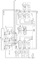
このようなモータ付き自転車1のモータ駆動制御器102に関連する構成を図3に示す。モータ駆動制御器102は、制御器1020と、FET(Field Effect Transistor)ブリッジ1030とを有する。FETブリッジ1030には、モータ105のU相についてのスイッチングを行うハイサイドFET(Suh)及びローサイドFET(Sul)と、モータ105のV相についてのスイッチングを行うハイサイドFET(Svh)及びローサイドFET(Svl)と、モータ105のW相についてのスイッチングを行うハイサイドFET(Swh)及びローサイドFET(Swl)とを含む。このFETブリッジ1030は、コンプリメンタリ型スイッチングアンプの一部を構成している。
A configuration related to the
また、制御器1020は、演算部1021と、指示入力部1022と、ペダル回転入力部1023と、車速入力部1024と、可変遅延回路1025と、モータ駆動タイミング生成部1026と、トルク入力部1027と、ブレーキ入力部1028と、AD入力部1029とを有する。
The
演算部1021は、ペダル回転入力部1023からの入力、指示入力部1022からの入力、車速入力部1024からの入力、トルク入力部1027からの入力、ブレーキ入力部1028からの入力、AD(Analog-Digital)入力部1029からの入力を用いて以下で述べる演算を行って、モータ駆動タイミング生成部1026及び可変遅延回路1025に対して出力を行う。なお、演算部1021は、メモリ10211を有しており、メモリ10211は、演算に用いる各種データ及び処理途中のデータ等を格納する。さらに、演算部1021は、プログラムをプロセッサが実行することによって実現される場合もあり、この場合には当該プログラムがメモリ10211に記録されている場合もある。
The
指示入力部1022は、指示スイッチ106からのオン又はオフを表す信号を演算部1021に出力する。ペダル回転入力部1023は、ペダル回転センサ107からの、ペダル回転位相角及び回転方向を表す信号を、ディジタル化して演算部1021に出力する。車速入力部1024は、モータ105が出力するホール信号から現在車速を算出して、演算部1021に出力する。トルク入力部1027は、トルクセンサ103からの踏力に相当する信号をディジタル化して演算部1021に出力する。ブレーキ入力部1028は、ブレーキセンサ104a及び104bからの信号に応じて、オン信号をいずれのブレーキセンサ104a及び104bからも受信しないブレーキなし状態、ブレーキセンサ104a又は104bからオン信号を受信しているブレーキ状態のいずれかを表す信号を演算部1021に出力する。AD入力部1029は、二次電池101からの出力電圧をディジタル化して演算部1021に出力する。また、メモリ10211は、演算部1021とは別に設けられる場合もある。
The
演算部1021は、演算結果として進角値を可変遅延回路1025に出力する。可変遅延回路1025は、演算部1021から受け取った進角値に基づきホール信号の位相を調整してモータ駆動タイミング生成部1026に出力する。演算部1021は、演算結果として例えばPWM(Pulse Width Modulation)のデューティー比に相当するPWMコードをモータ駆動タイミング生成部1026に出力する。モータ駆動タイミング生成部1026は、可変遅延回路1025からの調整後のホール信号と演算部1021からのPWMコードとに基づいて、FETブリッジ1030に含まれる各FETに対するスイッチング信号を生成して出力する。
The
図4(a)乃至(l)を用いて図3に示した構成によるモータ駆動の基本動作を説明する。図4(a)はモータ105が出力したU相のホール信号HUを表し、図4(b)はモータ105が出力したV相のホール信号HVを表し、図4(c)はモータ105が出力したW相のホール信号HWを表す。このように、ホール信号はモータの回転位相を表している。なお、ここでは回転位相を連続値として得られるわけではないが、他のセンサ等により得られるようにしてもよい。以下でも述べるように、本実施の形態では、モータ105のホール素子を、ホール信号が図4で示すように若干進んだ位相で出力されるよう設置して、可変遅延回路1025で調整可能なようにしている。従って、図4(d)に示すようなU相の調整後ホール信号HU_Inが可変遅延回路1025からモータ駆動タイミング生成部1026に出力され、図4(e)に示すようなV相の調整後ホール信号HV_Inが可変遅延回路1025からモータ駆動タイミング生成部1026に出力され、図4(f)に示すようなW相の調整後ホール信号HW_Inが可変遅延回路1025からモータ駆動タイミング生成部1026に出力される。
The basic operation of the motor drive with the configuration shown in FIG. 3 will be described with reference to FIGS. 4A shows the U-phase hall signal HU output from the
なお、ホール信号1周期を電気角360度として、6つのフェーズに分けられる。 The period of the Hall signal is divided into six phases with an electrical angle of 360 degrees.
また、図4(g)乃至(i)に示すように、U相の端子にMotor_U逆起電力、V相の端子にMotor_V逆起電力、W相の端子にMotor_W逆起電力という逆起電力電圧が発生する。このようなモータ逆起電力電圧に位相を合わせて駆動電圧を与えモータ105を駆動するためには、図4(j)乃至(l)に示すようなスイッチング信号をFETブリッジ1030の各FETのゲートに出力する。図4(j)のU_HSはU相のハイサイドFET(Suh)のゲート信号を表しており、U_LSはU相のローサイドFET(Sul)のゲート信号を表している。PWM及び「/PWM」は、演算部1021の演算結果であるPWMコードに応じたデューティー比でオン/オフする期間を表しており、コンプリメンタリ型であるからPWMがオンであれば/PWMはオフとなり、PWMがオフであれば/PWMはオンとなる。ローサイドFET(Sul)の「On」の区間は、常にオンとなる。図4(k)のV_HSはV相のハイサイドFET(Svh)のゲート信号を表しており、V_LSはV相のローサイドFET(Svl)のゲート信号を表している。記号の意味は図4(j)と同じである。さらに、図4(l)のW_HSはW相のハイサイドFET(Swh)のゲート信号を表しており、W_LSはW相のローサイドFET(Swl)のゲート信号を表している。記号の意味は図4(j)と同じである。
Further, as shown in FIGS. 4G to 4I, a counter electromotive force voltage called a Motor_U back electromotive force at the U phase terminal, a Motor_V back electromotive force at the V phase terminal, and a Motor_W back electromotive force at the W phase terminal. Will occur. In order to drive the
このようにU相のFET(Suh及びSul)は、フェーズ1及び2でPWMのスイッチングを行い、U相のローサイドFET(Sul)は、フェーズ4及び5でオンになる。また、V相のFET(Svh及びSvl)は、フェーズ3及び4でPWMのスイッチングを行い、V相のローサイドFET(Svl)は、フェーズ6及び1でオンになる。さらに、W相のFET(Swh及びSwl)は、フェーズ5及び6でPWMのスイッチングを行い、W相のローサイドFET(Swl)は、フェーズ2及び3でオンになる。
Thus, the U-phase FETs (S uh and S ul ) perform PWM switching in
このような信号を出力してデューティー比を適切に制御すれば、モータ105を所望のトルクで駆動できるようになる。
If such a signal is output and the duty ratio is appropriately controlled, the
次に、演算部1021の機能ブロック図を図5及び図6に示す。まず、図5に、トリガ信号を出力するための機能ブロック図を示す。図5に示すように、イベント検出部1210は、ブレーキ入力部1028と、ペダル回転入力部1023と、指示入力部1022とに接続されている。
Next, functional block diagrams of the
本実施の形態では、(A)指示スイッチ106から当該指示スイッチ106がオンされたことを表す信号を指示入力部1022が検出して、当該信号をイベント検出部1210に出力した場合、イベント検出部1210は、この信号に応じて回生制御の開始を表すトリガ信号を出力する。また、(B)ペダル回転入力部1023からペダル回転位相角及び回転方向を表す信号を受信し、イベント検出部1210が、予め定められている位相角度以上ペダルの逆回転を検出した場合に、回生制御の開始を表すトリガ信号を出力する。また、(C)ブレーキ入力部1028からのブレーキ状態を表す信号を受信して、イベント検出部1210が、ブレーキ104aとブレーキ104bとのいずれかが所定時間内に連続してオンとなったことを検出すると、回生制御の開始を表すトリガ信号を出力する。イベント検出部1210は、(A)乃至(C)の少なくとも1つについて処理するような構成であっても良い。
In the present embodiment, when the
さらに、本実施の形態では、回生制御の停止を表すトリガ信号を出力することなく、再度(A)乃至(C)のいずれかの状態を検出した場合には、回生制御の第2の開始を表すトリガ信号を出力する。 Furthermore, in this embodiment, when any of the states (A) to (C) is detected again without outputting a trigger signal indicating the stop of the regenerative control, the second start of the regenerative control is performed. A trigger signal is output.
一方、本実施の形態では、(D)指示スイッチ106から当該指示スイッチ106がオフされたことを表す信号を指示入力部1022が検出して、当該信号をイベント検出部1210に出力した場合、イベント検出部1210、この信号に応じて回生制御の停止を表すトリガ信号を出力する。また、(E)ペダル回転入力部1023からペダル回転位相角及び回転方向を表す信号を受信し、イベント検出部1210が、予めなされている位相角以上ペダルの正回転を検出した場合に、回生制御の停止を表すトリガ信号を出力する。さらに、(F)回生制御の開始を表すトリガ信号を出力した後に、ブレーキ入力部1028からのブレーキ状態を表す信号を受信して、イベント検出部1210が、(C)とは逆のブレーキ104a又はブレーキ104bが所定時間内に連続してオンとなったことを検出すると、回生制御の停止を表すトリガ信号を出力する。イベント検出部1210は、(D)乃至(F)の少なくとも1つについて処理するような構成であっても良い。
On the other hand, in this embodiment, when (D) the
すなわち、搭乗者は、ブレーキにて回生制御についての指示を行っても良いし、ペダルによって回生制御についての指示を行っても良いし、指示スイッチ106によって回生制御についての指示を行うようにしても良い。そして、このような指示手段のうち少なくとも1つが用意されていればよい。
That is, the occupant may give an instruction about the regenerative control with the brake, may give an instruction about the regenerative control with the pedal, or may give an instruction about the regenerative control with the
なお、ペダルによって回生制御についての指示を行う場合には、ペダル回転センサ107からの出力のみによって検出する場合もあれば、トルクセンサ103からの出力をも併せて用いる場合もある。また、ペダル回転センサ107を設けずに、他のセンサなどに加えて、トルクセンサ103からの出力を用いて回転制御の停止を検出するようにしても良い。
In the case where an instruction for regenerative control is given by the pedal, the detection may be made only by the output from the
次に、トリガ信号を用いる部分の機能ブロック図を図6に示す。演算部1021は、制御係数算出部1201と、回生目標算出部1202と、乗算器1203と、PWMコード生成部1204と、制御有効最終判定部1211とを有する。なお、乗算器1203とPWMコード生成部1204とは、PWM制御部として動作する。
Next, a functional block diagram of a portion using the trigger signal is shown in FIG. The
制御係数算出部1201は、トリガ信号及び車速に応じて以下で述べるように制御係数を算出し、乗算器1203に出力する。また、制御有効最終判断部1211は、トルク入力部1027からのトルク入力有り又は無しの入力とシェイプアップモード指示とに応じて、制御係数算出部1201からの制御係数を乗算器1203に出力するか否かを判定する。なお、シェイプアップモード指示は、例えば操作パネルなどからユーザにより入力される指示であり、無条件に回生を有効にするか否かを表す。より具体的には、制御有効最終判定部1211は、トルク入力部1027からのトルク入力有りの入力がなれた場合、制御係数算出部1201から出力される制御係数を一時的に下限値に変更して出力する。一方、トルク入力無しの入力がなされている場合には、制御有効最終判定部1211は、制御係数算出部1201から出力される制御係数をそのまま出力する。また、制御有効最終判定部1211は、シェイプアップモード指示がある場合、すなわちシェイプアップモードと言われるようなトルク入力中でも意図的に回生を行うようなモードの場合には、トルク入力があっても制御係数算出部1201から出力される制御係数をそのまま出力する。
The control
そして、回生目標算出部1202は、車速入力部1024からの車速などに応じて回生目標量を算出し、乗算器1203に出力する。乗算器1203は、制御係数と回生目標量とを乗算して乗算結果をPWMコード生成部1204に出力する。PWMコード生成部1204は、乗算器1203からの出力と車速などから、PWMのデューティー比に相当するPWMコードを生成して、モータ駆動タイミング生成部1026に出力する。
The regeneration
上で述べたように回生目標算出部1202は、車速などに応じて回生目標量を算出する。例えば、図7に示すように、車速によって回生効率が最大となる電力量が決まっており、図8に示すように、このように回生効率が最大となる電力量を生じさせるように例えば車速に応じて回生目標量を設定することが好ましい。但し、回生目標量については、電力量、デューティー、トルク、電流量など、PWMコード生成部1204における演算で用いられる単位の量について設定する。例えば、トルク単位で演算を行う場合には、回生効率が最大となるようなトルクと車速の関係を予め特定しておき、回生目標算出部1202が、現在の車速に応じてトルクの目標量を算出する。なお、ブレーキによって車速が減少すれば、回生目標量も減少する。また、図8に示すようなカーブは一例であり、モータや電池保護等の観点でカーブが設定される場合もある。
As described above, the regeneration
乗算器1203は、制御有効最終判定部1211から出力された制御係数の値Cと、回生目標算出部1202から出力された回生目標量Vとを乗算し、C×VをPWMコード生成部1204に出力する。PWMコード生成部1204は、車速などとC×Vとに応じてデューティー比に応じたPWMコードを生成する。例えば、VがトルクであればC×Vもトルクとなるので、トルクC×Vと、車速に応じたトルクとから、例えば変換係数などによってPWMコードに変換する。
The
次に、制御係数算出部1201の演算内容について図9乃至図15を用いて説明する。図9に、速度と制御係数との関係を表す図を示す。本実施の形態では、回生制御の開始指示を表すトリガ信号を受信すると、制御係数算出部1201は、当該トリガ信号を受信した時点における車速V1をメモリ10211等に保持しておき、その後の車速が当該速度V1以上であれば、基本的には予め定められている制御係数の上限値を出力するようにする。
Next, the calculation contents of the control
但し、回生制御量を最初から大きな値にすることや、急に回生制御量を0にするといった制御を行うと、搭乗者に違和感を与えることになる。従って、図10に示すように、例えば時刻t1で回生制御の開始が指示されると、例えば期間T1だけかけて徐々に制御係数の値が上昇し、時刻t2で制御係数の値が上限値に達するようなスルーレート制御が好ましい。同様に、時刻t3で回生制御の停止が指示されても、例えば期間T2だけかけて徐々に制御係数の値を減少させ、時刻t4で制御係数の値が下限値に達するようなスルーレート制御が好ましい。 However, if the regenerative control amount is set to a large value from the beginning or if the regenerative control amount is suddenly set to 0, the passenger will feel uncomfortable. Therefore, as shown in FIG. 10, for example, when the start of regenerative control is instructed at time t1, for example, the value of the control coefficient gradually increases over the period T1, and the value of the control coefficient becomes the upper limit value at time t2. Slew rate control that achieves this is preferred. Similarly, even when the stop of regenerative control is instructed at time t3, for example, the slew rate control is performed such that the value of the control coefficient is gradually decreased over the period T2, and the value of the control coefficient reaches the lower limit value at time t4. preferable.
なお、本実施の形態では、制御係数の上限値は「1」を想定しているが、「1」以上の数値を設定するようにしてもよい。場合によっては、制御係数の上限値が時間によって可変の場合もある。制御係数の下限値についても「0」を想定しているが、「0」以外の値を設定するようにしても良い。場合によっては、制御係数の下限値が時間によって可変の場合もある。 In the present embodiment, the upper limit value of the control coefficient is assumed to be “1”, but a numerical value equal to or greater than “1” may be set. In some cases, the upper limit value of the control coefficient may vary with time. The lower limit value of the control coefficient is assumed to be “0”, but a value other than “0” may be set. In some cases, the lower limit value of the control coefficient may vary with time.
次に、制御係数算出部1201の処理フローを図11及び図12を用いて説明する。制御係数算出部1201は、制御中フラグがONに設定されているか判断する(図11:ステップS1)。制御中フラグは、回生制御中であればONにセットされ、回生制御中でなければOFFにセットされる。制御中フラグがONであれば、処理は端子Aを介して図12の処理に移行する。
Next, the processing flow of the control
一方、制御中フラグがOFFであれば、制御係数算出部1201は、回生制御の開始条件を満たしているか否かを判断する(ステップS3)。回生制御の開始条件とは、トリガ信号が回生制御の開始を表す信号であるという条件である。すなわち、上で述べた(A)乃至(C)の場合である。回生制御の開始条件が満たされていない場合には、処理はステップS11に移行する。
On the other hand, if the in-control flag is OFF, the control
一方、回生制御の開始条件が満たされている場合には、制御係数算出部1201は、制御中フラグをONにセットする(ステップS5)。そして、制御係数算出部1201は、現在車速をV1としてメモリ10211等に格納する(ステップS7)。さらに、制御係数算出部1201は、制御係数に、予め定められている初期値をセットする(ステップS9)。初期値は0の場合もあれば、例えば0に近い正の値の場合もある。この制御係数の値は、乗算器1203に出力され、回生目標算出部1202からの出力である回生目標値との積が算出され、当該積はPWMコード生成部1204に出力される。
On the other hand, if the regenerative control start condition is satisfied, the control
そして、制御係数算出部1201は、処理を終了する段階であるか判断する(ステップS11)。例えば、搭乗者から電源オフが指示されたか否かを判断する。処理終了でない場合には、処理はステップS1に戻る。一方、処理を終了する段階であれば、処理を終了する。
Then, the control
次に、図12の処理の説明に移行して、制御係数算出部1201は、回生制御の停止条件が満たされたか判断する(ステップS13)。回生制御の停止条件とは、トリガ信号が回生制御の停止を表すトリガ信号であるという条件である。すなわち、上で述べた(D)乃至(G)の場合である。回生制御の停止条件が満たされた場合には、制御係数算出部1201は、制御中フラグをOFFにセットする(ステップS15)。そして、制御係数算出部1201は、制御係数を0にセットする(ステップS17)。なお、0ではなく所定の下限値である場合もある。その後処理は端子Bを介して図11のステップS11に戻る。
Next, proceeding to the description of the processing in FIG. 12, the control
一方、回生制御の停止条件が満たされていない場合には、制御係数算出部1201は、再度開始条件を満たすようになったか判断する(ステップS19)。すなわち、トリガ信号が回生制御の第2の開始を表す信号であるという条件である。具体的には、回生制御の停止を表すトリガ信号を出力することなく、再度上で述べた(A)乃至(C)の状態を検出した結果として、回生制御の第2の開始を表す信号を受信した場合である。
On the other hand, if the regenerative control stop condition is not satisfied, the control
再度開始条件を満たすようになった場合には、制御係数算出部1201は、現在速度V1をメモリ10211等に格納する(ステップS21)。そして処理はステップS23に移行する。一方、再度開始条件を満たしているわけではない場合には、処理はステップS23に移行する。
When the start condition is satisfied again, the control
そして、制御係数算出部1201は、現在車速がメモリ10211等に保持されているV1より大きいか判断する(ステップS23)。現在車速がV1より大きい場合には、制御係数算出部1201は、制御係数+ΔVuにより制御係数の値を更新する(ステップS25)。但し、予め定められている上限値(例えば1)を超えて増加させることはない。ΔVuについては予め設定されている増分量である。この制御係数の新たな値は、乗算器1203に出力される。そして処理は端子Bを介して図11のステップS11に戻る。
Then, the control
一方、現在車速がV1より小さい場合には、制御係数算出部1201は、制御係数−ΔVdにより制御係数の値を更新する(ステップS29)。但し、予め定められている下限値(例えば0)を下回るように減少させることはない。ΔVdについては予め設定されている減分量である。ΔVdは、ΔVuと一致する場合もあれば一致しない場合もある。この制御係数の新たな値は、乗算器1203に出力される。そして処理は端子Bを介して図11のステップS11に戻る。一方、現在車速がV1より小さいわけではない場合、すなわち現在車速=V1であると、処理は端子Bを介して図11のステップS11に戻る。
On the other hand, when the current vehicle speed is lower than V1, the control
以上のような処理を行うことで、回生制御の制御係数を、搭乗者による回生制御の開始指示に応じて設定される車速V1と現在車速との差に応じて増減させ、可能な限り現在車速を車速V1に近づける。これによって、搭乗者が好ましいと感じた車速V1になるように制御がなされるようになる。すなわち、搭乗者がブレーキのオン及びオフを行う煩雑さが無くなり、継続的にブレーキをかけることによる手の疲れを回避することができるようになる。 By performing the processing as described above, the control coefficient of the regenerative control is increased or decreased according to the difference between the vehicle speed V1 set according to the start instruction of the regenerative control by the passenger and the current vehicle speed, and the current vehicle speed is as much as possible. Is brought closer to the vehicle speed V1. As a result, the control is performed so that the vehicle speed V1 that the passenger feels is preferable. That is, it is possible to avoid the trouble that the passenger turns on and off the brake, and to avoid the fatigue of the hand due to continuous braking.
但し、あくまで回生によるエネルギーの回収を主眼とするものであるから、回生効率や電池の充電限界からして、現在車速が速すぎて車速V1になるように制御できない場合もある。さらに、坂が緩い等の理由で、現在車速が制御係数を下限値にしても車速V1にできない場合も生ずる。但し、搭乗者からの明示的な回生制御の停止が指示されなければ、再度現在車速が増加して、車速V1を超える状態になれば、制御係数が増加し始めて回生制御が自動的に開始するようになる。すなわち、搭乗者が都度都度指示せずとも良い。 However, since the main purpose is to recover energy by regeneration, there are cases where the current vehicle speed is too fast to be controlled to the vehicle speed V1 from the viewpoint of regeneration efficiency and battery charging limit. Furthermore, there are cases where the current vehicle speed cannot be set to the vehicle speed V1 even if the control coefficient is set to the lower limit value, for example, because the slope is gentle. However, if the stop of the explicit regenerative control is not instructed by the passenger, the current vehicle speed increases again, and if the vehicle speed exceeds V1, the control coefficient starts increasing and the regenerative control starts automatically. It becomes like this. That is, the passenger does not have to give an instruction each time.
さらに走行状態が変更になり、搭乗者が好ましいと感じる車速V1が途中で変化する場合もある。この場合、本実施の形態では、回生制御の停止指示を行うことなく、再度回生制御の開始を指示することで、車速V1が更新されるようになる。この点においても搭乗者の手間が省かれている。 Further, the traveling state may be changed, and the vehicle speed V1 that the passenger feels preferable may change midway. In this case, in the present embodiment, the vehicle speed V1 is updated by instructing the start of the regenerative control again without performing the regenerative control stop instruction. In this respect as well, the labor of the passenger is saved.
図11及び図12に示した処理フローで実現される回生制御の例を図13乃至図15を用いて説明する。 An example of regenerative control realized by the processing flow shown in FIGS. 11 and 12 will be described with reference to FIGS.
図13において上段は下り坂の標高の変化を表しており、このような坂を電動アシスト車で下る場合を考える。図13の下段は、車速と、回生制御のON又はOFFと、制御中フラグのON又はOFFとの時間変化を表している。 In FIG. 13, the upper stage represents a change in altitude on a downhill, and consider a case where such a slope is lowered with an electric assist vehicle. The lower part of FIG. 13 represents changes over time in the vehicle speed, ON / OFF of the regeneration control, and ON / OFF of the in-control flag.
時刻t11から緩い坂を電動アシスト車で下り始めると、車速は増加する。車速が増加して時刻t12で搭乗者は、加速抑制を欲すると、回生制御の開始指示を行う。この時刻t12の現在車速がV1であるものとする。そして、回生制御が開始され、制御中フラグがONにセットされる。そうすると回生制動により車速上昇が抑制され、おおよそ車速はV1で維持される。緩い坂を下り終わる時刻t13になると、車速は自然に減少するので、制御係数が減少し始めて最終的には下限値になる。そうすると、回生制御は中断状態となり、制御中フラグはオンのままであっても、回生制動が無くなって、車速の過度な低下を回避して、自然な車速低下が生ずる。その後、時刻t14になると急坂を下ることになる。そうすると急激に車速が増加するが、制御中フラグはオンのままであるから、搭乗者は回生制御の開始を指示せずとも、車速がV1に達すると回生制御が自動的に再開され、回生制動による加速の抑制がなされるので、点線で示される回生制動なしの場合に比して車速の増加が緩やかになる。但し、急坂であるため加速が大きいので、回生制動の効果は限定的である。 When starting to descend a gentle slope on the electric assist vehicle from time t11, the vehicle speed increases. When the vehicle speed increases and the passenger desires acceleration suppression at time t12, the passenger gives an instruction to start regeneration control. It is assumed that the current vehicle speed at time t12 is V1. Then, regenerative control is started and the in-control flag is set to ON. Then, the increase in vehicle speed is suppressed by regenerative braking, and the vehicle speed is maintained at approximately V1. Since the vehicle speed naturally decreases at time t13 when it finishes descending a gentle slope, the control coefficient starts to decrease and finally reaches a lower limit value. Then, the regenerative control is interrupted, and even if the in-control flag remains on, there is no regenerative braking, avoiding an excessive decrease in the vehicle speed, and a natural decrease in the vehicle speed occurs. Thereafter, at time t14, the vehicle goes down a steep slope. Then, the vehicle speed increases abruptly, but the in-control flag remains on. Therefore, the regenerative control is automatically resumed when the vehicle speed reaches V1 without the passenger instructing the start of the regenerative control, and the regenerative braking is performed. Therefore, the increase in the vehicle speed is moderate as compared to the case without regenerative braking indicated by the dotted line. However, since the acceleration is large due to the steep slope, the effect of regenerative braking is limited.
また、他の例を考える。図14において上段は下り坂の標高の変化を表しており、このような坂を電動アシスト車で下る場合を考える。図14の下段は、車速と、回生制御のON又はOFFと、制御中フラグのON又はOFFとの時間変化を表している。 Consider another example. In FIG. 14, the upper stage represents a change in altitude on a downhill, and consider a case where such a slope is lowered with an electric assist vehicle. The lower part of FIG. 14 represents time changes of vehicle speed, ON / OFF of regenerative control, and ON / OFF of an in-control flag.
時刻t21から緩い坂を電動アシスト車で下り始めると、車速は増加する。車速が増加して時刻t22で搭乗者は、加速抑制を欲すると、回生制御の開始指示を行う。この時刻t22の現在車速がV1であるものとする。そして、回生制御が開始され、制御中フラグがONにセットされる。そうすると回生制動により車速上昇が抑制され、おおよそ車速はV1で維持される。その後、同じ坂を下っていても、道幅が広くなるなどの周辺環境の変化により、例えば時刻t23で搭乗者は、車速増加の欲求を感じると、回生制御の停止指示を行う。そうすると、制御係数は下限値(例えば0)になって回生制動が効かなくなるので、車速が増加し始める。その後、時刻t24には車速がV2(>V1)となっているが、この時点において加速抑制を欲すると、搭乗者は回生制動の開始指示を再度行うことになる。但し、時刻t23で回生制御の停止指示がなされているので、図12の処理ではなく図11の処理で、時刻t24の現在車速がV1(図14ではV12)に設定される。そうすると、再度制御中フラグがONになって、その後車速はV12でおおよそ維持される。このように、回生制御の停止及び回生制御の開始を繰り返して適切な車速になるように回生制御を行うことができる。 The vehicle speed increases when the electric assist vehicle starts to descend a gentle slope from time t21. When the vehicle speed increases and the passenger desires acceleration suppression at time t22, the passenger gives an instruction to start regenerative control. It is assumed that the current vehicle speed at time t22 is V1. Then, regenerative control is started and the in-control flag is set to ON. Then, the increase in vehicle speed is suppressed by regenerative braking, and the vehicle speed is maintained at approximately V1. After that, even if the vehicle goes down the same slope, for example, at time t23, when the passenger feels a desire to increase the vehicle speed due to a change in the surrounding environment such as a wide road, the passenger gives an instruction to stop the regeneration control. Then, the control coefficient becomes a lower limit value (for example, 0) and regenerative braking is not effective, so the vehicle speed starts to increase. After that, the vehicle speed is V2 (> V1) at time t24, but if the driver wants to suppress acceleration at this time, the occupant again instructs the start of regenerative braking. However, since an instruction to stop the regeneration control is given at time t23, the current vehicle speed at time t24 is set to V1 (V12 in FIG. 14) in the process of FIG. 11 instead of the process of FIG. Then, the in-control flag is turned on again, and thereafter the vehicle speed is approximately maintained at V12. In this way, the regeneration control can be performed so that the appropriate vehicle speed is obtained by repeatedly stopping the regeneration control and starting the regeneration control.
さらに他の例を考える。図15は、図13及び図14と同様に、上段は下り坂の標高の変化を表しており、このような坂を電動アシスト車で下る場合を考える。図15の下段は、車速と、回生制御のON又はOFFと、制御中フラグのON又はOFFとの時間変化を表している。 Consider yet another example. FIG. 15 shows the change in the altitude of the downhill, as in FIGS. 13 and 14, and consider the case where such a slope is lowered by an electric assist vehicle. The lower part of FIG. 15 represents the time change of the vehicle speed, ON / OFF of the regeneration control, and ON / OFF of the in-control flag.
時刻t31から緩い坂を電動アシスト車で下り始めると、車速は増加する。車速が増加して時刻t32で搭乗者は、加速抑制を欲すると、回生制御の開始指示を行う。この時刻t32の現在車速がV1であるものとする。そして、回生制御が開始され、制御中フラグがONにセットされる。そうすると回生制動により車速上昇が抑制され、おおよそ車速がV1で維持される。その後、緩い坂を下り終わる時刻t33になると、車速は自然に減少するので、制御係数が減少し始めて最終的には下限値になる。そうすると、回生制御は中断状態となり、制御中フラグはオンのままであっても、回生制動が無くなって、車速の過度な低下を回避して、自然な車速低下が生ずる。その後、時刻t34でさらに緩い坂を下ることになる。そうすると車速が緩やかに増加するが、道幅が狭い場合やその他の状況から搭乗者が、回生制御の停止を指示することなく、時刻t35で再度回生制御の開始を指示したものとする。そうすると、時刻t35における車速がV1(図15ではV21)に設定される。そうすると回生制動により車速上昇が抑制され、おおよそ車速が新たなV21で維持されるようになる。 The vehicle speed increases when the electric assist vehicle starts to descend on a gentle slope from time t31. When the vehicle speed increases and the passenger desires acceleration suppression at time t32, the passenger gives an instruction to start regeneration control. It is assumed that the current vehicle speed at time t32 is V1. Then, regenerative control is started and the in-control flag is set to ON. Then, the increase in vehicle speed is suppressed by regenerative braking, and the vehicle speed is maintained at approximately V1. Thereafter, at time t33 when the gentle slope is finished, the vehicle speed naturally decreases. Therefore, the control coefficient starts to decrease and finally reaches the lower limit value. Then, the regenerative control is interrupted, and even if the in-control flag remains on, there is no regenerative braking, avoiding an excessive decrease in the vehicle speed, and a natural decrease in the vehicle speed occurs. Thereafter, the vehicle goes down a gentler slope at time t34. Then, although the vehicle speed gradually increases, it is assumed that the passenger instructs the start of the regenerative control again at time t35 without instructing the stop of the regenerative control when the road width is narrow or from other situations. Then, the vehicle speed at time t35 is set to V1 (V21 in FIG. 15). Then, the increase in the vehicle speed is suppressed by the regenerative braking, and the vehicle speed is approximately maintained at the new V21.
以上のように、搭乗者は、簡易な方法で、適度な回生制動が自動的に得られるように指示を行うことができるようになる。また、回生制動が邪魔になる状態であれば自動的に回生制動が中断し、再度回生制動を行うべき状態に遷移すれば自動的に再開する。このようにブレーキを頻繁に掛けたりブレーキを継続的に掛けたりする手間を削減又は軽減できるようになる。さらに、搭乗者は、回生制動の程度を自由に変更することができ、走行状態などに応じて調整できるようになっている。 As described above, the occupant can give an instruction so that appropriate regenerative braking is automatically obtained by a simple method. If regenerative braking is in the way, regenerative braking is automatically interrupted, and it automatically resumes when transitioning to a state where regenerative braking should be performed again. Thus, the trouble of frequently applying the brake or applying the brake continuously can be reduced or reduced. Furthermore, the occupant can freely change the degree of regenerative braking, and can adjust it according to the traveling state and the like.
例えば搭乗者が車速20km/h程度で走行することを望み、それ以上の車速上昇による空気抵抗の増加によるロスを避けたいと希望したり、それ以上の速度になりそうなときには運動エネルギーを回生することで走行距離を伸ばそうと希望する場合には、一度20km/hのときに回生制御を開始させれば、本回生制御が働いている状態を維持できるので便利で且つ効率的である。 For example, if a passenger wants to travel at a vehicle speed of about 20 km / h, he wishes to avoid a loss due to an increase in air resistance due to a further increase in vehicle speed, or regenerates kinetic energy when it is likely to reach a higher speed. If it is desired to extend the travel distance, it is convenient and efficient if the regenerative control is started once at 20 km / h because the state where the regenerative control is working can be maintained.
以上本発明の実施の形態を説明したが、本発明はこれらに限定されるわけではない。例えば、指示スイッチ106で回生制御の開始を指示して、ペダルを所定位相角以上正回転させることで回生制御の停止を指示するといったように、複数の手段を組み合わせて開始及び停止を指示するようにしても良い。ブレーキの場合には、左ブレーキと右ブレーキとを異なる機能として指定するようにしても良い。
Although the embodiments of the present invention have been described above, the present invention is not limited to these. For example, instructing the start and stop of a combination of a plurality of means, such as instructing the start of regenerative control with the
また、演算部1021の一部については専用の回路で実現される場合もあれば、マイクロプロセッサがプログラムを実行することで上記のような機能が実現される場合もある。
In addition, a part of the
また、モータ駆動制御器102の一部又は全部については専用の回路で実現される場合もあれば、マイクロプロセッサがプログラムを実行することで上記のような機能が実現される場合もある。
Further, a part or all of the
この場合、モータ駆動制御器102は、図16に示すように、RAM(Random Access Memory)4501とプロセッサ4503とROM(Read Only Memory)4507とセンサ群4515とがバス4519で接続されている。本実施の形態における処理を実施するためのプログラム及び存在している場合にはオペレーティング・システム(OS:Operating System))は、ROM4507に格納されており、プロセッサ4503により実行される際にはROM4507からRAM4501に読み出される。なお、ROM4507は、閾値その他のパラメータをも記録しており、このようなパラメータも読み出される。プロセッサ4503は、上で述べたセンサ群4515を制御して、測定値を取得する。また、処理途中のデータについては、RAM4501に格納される。なお、プロセッサ4503は、ROM4507を含む場合もあり、さらに、RAM4501を含む場合もある。本技術の実施の形態では、上で述べた処理を実施するための制御プログラムは、コンピュータ読み取り可能なリムーバブル・ディスクに格納されて頒布され、ROMライタによってROM4507に書き込まれる場合もある。このようなコンピュータ装置は、上で述べたプロセッサ4503、RAM4501、ROM4507などのハードウエアとプログラム(場合によってはOSも)とが有機的に協働することにより、上で述べたような各種機能を実現する。
In this case, in the
1201 制御係数算出部
1202 回生目標算出部
1203 乗算器
1204 PWMコード生成部
1201 Control
Claims (6)
前記検出部により前記回生制御の開始指示を検出すると、当該検出時における第1の車速を特定すると共に回生目標量に対する制御係数に所定の値を設定し、前記検出部により前記回生制御の停止指示を検出するまで、現在車速が前記第1の車速より速い場合には前記制御係数の値を増加させ、前記現在車速が前記第1の車速より遅い場合には前記制御係数の値を減少させる制御係数算出部と、
前記制御係数算出部からの前記制御係数の値と前記回生目標量とから、モータの駆動を制御する制御部と、
を有し、
前記制御係数算出部が、
前記検出部により前記回生制御の停止指示を検出する前に前記回生制御の開始指示を再度検出すると、当該再度の検出時における第2の車速を特定し、現在車速が前記第2の車速より速い場合には前記制御係数の値を増加させ、前記現在車速が前記第2の車速より遅い場合には前記制御係数の値を減少させる
モータ駆動制御装置。 A detection unit for detecting a start instruction or a stop instruction for regeneration control by a passenger;
When the detection unit detects the regeneration control start instruction, the first vehicle speed at the time of the detection is specified, a predetermined value is set for the control coefficient for the regeneration target amount, and the regeneration control stop instruction is issued by the detection unit. Until the current vehicle speed is higher than the first vehicle speed, the control coefficient value is increased, and when the current vehicle speed is lower than the first vehicle speed, the control coefficient value is decreased. A coefficient calculation unit;
From the control coefficient value from the control coefficient calculation unit and the regenerative target amount, a control unit that controls driving of the motor;
I have a,
The control coefficient calculation unit
If the reactivation control start instruction is detected again before the regenerative control stop instruction is detected by the detection unit, the second vehicle speed at the time of the re-detection is specified, and the current vehicle speed is faster than the second vehicle speed. In this case, the motor drive control device increases the value of the control coefficient, and decreases the value of the control coefficient when the current vehicle speed is slower than the second vehicle speed .
前記制御係数算出部が、
前記上限値を超えず且つ前記下限値を下回らないように、前記制御係数の値を変更する
請求項1記載のモータ駆動制御装置。 An upper limit value and a lower limit value of the control coefficient are set,
The control coefficient calculation unit
The so as not to fall below the upper limit and the lower limit is not exceeded, the motor drive control device according to claim 1, wherein changing the value of the control factor.
前記検出部から前記回生制御の停止指示を検出すると、前記回生制御を停止する
請求項1又は2記載のモータ駆動制御装置。 The control coefficient calculation unit
Wherein when the detecting unit detects a stop instruction of the regeneration control, according to claim 1 or 2 the motor drive control device according stopping the regeneration control.
請求項1乃至3のいずれか1つ記載のモータ駆動制御装置。 The regenerative control start instruction is detected when the reverse rotation of the pedal exceeds a predetermined phase angle, the regenerative control start instruction is turned on, or the brake switch is continuously turned on within a predetermined time. The motor drive control device according to any one of claims 1 to 3 .
請求項1乃至4のいずれか1つ記載のモータ駆動制御装置。 The regenerative control stop instruction is a positive rotation greater than a predetermined phase angle of the pedal, torque input, an instruction switch for regenerative control start instruction is turned off, or a brake switch is continuously turned on within a predetermined time. motor drive control device according to any one of claims 1 to 4 are detected by.
前記制御係数の値が当該制御係数の下限値に達した後前記現在車速が前記第1の車速より速くなれば、前記回生制御の開始指示を検出せずとも前記制御係数の値を増加させる
請求項2記載のモータ駆動制御装置。 The control coefficient calculation unit
If the current vehicle speed becomes faster than the first vehicle speed after the control coefficient value reaches the lower limit value of the control coefficient, the control coefficient value is increased without detecting the regenerative control start instruction. Item 3. The motor drive control device according to Item 2 .
Priority Applications (5)
| Application Number | Priority Date | Filing Date | Title |
|---|---|---|---|
| JP2012237964A JP5670403B2 (en) | 2012-10-29 | 2012-10-29 | Motor drive control device and electric assist vehicle |
| TW102127139A TWI546212B (en) | 2012-10-29 | 2013-07-29 | Motor drive control device |
| US14/017,134 US8725340B1 (en) | 2012-10-29 | 2013-09-03 | Motor drive controller and electric power-assisted vehicle |
| EP13004831.7A EP2724924B1 (en) | 2012-10-29 | 2013-10-08 | Motor drive controller and electric power-assisted vehicle |
| CN201310511374.5A CN103786825B (en) | 2012-10-29 | 2013-10-25 | Motor drive control apparatus and Moped Scooter |
Applications Claiming Priority (1)
| Application Number | Priority Date | Filing Date | Title |
|---|---|---|---|
| JP2012237964A JP5670403B2 (en) | 2012-10-29 | 2012-10-29 | Motor drive control device and electric assist vehicle |
Related Child Applications (1)
| Application Number | Title | Priority Date | Filing Date |
|---|---|---|---|
| JP2014254016A Division JP5940637B2 (en) | 2014-12-16 | 2014-12-16 | Motor drive control device and electric assist vehicle |
Publications (2)
| Publication Number | Publication Date |
|---|---|
| JP2014090539A JP2014090539A (en) | 2014-05-15 |
| JP5670403B2 true JP5670403B2 (en) | 2015-02-18 |
Family
ID=49322138
Family Applications (1)
| Application Number | Title | Priority Date | Filing Date |
|---|---|---|---|
| JP2012237964A Active JP5670403B2 (en) | 2012-10-29 | 2012-10-29 | Motor drive control device and electric assist vehicle |
Country Status (5)
| Country | Link |
|---|---|
| US (1) | US8725340B1 (en) |
| EP (1) | EP2724924B1 (en) |
| JP (1) | JP5670403B2 (en) |
| CN (1) | CN103786825B (en) |
| TW (1) | TWI546212B (en) |
Families Citing this family (20)
| Publication number | Priority date | Publication date | Assignee | Title |
|---|---|---|---|---|
| JP5666639B2 (en) * | 2013-02-28 | 2015-02-12 | 太陽誘電株式会社 | Motor drive control device and electric assist vehicle |
| CN104097723B (en) * | 2014-06-23 | 2017-10-03 | 苏州达方电子有限公司 | Suitable for the vehicle frame of electric bicycle |
| US9902462B2 (en) | 2014-10-15 | 2018-02-27 | Taiyo Yuden Co., Ltd. | Controller for driving a motor, and electric power assisted vehicle |
| US9925999B2 (en) | 2015-09-29 | 2018-03-27 | Radio Flyer Inc. | Power assist wagon |
| JP6455418B2 (en) * | 2015-12-18 | 2019-01-23 | トヨタ自動車株式会社 | Vehicle control device |
| US10583852B2 (en) | 2016-11-02 | 2020-03-10 | Radio Flyer Inc. | Foldable wagon |
| US10710675B2 (en) * | 2017-06-21 | 2020-07-14 | Chanmin Park | Electric bike |
| USD866676S1 (en) | 2017-11-02 | 2019-11-12 | Radio Flyer Inc. | Foldable wagon |
| JP7146385B2 (en) * | 2017-11-15 | 2022-10-04 | 株式会社シマノ | Control device for human-powered vehicle |
| JP7269315B2 (en) * | 2018-01-05 | 2023-05-08 | 太陽誘電株式会社 | Motor drive control device and electrically assisted vehicle |
| JP6768020B2 (en) | 2018-03-06 | 2020-10-14 | 太陽誘電株式会社 | Motor drive control device and electrically power assisted vehicle |
| JP6970057B2 (en) * | 2018-06-29 | 2021-11-24 | 株式会社シマノ | Drive device for human-powered vehicles |
| TWI733136B (en) * | 2018-07-20 | 2021-07-11 | 日商太陽誘電股份有限公司 | Motor control device, method and electric auxiliary vehicle |
| TWI665112B (en) * | 2018-08-20 | 2019-07-11 | 李岳翰 | Auxiliary power control system |
| JP7085445B2 (en) * | 2018-09-27 | 2022-06-16 | 太陽誘電株式会社 | Motor drive control device and electrically power assisted vehicle |
| CN110491126B (en) * | 2019-08-25 | 2021-11-16 | 安徽深蓝大健康智能科技有限公司 | Non-motor vehicle intersection driving control method and system based on Internet of things technology |
| JP7457472B2 (en) * | 2019-09-10 | 2024-03-28 | 太陽誘電株式会社 | Motor control device and electric assist vehicle |
| JP7195288B2 (en) * | 2020-03-23 | 2022-12-23 | 太陽誘電株式会社 | Motor drive control device and electrically assisted vehicle |
| WO2023281846A1 (en) * | 2021-07-05 | 2023-01-12 | 太陽誘電株式会社 | Motor control device for electrically assisted vehicle, and electrically assisted vehicle |
| WO2024024381A1 (en) * | 2022-07-26 | 2024-02-01 | 太陽誘電株式会社 | Motor control device for motor-assisted vehicle, and motor-assisted vehicle |
Family Cites Families (17)
| Publication number | Priority date | Publication date | Assignee | Title |
|---|---|---|---|---|
| US1291233A (en) | 1915-10-27 | 1919-01-14 | Westinghouse Electric & Mfg Co | Control system. |
| US4111274A (en) | 1975-08-11 | 1978-09-05 | M. Dale King | Electrically-powered tricycle |
| JP3682590B2 (en) | 1996-05-24 | 2005-08-10 | ソニー株式会社 | Moving device and movement control method |
| JPH1081290A (en) | 1996-09-11 | 1998-03-31 | Aichi Steel Works Ltd | Torque assisted motor-driven bicycle |
| JP2000118477A (en) | 1998-10-12 | 2000-04-25 | Sony Corp | Bicycle with assistance function |
| JP4518299B2 (en) * | 2001-02-28 | 2010-08-04 | 本田技研工業株式会社 | Control device for battery-assisted bicycle |
| JP2002369317A (en) * | 2001-06-04 | 2002-12-20 | Yamaha Motor Co Ltd | Constant speed traveling controller of motor vehicle |
| JP2004202002A (en) | 2002-12-26 | 2004-07-22 | Atlas Auto:Kk | Kick traveling tool with auxiliary power, and control method therefor |
| JP2008044414A (en) | 2006-08-11 | 2008-02-28 | Sanyo Electric Co Ltd | Electrically assisted bicycle |
| JP4877827B2 (en) | 2007-09-20 | 2012-02-15 | 三洋電機株式会社 | Electric vehicle |
| JP5279390B2 (en) | 2008-07-31 | 2013-09-04 | パナソニック株式会社 | Electric bicycle |
| JP5564189B2 (en) * | 2009-03-02 | 2014-07-30 | 株式会社ソニー・コンピュータエンタテインメント | Optical disc apparatus, control method therefor, program, and information storage medium |
| JP5641730B2 (en) * | 2009-04-02 | 2014-12-17 | 株式会社東芝 | Regenerative brake device and vehicle equipped with regenerative brake device |
| JP5667751B2 (en) * | 2009-05-29 | 2015-02-12 | 株式会社明電舎 | Control device for battery-powered vehicle |
| JP5395603B2 (en) | 2009-10-05 | 2014-01-22 | 太陽誘電株式会社 | Regenerative brake device and electric assist vehicle equipped with the same |
| JP5300792B2 (en) * | 2010-06-11 | 2013-09-25 | 株式会社シマノ | Auxiliary power system for bicycles |
| JP5602186B2 (en) * | 2012-05-28 | 2014-10-08 | マイクロスペース株式会社 | Motor drive control device |
-
2012
- 2012-10-29 JP JP2012237964A patent/JP5670403B2/en active Active
-
2013
- 2013-07-29 TW TW102127139A patent/TWI546212B/en active
- 2013-09-03 US US14/017,134 patent/US8725340B1/en active Active
- 2013-10-08 EP EP13004831.7A patent/EP2724924B1/en active Active
- 2013-10-25 CN CN201310511374.5A patent/CN103786825B/en active Active
Also Published As
| Publication number | Publication date |
|---|---|
| JP2014090539A (en) | 2014-05-15 |
| US8725340B1 (en) | 2014-05-13 |
| CN103786825A (en) | 2014-05-14 |
| US20140121877A1 (en) | 2014-05-01 |
| CN103786825B (en) | 2017-01-04 |
| TWI546212B (en) | 2016-08-21 |
| EP2724924A1 (en) | 2014-04-30 |
| TW201416257A (en) | 2014-05-01 |
| EP2724924B1 (en) | 2018-03-21 |
Similar Documents
| Publication | Publication Date | Title |
|---|---|---|
| JP5670403B2 (en) | Motor drive control device and electric assist vehicle | |
| JP5666639B2 (en) | Motor drive control device and electric assist vehicle | |
| JP5668036B2 (en) | Motor drive control device and electric assist vehicle | |
| JP6178440B2 (en) | Motor drive control device | |
| JP7308198B2 (en) | MOTOR CONTROL DEVICE AND METHOD, AND POWER-ASSISTED VEHICLE | |
| US10577048B2 (en) | Controller for driving a motor, and electric power assisted vehicle | |
| JP5940637B2 (en) | Motor drive control device and electric assist vehicle | |
| JP6475047B2 (en) | Bicycle with electric motor | |
| JP7313846B2 (en) | Motor drive control device and electrically assisted vehicle | |
| JP6106150B2 (en) | Motor drive control device and electric assist vehicle | |
| JP7107435B2 (en) | ELECTRIC VEHICLE CONTROL METHOD AND ELECTRIC VEHICLE CONTROL SYSTEM | |
| JP4419289B2 (en) | Regenerative energy control device for electric vehicle | |
| JP7195288B2 (en) | Motor drive control device and electrically assisted vehicle | |
| WO2023281846A1 (en) | Motor control device for electrically assisted vehicle, and electrically assisted vehicle | |
| TWI599497B (en) | Motor drive control device |
Legal Events
| Date | Code | Title | Description |
|---|---|---|---|
| A977 | Report on retrieval |
Free format text: JAPANESE INTERMEDIATE CODE: A971007 Effective date: 20140826 |
|
| A131 | Notification of reasons for refusal |
Free format text: JAPANESE INTERMEDIATE CODE: A131 Effective date: 20140902 |
|
| A521 | Request for written amendment filed |
Free format text: JAPANESE INTERMEDIATE CODE: A523 Effective date: 20141029 |
|
| TRDD | Decision of grant or rejection written | ||
| A01 | Written decision to grant a patent or to grant a registration (utility model) |
Free format text: JAPANESE INTERMEDIATE CODE: A01 Effective date: 20141118 |
|
| A61 | First payment of annual fees (during grant procedure) |
Free format text: JAPANESE INTERMEDIATE CODE: A61 Effective date: 20141217 |
|
| R150 | Certificate of patent or registration of utility model |
Ref document number: 5670403 Country of ref document: JP Free format text: JAPANESE INTERMEDIATE CODE: R150 |
|
| R250 | Receipt of annual fees |
Free format text: JAPANESE INTERMEDIATE CODE: R250 |
|
| R250 | Receipt of annual fees |
Free format text: JAPANESE INTERMEDIATE CODE: R250 |
|
| R250 | Receipt of annual fees |
Free format text: JAPANESE INTERMEDIATE CODE: R250 |
|
| R250 | Receipt of annual fees |
Free format text: JAPANESE INTERMEDIATE CODE: R250 |
|
| R250 | Receipt of annual fees |
Free format text: JAPANESE INTERMEDIATE CODE: R250 |
|
| R250 | Receipt of annual fees |
Free format text: JAPANESE INTERMEDIATE CODE: R250 |
|
| R250 | Receipt of annual fees |
Free format text: JAPANESE INTERMEDIATE CODE: R250 |