JP5669505B2 - Roll paper towel dispenser - Google Patents
Roll paper towel dispenser Download PDFInfo
- Publication number
- JP5669505B2 JP5669505B2 JP2010222686A JP2010222686A JP5669505B2 JP 5669505 B2 JP5669505 B2 JP 5669505B2 JP 2010222686 A JP2010222686 A JP 2010222686A JP 2010222686 A JP2010222686 A JP 2010222686A JP 5669505 B2 JP5669505 B2 JP 5669505B2
- Authority
- JP
- Japan
- Prior art keywords
- paper
- paper towel
- roll paper
- roll
- towel
- Prior art date
- Legal status (The legal status is an assumption and is not a legal conclusion. Google has not performed a legal analysis and makes no representation as to the accuracy of the status listed.)
- Active
Links
Images


Description
本発明は、帯状のペーパータオルをロール状に巻取ったロールペーパータオル用のディスペンサーに関する。 The present invention relates to a dispenser for a roll paper towel obtained by winding a belt-shaped paper towel into a roll.
ロールペーパータオル用ディスペンサーは、筐体内部にロールペーパータオルを回動自在に支持する支持機構を有し、その支持機構に取付けたロールペーパータオルから巻き出したペーパータオルを、筐体下部等に設けた排紙口から適宜必要な長さを引き出して裁断可能にしたものである。
排紙機構については、センサーに応じてロールペーパータオルから巻き出されたペーパータオルをニップする排紙ローラを電力駆動して自動的に適宜長を排紙するもの(例えば、下記特許文献7)、使用者自身がペーパータオルを適宜長、引き出すタイプ等が知られる。
前者のセンサーによって自動的に適宜長を排紙するものについては、使用者がペーパータオルを適宜長引き出すタイプと比較して、使用者が過度にペーパータオルを引出すおそれが小さく、もって内部に保持されたロールペーパータオルの持ちがよく、取り代え頻度が少なくてすむというメリットがある。
しかし、自動で適宜長を排紙するものは、排紙のためのローラを電力によって駆動しているため、電力消費量を考慮しなければならないという問題がある。特に、かかるディスペンサーは、化粧室の洗面台近傍、キッチンの水回り近傍の壁面などに設置されることが多く、かかる場所に商用電源がないこともあり、この場合には電池駆動とされ、この電池駆動では省電力化は極めて重要な課題となる。
The roll paper towel dispenser has a support mechanism that rotatably supports the roll paper towel inside the housing, and a paper outlet that is unwound from the roll paper towel attached to the support mechanism is provided at the bottom of the housing. Thus, the necessary length can be appropriately drawn out and cut.
As for the paper discharge mechanism, a paper discharge roller that nips a paper towel unwound from a roll paper towel according to a sensor is driven by power to automatically discharge the appropriate length (for example, Patent Document 7 below). There is known a type in which the paper towel is pulled out and pulled out appropriately.
For the one that automatically ejects the appropriate length automatically by the former sensor, the roll that is held inside is small compared to the type in which the user pulls out the paper towel as long as possible. There is a merit that paper towels are good and can be replaced less frequently.
However, there is a problem that power consumption must be taken into account when the paper is automatically discharged appropriately as long as the rollers for paper discharge are driven by power. In particular, such a dispenser is often installed near the washstand in the restroom or near the water in the kitchen, and there may be no commercial power supply in such a place. In battery drive, power saving is a very important issue.
他方、従来のディスペンサーX2は、図14に示すようにロールペーパータオル102を回動自在に支持する支持機構として、ロールペーパータオル102の紙管121の両端開口部に突起部135,135を緩嵌することで支持している。すなわち、紙管121が突起部135,135上に単に自由な状態で載っていることによってのみ支持がなされている。
そして、この状態での支持は、紙管121と突起部135との間で大きな隙間があるためにロールペーパータオル102の排紙にともなうロールペーパータオル102の回転時にロールペーパータオル102がばたつきその際に排紙方向と逆方向にペーパータオルが引っ張られることがある。
したがって、上記自動で適宜長を排紙するディスペンサーでは、この際にロールペーパータオルから巻き出されたペーパータオルをニップする排紙ローラに負荷がかかり不要な電力を消費することがあった。
また、自動で適宜長を排紙するディスペンサーでは、迅速な排紙が望まれるが、従来のディスペンサーでは排紙速度を向上させるべく、排紙ローラの回転速度を上げると上記ばたつきが助長され、電力消費量がさらに増加してしまう。
さらに、この種のペーパータオル用ディスペンサーは、一般に濡れた手を拭くためのペーパータオルを供給することを主たる目的とする。従って、ディスペンサー内に保持されたロールペーパータオルがすべて巻き出されたときに手が濡れているときがある。従来のディスペンサーX2では、ロールペーパータオルを交換する際に、ロールペーパータオルのペーパーが巻かれている胴部を直接持って交換する必要があったために、ロールペーパータオルの交換時に不要にペーパーを濡らしてしまうという欠点もあった。
また、設置場所には十分なスペースがあるとは限らず、例えば狭い作業場内では壁の窪み等、両手で作業できる場所にディスペンサーが設置されているとは限らず、片手でロールの取付けを行なう必要のある場合もあった。
On the other hand, as shown in FIG. 14, the conventional dispenser X <b> 2 is configured to loosely fit the
The support in this state is such that there is a large gap between the
Therefore, in the dispenser that automatically discharges the appropriate length as described above, a load is applied to the discharge roller that nips the paper towel unwound from the roll paper towel at this time, and unnecessary power may be consumed.
In addition, in a dispenser that automatically discharges a suitable length, quick discharge is desired. However, in order to improve the discharge speed in the conventional dispenser, the above-described fluttering is promoted by increasing the rotation speed of the discharge roller. Consumption will increase further.
Furthermore, this type of paper towel dispenser is primarily intended to supply paper towels for wiping wet hands. Therefore, the hand may be wet when all the roll paper towels held in the dispenser are unwound. In the conventional dispenser X2, when replacing the roll paper towel, it was necessary to directly replace the roll paper towel with the body around which the paper was wound, so that the paper was wetted unnecessarily when the roll paper towel was replaced. There were also drawbacks.
Also, the installation location does not always have enough space. For example, in a narrow work place, the dispenser is not always installed in a place where you can work with both hands, such as a hollow in the wall. Sometimes it was necessary.
そこで、本発明の主たる課題は、簡素な機構でありながら、消費電力を小さくし、しかもロールペーパータオルの胴部に直接に手を触れることなく交換することができるようにした電力によってロールペーパーの排紙を行なうロールペーパータオル用ディスペンサーを提供することにある。 Therefore, the main problem of the present invention is that the roll paper can be discharged by electric power that reduces power consumption and allows replacement without directly touching the body of the roll paper towel, while being a simple mechanism. It is to provide a dispenser for a roll paper towel that performs paper.
上記課題を解決した本発明は次記のとおりである。
<請求項1記載の発明>
筐体内部にロールペーパータオルを支持する支持機構と、このロールペーパータオルから巻き出されたペーパータオルを排紙するための排紙ローラと、排紙ローラの回転により繰り出されるペーパータオルを筐体外に露出させるための排紙口とを具備し、前記排紙ローラが電力により回転駆動されるロールペーパータオル用ディスペンサーであって、
このロールペーパータオル用ディスペンサーは、長尺の帯状のペーパータオルが紙管に巻かれ、かつ前記紙管がペーパータオルが巻かれて成る円筒部分の少なくとも一方の端面から突出しているロールペーパータオルに用いられるものであり、
前記ロールペーパータオルの支持機構が、筐体側部においてロールペーパータオルを支持する一対の支持部からなり、
その一対の支持部の一方が、前記紙管の突出する部分の筒面を回動自在に支承する受け部を有し、一対の支持部の他方が、紙管又は紙管のない空芯部分に緩挿される凸部を有する、ことを特徴とするロールペーパータオル用ディスペンサー。
The present invention that has solved the above problems is as follows.
<Invention of
A support mechanism for supporting the roll paper towel inside the housing, a paper discharge roller for discharging the paper towel unwound from the roll paper towel, and a paper towel fed out by rotation of the paper discharge roller for exposing the paper towel outside the housing A roll paper towel dispenser, wherein the paper discharge roller is rotationally driven by electric power.
This dispenser for roll paper towel is used for a roll paper towel in which a long belt-shaped paper towel is wound around a paper tube and the paper tube protrudes from at least one end surface of a cylindrical portion formed by winding the paper towel. ,
The roll paper towel support mechanism comprises a pair of support parts that support the roll paper towel on the side of the housing,
One of the pair of support portions, have a receiving portion for supporting the cylindrical surface of the projecting portion of the paper tube rotatably, the other of the pair of support portions, the air-core portion without paper tube or paper tube A roll paper towel dispenser characterized by having a convex part that is loosely inserted into the roll paper towel.
<請求項2記載の発明>
筐体内部にロールペーパータオルを支持する支持機構と、このロールペーパータオルから巻き出されたペーパータオルを排紙するための排紙ローラと、排紙ローラの回転により繰り出されるペーパータオルを筐体外に露出させるための排紙口とを具備し、前記排紙ローラが電力により回転駆動されるロールペーパータオル用ディスペンサーであって、
このロールペーパータオル用ディスペンサーは、長尺の帯状のペーパータオルが紙管に巻かれ、かつ前記紙管がペーパータオルが巻かれて成る円筒部分の一方の端面から突出しているロールペーパータオルに用いられるものであり、
ペーパータオルが巻かれて成る円筒部分の紙管が突出していない他方の端面に一部が挿入され、一部がその他方の端面から突出される支持用部材を有し、
前記ロールペーパータオルの支持機構が、筐体側部において前記ロールペーパータオルを支持する一対の支持部からなり、
前記支持部は、一方が前記紙管の突出する部分の筒面を回動自在に支承する受け部とされ、他方が前記支持用部材のペーパータオルが巻かれて成る円筒部分から突出する部分を受ける受け部とされ、紙管の突出する部分と、前記支持用部材のペーパータオルが巻かれて成る円筒部分から突出する部分とを各受け部に受けて回動自在に支承するように構成されている、ことを特徴とするロールペーパータオル用ディスペンサー。
<Invention of
A support mechanism for supporting the roll paper towel inside the housing, a paper discharge roller for discharging the paper towel unwound from the roll paper towel, and a paper towel fed out by rotation of the paper discharge roller for exposing the paper towel outside the housing A roll paper towel dispenser, wherein the paper discharge roller is rotationally driven by electric power.
This dispenser for roll paper towel is used for a roll paper towel in which a long belt-shaped paper towel is wound around a paper tube, and the paper tube protrudes from one end surface of a cylindrical portion formed by winding the paper towel,
A part of the cylindrical tube around which the paper towel is wound is inserted into the other end surface where the paper tube does not protrude, and a supporting member is protruded from the other end surface;
The roll paper towel support mechanism comprises a pair of support parts that support the roll paper towel on the side of the housing,
One of the support portions is a receiving portion that rotatably supports the cylindrical surface of the protruding portion of the paper tube, and the other is a portion that protrudes from a cylindrical portion formed by winding the paper towel of the supporting member. The receiving portion is configured to receive the protruding portion of the paper tube and the portion protruding from the cylindrical portion around which the paper towel of the supporting member is wound by each receiving portion so as to be rotatably supported. A roll paper towel dispenser characterized by that.
<請求項3記載の発明>
前記受け部は、紙管を受ける部分が円弧面又は半筒面を有する請求項1又は2記載のロールペーパータオル用ディスペンサー。
<Invention of Claim 3>
The roll paper towel dispenser according to claim 1 or 2, wherein the receiving portion has a circular arc surface or a semi-cylindrical surface.
<参考発明1>
筐体内部にロールペーパータオルを支持する支持機構と、このロールペーパータオルから巻き出されたペーパータオルをニップしてする一対の排紙ローラと、排紙ローラを介して排紙されたペーパータオルを筐体外に露出させる排紙口とを具備し、前記排紙ローラが電力により駆動され、
前記支持機構が、筐体側部において前記紙管を支持する一対の支持部からなり、
その支持部の少なくとも一方が、前記円柱棒状体を回動自在に支承する受け部を有する、ロールペーパータオル用ディスペンサーに用いられるロールペーパータオルであって、
長尺の帯状のペーパータオルが紙管に巻かれ、かつ前記紙管が、前記受け部に嵌める為に、ペーパータオルが巻かれて成る円筒部分の少なくとも一方の端面から突出していることを特徴とするロールペーパータオル。
<
A support mechanism that supports the roll paper towel inside the housing, a pair of paper discharge rollers that nip the paper towel that has been unwound from the roll paper towel, and the paper towel that has been discharged through the paper discharge roller are exposed outside the housing. A paper discharge port to be driven, and the paper discharge roller is driven by electric power,
The support mechanism is composed of a pair of support portions that support the paper tube on the side of the housing,
At least one of the support portions has a receiving portion that rotatably supports the cylindrical rod-shaped body, and is a roll paper towel used in a dispenser for roll paper towel,
A roll characterized in that a long strip-shaped paper towel is wound around a paper tube, and the paper tube protrudes from at least one end surface of a cylindrical portion formed by winding the paper towel so as to fit into the receiving portion. Paper towel.
<参考発明2>
長尺の帯状のペーパータオルが紙管に巻かれ、かつ前記紙管がペーパータオルが巻かれて成る円筒部分の少なくとも一方の端面から突出しているロールペーパータオルを製造する方法であって、
一つの心棒を共有する長尺の紙管をスリットして、当該心棒を共有する複数の連接された紙管からなる紙管群を形成する工程と、
前記ペーパータオルの幅の複数倍幅以上のペーパータオル原紙が巻かれている原反ロールから当該ペーパータオル原紙を巻き出し、この巻き出したペーパータオル原紙をペーパータオル幅にスリットするスリット工程と、
前記紙管群の一方端がスリットされたペーパータオル原紙の幅方向一方側部から突出した状態で紙管群に前記ペーパータオル原紙を巻き付け、前記紙管の一部を共有しつつ連接するロールペーパータオル群を形成する巻き取り工程と、
前記ロールペーパー群を分離させて各ロールペーパータオルとする分離工程と、
を有することを特徴とするロールペーパータオルの製造方法。
<
A method of manufacturing a roll paper towel in which a long strip-shaped paper towel is wound around a paper tube, and the paper tube protrudes from at least one end surface of a cylindrical portion formed by winding the paper towel,
Slitting a long paper tube sharing one mandrel to form a group of connected paper tubes sharing the mandrel; and
Unwinding the paper towel base paper from a roll roll on which a paper towel base paper having a width equal to or more than the width of the paper towel is wound, and slitting the unrolled paper towel base paper into the paper towel width; and
A roll paper towel group that is connected while sharing a part of the paper tube, wrapping the paper towel base paper around the paper tube group in a state protruding from one side of the width direction of the paper towel base paper slit at one end of the paper tube group A winding process to be formed;
A separation step of separating the roll paper group into each roll paper towel;
A method for producing a roll paper towel, comprising:
以上の本発明によれば、簡素な機構であり、消費電力が小さく、しかもロールペーパータオルの胴部に直接に手を触れることなく交換することができる、電力によってロールペーパーの排紙を行なうロールペーパータオル用ディスペンサーが提供され、その参考発明によりそのロールペーパー用ディスペンサーに用いるロールペーパータオルが提供される。 According to the present invention as described above, a roll paper towel is a simple mechanism that consumes less power and can be replaced without directly touching the body of the roll paper towel. Dispenser is provided, and the roll paper towel used for the roll paper dispenser is provided by the reference invention.
次いで、本発明の実施の形態を図1〜14を参照しながら以下に詳述する。
本形態のロールペーパー用ディスペンサーX1(以下、単にディスペンサーX1ともいう)は、手や顔などの肌の清拭や食材のドリップや水分等の拭き取りに用いられる長尺帯状のペーパータオルを紙管に巻き付けてロール状としたロールペーパータオル用のディスペンサーである。
Next, an embodiment of the present invention will be described in detail below with reference to FIGS.
The roll paper dispenser X1 of this embodiment (hereinafter also simply referred to as dispenser X1) winds a long strip of paper towel used for wiping skin such as hands and face, drips of ingredients, and moisture etc. around a paper tube. A roll paper towel dispenser.
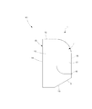
このディスペンサーX1は、特に図1〜3に示すように、その素材が例えばABS樹脂等の合成樹脂、或いは金属素材である筐体1と、この筐体内部に設けられたロールペーパータオル2(以下、単にロールペーパー2ともいう)を回動自在に支持する支持機構と、ロールペーパータオル2から巻き出されたロールペーパータオル2の自由先端部分であるペーパータオル20をニップした状態で回転する排紙ローラ4と、排紙ローラ4の回転により繰り出されるペーパータオル20を筐体外に露出させる排紙口5とを具備し、前記排紙ローラ4がモーターなどの電力駆動原により回転駆動される。
As shown in FIGS. 1 to 3, the dispenser X1 has a
『ロールペーパータオル』
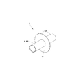
まず、本発明に係るディスペンサーX1に用いるロールペーパータオルから説明する。本発明に係るディスペンサーX1は、特に図4に示されるような、特徴的なロールペーパー2を用いる。本発明に係るディスペンサーに使用するロールペーパー2は、長尺の帯状のペーパータオルが円筒状の紙管21に巻かれ、かつ前記紙管21がペーパータオルが巻かれて成る円筒部分22の少なくとも一方の端面22Lから突出している。本発明に係るディスペンサーX1では、かかるロールペーパー2の紙管21の突出部分21Pを支承するように支持することで省電力化等本願発明の課題解決・目的を達成する。詳細は後述する。
"Roll paper towel"
First, the roll paper towel used for the dispenser X1 according to the present invention will be described. The dispenser X1 according to the present invention uses a
なお、紙管自体は、従来公知の紙管の構成を採用できる。また、紙管の外径はこの種のロールペーパータオルに用いられている一般的な径とすることができる。具体例を述べれば、外径は30〜45φmmである。外周面については本発明では平滑であるのが望ましい。材質はコートボール紙が例示でき、構造は長尺の紙管原紙を巻いてなる構造が例示できる。なお、紙管の坪量は、強度保持の観点、突出部分を手で掴んだときに潰れない等の点から、500〜900g/m2であるのが望ましい。なお、紙管は通常2枚〜3枚の紙管原紙を螺旋状に貼り合せて形成されており、ここでの坪量とは、その紙管原紙の米坪の合計を意味する。 The paper tube itself can adopt a conventionally known paper tube configuration. Further, the outer diameter of the paper tube can be a general diameter used for this type of roll paper towel. To describe a specific example, the outer diameter is 30 to 45 mm. The outer peripheral surface is preferably smooth in the present invention. The material can be exemplified by coated cardboard, and the structure can be exemplified by a structure in which a long paper tube base paper is wound. The basis weight of the paper tube is preferably 500 to 900 g / m 2 from the viewpoint of maintaining strength and not being crushed when the protruding portion is grasped by hand. In addition, the paper tube is usually formed by laminating two to three paper tube base papers in a spiral shape, and the basis weight here means the total of the US basis weights of the paper tube base papers.
他方、図示例のロールペーパー2では、紙管21が円筒部分22に対して突出する側(図示例において符号21L側)にオフセットされており、円筒部分22の紙管突出側と反対側の芯部分には紙管21が存在していない例となっているが、必ずしもこのようにする必要はなく、円筒部分22の紙管突出側と反対側の端面まで紙管が延在していてもよい。本発明では、前記円筒部分22の一方の端面から紙管21が突出していればよい。
On the other hand, in the illustrated
他方、ロールペーパー2の前記円筒部分22の大きさ、すなわち直径L1及び幅L2は公知のロールペーパータオルの大きさとすることができる。具体的には、直径L1が110〜250mm、幅L2が150〜310mm程度である。直径L1が110mm未満では、十分な厚さのペーパーを必要長さ巻いたものとするのが困難となる。反対に250mmを超えるとディスペンサーをコンパクトにすることが難しくなるとともに重量が重くなり支持機構への負担が増加するので望ましくない。また、幅L2が150mm未満であると拭取りに必要なペーパー幅とすることが難しくなり、300mmを超えるとコンパクトなディスペンサーとすることが困難となる。特に本発明にかかるロールペーパーX1では、紙管21が円筒部分22の一方端部から突出することから、上記例示の幅を超えるとディスペンサーのコンパクト性が極めて悪化する。
On the other hand, the size of the
ここで、本発明に係るロールペーパー2おける紙管21の突出長L3は、前記円筒部分22の幅の10〜15%程度とするのがよい。具体的な数値では、15〜45mmとするのがよい。かかる範囲であると後述する支持機構によって十分にロールペーパー2を支持することが可能となるとともに、ディスペンサーのコンパクト性を悪化させず、使用面にも適する程度の幅のペーパー幅とすることができる。
Here, the protruding length L3 of the
なお、ペーパータオルを構成するクレープ紙の原料、素材、物性等は本発明では限定されない。従来公知のものを本発明の効果を妨げない範囲で適宜採用することができる。
また、紙管を突出させる側は適宜の設計事項であり本願発明では限定されない。
In addition, the raw material of the crepe paper which comprises a paper towel, a raw material, a physical property, etc. are not limited in this invention. A conventionally well-known thing can be suitably employ | adopted in the range which does not inhibit the effect of this invention.
Further, the side from which the paper tube is projected is an appropriate design matter and is not limited in the present invention.
なお、ペーパータオル20を構成するクレープ紙の原料、素材、物性等は本発明では限定されない。従来公知のものを本発明の効果を妨げない範囲で適宜採用することができる。好ましい具体例を述べれば以下のとおりである。
本発明に係るロールペーパーの構成材であるペーパータオルは、バージンパルプ、古紙パルプまたはこれらの混合物のみを紙料として製造することができる。古紙パルプを用いる場合古紙パルプ100% またはバージンパルプを配合してもよい。パルプ繊維の種類は、特に限定されないが、針葉樹パルプを60〜100重量% 、特に好適には80〜100重量% 用い、残量を広葉樹パルプとするのが好ましい。繊維の短い広葉樹パルプを高配合とすることで、繊維配向の影響が低減するとともに、排紙口より露出するペーパータオルをより容易且つ緻密な引き裂くことが可能になる。
In addition, the raw material of a crepe paper which comprises the
The paper towel which is a constituent material of the roll paper according to the present invention can be produced using only virgin pulp, waste paper pulp, or a mixture thereof as a stock. When used paper pulp is used, 100% used paper pulp or virgin pulp may be blended. Although the kind of pulp fiber is not particularly limited, it is preferable to use softwood pulp in an amount of 60 to 100% by weight, particularly preferably 80 to 100% by weight, and a remaining amount of hardwood pulp. By making high-blend hardwood pulp with short fibers, the influence of fiber orientation is reduced, and the paper towel exposed from the paper discharge port can be torn easily and densely.
ペーパータオルの坪量を15〜65g/m2程度とすることができるが、中でも坪量が30〜60g/m2の厚手のものが好ましく、特に坪量が30〜50g/m2のものが好ましい。
また、ペーパータオルは、JIS P 8113(1998)に規定される乾燥引張強度の縦横比が2.0以下であるのが好ましく、1.0〜1.8であるのが特に好ましい。この縦横比は、ワイヤーパートにおけるジェットワイヤー比等、各種抄造条件の変更により調整できる。乾燥引張強度の縦横比(縦方向/横方向)を低く抑えることで、排紙口から露出する部分を切り取るさいの縦裂け(巻き方向への裂け)の発生が低減し、より直線状に近い引き裂きが可能となる。
Although the basis weight of the paper towel can be 15~65g / m 2 about, among them the basis weight thereof is preferably thick 30 to 60 g / m 2, in particular basis weight preferably from 30 to 50 g / m 2 .
Moreover, it is preferable that the aspect ratio of the dry tensile strength prescribed | regulated to JISP8113 (1998) is 2.0 or less, and, especially a paper towel is 1.0-1.8. This aspect ratio can be adjusted by changing various papermaking conditions such as the jet wire ratio in the wire part. By keeping the aspect ratio (longitudinal / lateral) of the dry tensile strength low, the occurrence of vertical tearing (tearing in the winding direction) when cutting the exposed part from the paper exit is reduced, making it more linear Tearing is possible.
また、ペーパータオルは、JIS P 8113(1998)に規定される引張破断伸び(巻き取り方向であり通常縦方向である)が16%以下であるのが好ましく、13%以下であるのが特に好ましい。引張破断伸びは、クレープ加工の程度(所謂クレープ率)により調整することができる。引張破断伸びを低く抑えることにより、排紙口から露出するペーパータオルを切り取る際に加わる引裂力の方向がペーパータオル自身の伸びにより不規則に変化するのが防止され、意図しない縦や斜め方向への裂けの発生を低減することができる。 Further, the paper towel preferably has a tensile breaking elongation (winding direction, usually the vertical direction) as defined in JIS P 8113 (1998) of 16% or less, and particularly preferably 13% or less. The tensile elongation at break can be adjusted by the degree of creping (so-called crepe rate). By keeping the tensile elongation at break low, the direction of the tearing force applied when the paper towel exposed from the paper exit is cut off is prevented from changing irregularly due to the elongation of the paper towel itself, and unintended longitudinal or oblique tearing occurs. Can be reduced.
また、ペーパータオルは、JIS P 8116(2000)に規定される横方向の引裂強度が65gf以下とするのが好ましい。また、引裂強度の縦横比は0.75以上、特に0.8以上が好ましい。横方向の引裂強度は、パルプの配合、叩解度(フリーネス)、引張破断伸び等を変更することにより調整できる。横方向の引裂強度ならびに引裂強度の縦横比がこの範囲内にあると、排紙口から露出するペーパータオルを切り取る際に、引き裂きに要する力が適切となるだけでなく、不要な力が不要な方向に作用し難くなり、より綺麗に引裂くことができるようになる。 The paper towel preferably has a transverse tear strength of 65 gf or less as defined in JIS P 8116 (2000). The aspect ratio of the tear strength is preferably 0.75 or more, particularly 0.8 or more. The tear strength in the transverse direction can be adjusted by changing the blending of pulp, the degree of beating (freeness), the tensile elongation at break, and the like. When the tear strength in the lateral direction and the aspect ratio of the tear strength are within this range, not only will the force required for tearing be appropriate when cutting the paper towel exposed from the paper outlet, but also in the direction where unnecessary force is unnecessary. It becomes difficult to act on, and it becomes possible to tear more beautifully.
また、ペーパータオルは、JIS P 8124(1998)に準じて測定した坪量を30〜40g/m2程度とする場合、その紙厚は、JIS P 8111(1998)の条件下で、ダイヤルシックネスゲージ(厚み測定器)「PEACOCK G型」(尾崎製作所製)を用いて測定した値において140〜220μmであるのが望ましい。 Further, when the paper towel has a basis weight measured according to JIS P 8124 (1998) of about 30 to 40 g / m 2 , the paper thickness is a dial thickness gauge (under the conditions of JIS P 8111 (1998)). Thickness measuring device) It is desirable that the thickness is 140 to 220 μm in a value measured using “PEACOCK G type” (manufactured by Ozaki Seisakusho).
また、ペーパータオルは、湿潤引張強度(JIS P 8135 1998))の具体的な数値は、縦方向が500〜1500cN/25mmであるのが好ましい。 Moreover, it is preferable that the specific value of the wet tensile strength (JIS P 8135 1998) of the paper towel is 500 to 1500 cN / 25 mm in the longitudinal direction.
さらに、ペーパータオルは、吸水量が、100〜200g/m2であるのが好ましい。なお、ここでの吸水度は、100mm四方に裁断した試験片を網に載せ、この網ごと水の入った容器に浮かせ、試験片に十分に水が浸透した後に引き上げ、30秒間放置した後の試験片の質量を測定し、この測定質量から乾燥時の質量を引き100倍して、算出される1m2当たりの吸水量である。 Further, paper towels, water absorption, preferably from 100 to 200 g / m 2. In addition, the water absorption here refers to a test piece cut into a 100 mm square, placed on a net, floated in a container containing water together with the net, pulled up after sufficient penetration of water into the test piece, and left for 30 seconds. It is the water absorption per 1 m 2 calculated by measuring the mass of the test piece and subtracting the mass at the time of drying from this measured mass by 100.
また、ペーパータオルは、乾燥引張強度(JIS P 8113 1998)は上記縦横比を満たす範囲内で、縦方向が1400〜3000cN/25mm、横方向が600〜1700cN/25mmであるのが好ましい。 The paper towel preferably has a dry tensile strength (JIS P 8113 1998) in the range satisfying the above aspect ratio, and the longitudinal direction is 1400 to 3000 cN / 25 mm and the lateral direction is 600 to 1700 cN / 25 mm.
なお、上記乾燥引張強度、引張破断伸び、引裂強度等の値は1枚の状態における値を意味するものである。
なお、例えば、ペーパータオルを薬液が付与されたものとするのであれば、その塗布方法、塗布薬液、塗布量については限定されない。公知の構成を採用できる。
The values such as the dry tensile strength, tensile elongation at break, and tear strength mean values in a single sheet.
For example, if a paper towel is provided with a chemical, the application method, the applied chemical, and the amount applied are not limited. A known configuration can be employed.
『筐体の構造例』
次いで、本発明の実施形態のロールペーパータオル用ディスペンサーの筐体の構造例について説明する。筐体1は、特に図1〜3及び図5に示すように、前面開放のケース本体10と、ケース本体10の前面開放部分を被覆する蓋体11とで構成され、その下部に前記支持機構に支持されたロールペーパー2から巻き出されたペーパータオル20を筐体外部に露出させる排紙口5を有している。
“Example of housing structure”
Next, a structural example of the housing of the roll paper towel dispenser of the embodiment of the present invention will be described. As shown in FIGS. 1 to 3 and 5 in particular, the
ケース本体10は、天板部12と底板部13と背板部14とこの背板部14の両側縁若しくは両側縁部から手前に延在する左右一対の本体側板部15,15とで構成され、前記背板部14を介して壁面等に設置される。
The case
蓋体11は、上部がケース本体10の天板部12と一連となるような湾曲面部分を有する前板部16と、この前板部16と直角をなして奥側(背板側)に延在する左右一対の蓋体側板部17,17とを有し、ケース本体10の正面側開放部分を被覆すように配置され、前記ケース本体10とともに箱型の筺体1を構成する。
The
また、蓋体11は、ケース本体10に対してハッチ式に取付けられ、引き下げることにより、ケース本体10を前面開放状態にし、筺体内部の支持機構や排紙ローラ4等の内部機構を露出させ、ロールペーパータオル2の交換を可能とする。
The
このようなハッチ式にするにあたっては、蝶番機構18をケース本体10の底板部13の正面側縁と蓋体11の前板部16の下縁に設けるようにすればよい。ケース本体10の天板部12の正面側縁と蓋体11の前板部16の背面側上縁に蝶番機構18を設けて前面を跳ね上げるようにするハッチ式としてもよい。さらには、各本体側板部の上部或いは下部に一対の係止凸部(図示しない)を設け、各蓋体側板部の上部或いは下部に前記係止凸部に対応する一対の係止嵌合孔(図示しない)を設けて、これらを嵌め込むようにして、ケース本体10と蓋体11とを連結するようにしてもよい。この場合、係止凸部と係止嵌合孔とは対をなせばよく、そのどちらがケース本体側であるかは問わない。
In making such a hatch type, the
他方、筐体下部の排紙口5は、ケース本体10の底板部13に形成することができ、図示例では、ケース本体10の底板部13の正面側が天板部12側に向かって傾斜され、その傾斜部分に幅方向細長の排紙口5が形成され、使用者におけるペーパータオルの取り出しを容易なものとしている。
On the other hand, the
また、図示例では、特に図5に示されるように、排紙口5から露出されたペーパータオルの切り取りを容易にすべく、排紙口5に一部かかるようにカッター刃51が取付けられている。図示例ではカッター刃は、鋸刃とされている。なお、このカッター刃は、金属或いは硬質可塑性樹脂などにより形成することができる。また、ロールぺーパーを構成する長尺のペーパータオルに長手方向の適当間隔に裁断を容易にするための裁断用ミシン目線などが設ければ、かかるカッター刃は不要とすることができる。
Further, in the illustrated example, as shown in FIG. 5 in particular, a
『支持機構例1』
次いで、本発明の実施形態のロールペーパータオル用ディスペンサーの支持機構例1について説明する。前記筐体1内に収納される支持機構は、特に図1、図2、図5〜図7に示されるように、背板部14の両側板近傍からそれぞれ前板側(壁面取付け時における手前側)に向かって所定長さ延出する一対の腕部31L,31Rを有し、その腕部31L,31Rの先端に支持部32L,32Rが取付けられている。なお、図示例に限らず腕部31L,31Rは、側板部13から水平方向に突出するように延出している態様であってもよいし、天板部12から垂下するような態様であってもよいし、底板部13から天板部12に向かって起立するものであってもよい。腕部31は、本発明の効果を妨げない範囲で支持部32を所定位置に位置せしめるものであれば、その具体的な態様は限定されない。
"Support mechanism example 1"
Next, a support mechanism example 1 of the dispenser for roll paper towel according to the embodiment of the present invention will be described. As shown in FIGS. 1, 2, and 5 to 7, the support mechanism housed in the
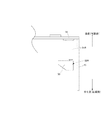
ここで、本発明に係るディスペンサーX1は、特徴的に前記支持部の一方32Lが、背板部側及び前板部側においてそれぞれ上方側(天板部側)に向かって起立する一対の凸片33,33と、これら凸片33,33間にあって前記紙管21の突出部21Pを受ける受面34とで構成される受け部30を有しており、前記紙管21の突出する部分21Pの胴面(円周面)を前記受け部30に載置することで、前記ロールペーパー2の幅方向一方端部が回動自在に支承されるようになっている。
Here, the dispenser X1 according to the present invention is characterized by a pair of convex pieces in which one of the
また、図示例の受け部30は、好ましい例として、各凸片33,33間が、一方の凸片33の頂部33tから前記受面34を介して他方の凸片33の頂部33tに向かって平滑な円弧面又は半筒面の湾曲面とされており、前記紙管21がスムーズに回転するように構成されている。さらに、前記湾曲面の曲率半径が、前記紙管21の断面円の半径とほぼ同等とされて、前記紙管21が前記受け部30に回転可能な状態で嵌合し、ロールペーパー(紙管)の回転時に、紙管21が凸片33,33間でばたつくことがないようになっている。
Moreover, as for the receiving
他方、本例においては前記支持部の他方32Rは、腕部31Rの先端においてディスペンサーの幅方向内側に向かって水平に突出する凸部35を有しており、この凸部35が前記円筒部分22の空芯部22r或いは紙管内に緩挿されて、当該空芯部22r或いは紙管の内面側上部が載置されることで、当該ロールペーパー2の紙管21が突出していない他方側を支持するようになっている。
On the other hand, in the present example, the other 32R of the support part has a
ここで、前記凸部35は、ロールペーパーの回転をスムーズに行えるように、ロールペーパー或いは紙管との当接部分の摩擦が小さくなるようにするのが望ましい。このために、図示はしないが例えば、当該当接部分を平滑面としたり、少なくとも上面側が水平方向を軸心とする半筒状、湾曲面となっているのが望ましい。また、凸部の円筒部分或いは紙管内への挿入を容易とすべく、先端狭窄であるのが望ましい。
Here, it is desirable that the
他方、本例ではこの凸部35は、腕部31Rとの取付け部を回転軸として、先端が上方(天板部側)に移動可能とされており、これにより凸部35の先端を円筒部分の空芯部22rに挿入しやすくしている。
On the other hand, in this example, the
以上の構成の支持機構を有する本実施形態のディスペンサーX1では、ロールペーパー2の幅方向一方端側が紙管21の突出部分21Pの受け部30での支承により支持され、他方側は円筒部分22の空芯部22r或いは紙管内に凸部35が挿入されて支持される。かかる支持機構では、上記受け部30による支持によってロールペーパー回転時のばたつきが防止されるとともに、他方側は、回転を妨げる摩擦が小さくなる。従って、ロールペーパー2より巻き出されたペーパータオルをニップした状態で排紙ローラ5を駆動した際に、かかる排紙ローラ5にかかる負荷が軽減され、駆動原の電力消費を小さくすることができる。
In the dispenser X1 of the present embodiment having the support mechanism configured as described above, one end in the width direction of the
ここで、本支持機構例では、前記凸部35の先端と前記受け部30との間の距離L4が、前記ロールペーパー2の円筒部分22の幅L2の102〜105%であるのが望ましい。かかる範囲であるとロールペーパーが支持機構2から意図せず外れて脱落することが効果的に防止される。
Here, in this example of the support mechanism, it is desirable that the distance L4 between the tip of the
なお、本例では紙面に向かって左側の支持部31Lに受け部30、右側の支持部31Rに凸部35が形成されているが、これらは反対であってもよい。
In this example, the receiving
『支持機構2』
ここで、上記支持機構例1では、支持部の一方31Lに受け部30を設け、他方31Rに凸部35を設けた例であるが、本発明のディスペンサーX1では、図示はしないが、支持機構例1において、一対の支持部31L,31Rの双方に受け部30を設けた構成とすることができる。
この場合、本発明に係るロールペーパー2では、紙管21が幅方向の一方のみに突出していることから、紙管21の突出していない他方を受け部30で受けるようにすべく、特に図9に例示される、支持用部材6を用いる。
"
Here, the support mechanism example 1 is an example in which the receiving
In this case, in the
この支持用部材6は、筒状或いは円柱状の基部60と、その両端面間に周面から突出するように設けられたストッパー部61を有する構造をなしている。使用方法は、前記ストッパー部61より一方端側60Lを前記ペーパータオルが巻かれて成る円筒部分22の空芯部22r内或いは紙管内に挿入し、他方端側60Rを前記円筒部分22より突出させ、その突出部分60Rを支持部31の受け部30で支持するようにして用いる。
The
この支持用部材6は、挿入される部分60Lの外径が前記空芯部22rの内径或いは紙管21の内径とほぼ一致し、突出させる部分60Rの外径が紙管21の外径とほぼ一致しているのが望ましい。完全一致が望ましいが、概ね±1mm程度であれば問題ない。挿入される部分60Lの外径が前記空芯部22rの内径或いは紙管21の内径より過度に大きいと、挿入が困難となり取付けが困難となる。
In the supporting
また、突出させる部分60Rの外径が紙管21の外径と著しく相違しているとロールペーパーの回転時に両端支持部31L,31Rでぶれが生じ、消費電力を小さくする本願発明の効果を発現し難くなる。
Further, if the outer diameter of the projecting
前記ストッパー部61については、過挿入防止及びロールペーパーの回転時のぶれの防止の観点から、図示例のように円盤状であるのが望ましいが、この形態に限定されない。
The
『排紙機構』
他方、本実施形態のディスペンサーX1は、特に図3及び図11から理解されるように、前記支持機構の下方(底板側)に排紙ローラ4を有する。この排紙ローラ4の例は、前記ロールペーパー2を支持機構に取付けたときの軸心と平行な軸心を有する棒状の回転軸41と、その外周の適宜の位置に設けられたゴムロール部42とを有している。そして、対となるニップ手段43とともに前記ロールペーパー2から巻き出されたペーパータオル20を挟持する。図3においては、排紙ローラ及びニップローラの両端支持部は図示を省略している。かかる両端支持部は公知の支持機構を採用できる。前記ニップ手段43としては、前記ゴムロール部41と対になるニップロール或いは、排紙ローラ4に前記ペーパータオルを押し当てるように筐体の前板等に取付けた押えバネなどの押え手段が例示できる(この形態は、図示はしない)。
"Eject mechanism"
On the other hand, the dispenser X1 of the present embodiment has a
ここで本実施形態のディスペンサーX1においては、前記回転軸41が、既知のモーター手段など電力源75からの電力供給によって駆動する駆動源70により回転され、もって排紙ローラ4が電力によって駆動されるものとされている。なお、モーター手段70の軸と前記回転軸とが同軸である必要はなく、図11に例示するようにギア72,72、無端ベルト73、プーリー74などの既知に機構を適宜介在させて前記回転軸41を回転させるようにしてもよい。
Here, in the dispenser X1 of the present embodiment, the rotating
他方、前記モーター手段70の駆動及び停止は、底板部13の外面の排紙口近傍等に設けたセンサー手段により検知された信号に応じて行なわれる。例えば、赤外線などの光学センサーを上記位置にもうけ手を排紙口に近づけたときに、光学センサーがこれを検知してモーター手段に所定時間、モーター手段70を駆動させるようにする。このようにすればモーターの駆動時間に応じて前記排紙ローラが回転された分だけ、排紙口からペーパータオルが露出される。なお、モーター手段の駆動及び停止は上記例示のセンサー手段によるものに限定されない。このほか、前記円筒部分22の回転量を検出するセンサー手段等も採用でき、従来既知のセンサー手段を用いた排紙機構が採用できる。
On the other hand, the motor means 70 is driven and stopped in response to a signal detected by sensor means provided near the paper discharge port on the outer surface of the
以上の本実施形態のディスペンサーX1では、排紙ローラ4とニップロール43とペーパータオル20をニップした状態にて前記モーター手段等によって回転軸41を回転させ、ペーパータオル20を排紙口5から露出させる。すなわち、排紙にともなってロールペーパーが回転される。従って、この際にロールペーパー2がばたつくとペーパータオルが瞬間的に排紙方向(巻きだし方向)と逆方向に移動しようとして、結果的に前記回転軸の正回転を妨げるように作用し回転のための負荷が増加して消費電力が増加することになるが、本発明のディスペンサーでは特徴的なロールペーパー及び支持部の構成により、ロールペーパーがばたつくことがないので、消費電力を増加させるような負荷が排紙ローラにかからない。よって、本願発明のディスペンサーは消費電力が少ないものとなる。
また、かかるばたつき防止がなされていることから、排紙ローラの回転速度を速め、迅速な排紙を達成することもできる。
In the dispenser X1 of the present embodiment described above, the rotating
In addition, since such flapping is prevented, the rotational speed of the paper discharge roller can be increased to achieve quick paper discharge.
『ロールペーパーの取付け(交換)態様1』
次いで、本発明のロールペーパータオル用ディスペンサーX1におけるロールペーパータオル2の取付け態様を、特に図12を参照しながら説明する。
上記支持機構例1では、前記円筒部分22の他方の紙管が突出していない側の当該円筒部分22の空芯部22r或いは紙管内に、前記凸部35を挿入したのち、円筒部分22の一方から突出する紙管21の突出部分21Pを支持部32Lの受け部30に載せるようにしてディスペンサーX1にロールペーパーを取付ける。
"Roll paper installation (replacement)
Next, an installation aspect of the
In the support mechanism example 1, after the
このとき、本発明のディスペンサーX1では、紙管21の突出部21Pを手で掴み、又は円筒部分22の内側に指を差し込み、又はその組み合わせで円筒部分22に触れることなく、ロールペーパー2の取り付けを行なうことができる。従って、濡れた手で交換しても、円筒部分22にかかるペーパータオル20を濡らしてしまうことがない。
At this time, in the dispenser X1 of the present invention, the
『ロールペーパーの取付け(交換)態様2』
他方、上記支持機構例2では、ロールペーパー2の円筒部分22の一方から突出する紙管21の突出部分21Pを手で持ち、前記円筒部分22の他方の紙管21が突出していない側の当該円筒部分22の空芯部22r或いは紙管内に、取付用部材6の一部61Lを挿入し、その後、前記紙管21の突出部分21Pと取付用部材6の突出部分61Rとを一対の支持部32L,32Rの各受け部30に載せるようにしてディスペンサーX1にロールペーパー2を取付ける。この場合においても、本発明のディスペンサーX1では、紙管21の突出部22を手で掴み、円筒部分22に触れることなく、ロールペーパー2の取り付けを行なうことができる。従って、濡れた手で交換しても、円筒部分22にかかるペーパータオル20を濡らしてしまうことがない。また片手で作業できるため、狭い場所でも問題なくロールの取替えが可能である。
"Attachment (exchange)
On the other hand, in the support mechanism example 2, the protruding
『ロールペーパーの製造方法』
ここで、本発明のロールペーパータオル用ディスペンサーに用いる上述のロールペーパーの製造方法について説明する。本発明に係るロールペーパー2は、ペーパータオルが巻かれてなる円筒部分22の一方端面から紙管が突出するものであるが、このロールペーパーは、円筒部分22の両端から紙管を突出させるものと比較して、既存設備のロールペーパーの製造設備を小改良して製造することができる。
"Method for manufacturing roll paper"
Here, the manufacturing method of the above-mentioned roll paper used for the dispenser for roll paper towels of this invention is demonstrated. In the
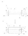
その製造方法は、まず、帯状の紙管原紙を芯棒に巻き付けて長尺の紙管を製造し、その後に前記心棒が挿入されている長尺の紙管をスリットして適当な長さの複数の紙管を製造する。かかる状態では、図13(A)に示すように、複数の連接された紙管が一つの心棒80を共有し、スリットS1に連接された複数の紙管21,21…が一本の紙管群28を構成する状態にある。
In the manufacturing method, first, a long paper tube is manufactured by winding a strip-shaped paper tube base paper around a core rod, and then the long paper tube in which the mandrel is inserted is slit to have an appropriate length. Manufacture multiple paper tubes. In this state, as shown in FIG. 13A, a plurality of connected paper tubes share one
次いで、ペーパータオルの製品幅の複数倍幅以上のペーパータオル原紙が巻かれている原反ロール9から当該ペーパータオル原紙90を巻き出し、この巻きだしたペーパータオル原紙をペーパータオル幅にスリットし、そのスリット(図中スリットをS2で示す)されたペーパータオル原紙91を、前記一つの心棒80を共有し、前記複数の紙管が連接されてなる紙管群28に巻き付ける。なお、既知の方法にしたがいスリットに先立って、ペーパータオル原紙の幅方向両側部をトリムしてもよい。この際、巻きつけ最初に糊付けする場合には、後述の引出し部と紙管が接する部分に糊を付与しない。
Next, the paper
そして、上記巻き付けを行なう際に、図13(B)に示されるように、紙管群28の一方端28tがペーパータオル原紙91の側部から突出した状態となるようにして巻き取り工程を行なう。すなわち、一本様をなす紙管群28がペーパータオル原紙91に対して一方端側にオフセットされた状態で巻き取り工程を行なう。
When the winding is performed, the winding process is performed so that one
この結果、図13(C)に示すように、複数のロールペーパー2,2…が同時に形成されるが、これらのロールペーパー2,2…は、巻取りが終了した時点では、隣接するロールペーパー同士で紙管の一部21P,21P…を共有する状態に巻かれている。すなわち、最も一方端側に位置するロールペーパーを除き、ロールペーパーの円筒部分から突出する紙管部分が、隣接するロールペーパーの円筒部分の空芯部に挿入された状態となっている。
As a result, as shown in FIG. 13C, a plurality of
そして、かかる状態から、図13(D)に示されるように、心棒を引き抜き、その後に紙管の共有を解除して、すなわち、空芯部に挿入されている紙管部分を引き抜くようにして、各ロールペーパーを分離させることで、本願発明のロールペーパーが複数同時に製造される。 Then, from this state, as shown in FIG. 13D, the mandrel is pulled out, and then the sharing of the paper tube is released, that is, the paper tube portion inserted in the air core is pulled out. By separating each roll paper, a plurality of roll papers of the present invention are manufactured simultaneously.
なお、従来のロールペーパータオルの製造は、上記巻き取り工程において、紙管群に対してペーパータオル原紙をオフセットさせずに巻き付けることで行なっている。従って、本発明のロールペーパーは、この巻き取り工程時に紙管群に対してペーパータオル原紙をオフセットさせるということのみで達成することができ、既存の製造設備をオフセットにともなう小改良のみで対応することが可能である。 In addition, the manufacture of the conventional roll paper towel is performed by winding the paper towel base paper around the paper tube group without offset in the winding process. Therefore, the roll paper of the present invention can be achieved only by offsetting the paper towel base paper with respect to the paper tube group at the time of the winding process, and can cope with the existing manufacturing equipment only by a small improvement accompanying the offset. Is possible.
また、円筒部分22の両端から紙管を突出させたロールペーパーは、端面が揃わず製造が困難である。従って、例えば、上記支持機構例2のような場合には、円筒部分22の両端から紙管を突出させたロールペーパーを用いることとするよりも、取付用部材6を用いることとしたほうが、ロールペーパーの製造の観点から望ましいのである。
Moreover, the roll paper in which the paper tube protrudes from both ends of the
なお、上述の製造方法例では紙管の共有部分が円筒部分22から突出する紙管の部分となる。上記「ロールペーパー」の欄で説明した突出部分の長さL3とすると各ロールペーパーの分離が容易であり、かかる製造方法の観点からも上述の突出部分の長さL3とするのがよい。
In the example of the manufacturing method described above, the shared portion of the paper tube becomes a portion of the paper tube protruding from the
X1,X2…ロールペーパータオル用ディスペンサー、1…筐体、2…ロールペーパータオル、20…ペーパータオル、21…紙管、21P…紙管の突出部分、22…円筒部分、22L…円筒部分の一方端面、22R…円筒部分の他方端面、30…受け部、31R,31L…腕部、32L,32R…支持部、33…凸片、33t…凸片の頂部、34…受面、35…凸部、4…排紙ローラ、41…回転軸、42…ゴムロール部、43…ニップ手段(ニップローラ)、5…排紙口、51…カッター刃、6…支持用部材、60・・・基部、60L…挿入部、60R…突出部、61…ストッパー部、L1…円筒部分の直径、L2…円筒部分の幅、L3…紙管の突出部分の長さ、L4…凸部先端と受け部との間の距離、10…ケース本体、11…蓋体、12…天板部、13…底板部、14…背板部、15…本体側板部、16…前板部、17…蓋体側板部、18…蝶番機構、70…モーター手段(排紙ローラの駆動原)、72…ギア、73…無端ベルト、74…プーリー、75…電力源、28…紙管群、80…心棒、9…原反ロール、90…ペーパータオル原紙、91…スリットされたペーパータオル原紙、S1,S2…スリット。
X1, X2 ... dispenser for roll paper towel, 1 ... housing, 2 ... roll paper towel, 20 ... paper towel, 21 ... paper tube, 21P ... protruding portion of paper tube, 22 ... cylindrical portion, 22L ... one end face of cylindrical portion, 22R ... the other end face of the cylindrical part, 30 ... receiving part, 31R, 31L ... arm part, 32L, 32R ... supporting part, 33 ... convex piece, 33t ... top part of convex piece, 34 ... receiving face, 35 ... convex part, 4 ...
Claims (3)
このロールペーパータオル用ディスペンサーは、長尺の帯状のペーパータオルが紙管に巻かれ、かつ前記紙管がペーパータオルが巻かれて成る円筒部分の少なくとも一方の端面から突出しているロールペーパータオルに用いられるものであり、
前記ロールペーパータオルの支持機構が、筐体側部においてロールペーパータオルを支持する一対の支持部からなり、
その一対の支持部の一方が、前記紙管の突出する部分の筒面を回動自在に支承する受け部を有し、一対の支持部の他方が、紙管又は紙管のない空芯部分に緩挿される凸部を有する、ことを特徴とするロールペーパータオル用ディスペンサー。 A support mechanism for supporting the roll paper towel inside the housing, a paper discharge roller for discharging the paper towel unwound from the roll paper towel, and a paper towel fed out by rotation of the paper discharge roller for exposing the paper towel outside the housing A roll paper towel dispenser, wherein the paper discharge roller is rotationally driven by electric power.
This dispenser for roll paper towel is used for a roll paper towel in which a long belt-shaped paper towel is wound around a paper tube and the paper tube protrudes from at least one end surface of a cylindrical portion formed by winding the paper towel. ,
The roll paper towel support mechanism comprises a pair of support parts that support the roll paper towel on the side of the housing,
One of the pair of support portions, have a receiving portion for supporting the cylindrical surface of the projecting portion of the paper tube rotatably, the other of the pair of support portions, the air-core portion without paper tube or paper tube A roll paper towel dispenser characterized by having a convex part that is loosely inserted into the roll paper towel.
このロールペーパータオル用ディスペンサーは、長尺の帯状のペーパータオルが紙管に巻かれ、かつ前記紙管がペーパータオルが巻かれて成る円筒部分の一方の端面から突出しているロールペーパータオルに用いられるものであり、
ペーパータオルが巻かれて成る円筒部分の紙管が突出していない他方の端面に一部が挿入され、一部がその他方の端面から突出される支持用部材を有し、
前記ロールペーパータオルの支持機構が、筐体側部において前記ロールペーパータオルを支持する一対の支持部からなり、
前記支持部は、一方が前記紙管の突出する部分の筒面を回動自在に支承する受け部とされ、他方が前記支持用部材のペーパータオルが巻かれて成る円筒部分から突出する部分を受ける受け部とされ、紙管の突出する部分と、前記支持用部材のペーパータオルが巻かれて成る円筒部分から突出する部分とを各受け部に受けて回動自在に支承するように構成されている、ことを特徴とするロールペーパータオル用ディスペンサー。 A support mechanism for supporting the roll paper towel inside the housing, a paper discharge roller for discharging the paper towel unwound from the roll paper towel, and a paper towel fed out by rotation of the paper discharge roller for exposing the paper towel outside the housing A roll paper towel dispenser, wherein the paper discharge roller is rotationally driven by electric power.
This dispenser for roll paper towel is used for a roll paper towel in which a long belt-shaped paper towel is wound around a paper tube, and the paper tube protrudes from one end surface of a cylindrical portion formed by winding the paper towel,
A part of the cylindrical tube around which the paper towel is wound is inserted into the other end surface where the paper tube does not protrude, and a supporting member is protruded from the other end surface;
The roll paper towel support mechanism comprises a pair of support parts that support the roll paper towel on the side of the housing,
One of the support portions is a receiving portion that rotatably supports the cylindrical surface of the protruding portion of the paper tube, and the other is a portion that protrudes from a cylindrical portion formed by winding the paper towel of the supporting member. The receiving portion is configured to receive the protruding portion of the paper tube and the portion protruding from the cylindrical portion around which the paper towel of the supporting member is wound by each receiving portion so as to be rotatably supported. A roll paper towel dispenser characterized by that.
Priority Applications (1)
| Application Number | Priority Date | Filing Date | Title |
|---|---|---|---|
| JP2010222686A JP5669505B2 (en) | 2010-09-30 | 2010-09-30 | Roll paper towel dispenser |
Applications Claiming Priority (1)
| Application Number | Priority Date | Filing Date | Title |
|---|---|---|---|
| JP2010222686A JP5669505B2 (en) | 2010-09-30 | 2010-09-30 | Roll paper towel dispenser |
Related Child Applications (1)
| Application Number | Title | Priority Date | Filing Date |
|---|---|---|---|
| JP2012066757A Division JP5744782B2 (en) | 2012-03-23 | 2012-03-23 | Roll paper towel and method for producing roll paper towel |
Publications (3)
| Publication Number | Publication Date |
|---|---|
| JP2012075605A JP2012075605A (en) | 2012-04-19 |
| JP2012075605A5 JP2012075605A5 (en) | 2012-06-07 |
| JP5669505B2 true JP5669505B2 (en) | 2015-02-12 |
Family
ID=46236581
Family Applications (1)
| Application Number | Title | Priority Date | Filing Date |
|---|---|---|---|
| JP2010222686A Active JP5669505B2 (en) | 2010-09-30 | 2010-09-30 | Roll paper towel dispenser |
Country Status (1)
| Country | Link |
|---|---|
| JP (1) | JP5669505B2 (en) |
Cited By (1)
| Publication number | Priority date | Publication date | Assignee | Title |
|---|---|---|---|---|
| USD790872S1 (en) | 2015-12-28 | 2017-07-04 | Kimberly-Clark Worldwide, Inc. | Paper product dispenser |
Families Citing this family (1)
| Publication number | Priority date | Publication date | Assignee | Title |
|---|---|---|---|---|
| CN109730568A (en) * | 2019-02-22 | 2019-05-10 | 杭州数策指今科技有限公司 | A kind of roller regulating mechanism of Desktop Share paper napkin machine |
Family Cites Families (2)
| Publication number | Priority date | Publication date | Assignee | Title |
|---|---|---|---|---|
| JPH045275Y2 (en) * | 1987-05-29 | 1992-02-14 | ||
| JP5572300B2 (en) * | 2008-09-18 | 2014-08-13 | 日本製紙クレシア株式会社 | Paper towel roll body |
-
2010
- 2010-09-30 JP JP2010222686A patent/JP5669505B2/en active Active
Cited By (1)
| Publication number | Priority date | Publication date | Assignee | Title |
|---|---|---|---|---|
| USD790872S1 (en) | 2015-12-28 | 2017-07-04 | Kimberly-Clark Worldwide, Inc. | Paper product dispenser |
Also Published As
| Publication number | Publication date |
|---|---|
| JP2012075605A (en) | 2012-04-19 |
Similar Documents
| Publication | Publication Date | Title |
|---|---|---|
| CA2148727C (en) | Paper towel dispenser for dispensing towelling from inside diameter of roll | |
| US10512370B2 (en) | Multiple orifice nozzle with cavity | |
| US3995582A (en) | Moist tissue dispensing | |
| CA2404416C (en) | Roll of wet wipes | |
| RU2376924C2 (en) | Rolled-up sheet discharge device | |
| AU2001253196A1 (en) | Roll of wet wipes | |
| WO2001076436A1 (en) | Wipes dispensing system | |
| WO2016032627A1 (en) | Dispenser apparatus with damper for dispensing paper toweling | |
| JP5497323B2 (en) | Roll paper dispenser | |
| US20110068129A1 (en) | Sheet roll dispenser | |
| JP5744782B2 (en) | Roll paper towel and method for producing roll paper towel | |
| EP1551267A1 (en) | A dispensing apparatus for web material | |
| US6161795A (en) | Surface unwind jumbo roll tissue dispenser | |
| JP5669505B2 (en) | Roll paper towel dispenser | |
| US6302351B1 (en) | Dispenser for multiple rolls of sheet material | |
| US6659391B1 (en) | Method for dispensing wet wipes | |
| US3167367A (en) | Sheet material dispenser | |
| JP2012075605A5 (en) | ||
| JP5551729B2 (en) | Roll paper towel dispenser | |
| US6702227B1 (en) | Wipes dispensing system | |
| JP5551557B2 (en) | Roll paper towel dispenser | |
| JP5635550B2 (en) | Roll paper towel dispenser | |
| JP5635354B2 (en) | Roll paper towel dispenser | |
| JP2012075606A5 (en) | ||
| JP2012075607A5 (en) |
Legal Events
| Date | Code | Title | Description |
|---|---|---|---|
| A521 | Request for written amendment filed |
Free format text: JAPANESE INTERMEDIATE CODE: A523 Effective date: 20120323 |
|
| A621 | Written request for application examination |
Free format text: JAPANESE INTERMEDIATE CODE: A621 Effective date: 20130927 |
|
| A977 | Report on retrieval |
Free format text: JAPANESE INTERMEDIATE CODE: A971007 Effective date: 20140521 |
|
| A131 | Notification of reasons for refusal |
Free format text: JAPANESE INTERMEDIATE CODE: A131 Effective date: 20140530 |
|
| A521 | Request for written amendment filed |
Free format text: JAPANESE INTERMEDIATE CODE: A523 Effective date: 20140725 |
|
| TRDD | Decision of grant or rejection written | ||
| A01 | Written decision to grant a patent or to grant a registration (utility model) |
Free format text: JAPANESE INTERMEDIATE CODE: A01 Effective date: 20141121 |
|
| A61 | First payment of annual fees (during grant procedure) |
Free format text: JAPANESE INTERMEDIATE CODE: A61 Effective date: 20141216 |
|
| R150 | Certificate of patent or registration of utility model |
Ref document number: 5669505 Country of ref document: JP Free format text: JAPANESE INTERMEDIATE CODE: R150 |
|
| R250 | Receipt of annual fees |
Free format text: JAPANESE INTERMEDIATE CODE: R250 |
|
| R250 | Receipt of annual fees |
Free format text: JAPANESE INTERMEDIATE CODE: R250 |
|
| R250 | Receipt of annual fees |
Free format text: JAPANESE INTERMEDIATE CODE: R250 |
|
| R250 | Receipt of annual fees |
Free format text: JAPANESE INTERMEDIATE CODE: R250 |
|
| R250 | Receipt of annual fees |
Free format text: JAPANESE INTERMEDIATE CODE: R250 |
|
| R250 | Receipt of annual fees |
Free format text: JAPANESE INTERMEDIATE CODE: R250 |