JP5667508B2 - Base station, interference control method, and radio communication system - Google Patents
Base station, interference control method, and radio communication system Download PDFInfo
- Publication number
- JP5667508B2 JP5667508B2 JP2011103468A JP2011103468A JP5667508B2 JP 5667508 B2 JP5667508 B2 JP 5667508B2 JP 2011103468 A JP2011103468 A JP 2011103468A JP 2011103468 A JP2011103468 A JP 2011103468A JP 5667508 B2 JP5667508 B2 JP 5667508B2
- Authority
- JP
- Japan
- Prior art keywords
- base station
- time
- downlink
- pattern
- uplink
- Prior art date
- Legal status (The legal status is an assumption and is not a legal conclusion. Google has not performed a legal analysis and makes no representation as to the accuracy of the status listed.)
- Active
Links
Images


Classifications
-
- H—ELECTRICITY
- H04—ELECTRIC COMMUNICATION TECHNIQUE
- H04L—TRANSMISSION OF DIGITAL INFORMATION, e.g. TELEGRAPHIC COMMUNICATION
- H04L1/00—Arrangements for detecting or preventing errors in the information received
- H04L1/12—Arrangements for detecting or preventing errors in the information received by using return channel
- H04L1/16—Arrangements for detecting or preventing errors in the information received by using return channel in which the return channel carries supervisory signals, e.g. repetition request signals
- H04L1/18—Automatic repetition systems, e.g. Van Duuren systems
- H04L1/1867—Arrangements specially adapted for the transmitter end
- H04L1/1893—Physical mapping arrangements
-
- H—ELECTRICITY
- H04—ELECTRIC COMMUNICATION TECHNIQUE
- H04W—WIRELESS COMMUNICATION NETWORKS
- H04W72/00—Local resource management
- H04W72/50—Allocation or scheduling criteria for wireless resources
- H04W72/54—Allocation or scheduling criteria for wireless resources based on quality criteria
- H04W72/542—Allocation or scheduling criteria for wireless resources based on quality criteria using measured or perceived quality
Description
本発明は、基地局、干渉制御方法及び無線通信システムに係り、セルラ無線通信システムの自律的な干渉分散制御、特に、直交周波数分割多重(OFDMA:Orthogonal Frequency Division Multiple Access)方式を採用したセルラ無線通信システムにおいて、複数の小型基地局を配置した際の干渉制御を行う基地局、干渉制御方法及び無線通信システムに関する。 The present invention relates to a base station, an interference control method, and a radio communication system, and more particularly to a cellular radio communication system that uses autonomous interference dispersion control, and more particularly, a cellular radio that employs an Orthogonal Frequency Division Multiple Access (OFDMA) scheme. The present invention relates to a base station that performs interference control when a plurality of small base stations are arranged, an interference control method, and a radio communication system.
近年、OFDMA方式を採用したFDD(Frequency Division Duplex)セルラ無線通信システムの開発が盛んに行われている。日本では、OFDMAを採用したセルラ無線通信システムは、第3.9世代のシステムと呼称されている。代表規格として、LTE(Long Term Evolution)やUMB(Ultra Mobile Broadband)があり、これらはそれぞれ、3GPP(3rd Generation Partnership Project)や3GPP2という企業団体により国際的な標準規格化が行われている。 In recent years, FDD (Frequency Division Duplex) cellular radio communication systems employing the OFDMA scheme have been actively developed. In Japan, a cellular radio communication system employing OFDMA is called a 3.9th generation system. Representative standards include LTE (Long Term Evolution) and UMB (Ultra Mobile Broadband), which have been internationally standardized by corporate organizations such as 3GPP (3rd Generation Partnership Project) and 3GPP2, respectively.
無線通信システムでは、基地局とコアネットワークで構成される無線ネットワークに端末がアクセスする。基地局がカバーするエリアをセルと呼び、そのセル半径の大きさなどによりマクロセル、ピコセル、フェムトセルなどと呼ばれることがある。基本的な通信手段としては、基地局へ所属する端末が、基地局に対して要求を出すことで、コアネットワークを通して、同じ基地局、あるいは別の基地局に所属する端末との通話を実現する。データ通信も同様に基地局に対して端末が要求を出すことで実現する。 In a wireless communication system, a terminal accesses a wireless network composed of a base station and a core network. An area covered by a base station is called a cell, and may be called a macro cell, a pico cell, a femto cell, or the like depending on the size of the cell radius. As a basic communication means, a terminal belonging to a base station issues a request to the base station, thereby enabling a call with a terminal belonging to the same base station or another base station through the core network. . Similarly, data communication is realized when a terminal issues a request to the base station.
OFDMAを用いた無線通信システムは、隣接セルからの電波干渉によって通信品質が劣化する事が知られている。特にセルエッジにおいては、隣接セルからの干渉電力レベルと自セルからの所望信号レベルが拮抗した値になり、例えばチャネル品質を現す指標のひとつであるSINR(Signal to Interference and Noise power Ratio)の劣化という形で顕著に現れる。セルエッジに限らず、システム全体としての容量を向上させるためには、隣接セル間の干渉を低減する事が重要である。このため、隣接セル間同士で、高電力で無線信号を送信できる周波数帯を分けて、その周波数帯を使用してセルエッジ(セルの端)をカバーする技術であるFFR(Fractional Frequency Reuse)の採用が効果的で有る事が知られている。FFRを適用すると、セルセンタ端末とセルエッジ端末を区別して、無線リソースの割当と電力を調整する。FFRを用いない場合、全帯域(f0)で等電力送信し、セルセンタ(基地局近傍)とセルエッジで分け隔てなくスケジューリングできるが、セルエッジにおいて隣接セル間で大きな干渉が発生してしまう。そこで、周波数帯域(f0)を分割(f1、f2、f3)し、それぞれの周波数帯で出力できる電力を調節し、セルごとにその組合せ(f1、f2、f3)を適切に選択する事により、隣接セル間の干渉を抑制できる。 A wireless communication system using OFDMA is known to deteriorate communication quality due to radio wave interference from an adjacent cell. In particular, at the cell edge, the interference power level from the adjacent cell and the desired signal level from the own cell are antagonized. For example, the deterioration of SINR (Signal to Interference and Noise power Ratio), which is one of the indexes indicating the channel quality. Prominent in form. In order to improve not only the cell edge but also the capacity of the entire system, it is important to reduce interference between adjacent cells. For this reason, FFR (Fractional Frequency Reuse), which is a technology that covers the cell edge (cell edge) by dividing the frequency band in which wireless signals can be transmitted with high power between adjacent cells and using the frequency band, is adopted. Is known to be effective. When FFR is applied, the cell center terminal and the cell edge terminal are distinguished, and radio resource allocation and power are adjusted. When FFR is not used, equal power transmission can be performed in the entire band (f0) and scheduling can be performed without separation between the cell center (near the base station) and the cell edge, but large interference occurs between adjacent cells at the cell edge. Therefore, by dividing the frequency band (f0) (f1, f2, f3), adjusting the power that can be output in each frequency band, and appropriately selecting the combination (f1, f2, f3) for each cell, Interference between adjacent cells can be suppressed.
OFDMA方式を採用したマクロセル基地局においては、FFRを用いてセル間干渉の発生を抑圧していた。しかし、例えばフェムトセル基地局やピコセル基地局などの、マクロセル基地局と比べてセルが比較的小さい(電波到達範囲が比較的狭い)基地局で、マクロセルで行われるFFRをそのまま適用するのは困難が伴う。特に、フェムトセルにはFFRに必須となる隣接セルの周波数割当情報を取得するためのインタフェースが存在しない。よって、隣接セルの周波数割当情報に応じて、自セルの割当を動的に変更して干渉を避ける事は困難である。また、このような小型の基地局はマクロセル基地局に比べて高密度で配置することも想定されており、周波数割当情報を取得できたとしても制御が非常に困難である。またセル半径がもともと小さいことから、セルセンタとセルエッジの端末を区別するFFRを実現することは効率的でない。 In a macro cell base station that employs the OFDMA scheme, the occurrence of inter-cell interference is suppressed using FFR. However, it is difficult to apply FFR performed in a macro cell as it is in a base station having a relatively small cell (relative range of radio waves) compared to a macro cell base station, such as a femto cell base station or a pico cell base station. Is accompanied. In particular, the femtocell does not have an interface for acquiring frequency allocation information of neighboring cells that is essential for FFR. Therefore, it is difficult to avoid interference by dynamically changing the allocation of the own cell according to the frequency allocation information of neighboring cells. In addition, it is assumed that such a small base station is arranged at a higher density than the macro cell base station, and even if the frequency allocation information can be acquired, it is very difficult to control. In addition, since the cell radius is originally small, it is not efficient to implement FFR for distinguishing between the cell center and the cell edge terminal.
そこで、隣接セルと連携して、時分割多重によってセル間干渉をする上での課題を検討する。隣接セルが、ある時多重パターンで割当を行っていると、自セルはその時多重パターンを避けてリソース割当を実施する。例えば、特許文献1では、NeighborからのDownlink時多重パターンを基地局が検出して、Downlinkの時多重パターンを変更する技術が開示されている。ただし、この技術は、Downlinkの時多重パターンを基地局が測定することから、基地局が下り受信回路を持つ必要があるというオーバーヘッドがある。また、この技術は、CDMA(Code Division Multiple Access)システムをターゲットとしていることから、Uplinkの時多重パターンは、端末が決定している。
In view of this, a problem in inter-cell interference by time division multiplexing in cooperation with adjacent cells is examined. If a neighboring cell performs allocation in a multiplex pattern at a certain time, the own cell performs resource allocation avoiding the multiplex pattern at that time. For example,
本発明は、以上の点に鑑み、セル間の干渉を回避する基地局、干渉制御方法及び無線通信システムを提供することを目的とする。また、本発明は、干渉の回避を図るための時多重パターンの選択手法を提供することを目的とする。さらに、本発明は、基地局が下り受信回路を用いずに、干渉の回避を図るルールで時多重パターンを選択することを目的とする。 An object of this invention is to provide the base station, interference control method, and radio | wireless communications system which avoid the interference between cells in view of the above point. Another object of the present invention is to provide a time-multiplex pattern selection method for avoiding interference. Furthermore, an object of the present invention is to select a time-multiplex pattern with a rule for avoiding interference without using a downlink receiving circuit by a base station.
本発明では、例えば、使用する無線リソースを時間で分割し、基地局またはセル間で時多重を行う事により、セル間の干渉を回避する。送信タイミングが一定の周期となるように、時多重のパターンを作る。基地局は自セルで用いる送信タイミングを、上り干渉電力の測定結果を基準に定める。 In the present invention, for example, interference between cells is avoided by dividing radio resources to be used by time and performing time multiplexing between base stations or cells. A time-multiplexed pattern is created so that the transmission timing has a constant period. The base station determines the transmission timing used in its own cell based on the measurement result of the uplink interference power.
このように基地局間で時多重を行う事により、セル間の干渉を回避する。本発明の基地局は、上り干渉電力を基準に、上り及び下りの時多重パターンを基地局が両方を決定する。基地局には、上りの受信機能は当然ついているので、上りの干渉電力を基準にすることで、下り受信回路を持たなくて良いというメリットを有する。また、OFDMAシステムでは、もともとセル間で時分割多重するルールを持っていない。よって、セル間で守るべき時間に関するルールを設定する必要がある。本発明では、使用する無線リソースの時分割のため、HARQ(Hybrid Automatic Repeat reQuest)のRTT(Round Trip Time)の固定化により、時多重のパターンを生成して、セル間の時多重を行う。 Thus, interference between cells is avoided by performing time multiplexing between base stations. In the base station of the present invention, the base station determines both uplink and downlink time multiplexing patterns based on uplink interference power. Since the base station is naturally provided with an uplink reception function, there is an advantage that it is not necessary to have a downlink reception circuit by using the uplink interference power as a reference. Also, the OFDMA system originally has no rule for time division multiplexing between cells. Therefore, it is necessary to set a rule regarding the time to be protected between cells. In the present invention, for time division of radio resources to be used, time multiplexing patterns are generated by fixing RTT (Round Trip Time) of HARQ (Hybrid Automatic Repeat reQuest), and time multiplexing between cells is performed.
基地局は、上り干渉電力の測定結果に従い、干渉電力の小さい無線リソースを上りの時多重パターンとして選択する。更に、そのタイミングでHARQの応答を返す様に下りの時多重パターンを割り当てる。トラフィックが多い場合には、追加で時多重パターンを割り当てる。トラフィック量の判定には、送信待ちバッファ量や、端末接続数、上位装置とのコネクション数などを用いるとよい。 The base station selects a radio resource with a small interference power as an uplink time multiplexing pattern according to the measurement result of the uplink interference power. Furthermore, a downlink time multiplex pattern is assigned so as to return a HARQ response at that timing. When there is a lot of traffic, an additional time multiplexing pattern is assigned. For determining the traffic volume, it is preferable to use a transmission waiting buffer volume, the number of terminal connections, the number of connections with a host device, and the like.
制御のトリガとしては、初期設定やチャネル及びトラフィックの変動の検出時などがある。チャネルの変動検出方法は、下り通信品質のレポート情報の収集と、上り干渉情報の周期的な監視によって実現できる。トラフィックの変動の検出方法については、定期的に端末数や、バッファ量をチェックすることで実現できる。
例えば、特許文献1に示される技術に対して、本発明は、Uplink(上り)の干渉電力を測定すればよいため、基地局が下り受信回路を持つ必要がない。また、本発明は、基地局側がUplinkの時多重パターンを決定する機能を持っているシステムを対象としている。また、制御チャネルの周波数がバッティングしてしまう課題については、従来技術では対応できない。本発明の手法を用いると、データチャネルだけでなく、制御チャネルも干渉制御の対象に含めることが可能である。
Control triggers include initial settings and detection of channel and traffic fluctuations. The channel fluctuation detection method can be realized by collecting downlink communication quality report information and periodically monitoring uplink interference information. The traffic fluctuation detection method can be realized by periodically checking the number of terminals and the buffer amount.
For example, in contrast to the technique disclosed in
本発明の第1の解決手段によると、
時分割され、送信タイミングが一定の周期となるように定められた複数の時多重パターンのひとつ又は複数を用いて、複数の基地局が端末と通信する無線通信システムにおける前記基地局であって、
少なくとも該周期内の各時多重パターンにおける上り干渉電力を測定する干渉測定部と、
測定された上り干渉電力が最小又は予め定められた閾値より小さい時多重パターンを、上り通信に用いる上り時多重パターンとし、決定された上り時多重パターンから予め定められたタイミングだけシフトしたタイミングの時多重パターンを、下り通信に用いる下り時多重パターンとする時多重パターン決定部と、
決定された上り及び下り時多重パターンを用いて前記端末と通信する通信処理部と
を備える前記基地局が提供される。
本発明の第2の解決手段によると、
時分割され、送信タイミングが一定の周期となるように定められた複数の時多重パターンのひとつ又は複数を用いて、複数の基地局が端末と通信する無線通信システムにおける干渉制御方法であって、
各基地局について、前記端末から前記基地局への上り方向の時多重パターンのタイミングと、前記基地局から前記端末への下り方向の時多重パターンのタイミングとが予め定められたタイミングだけシフトする関係に定められ、
少なくとも該周期内の各時多重パターンにおける上り干渉電力を測定し、
測定された上り干渉電力が最小又は予め定められた閾値より小さい時多重パターンを、上り通信に用いる上り時多重パターンとし、決定された上り時多重パターンから所定タイミングだけシフトしたタイミングの時多重パターンを、下り通信に用いる下り時多重パターンとし、
決定された上り及び下り時多重パターンを用いて前記端末と通信する前記干渉制御方法が提供される。
According to the first solution of the present invention,
The base station in a wireless communication system in which a plurality of base stations communicate with a terminal by using one or a plurality of time-multiplexed patterns that are time-divisionally determined so that the transmission timing is a constant cycle,
An interference measurement unit that measures uplink interference power in each time-multiplexed pattern at least within the period;
When the measured uplink interference power is the minimum or smaller than a predetermined threshold, the time multiplexing pattern is used as the uplink multiplexing pattern used for uplink communication, and the timing is shifted by a predetermined timing from the determined uplink multiplexing pattern. A time multiplex pattern determination unit that sets the multiplex pattern as a downlink multiplex pattern used for downlink communication;
The base station comprising a communication processing unit that communicates with the terminal using the determined uplink and downlink multiplexing patterns is provided.
According to the second solution of the present invention,
An interference control method in a wireless communication system in which a plurality of base stations communicate with a terminal using one or more of a plurality of time-multiplexed patterns that are time-divisionally determined so that the transmission timing has a constant cycle,
For each base station, a relationship in which the timing of the uplink time multiplexing pattern from the terminal to the base station and the timing of the downlink time multiplexing pattern from the base station to the terminal are shifted by a predetermined timing. Stipulated in
Measure the uplink interference power in each time multiplexing pattern at least within the period,
The time multiplexing pattern with the measured uplink interference power being the minimum or smaller than a predetermined threshold is set as the uplink multiplexing pattern used for uplink communication, and the time multiplexing pattern at the timing shifted from the determined uplink multiplexing pattern by a predetermined timing is used. , And the downlink multiplex pattern used for downlink communication,
The interference control method for communicating with the terminal using the determined uplink and downlink multiplexing patterns is provided.
また、他の解決手段によると、
時分割され、送信タイミングが一定の周期となるように定められた複数の時多重パターンのひとつ又は複数を用いて、端末と通信する複数の基地局
を備え、
各基地局において、前記端末から前記基地局への上り方向の時多重パターンのタイミングと、前記基地局から前記端末への下り方向の時多重パターンのタイミングとが予め定められたタイミングだけシフトする関係に定められ、
前記複数の基地局はそれぞれ、
少なくとも該周期内の各時多重パターンにおける上り干渉電力を測定する干渉測定部と、
測定された上り干渉電力が最小又は予め定められた閾値より小さい時多重パターンを、上り通信に用いる上り時多重パターンとし、決定された上り時多重パターンから予め定められたタイミングだけシフトしたタイミングの時多重パターンを、下り通信に用いる下り時多重パターンとする時多重パターン決定部と、
決定された上り及び下り時多重パターンを用いて前記端末と通信する通信処理部と
を有する無線通信システムが提供される。
According to other solutions,
A plurality of base stations that communicate with a terminal using one or a plurality of time-multiplexed patterns that are time-divisionally determined so that the transmission timing has a constant period,
In each base station, a relationship in which the timing of the uplink time multiplexing pattern from the terminal to the base station and the timing of the downlink time multiplexing pattern from the base station to the terminal are shifted by a predetermined timing. Stipulated in
Each of the plurality of base stations is
An interference measurement unit that measures uplink interference power in each time-multiplexed pattern at least within the period;
When the measured uplink interference power is the minimum or smaller than a predetermined threshold, the time multiplexing pattern is used as the uplink multiplexing pattern used for uplink communication, and the timing is shifted by a predetermined timing from the determined uplink multiplexing pattern. A time multiplex pattern determination unit that sets the multiplex pattern as a downlink multiplex pattern used for downlink communication;
A wireless communication system is provided that includes a communication processing unit that communicates with the terminal using the determined uplink and downlink multiplexing patterns.
本発明によると、セル間の干渉を回避する基地局、干渉制御方法及び無線通信システムを提供することができる。また、本発明によると、干渉の回避を図るための時多重パターンの選択手法を提供することができる。さらに、本発明によると、基地局が下り受信回路を用いずに、干渉の回避を図るルールで時多重パターンを選択することができる。 According to the present invention, it is possible to provide a base station, an interference control method, and a wireless communication system that avoid interference between cells. Further, according to the present invention, it is possible to provide a time-multiplex pattern selection method for avoiding interference. Furthermore, according to the present invention, the base station can select a time-multiplex pattern with a rule for avoiding interference without using a downlink receiving circuit.
本発明を実施する為の形態について、いくつかの実施の形態を挙げて説明する。これらの実施の形態は、個別で実施しても良いが、組合せて実施しても良い。以下の説明において、図中で同じ符号番号がついたものは、同様の動作を行うため、説明を省略する。
1.第一の実施の形態
図1は、セルラ無線通信システムの構成及び基地局配置の例を示す図である。
セルラ無線通信システムは、例えば、複数の基地局1201を備える。基地局1201は、自身のセル内の端末1203と無線で通信する。基地局1201は、バックホール回線を通して、コアネットワーク1202に接続する。
Embodiments for carrying out the present invention will be described with reference to some embodiments. These embodiments may be implemented individually or in combination. In the following description, those with the same reference numerals in the drawings perform the same operation, and thus the description thereof is omitted.
1. First Embodiment FIG. 1 is a diagram illustrating an example of a configuration of a cellular radio communication system and base station arrangement.
The cellular radio communication system includes, for example, a plurality of
図1(b)は、本実施の形態における基地局配置の概念図である。マクロセル基地局と比較して、フェムトセル、ピコセル等の基地局は、高密度に配置される。これらの基地局がカバーするエリアは、マクロセルがカバーするエリアと重なっていても良い。なお、本実施の形態は、フェムトセル、ピコセル等の基地局に限らず適宜の基地局に適用できる。
なお、以下の説明において、複数の基地局のうち注目する基地局を基地局1201−H、その基地局に所属して通信する端末(サービング端末)を端末1203−S、及び、その基地局1201−Hと隣接する基地局に所属してその隣接基地局と通信する端末(又はサービング端末以外の端末)を端末1203−Nと記す。
FIG.1 (b) is a conceptual diagram of the base station arrangement | positioning in this Embodiment. Compared with the macrocell base station, base stations such as femtocells and picocells are arranged with higher density. The area covered by these base stations may overlap with the area covered by the macro cell. In addition, this Embodiment is applicable not only to base stations, such as a femtocell and a picocell, but to an appropriate base station.
In the following description, a base station of interest among a plurality of base stations is the base station 1201-H, a terminal (serving terminal) that belongs to the base station and communicates with the terminal 1203-S, and the base station 1201 A terminal (or a terminal other than the serving terminal) that belongs to a base station adjacent to -H and communicates with the adjacent base station is referred to as a terminal 1203-N.
図2に、本実施の形態の基地局の機能ブロック図に示す。
Transmitter(送信機)411は、基地局1201−Hが、端末1203に対して下り信号を送信するブロックである。下り信号をベースバンド信号からRF(Radio Frequency)信号へ変換する処理も含んでもよい。電波を送信するための送信アンテナも含む。
FIG. 2 is a functional block diagram of the base station according to the present embodiment.
Transmitter (transmitter) 411 is a block in which base station 1201-H transmits a downlink signal to terminal 1203. A process of converting a downstream signal from a baseband signal to an RF (Radio Frequency) signal may also be included. It also includes a transmission antenna for transmitting radio waves.
Receiver(受信機)412は、基地局1201−Hが、端末1203−S及び端末1203−Nからの上り信号を受信するブロックである。上り信号をRF信号からベースバンド信号へ変換する処理を含んでも良い。電波を受信する受信アンテナも含む。送受信アンテナは、共用してよい。本実施の形態では、上り干渉電力を測定することを前提としているため、本機能は上り干渉電力の測定機能(干渉測定部)4121を有する。 The Receiver (receiver) 412 is a block in which the base station 1201-H receives uplink signals from the terminal 1203-S and the terminal 1203-N. A process of converting the upstream signal from the RF signal to the baseband signal may be included. It also includes a receiving antenna that receives radio waves. The transmission / reception antenna may be shared. In this embodiment, since it is assumed that uplink interference power is measured, this function includes an uplink interference power measurement function (interference measurement unit) 4121.
Network I/F(ネットワークインタフェース)413は、基地局1201−Hが、バックホール回線を通して、コアネットワーク1202に接続するためのインタフェースである。コアネットワーク1202に接続する事により、基地局間の情報交換や、モビリティ管理、OAM装置との交信、端末1203が望むデータの送受、通話などの、移動体通信の機能を提供できる。
A network I / F (network interface) 413 is an interface for the base station 1201-H to connect to the
通信処理部418は、L1 Processing Unit(レイヤ1処理部)414と、L2/L3 Processing Unit(レイヤ2、3処理部)415を有し、決定された上り及び下り時多重パターンを用いて端末1203と通信する。
L1 Processing Unit414は、基地局1201−Hが、物理層の信号処理を実施する部位である。送信側の主な処理内容には、例えば適応変調、誤り訂正符号化、レイヤマッピングやPrecodingと呼ばれるMIMO(Multiple Input Multiple Output)の信号処理、及び、FFT(Fast Fourier Transform)がある。受信側の主な処理内容は、例えば送信側で施した変調・符号処理を解くための復調・復号処理である。端末1203に対して送信するデータは、L2/L3 Processing Unit415から取得し、端末1203から取得したデータは、L2/L3 Processing Unit415へ送る。
L2/L3 Processing Unit415は、HARQ(Hybrid Automatic Repeat reQuest)の管理や、割当リソースを決定するスケジューリング処理、パケット加工、無線回線の秘匿化、端末へのシグナリング情報の生成などの機能に加え、セル間干渉制御など、無線リソース管理の機能も有するブロックである。また、時多重パターン決定部417から、スケジューリング処理に関する時間的制約を受けて、無線リソース割り当てを実質的に操作する部位である。
The
The
In addition to functions such as HARQ (Hybrid Automatic Repeat reQuest) management, scheduling processing to determine allocated resources, packet processing, wireless channel concealment, and generation of signaling information to terminals, L2 /
統計情報取得部416は、本実施の形態の処理を実施するために必要な情報を取得するため、統計処理を実施するブロックである。具体的には、時多重パターンごとの上り干渉電力測定結果をメモリ(Measured uplink Iot Table)に格納し、一定時間平均する処理を実施する部位である。
時多重パターン決定部417は、本実施の形態の特徴である、時多重パターンの割り当てを決定する部位である。割り当て結果のパターンはメモリに保持しておく(Assign slot table)。基地局1201−Hが、割り当て決定処理を実施するときに、上り干渉電力測定結果と照らし合わせて使用する。
The statistical
The time-multiplexed
図3に、本実施の形態における基地局1201−Hのハードウェア構成を示す。
メモリ部401には、例えば、統計情報取得部416で用いる上り干渉電力測定結果を保持しておくためのMeasured Uplink IoT Table(上り干渉テーブル)4011と、時多重パターンの割当結果を記憶するAssign slot Table(割当スロットテーブル、割当パターンテーブル)4012と、下りの品質情報を記憶するDownlink quality table(下り品質テーブル)4013とを有する。
FIG. 3 shows a hardware configuration of base station 1201-H in the present embodiment.
In the
また、CPU/DSP部(処理部)402は、本実施の形態の一連の手続きP1001〜P1006を実行するプログラムを読み出し、実行する。例えば、Determination of time slot pattern with/without power control(タイムスロットの決定処理)、Addition of time slot pattern(タイムスロットの追加処理)を実行する。各プログラムは、例えばメモリ部401に格納され、CPU/DSP部402が読み出しても良いし、CPU/DSP部402内部のメモリに格納されていてもよい。
The CPU / DSP unit (processing unit) 402 reads and executes a program for executing a series of procedures P1001 to P1006 of the present embodiment. For example, a determination of time slot pattern with / without power control (time slot determination process) and an addition of time slot pattern (time slot addition process) are executed. Each program may be stored in the
Logic Circuit(論理回路)404は、CPU/DSP部402が実行するプログラムの機能をサポートする。たとえば、L1 Processing Unit414などは、処理高速化のためアクセラレータを利用するとよい。
CPU/DSP部402、Logic Circuit404の処理により、図2に示す各機能が実現される。
I/F部(インタフェース部)403は、無線のアンテナとのインタフェースや、バックホール回線とのインタフェースなどの総称である。
The logic circuit (logic circuit) 404 supports the function of the program executed by the CPU /
Each function shown in FIG. 2 is realized by the processing of the CPU /
The I / F unit (interface unit) 403 is a generic term for an interface with a wireless antenna, an interface with a backhaul line, and the like.
図4に、本実施の形態における初期状態からのフローチャートを示す。第一の実施の形態の動作について、図4のフローチャートを用いて説明する。図4のフローチャートは、例えば電源立ち上げやリセットなどの初期化イベント後、基地局1201−H(例えばフェムトセル基地局)が行う動作について示している。
Initial Setup(P1001)では、基地局(1201−H)は、システムパラメータの初期値を設定する。設定方法は、プリインストールデータの読み込みであってもよいし、管理装置からのコンフィグパラメータのダウンロードであっても良い。設定内容は、例えばRRM(Radio Resource Management)と、外部装置とのインタフェースのためのパラメータである。
FIG. 4 shows a flowchart from the initial state in the present embodiment. The operation of the first embodiment will be described using the flowchart of FIG. The flowchart in FIG. 4 illustrates an operation performed by the base station 1201-H (for example, a femtocell base station) after an initialization event such as power-on or reset.
In the Initial Setup (P1001), the base station (1201-H) sets initial values of system parameters. The setting method may be reading preinstalled data or downloading configuration parameters from the management apparatus. The setting content is, for example, a parameter for an interface between an RRM (Radio Resource Management) and an external device.
初期設定が終了すると、基地局1201−H(例えば干渉制御部4121)は、隣接基地局に所属する端末からの上り干渉電力を測定する(P1002)。ここでは上り干渉電力を測定するため、基地局1201−Hは、自基地局と通信するサービング端末(1203−S)の上り通信を止めておく。少なくとも測定対象の無線リソース(周波数、時間で分割した単位)はとめておくと良いが、それ以外の無線リソースでは通信を継続しても良い。この際、後のステップP1003で使用できるように、時多重パターン(time slot pattern)ごとに干渉電力を測定しておくと良い。測定された干渉電力は、時多重パターン毎に上り干渉テーブル4011に記憶される。 When the initial setting is completed, the base station 1201-H (for example, the interference control unit 4121) measures the uplink interference power from the terminal belonging to the adjacent base station (P1002). Here, in order to measure the uplink interference power, the base station 1201-H stops the uplink communication of the serving terminal (1203-S) communicating with the own base station. At least radio resources to be measured (units divided by frequency and time) should be kept, but communication may be continued with other radio resources. At this time, the interference power may be measured for each time multiplex pattern (time slot pattern) so that it can be used in the subsequent step P1003. The measured interference power is stored in the uplink interference table 4011 for each time multiplexed pattern.
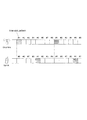
図5に時多重パターンの例を示す。同じ数字がついている送信タイミングを用いることから、時多重パターン(time slot pattern)と呼称している。例えば、端末から基地局への上り方向及び基地局から端末への下りの双方について、時分割された複数の時多重パターンのひとつ又は複数を周期的に用いて、複数の基地局と端末とが通信する。図示の例では、各時多重パターン#1〜#8が繰り返し用いられる。時多重パターンの干渉電力を測定する際は、Timerを設けて一定時間、時多重パターンごとに電力の平均化処理を実施する。平均方法は、忘却平均であっても加算平均であってもかまわない。平均化方法、忘却係数、Timerの時間などはシステムパラメータとして保持しておいてもよいし、プリインストールしておいても良い。Timerの時間は少なくとも時多重パターンの周期よりも長く、図5の例では時多重パターン#1〜#8の干渉電力が測定されるように設定される。上述のように、平均化処理も行う場合は、繰り返し送信される時多重パターンについて干渉電力が複数回測定されるように設定される。
FIG. 5 shows an example of a time multiplexed pattern. Since transmission timings with the same numbers are used, it is called a time slot pattern. For example, for both the uplink direction from the terminal to the base station and the downlink from the base station to the terminal, one or a plurality of time-division time-divided patterns are periodically used, and a plurality of base stations and terminals are connect. In the example shown in the figure, each time multiplexing
上り干渉電力の測定が終了すると、基地局1201−H(例えば時多重パターン決定部417)は、上り通信に使用する時多重パターンを決定する処理を実施する(P1003)。基地局1201−Hは、干渉を測定した結果に従い、隣接基地局所属端末(1203−N)からの干渉電力が小さい時多重パターンを選択し、自セルが使用する上り時多重パターンとする。図6に時多重パターンと測定された上り干渉電力の例を示す。たとえば、図6の場合、基地局1201−Hは、最も干渉電力が小さい時多重パターン601を選択してもよいし、干渉電力が一定のレベル(閾値)以下であった時多重パターンのひとつ(例えば時多重パターン602)を選択しても良い。最小の干渉電力に限定すると、図7に示すように、対象のリソースが一つだけのときに、同時に2つの基地局1201−Hが時多重パターンのリソース割当を始めると、両方が干渉の小さいリソース601を選択し、重複する場合がある。よって、一定レベル以下の干渉の時多重パターンも選択肢に含めてもよい。なお、初期設定で動作する時は、干渉が最小となる時多重パターンを選択し、後述する再割当で動作する時は、一定レベル以下の干渉の時多重パターンからランダム選択するというルールで運用しても良い。
When the uplink interference power measurement is completed, the base station 1201-H (for example, the time multiplexing pattern determination unit 417) performs a process of determining a time multiplexing pattern used for uplink communication (P1003). The base station 1201-H selects a time multiplex pattern with small interference power from the adjacent base station affiliation terminal (1203-N) according to the measurement result of interference, and sets it as the uplink time multiplex pattern used by the own cell. FIG. 6 shows an example of the time multiplexed pattern and the measured uplink interference power. For example, in the case of FIG. 6, the base station 1201-H may select the
上りの送信タイミング(上り通信で用いる時多重パターン)が決まると、基地局1201−Hは、そのタイミングで上りの制御チャネルとデータチャネルの両方を集中的に配置する。たとえば、LTEにおいてはPUCCH(Physical Uplink Control CHannel)とPUSCH(Physical Uplink Shared CHannel)を集中的に割り当ててもよい。 When the uplink transmission timing (time multiplexing pattern used in uplink communication) is determined, the base station 1201-H concentrates both the uplink control channel and the data channel at that timing. For example, in LTE, PUCCH (Physical Uplink Control Channel) and PUSCH (Physical Uplink Shared Channel) may be allocated intensively.
基地局1201−H(例えば時多重パターン決定部417)は、上り時多重パターンが決まると、次に下り時多重パターンを決める(P1004)。無線区間の通信では、HARQと呼ばれる伝送方法(再送制御)が一般的に用いられる。これは送信側からデータ信号を送信すると、受信側からACK信号が返ってくるまで、再送を行う方式である。受信側は信号の復号に失敗するとNAK信号を返し、成功するとACK信号を返す。信号を送信してから、判定信号が帰ってくるまでの時間をRTT(Round Trip Time)と呼ぶ。 When the uplink multiplexing pattern is determined, the base station 1201-H (for example, the time multiplexing pattern determining unit 417) next determines the downlink multiplexing pattern (P1004). In wireless communication, a transmission method called HARQ (retransmission control) is generally used. In this method, when a data signal is transmitted from the transmission side, retransmission is performed until an ACK signal is returned from the reception side. The receiving side returns a NAK signal when the signal decoding fails, and returns an ACK signal when it succeeds. The time from when the signal is transmitted until the determination signal returns is called RTT (Round Trip Time).
下りのデータ送信に対するACK/NAK判定情報を含む上り制御チャネルは、下りの送信することを想定すると、下りの時多重パターンを連動して定めることが出来る。たとえば、E−UTRAでは下りの送信から4サブフレーム(4ms)後に、下りの送信に対する応答を返すことが規定されている。つまり、図8に示すように、上り送信タイミング(例えば図中の601)を決定すれば、4サブフレーム巻き戻すことで下り送信タイミングもパターン化することが出来る。ここで、下りのデータ送信タイミング、つまりHARQのRTTを固定すると、上りと下り両方の送信タイミングを関連付けた上で固定することが可能となる。勿論、上述の4サブフレームは例であり、下りのデータ送信タイミングと、それに対するACK/NAK判定情報を含む上り制御チャネルの送信タイミングを対応させる時間的な決まりがあれば良い。つまり、基地局1201−Hは、選択された上りの時多重パターンの送信タイミングから、予め定められたタイミング前の下りの時多重パターンを選択し、自セルが使用する下り時多重パターンとする。 An uplink control channel including ACK / NAK determination information for downlink data transmission can be determined in conjunction with a downlink time multiplexing pattern, assuming downlink transmission. For example, E-UTRA stipulates that a response to downlink transmission be returned after 4 subframes (4 ms) from downlink transmission. That is, as shown in FIG. 8, if the uplink transmission timing (for example, 601 in the figure) is determined, the downlink transmission timing can also be patterned by rewinding 4 subframes. Here, if downlink data transmission timing, that is, HARQ RTT is fixed, it is possible to fix after associating both uplink and downlink transmission timings. Of course, the above four subframes are examples, and it is sufficient if there is a temporal rule that associates the downlink data transmission timing with the uplink control channel transmission timing including the ACK / NAK determination information. That is, the base station 1201-H selects a downlink time multiplexing pattern before a predetermined timing from the transmission timing of the selected uplink time multiplexing pattern, and sets it as the downlink multiplexing pattern used by the own cell.
下りの時多重パターンが決まると、そのタイミングで下りの制御チャネル、データチャネルの両方を集中的に割り当てると良い。非選択の時多重パターンでは、参照信号と報知情報を含む信号は送信してもよい。これらを送信しておくことで、システムに影響を与えずに本技術での目的を達成できる。たとえば、LTEでは、PDSCH(Physical Downlink Shared CHannel)、PDCCH(Physical Downlink Control CHannel)、およびPHICH(Physical HARQ Indicator CHannel)を集中的に、選択した時多重パターンでのみ送信してよい。例えば非選択の時多重パターンではこれらを割り当てない。 When the downlink time multiplexing pattern is determined, both the downlink control channel and the data channel should be intensively allocated at that timing. In a non-selected time-multiplex pattern, a signal including a reference signal and broadcast information may be transmitted. By transmitting these, the purpose of the present technology can be achieved without affecting the system. For example, in LTE, PDSCH (Physical Downlink Shared Channel), PDCCH (Physical Downlink Control Channel), and PHICH (Physical HARQ Indicator CHannel) may be multiplexed and selected only in a concentrated manner. For example, these are not assigned in a non-selected time multiplexed pattern.
ここで、本実施の形態の処理が行われなかった場合のチャネル割り当てについて、図15を用いて説明する。ある時刻#1で送信された下りHARQに対する応答は、一定時間後に上り制御チャネル(PUCCH: Physical Uplink Control CHannel)701において基地局へフィードバックされる。同様に時刻#3で送信された下りHARQに対する応答は、制御チャネル703において基地局へフィードバックされる。
一方、上りデータチャネル(PUSCH: Physical Uplink Shared CHannel)は、下りデータ信号に対する応答を返す制御チャネル701や703と重畳される制約はない。よって、別のタイムスロットに、上りデータチャネルが割り当てられることもある(702、704)。
Here, channel assignment when the processing of this embodiment is not performed will be described with reference to FIG. A response to the downlink HARQ transmitted at a
On the other hand, the uplink data channel (PUSCH: Physical Up Shared Channel) is not restricted by being superposed on the
また、図15下段に示すように隣接基地局でも全く同様のルールで動く。ここではタイミング#2、#3で送信される下りHARQに対する応答が基地局へフィードバックされる。セル間で協調して動作する仕組みがない場合には、データチャネル、制御チャネル共に、セル間で衝突する可能性がある。また、上りの制御チャネルとデータチャネルが重畳される制約は無いため、704と705のようにデータチャネル同士、あるいは、703と706のように制御チャネル同士が同タイミングで送信される場合がある。
一方、本実施の形態のように、時多重パターンごとに制御チャネルとデータチャネルを重畳して送信する仕組みがあれば、制御チャネル、データチャネル共に隣接セル間干渉を回避することが可能になる。
In addition, as shown in the lower part of FIG. Here, a response to downlink HARQ transmitted at
On the other hand, if there is a mechanism for superimposing and transmitting the control channel and the data channel for each time multiplexing pattern as in the present embodiment, it is possible to avoid interference between adjacent cells in both the control channel and the data channel.
図4に戻り、フローチャートの説明を続ける。P1003及びP1004で上りと下りの時多重パターンの割当が行われるが、基地局1201−Hは、割当てた時多重パターンで、トラフィックを処理できるかどうかを判定する(P1005)。トラフィック量の指標としては、E−RAB(Evolved Packet Service Radio Access Bearer)数、端末接続数、送信待ちバッファサイズなどで判断してよい。これらの指標は基地局1201−Hが適宜監視する。E−RABは、例えば端末とS−GW(ゲートウェイ)の間に張られるコネクションを示す。端末と基地局間のRadio Bearer、基地局とS−GW間のS1 Bearerで構成される。また、送信待ちバッファサイズは、空きバッファサイズでもよい。これらそれぞれについて、時多重パターンを1つ割当てたときに処理できるトラフィックをシステムパラメータとして設定可能な仕組みにしておき、割り当てた時多重パターンの数に応じたトラフィック量を閾値にできるようにしておく。基地局1201−Hは、これら指標の現在値と閾値を比較し、現在値が割り当てた時多重パターンの数に対応する閾値を超えていた場合、時多重パターンが十分でないと判断する(P1005、No)。時多重パターンが不足している場合には、基地局1201−Hは、追加で時多重パターンの割当処理(P1003、P1004)を続ける。閾値を超えていなければ、時多重パターンが十分とみなし、処理P1006へ移る。 Returning to FIG. 4, the description of the flowchart will be continued. Uplink and downlink time multiplexing patterns are assigned in P1003 and P1004, and the base station 1201-H determines whether or not traffic can be processed with the assigned time multiplexing patterns (P1005). As an index of traffic volume, it may be determined by the number of E-RAB (Evolved Packet Service Radio Access Bearer), the number of terminal connections, the transmission waiting buffer size and the like. These indexes are appropriately monitored by the base station 1201-H. E-RAB indicates, for example, a connection established between a terminal and an S-GW (gateway). It is composed of a radio bearer between the terminal and the base station, and an S1 Bearer between the base station and the S-GW. Further, the transmission waiting buffer size may be an empty buffer size. For each of these, a mechanism is set so that traffic that can be processed when one time-multiplex pattern is assigned is set as a system parameter, and a traffic amount corresponding to the number of assigned time-multiplex patterns can be set as a threshold value. The base station 1201-H compares the current value of these indices with a threshold value, and determines that the time multiplexed pattern is not sufficient when the current value exceeds a threshold value corresponding to the number of time multiplexed patterns assigned (P1005, No). When the time multiplexing pattern is insufficient, the base station 1201-H continues the time multiplexing pattern allocation processing (P1003, P1004) additionally. If the threshold value is not exceeded, it is considered that the time multiplexed pattern is sufficient, and the process proceeds to process P1006.
基地局1201−Hは、時多重パターンが十分に割り当たったら、使用する時多重パターンでのみデータチャネルと制御チャネルの割当が行われるように、上りスケジューラ及び下りスケジューラのパラメータをアップデートする(P1006)。たとえば、無線リソースの割当て時刻に制限を加える変更を反映するとよい。より具体的な例として、LTEの下りHARQは、必ずしも周期性を持たなくて良い特長を持っているが、周期的な動きとなるように制約を設けるとよい。 When the time multiplexing pattern is sufficiently allocated, the base station 1201-H updates the parameters of the uplink scheduler and the downlink scheduler so that the data channel and the control channel are allocated only in the time multiplexing pattern to be used (P1006). . For example, it is good to reflect the change which adds a restriction | limiting to the allocation time of a radio | wireless resource. As a more specific example, LTE HARQ in LTE has a feature that does not necessarily have periodicity, but it is preferable that a restriction is provided so as to cause periodic movement.
図9は、図4のフローチャートを実行するために必要な他装置と行う通信を記したシーケンス図である。処理P1001〜P1006は、上述の通りである。上述の手順P1001〜P1006を実施することで、自セルの端末1203−Sと、上り及び下りのデータ通信が可能となる。
本実施の形態によれば、電源立ち上げやリセット後、基地局と端末が通信を開始するまでの間に、スケジューラに対する制約条件を生成し、擬似的に時間多重で動作するOFDMAシステムを構築することが可能となる。
FIG. 9 is a sequence diagram showing communications performed with other apparatuses necessary for executing the flowchart of FIG. Processes P1001 to P1006 are as described above. By performing the above-described procedures P1001 to P1006, uplink and downlink data communication with the terminal 1203-S in the own cell becomes possible.
According to the present embodiment, after the power is turned on or reset, the constraint condition for the scheduler is generated until the base station and the terminal start communication, and an OFDMA system that operates in a pseudo time-multiplexed manner is constructed. It becomes possible.
2.第二の実施の形態
第一の実施の形態では、初期状態から第一の実施の形態の機能を実現する方法及びシステムについて説明した。第二の実施の形態では、通信を開始した定常状態から、本実施の形態の機能を実現する方法及びシステムについて説明する。無線通信システム及び基地局の構成は、第一の実施の形態と同様である。
第二の実施の形態の動作について、図10のフローチャートを用いて説明する。初期状態のフローチャートとの差分は、例えば時多重パターンの再割当が必要と判断する機能が追加され、必要と判断された場合は上述と同様にして時多重パターンを再割当する点である。
2. Second Embodiment In the first embodiment, the method and system for realizing the functions of the first embodiment from the initial state have been described. In the second embodiment, a method and system for realizing the functions of the present embodiment from the steady state where communication is started will be described. The configurations of the radio communication system and the base station are the same as those in the first embodiment.
The operation of the second embodiment will be described using the flowchart of FIG. The difference from the flowchart in the initial state is that, for example, a function for determining that reassignment of the time multiplexed pattern is necessary is added, and when it is determined that reassignment is necessary, the time multiplexed pattern is reassigned in the same manner as described above.
本実施の形態において、時多重パターンを再割当するトリガとしては、例えば以下の場合がある。
(1)上り干渉電力の変化(増加)をトリガに時多重パターンを割り当てる。この場合、例えば基地局で測定する上り干渉電力に基づき変化を検出する。
(2)下り通信品質情報の変化(下り通信品質の低下)をトリガに時多重パターンを割り当てる。下り通信品質情報の具体例として以下がある。
(2−1)CQI等の下りチャネル品質の指標で判断する。
(2−2)アウターループの制御結果で判断する。
(3)トラフィックの変化(増加又は減少)をトリガに時多重パターンを割り当てる。トラフィックの指標の具体例として以下がある。
(3−1)上位装置との間で張られているコネクション数を指標とする。接続ユーザ数でもよい。
(3−2)接続端末数を指標とする。
(3−3)バッファサイズを指標とする。例えば、送信待ちバッファサイズ又は空きバッファサイズを指標とする。
なお、これ以外にも通信品質の変動を適宜の指標により検出して、時多重パターンを再割当してもよい。
In the present embodiment, examples of triggers for reassigning time-multiplexed patterns include the following cases.
(1) A time-multiplex pattern is assigned using a change (increase) in uplink interference power as a trigger. In this case, for example, the change is detected based on the uplink interference power measured by the base station.
(2) A time-multiplex pattern is assigned triggered by a change in downlink communication quality information (decrease in downlink communication quality). Specific examples of downlink communication quality information include the following.
(2-1) Judgment is based on an indicator of downlink channel quality such as CQI.
(2-2) Judgment is made based on the outer loop control result.
(3) A time-multiplex pattern is assigned triggered by a change (increase or decrease) in traffic. Specific examples of traffic indicators are as follows.
(3-1) The number of connections established with the host device is used as an index. It may be the number of connected users.
(3-2) The number of connected terminals is used as an index.
(3-3) The buffer size is used as an index. For example, the transmission waiting buffer size or the empty buffer size is used as an index.
In addition to this, a variation in communication quality may be detected by an appropriate index, and the time multiplexed pattern may be reassigned.
基地局1201―Hは定常状態で動作している時、干渉電力あるいはトラフィックの増加等により、時多重パターンの再割当の必要性があることを検出する機能を有しても良い。また、一定周期ごと、あるいは特定の時刻において、再割当のための処理を行ってもよい。
本実施の形態の機能を有する周辺基地局が同時に動作すると、多重パターンの再割当処理が重複し、干渉を検出し続ける可能性がある。これを防止するため、基地局は、Prohibit timerを備えてもよい。例えば、Prohibit Timerは、前回の割り当て処理の終了時にTimerの開始トリガをかける。同TimerのExpire(満了)するまでの時間はシステムパラメータとして予め設定されることができる。Expire時間(タイマ満了時間)は、本実施の形態の基地局が同一値をもって動作すると、処理期間が重複するため、Expire時間にはランダムオフセットを持たせておくとよい。
When the base station 1201 -H operates in a steady state, it may have a function of detecting the necessity of reassignment of time-multiplexed patterns due to interference power or traffic increase. Further, processing for reassignment may be performed at regular intervals or at specific times.
When neighboring base stations having the functions of the present embodiment operate simultaneously, there is a possibility that the reassignment process of multiple patterns overlaps and interference is continuously detected. In order to prevent this, the base station may include a Prohibit timer. For example, Prohibit Timer triggers a Timer start trigger at the end of the previous allocation process. The time until the expire of the same timer can be preset as a system parameter. The Expire time (timer expiry time) has a processing offset that overlaps when the base station of this embodiment operates with the same value. Therefore, the Expire time may have a random offset.
上記のようなProhibit timerの終了を確認(P1011)し、TimerがExpireしていたら、基地局1201−H(例えば、統計情報取得部416)は、自セルに所属する端末1203−Sからの上り受信電力と、当該端末1203−Sから報告される受信品質の統計情報を収集する。端末1203−Sが報告する受信品質情報には、自セルを含む周辺セルの参照信号の電力強度、下り受信品質情報、通信成功確率(つまりHARQ ACK数)などが含まれていてよい。 When the termination of the Prohibit timer as described above is confirmed (P1011) and the Timer is exposed, the base station 1201-H (for example, the statistical information acquisition unit 416) transmits the uplink from the terminal 1203-S belonging to the own cell. Received power and statistical information of reception quality reported from the terminal 1203-S are collected. The reception quality information reported by terminal 1203-S may include power intensity of reference signals of neighboring cells including its own cell, downlink reception quality information, communication success probability (that is, the number of HARQ ACKs), and the like.
たとえば、E−UTRAならば、RSRP(Reference Signal Received Power)、RSRQ(Reference Signal Received Quality)などといったMeasurement Reportで報告される値や、CQI(Channel Quality Indicator)、RI(Rank Indicator)や、PMI(Precoding Matrix Indicator)などといった下りチャネル品質の情報を示す指標を用いてよい。手順P1012では、これら指標を一定回数分だけメモリに保持していたもの(Downlink quality table)を、統計処理に用いる。具体的には、指標ごとに一定回数分にわたる平均値、確率分布や分散の算出が相当する。 For example, in the case of E-UTRA, values reported in Measurement Report (RSRP (Reference Signal Received Power), RSRQ (Reference Signal Received Quality), etc.), CQI (Channel QualitInd) An index indicating downlink channel quality information such as Precoding Matrix Indicator) may be used. In the procedure P1012, the index (downlink quality table) that has been stored in the memory for a certain number of times is used for statistical processing. More specifically, calculation of an average value, probability distribution, and variance over a certain number of times corresponds to each index.
手順P1013では、基地局1201−Hは、干渉電力(例えば上り干渉電力)の増加、下り通信品質情報の変化あるいはトラフィックの増加を検出する。上り干渉電力は、干渉測定部4121で測定され、例えば上り干渉電力が閾値を越えたことにより、又は、過去の測定値との変動幅が許容値を超えることにより、上り干渉電力の変化を検出する。
下り通信品質情報の変化(例えば下り品質の低下又は下り干渉電力の増加)を検出する具体的な方法としては、手順P1012で算出した、CQI、RI、PMI、RSRP、RSRQについて、平均値あるいは分散を予め定められた閾値と比較する方法を用いても良いし、これらの確率分布が悪い方向に一定量以上シフトしていることをもって検出しても良い。ただし、これらの値は、自セルの時多重パターンを割当てていない部分も含んで平均した値を端末が報告してきている可能性があるので精度が低いことが予想される。そのため、HARQのACK確率を統計する方法を用いても良い。
In procedure P1013, the base station 1201-H detects an increase in interference power (for example, uplink interference power), a change in downlink communication quality information, or an increase in traffic. The uplink interference power is measured by the
As a specific method for detecting a change in downlink communication quality information (for example, a decrease in downlink quality or an increase in downlink interference power), the average value or variance of CQI, RI, PMI, RSRP, and RSRQ calculated in procedure P1012 May be used, or may be detected when these probability distributions are shifted by a certain amount or more in a bad direction. However, it is expected that the accuracy of these values is low because the terminal may have reported an average value including a portion to which the time-multiplex pattern of the own cell is not allocated. Therefore, a method of statistically determining the HARQ ACK probability may be used.
ここで、HARQのACK確率を統計する方法について説明する。端末1203−Sからフィードバックされてきた下り通信品質(CQI)をもとに、基地局1201−HはSINR(Signal to Interference and Noise Ratio)を求める。例えば、基地局1201−Hは、CQIとSINRが対応したテーブルを有し、このテーブルを参照して、CQIに対応するSINRを求めてもよい。このSINRを基準に、基地局1201−HはMCS(Modulation and Coding Scheme)と呼ばれる、符号変調方式のパターンを選択する。基地局1201−Hは、選択したMCSに基づいて、端末1203−Sとの無線区間通信に用いる符号化並びに変調を実施する。これに対して端末1203−Sは受信に成功すればACKを、失敗すればNAKをフィードバックする。基地局1201−Hは、端末1203−SからフィードバックされるACK/NAKを用いて、アウターループと呼ばれる、ACK成功率の調節を行う。 Here, a method for statistics of the HARQ ACK probability will be described. Based on the downlink communication quality (CQI) fed back from the terminal 1203-S, the base station 1201-H calculates SINR (Signal to Interference and Noise Ratio). For example, the base station 1201-H may have a table in which CQI and SINR correspond, and may obtain SINR corresponding to CQI by referring to this table. Based on this SINR, the base station 1201-H selects a code modulation scheme pattern called MCS (Modulation and Coding Scheme). Based on the selected MCS, the base station 1201-H performs coding and modulation used for radio section communication with the terminal 1203-S. On the other hand, the terminal 1203-S feeds back ACK if reception is successful, and NAK if it fails. The base station 1201-H uses the ACK / NAK fed back from the terminal 1203-S to adjust the ACK success rate called an outer loop.
たとえば、基地局1201−Hは、端末1203−Sから下り通信品質を、SINRに変換する時、ACKが返ってくると、少し高めのSINRに設定し、NAKが返ってくると少し低めのSINRに設定する。これらのオフセット値は蓄積していく。これにより、低めにMCSを選択していたとしても、時間を経るごとに、徐々に高めのMCSを選択するようになっていく。逆も同様である。アウターループを用いれば、干渉電力が増加していると、CQIをフィードバックされた時に選択されているMCSの傾向が、通常時よりも低めに偏ることが想定される。よって、ACK発生確率と、アウターループの制御結果がわかれば、干渉電力の増加を検出できる。例えば、上述の蓄積されたSINRのオフセットの合計がマイナスであれば、下り干渉電力が増加していると検出できる。また、例えば、ACK発生確率(例えばACK発生数とNAK発生数に基づく割合)が予め定められた値以下であれば、下り干渉電力が増加していると検出できる。
一方、トラフィック変動の検出方法としては、上位装置との間で張っているコネクション数や、端末接続数、バッファサイズ(例えば送信待ちバッファサイズ、空きバッファサイズ)を周期的に監視し、現在の時多重パターンで処理できる数値(閾値)を超えていないかどうかをチェックすることで実現できる。
For example, when the base station 1201-H converts the downlink communication quality from the terminal 1203-S to SINR, when the ACK is returned, the base station 1201-H sets a slightly higher SINR, and when the NAK returns, the base station 1201-H sets a slightly lower SINR. Set to. These offset values are accumulated. As a result, even if a lower MCS is selected, a higher MCS is gradually selected over time. The reverse is also true. If the outer loop is used, if the interference power is increased, it is assumed that the tendency of MCS selected when CQI is fed back is biased lower than normal. Therefore, if the ACK occurrence probability and the outer loop control result are known, an increase in interference power can be detected. For example, if the total accumulated SINR offset is negative, it can be detected that the downlink interference power has increased. For example, if the ACK occurrence probability (for example, the ratio based on the number of ACK occurrences and the number of NAK occurrences) is equal to or less than a predetermined value, it can be detected that the downlink interference power is increasing.
On the other hand, as a traffic fluctuation detection method, the number of connections established with the host device, the number of terminal connections, and the buffer size (for example, transmission waiting buffer size, free buffer size) are periodically monitored, This can be realized by checking whether or not a numerical value (threshold value) that can be processed with multiple patterns is exceeded.
これらの検出処理(P1013)で、干渉電力またはトラフィックの増加等を検出すると、基地局1201−Hは、時多重パターン割り当てのため、全時多重パターンの上り干渉電力測定処理に移る。その後の処理P1003〜P1006は、第一の実施の形態で説明した手順と同様である。基地局1201−Hは、処理P1013で、干渉電力及びトラフィックの増加を検出できなかった場合、Prohibit timerを起動する(P1014)。なお、上り干渉電力の増加の場合は、選択されている時多重パターンを解放して処理P1003〜P1006を実行し、新たに時多重パターンを割り当て、一方、トラフィックの増加の場合は、選択されている時多重パターンはそのままにし、時多重パターンを追加するようにしてもよい。
なお、主に干渉電力とトラフィック等の増加のケースを説明したが、時多重パターンの使用率が明らかに低いことを検出すると、同様に、現在割り当てられている時多重パターン数を減らすために、再割当を実施しても良い。時多重パターンの使用率が低いことの検出には、例えばトラフィックの監視により実現できる。
When detecting an increase in interference power or traffic in these detection processes (P1013), the base station 1201-H moves to an uplink interference power measurement process for all time multiplexed patterns for time multiplexed pattern allocation. The subsequent processes P1003 to P1006 are the same as the procedure described in the first embodiment. If the base station 1201-H fails to detect an increase in interference power and traffic in process P1013, the base station 1201-H activates a Prohibit timer (P1014). If the uplink interference power increases, the selected time multiplex pattern is released and processes P1003 to P1006 are executed, and a new time multiplex pattern is assigned. On the other hand, if the traffic increases, the selected time multiplex pattern is selected. It is also possible to add the time multiplexing pattern while keeping the time multiplexing pattern.
In addition, mainly explained the case of increase of interference power and traffic, etc., when detecting that the usage rate of time multiplexing patterns is clearly low, similarly, in order to reduce the number of time multiplexing patterns currently allocated, Reassignment may be performed. Detection of the low usage rate of the time-multiplexed pattern can be realized by monitoring traffic, for example.
図11は、図10のフローチャートを実行するために、必要な他装置と行う通信を記したシーケンス図である。定常状態において、スケジューリングやチャネル品質の報告がされ、上述の干渉電力及びトラフィック増加の検出手順P1012、P1013と、時多重パターン割当処理P1002〜P1006を実施することで、自セルの端末1203−Sと、上り及び下りのデータ通信に用いる時多重パターンの再割当処理を実現できる。
本実施の形態によれば、定常状態から、干渉電力とトラフィック等の変化を検出し、時多重パターンの再割当を実施することで、トラフィックや干渉電力等に応じた無線リソースの利用が可能となる。
FIG. 11 is a sequence diagram showing communications performed with other devices necessary for executing the flowchart of FIG. In a steady state, scheduling and channel quality are reported, and the interference power and traffic increase detection procedures P1012, P1013 and the time-multiplexed pattern assignment processing P1002-P1006 are performed, so that the terminal 1203-S of the own cell It is possible to realize reassignment processing of time-multiplexed patterns used for uplink and downlink data communication.
According to the present embodiment, it is possible to use radio resources according to traffic, interference power, etc., by detecting changes in interference power, traffic, etc. from a steady state, and performing reallocation of time multiplexed patterns. Become.
3.第三の実施の形態
第三の実施の形態では、図10のフローチャートにおける、干渉電力のチャネル品質の統計情報取得P1012と、干渉電力の検出方法P1013が、第二の実施の形態と異なる方法を説明する。なお、無線通信システム及び基地局の構成は、第一の実施の形態と同様である。
3. Third Embodiment In the third embodiment, the interference power channel quality statistical information acquisition P1012 and the interference power detection method P1013 in the flowchart of FIG. 10 are different from those of the second embodiment. explain. The configurations of the wireless communication system and the base station are the same as those in the first embodiment.
図12のシーケンスを用いて、第二の実施の形態との具体的な差分を説明する。シーケンスの初期ステップ(統計情報取得の前に)で、基地局1201−Hは、所属端末1203−Sに対して、データ通信停止命令を送信する。これは、現在使用中の時多重パターンの干渉電力を測定する時に、所属端末1203−Sが通信を続けていると干渉電力の測定に弊害が生じる可能性があるためである。 A specific difference from the second embodiment will be described using the sequence of FIG. In the initial step of the sequence (before statistical information acquisition), the base station 1201-H transmits a data communication stop command to the affiliated terminal 1203-S. This is because, when the interference power of the time-multiplexed pattern currently in use is measured, if the affiliated terminal 1203-S continues communication, there is a possibility that the interference power measurement may be adversely affected.
データ通信の停止手段は、たとえばE−UTRAでは、基地局が、Uplink HARQ再送を停止したい端末に対し、再送指示を行わず、かつACKを送信することで、上りデータチャネルの再送を停止させるためのインタフェースが用意されている。また、上り制御チャネルについては、端末がDRX(Discontinuous Retransmission)区間で制御チャネルの送信を行わない機能が用意されており、これを用いることができる。同機能をEnableにするコンフィグ後、基地局が端末にDRXコマンドを送信し、端末を強制的にDRX状態に遷移させることにより、端末の制御チャネル送信を停止することができる。 For example, in E-UTRA, the base station stops the retransmission of the uplink data channel by not transmitting a retransmission instruction and transmitting an ACK to the terminal that wants to stop the uplink HARQ retransmission in E-UTRA. Interface is provided. As for the uplink control channel, a function is provided in which the terminal does not transmit the control channel in a DRX (Discontinuous Retransmission) section, and this can be used. After the configuration for enabling the function, the base station transmits a DRX command to the terminal and forcibly causes the terminal to transition to the DRX state, thereby stopping the control channel transmission of the terminal.
このような機能を利用して、基地局1201−Hは、干渉測定の準備を実行してから自セルが現在使用中の時多重パターンの干渉電力を測定する。測定によって取得した、自セルが現在使用中の時多重パターンの干渉電力は、平均、分散などの統計処理を行ったうえで、保存される(P1012−A)。干渉電力の増加の検出は、これらの統計値が閾値を超えたかどうかで判断すればよい(P1013−B)。以降の処理は、第二の実施の形態と同様であり、時多重パターンが再割当される。
これらの処理は、第二の実施の形態と同様に一定時間毎又は特定の時刻において実行されることができる。
本実施の形態によれば、基地局1201−Hは、自セルが使用している時多重パターンの上り干渉電力を定期的に監視する事によって、干渉電力の増加を検出し、再割当を行うことが出来る。
Using such a function, the base station 1201-H measures the interference power of the time-multiplexed pattern currently used by the own cell after preparing for interference measurement. The interference power of the time-multiplexed pattern currently being used by the own cell obtained by measurement is stored after performing statistical processing such as averaging and dispersion (P1012-A). The increase in interference power may be detected based on whether or not these statistical values exceed a threshold (P1013-B). The subsequent processing is the same as in the second embodiment, and the time multiplexed pattern is reassigned.
Similar to the second embodiment, these processes can be executed at regular time intervals or at specific times.
According to the present embodiment, base station 1201-H detects an increase in interference power by periodically monitoring the uplink interference power of the time-multiplexed pattern used by the own cell, and performs reassignment. I can do it.
4.第四の実施の形態
図13及び図14に示すように、第一乃至第三の実施の形態のフローチャートで、追加の時多重パターン割当を実施した場合に、追加無線リソースに対しては他の無線リソースとは異なる電力制御をしてもよい(P1003−A、P1004−A)。余分にリソースを使用することから、電力を弱めに設定するとよい。例えば、基地局からの送信電力は、一定値に定められており、追加無線リソースについてはこの値よりも所定量だけ低くする。従って、追加無線リソースでの送信電力は、他の時多重パターンでの送信電力よりも低くなる。隣接セルへの影響を抑えつつ、自セルの容量を増やすことを目的としている。なお、無線通信システム及び基地局の構成は、第一の実施の形態と同様である。
4). Fourth Embodiment As shown in FIGS. 13 and 14, in the flowcharts of the first to third embodiments, when additional time multiplexed pattern allocation is performed, other radio resources are not You may perform power control different from a radio | wireless resource (P1003-A, P1004-A). Since extra resources are used, it is recommended that the power be set weaker. For example, the transmission power from the base station is set to a constant value, and the additional radio resource is made lower by a predetermined amount than this value. Therefore, the transmission power in the additional radio resource is lower than the transmission power in other time-multiplex patterns. The purpose is to increase the capacity of the own cell while suppressing the influence on adjacent cells. The configurations of the wireless communication system and the base station are the same as those in the first embodiment.
電力を下げたリソースに割当てる端末の選択方法は、複数考えられる。例えば、下りもしくは上りの通信品質が良かった端末から順に、電力を下げた時多重パターンに割り当ててもよい。一定以上の受信品質を得られている端末ならば、電力を少し抑圧しても、MCSの上限という制約の範囲内であれば、性能的には劣化が起こりにくいためである。これらの端末選択の制限方法は、スケジューラに関する制約条件を追加する(P1006−A)。 There can be a plurality of methods for selecting a terminal to be allocated to a resource with reduced power. For example, it may be assigned to the multiplexed pattern when the power is lowered in order from the terminal having the good downlink or uplink communication quality. This is because, if the terminal is able to obtain a certain level of reception quality or more, even if the power is suppressed a little, if it is within the limit of the upper limit of MCS, it is difficult for performance to deteriorate. In these terminal selection restriction methods, a restriction condition related to the scheduler is added (P1006-A).
例えばE−UTRAでは、下りの電力制御は端末との間で設定するRRCパラメータのコンフィグで指定するパラメータP_Aを用いて、電力制御を実現する(P1003−A、P1006−A)。一方、上りの電力制御では、パラメータP0_PUSCH_UEを用いて電力のオフセットを設けても良い(P1004−A、P1006−A)。なお、RRCパラメータのコンフィグは、スケジューラが無線リソースを割当てる処理よりも周期が遅い。そのため、ある端末に対して電力の高い時多重パターンと低い時多重パターン(割り当てられた複数の時多重パターン)を、時々刻々と切り替えて使用することはそのままでは困難である。このような使用を除外しないが、基地局は、所属端末に対して、どちらかの時多重パターンのみを使用可という制約を与えた上での運用が予想される。電力の異なる時多重パターンの両方をある端末に対して割当てたい場合は、変調方式に振幅情報を含まないパターン、つまりQPSKを用いればRRCパラメータのコンフィグをしなくても、データの受信が可能である。よって、時多重パターン毎の割当に偏りが生じてしまった場合など、どうしてもある端末に対して複数の時多重パターンを使用したい場合は、MCSに制限を与えることで、電力の異なる時多重パターンへの割当を行ってもよい。
あるいは、時多重パターンの割当が行われたときに、もっとも送信バッファがたまっている端末から順に、電力が高い方の時多重パターンに割当てる方法も考えられる。
本実施の形態によれば、一つの基地局が複数の時多重パターンを用いて通信する柔軟性を得ることが出来る。
For example, in E-UTRA, downlink power control is realized by using a parameter P_A specified by a configuration of an RRC parameter set with a terminal (P1003-A, P1006-A). On the other hand, in uplink power control, a power offset may be provided using the parameter P0_PUSCH_UE (P1004-A, P1006-A). The RRC parameter configuration has a slower cycle than the process in which the scheduler allocates radio resources. For this reason, it is difficult to use a time-multiplexing pattern with high power and a time-division pattern with low power (a plurality of time-multiplexing patterns assigned) for a certain terminal as they are. Although such use is not excluded, the base station is expected to operate under the restriction that the affiliated terminal can use only one of the time-multiplexed patterns. When it is desired to assign both time-multiplexed patterns with different powers to a certain terminal, a pattern that does not include amplitude information in the modulation scheme, that is, using QPSK, data can be received without configuring RRC parameters. is there. Therefore, when it is unavoidable to use a plurality of time multiplexing patterns for a certain terminal, such as when there is a bias in allocation for each time multiplexing pattern, by limiting the MCS, the time multiplexing patterns with different power can be obtained. May be assigned.
Alternatively, a method of assigning to the time multiplexing pattern with the higher power in order from the terminal having the largest transmission buffer when time multiplexing patterns are assigned can be considered.
According to the present embodiment, it is possible to obtain the flexibility that one base station communicates using a plurality of time multiplexed patterns.
5.各実施の形態の効果
本発明の各実施の形態によると、トラフィックの増減や周囲の基地局の状況に動的に追随しつつ、自律分散の干渉制御が可能になる。下りの干渉制御にも効果があるが、上り送信タイミングを基準としてタイミングを固定化するため、隣接基地局からの下り干渉電力を基地局で測定せずに動作が可能である。基地局が下りの干渉電力を測定するためには、下り受信回路を新たに設ける必要がある一方、上述の各実施の形態では下り受信回路を設ける必要はなく、コストが抑えられる。
また、自律的に制御をおこなうため、基地局間での同期や使用予定の帯域に関して、情報の交換をする必要もない。同一ルールで動く各実施の形態の基地局同士が隣接すると、時多重化が期待通りに行われる可能性が高まる。
5. Effects of the Embodiments According to the embodiments of the present invention, it is possible to perform autonomous distributed interference control while dynamically following the increase / decrease of traffic and the situation of surrounding base stations. Although it is effective for downlink interference control, since the timing is fixed with reference to the uplink transmission timing, it is possible to operate without measuring the downlink interference power from the adjacent base station at the base station. In order for the base station to measure the downlink interference power, it is necessary to newly provide a downlink reception circuit, but in each of the above-described embodiments, it is not necessary to provide a downlink reception circuit, and the cost can be reduced.
In addition, since control is performed autonomously, there is no need to exchange information regarding synchronization between base stations or a band to be used. When the base stations of the embodiments that operate according to the same rule are adjacent to each other, the possibility that time multiplexing is performed as expected increases.
さらに、制御チャネルについても、データチャネルと上りの時多重パターンを揃えることから、データチャネルだけでなく制御チャネルも、セル間干渉を回避することが出来る。
選択した時多重パターン以外で、通信を行わないことから、端末のスリープ時間も増やす効果も期待できる。
Furthermore, since the data channel and the uplink time multiplexing pattern are aligned for the control channel, not only the data channel but also the control channel can avoid inter-cell interference.
Since communication is not performed except for the selected time multiplexing pattern, an effect of increasing the sleep time of the terminal can also be expected.
本発明の代表的な適用先には、一例としてフェムトセル基地局が考えられる。自律的にセル間干渉を抑圧する時多重システムを構築することが出来る。主に屋内でフェムトセル基地局を多数配置した時の干渉問題を解決できる。もちろん屋外基地局で周波数と電力の調節だけでは解決しきれない基地局密集地帯で使用しても効果が得られる。 As a typical application destination of the present invention, a femtocell base station can be considered as an example. A time-multiplex system that autonomously suppresses inter-cell interference can be constructed. It can solve the interference problem when many femtocell base stations are arranged indoors. Of course, the effect can be obtained even if the outdoor base station is used in a dense base station area that cannot be solved by adjusting the frequency and power.
401 ハードウェア構成:メモリ部
402 ハードウェア構成:プログラム実行ユニットCPU/DSP
403 ハードウェア構成:インタフェース部
404 ハードウェア構成:特定の機能を実行するための論理回路
411 送信機
412 受信機
413 ネットワークインタフェース
414 Layer 1機能
415 Layer 2、3機能
416 統計情報取得部
417 時多重パターン決定部
418 通信処理部
1201 無線通信システムの基地局
1202 無線通信システムのコアネットワーク
1203 無線通信システムの端末
4121 干渉測定部
401 Hardware configuration:
403 Hardware configuration:
Claims (11)
少なくとも該周期内の各時多重パターンにおける上り干渉電力を測定する干渉測定部と、
測定された上り干渉電力が最小又は予め定められた閾値より小さい時多重パターンを、上り通信に用いる上り時多重パターンとし、決定された上り時多重パターンから予め定められたタイミングだけシフトしたタイミングの時多重パターンを、下り通信に用いる下り時多重パターンとする時多重パターン決定部と、
決定された上り及び下り時多重パターンを用いて前記端末と通信する通信処理部と
を備え、
決定された下り時多重パターンに下りの制御チャネル及びデータチャネルの双方を集中的に割り当て、決定された下り時多重パターン以外の時多重パターンでは、参照信号と報知情報を含む信号を送信する前記基地局。 The base station in a wireless communication system in which a plurality of base stations communicate with a terminal by using one or a plurality of time-multiplexed patterns that are time-divisionally determined so that the transmission timing is a constant cycle,
An interference measurement unit that measures uplink interference power in each time-multiplexed pattern at least within the period;
When the measured uplink interference power is the minimum or smaller than a predetermined threshold, the time multiplexing pattern is used as the uplink multiplexing pattern used for uplink communication, and the timing is shifted by a predetermined timing from the determined uplink multiplexing pattern. A time multiplex pattern determination unit that sets the multiplex pattern as a downlink multiplex pattern used for downlink communication;
A communication processing unit that communicates with the terminal using the determined uplink and downlink multiplexing patterns,
The base station intensively assigns both downlink control channels and data channels to the determined downlink multiplex pattern, and transmits a signal including a reference signal and broadcast information in a time multiplex pattern other than the determined downlink multiplex pattern. Bureau.
The base station according to claim 8, wherein the time-multiplex pattern determining unit uses a transmission waiting buffer size or an empty buffer size of the base station as the traffic index.
Priority Applications (4)
| Application Number | Priority Date | Filing Date | Title |
|---|---|---|---|
| JP2011103468A JP5667508B2 (en) | 2011-05-06 | 2011-05-06 | Base station, interference control method, and radio communication system |
| EP12165954A EP2521409A1 (en) | 2011-05-06 | 2012-04-27 | Base station, interference control method and radio communication system |
| US13/462,273 US8811286B2 (en) | 2011-05-06 | 2012-05-02 | Base station, interference control method and radio communication system |
| CN201210137484.5A CN102781035B (en) | 2011-05-06 | 2012-05-04 | Base station, interference control method and radio communication system |
Applications Claiming Priority (1)
| Application Number | Priority Date | Filing Date | Title |
|---|---|---|---|
| JP2011103468A JP5667508B2 (en) | 2011-05-06 | 2011-05-06 | Base station, interference control method, and radio communication system |
Publications (3)
| Publication Number | Publication Date |
|---|---|
| JP2012235375A JP2012235375A (en) | 2012-11-29 |
| JP2012235375A5 JP2012235375A5 (en) | 2014-03-13 |
| JP5667508B2 true JP5667508B2 (en) | 2015-02-12 |
Family
ID=46062080
Family Applications (1)
| Application Number | Title | Priority Date | Filing Date |
|---|---|---|---|
| JP2011103468A Active JP5667508B2 (en) | 2011-05-06 | 2011-05-06 | Base station, interference control method, and radio communication system |
Country Status (4)
| Country | Link |
|---|---|
| US (1) | US8811286B2 (en) |
| EP (1) | EP2521409A1 (en) |
| JP (1) | JP5667508B2 (en) |
| CN (1) | CN102781035B (en) |
Families Citing this family (19)
| Publication number | Priority date | Publication date | Assignee | Title |
|---|---|---|---|---|
| US8611823B2 (en) * | 2011-06-16 | 2013-12-17 | Blackberry Limited | Mobile guided uplink interference management |
| US10116402B2 (en) * | 2011-10-27 | 2018-10-30 | Huawei Technologies Co., Ltd. | System and method for operating mode self-adaptation |
| US8767765B2 (en) * | 2012-05-04 | 2014-07-01 | Qualcomm Incorporated | Methods and apparatus for measuring interference and communicating information |
| CN102821391B (en) * | 2012-09-14 | 2015-01-14 | 电子科技大学 | Distance ratio based D2D (dimension to dimension) link spectrum allocation method |
| EP2904864B1 (en) | 2012-10-05 | 2019-09-18 | Sierra Wireless, Inc. | Method and system for uplink radio resource allocation in an lte communication system |
| WO2014053067A1 (en) | 2012-10-05 | 2014-04-10 | Sierra Wireless, Inc. | Method and system for radio resource allocation |
| JP6022921B2 (en) * | 2012-12-13 | 2016-11-09 | 日本電信電話株式会社 | Inter-cell interference suppression method and distributed radio communication base station system |
| CN103974279B (en) * | 2013-02-01 | 2018-01-30 | 中国移动通信集团公司 | A kind of small cell Node obtains the mthods, systems and devices of neighboring BS information |
| WO2014179874A1 (en) | 2013-05-10 | 2014-11-13 | Sierra Wireless, Inc. | Method and apparatus for communication of system information in a wireless system |
| EP3024265B1 (en) * | 2013-07-17 | 2019-09-04 | Nec Corporation | Radio control system, communication apparatus, radio resource control method, and recording medium |
| WO2015017986A1 (en) | 2013-08-06 | 2015-02-12 | Motorola Solutions, Inc. | Very low intermediate frequency (vlif) receiver and method of controlling vlif recewer |
| US9699767B2 (en) | 2013-09-27 | 2017-07-04 | Kyocera Corporation | Communication control method |
| US9538483B2 (en) * | 2013-11-26 | 2017-01-03 | The Regents Of The University Of Colorado, A Body Corporate | Maximizing efficiency of multi-user communications networks |
| US9642155B2 (en) * | 2014-06-03 | 2017-05-02 | Cellos Software Ltd | Method and apparatus for dynamic inter-cell interference avoidance in cellular communication networks |
| WO2016045134A1 (en) * | 2014-09-28 | 2016-03-31 | 华为技术有限公司 | Data transmission method, device and system |
| CN105636186B (en) * | 2014-11-03 | 2019-07-19 | 中国移动通信集团公司 | A kind of method and apparatus controlling uplink interference noise ratio |
| US9877321B2 (en) * | 2015-12-23 | 2018-01-23 | Nokia Solutions And Networks Oy | Slot allocation in time division duplex systems |
| CN113438673B (en) * | 2021-06-24 | 2022-09-27 | 中国联合网络通信集团有限公司 | Interference processing method, device and equipment |
| CN113438672B (en) * | 2021-06-24 | 2022-09-27 | 中国联合网络通信集团有限公司 | Interference processing method and device |
Family Cites Families (10)
| Publication number | Priority date | Publication date | Assignee | Title |
|---|---|---|---|---|
| FR2702320B1 (en) * | 1993-03-03 | 1995-04-14 | Alcatel Radiotelephone | Method for allocating a time interval within a frame to a mobile accessing a communication cell and base transceiver station implementing this method. |
| JP3386586B2 (en) | 1994-08-18 | 2003-03-17 | 松下電器産業株式会社 | Mobile communication method |
| JP3006709B2 (en) * | 1996-03-15 | 2000-02-07 | 三菱電機株式会社 | Wireless communication system |
| WO2003096710A2 (en) * | 2002-05-13 | 2003-11-20 | Interdigital Technology Corporation | Resource allocation to users in slotted code division multiple access systems using beams |
| US6747967B2 (en) * | 2002-05-14 | 2004-06-08 | Interdigital Technology Corporation | Method and system for computing the optimal slot to cell assignment in cellular systems employing time division duplex |
| US6885646B2 (en) * | 2003-03-26 | 2005-04-26 | Interdigital Technology Corporation | Dynamic sequencing of timeslots in wireless communication systems |
| US20090052353A1 (en) * | 2007-08-23 | 2009-02-26 | Motorola, Inc. | System and method for transmission timeslot assignment in wireless time division duplex systems |
| JP5091020B2 (en) * | 2008-06-18 | 2012-12-05 | 京セラ株式会社 | Wireless communication system, base station, management server, and wireless communication method |
| WO2010067404A1 (en) * | 2008-12-12 | 2010-06-17 | 株式会社 日立製作所 | Base station for radio communication system |
| DE102009052744B4 (en) | 2009-11-11 | 2013-08-29 | Siltronic Ag | Process for polishing a semiconductor wafer |
-
2011
- 2011-05-06 JP JP2011103468A patent/JP5667508B2/en active Active
-
2012
- 2012-04-27 EP EP12165954A patent/EP2521409A1/en not_active Withdrawn
- 2012-05-02 US US13/462,273 patent/US8811286B2/en not_active Expired - Fee Related
- 2012-05-04 CN CN201210137484.5A patent/CN102781035B/en not_active Expired - Fee Related
Also Published As
| Publication number | Publication date |
|---|---|
| JP2012235375A (en) | 2012-11-29 |
| EP2521409A1 (en) | 2012-11-07 |
| US8811286B2 (en) | 2014-08-19 |
| CN102781035A (en) | 2012-11-14 |
| CN102781035B (en) | 2015-06-17 |
| US20120281569A1 (en) | 2012-11-08 |
Similar Documents
| Publication | Publication Date | Title |
|---|---|---|
| JP5667508B2 (en) | Base station, interference control method, and radio communication system | |
| US10506577B2 (en) | Systems and methods for adaptive transmissions in a wireless network | |
| JP7116093B2 (en) | Method and apparatus for power control of sounding reference signals | |
| US9655048B2 (en) | System and method for discontinuous transmissions and measurements | |
| KR101958320B1 (en) | Techniques for transmitting on multiple carriers of a shared radio frequency spectrum band | |
| US10098129B2 (en) | Handling of simultaneous network communication transmission and D2D communication reception or simultaneous network communication reception and D2D communication transmission | |
| US10028279B2 (en) | Communications in a wireless network for carrier selection and switching | |
| US9955370B2 (en) | Method and apparatus for controlling interference in wireless communication system | |
| CN108141828B (en) | Method and apparatus for power headroom reporting for low cost machine type communication | |
| US10517029B2 (en) | Method and apparatus for applying resources in heterogeneous network system | |
| US10079741B2 (en) | Method and apparatus for receiving reference signal in wireless communication system | |
| EP2260668B1 (en) | Interference reduction in a communication network by scheduling and link adaptation | |
| US10314103B2 (en) | Exchanging patterns of shared resources between machine-type and human traffic | |
| US9668275B2 (en) | Method and apparatus for reporting channel state by reflecting interference cancellation performance | |
| WO2014077746A1 (en) | A network node and a method therein, and a radio base station and a method therein for protecting control channels of a neighbouring radio base station | |
| WO2014114471A1 (en) | Protecting ul control channels in dynamic/flexible tdd | |
| EP4133659A1 (en) | Dynamic allocation of retransmission resources | |
| US20200137655A1 (en) | Method and apparatus for applying resources in heterogeneous network system | |
| JP2014220769A (en) | Base station, radio communication system, and interference control method |
Legal Events
| Date | Code | Title | Description |
|---|---|---|---|
| A521 | Request for written amendment filed |
Free format text: JAPANESE INTERMEDIATE CODE: A523 Effective date: 20140124 |
|
| A621 | Written request for application examination |
Free format text: JAPANESE INTERMEDIATE CODE: A621 Effective date: 20140124 |
|
| A977 | Report on retrieval |
Free format text: JAPANESE INTERMEDIATE CODE: A971007 Effective date: 20140917 |
|
| A131 | Notification of reasons for refusal |
Free format text: JAPANESE INTERMEDIATE CODE: A131 Effective date: 20140924 |
|
| A521 | Request for written amendment filed |
Free format text: JAPANESE INTERMEDIATE CODE: A523 Effective date: 20141106 |
|
| TRDD | Decision of grant or rejection written | ||
| A01 | Written decision to grant a patent or to grant a registration (utility model) |
Free format text: JAPANESE INTERMEDIATE CODE: A01 Effective date: 20141125 |
|
| A61 | First payment of annual fees (during grant procedure) |
Free format text: JAPANESE INTERMEDIATE CODE: A61 Effective date: 20141212 |
|
| R150 | Certificate of patent or registration of utility model |
Ref document number: 5667508 Country of ref document: JP Free format text: JAPANESE INTERMEDIATE CODE: R150 |