JP5663241B2 - Optical tomographic imaging apparatus and operating method thereof - Google Patents
Optical tomographic imaging apparatus and operating method thereof Download PDFInfo
- Publication number
- JP5663241B2 JP5663241B2 JP2010194951A JP2010194951A JP5663241B2 JP 5663241 B2 JP5663241 B2 JP 5663241B2 JP 2010194951 A JP2010194951 A JP 2010194951A JP 2010194951 A JP2010194951 A JP 2010194951A JP 5663241 B2 JP5663241 B2 JP 5663241B2
- Authority
- JP
- Japan
- Prior art keywords
- light
- measurement
- sheath
- optical
- unit
- Prior art date
- Legal status (The legal status is an assumption and is not a legal conclusion. Google has not performed a legal analysis and makes no representation as to the accuracy of the status listed.)
- Active
Links
- 230000003287 optical effect Effects 0.000 title claims description 93
- 238000003384 imaging method Methods 0.000 title claims description 25
- 238000011017 operating method Methods 0.000 title description 4
- 238000005259 measurement Methods 0.000 claims description 183
- 239000000523 sample Substances 0.000 claims description 92
- 238000000034 method Methods 0.000 claims description 11
- 230000008569 process Effects 0.000 claims description 4
- 238000012014 optical coherence tomography Methods 0.000 description 88
- 239000013307 optical fiber Substances 0.000 description 42
- 239000000835 fiber Substances 0.000 description 33
- 238000010586 diagram Methods 0.000 description 9
- 238000003780 insertion Methods 0.000 description 9
- 230000037431 insertion Effects 0.000 description 9
- 230000007274 generation of a signal involved in cell-cell signaling Effects 0.000 description 8
- 238000012937 correction Methods 0.000 description 7
- 210000003038 endothelium Anatomy 0.000 description 7
- 230000007246 mechanism Effects 0.000 description 7
- 238000012545 processing Methods 0.000 description 6
- 238000012986 modification Methods 0.000 description 4
- 230000004048 modification Effects 0.000 description 4
- 238000006243 chemical reaction Methods 0.000 description 3
- 238000002059 diagnostic imaging Methods 0.000 description 3
- 238000005286 illumination Methods 0.000 description 3
- 230000005540 biological transmission Effects 0.000 description 2
- 230000002093 peripheral effect Effects 0.000 description 2
- 210000001519 tissue Anatomy 0.000 description 2
- 238000012952 Resampling Methods 0.000 description 1
- 230000009471 action Effects 0.000 description 1
- 230000003796 beauty Effects 0.000 description 1
- 230000008859 change Effects 0.000 description 1
- 230000006866 deterioration Effects 0.000 description 1
- 238000006073 displacement reaction Methods 0.000 description 1
- 230000005484 gravity Effects 0.000 description 1
- 230000002452 interceptive effect Effects 0.000 description 1
- 210000002429 large intestine Anatomy 0.000 description 1
- 238000000691 measurement method Methods 0.000 description 1
- 230000010287 polarization Effects 0.000 description 1
- 230000009467 reduction Effects 0.000 description 1
- 210000002784 stomach Anatomy 0.000 description 1
- 238000003325 tomography Methods 0.000 description 1
- 230000000007 visual effect Effects 0.000 description 1
Images


Description
本発明は光断層画像化装置及びその作動方法に係り、特に、測定光の測定対象への測定光のラジアル走査に特徴のある光プローブ及びそれを用いた光断層画像化装置及びその作動方法に関する。 The present invention relates to an optical tomographic imaging apparatus and an operating method thereof , and more particularly, to an optical probe characterized by radial scanning of measurement light onto a measurement target of the measuring light, an optical tomographic imaging apparatus using the same, and an operating method thereof. .
従来、生体組織の光断層画像を取得する際に、OCT(Optical Coherence Tomography)計測を利用した光断層画像取得装置が用いられることがある。この光断層画像取得装置は、光源から射出された低コヒーレント光を測定光と参照光とに分割した後、該測定光が測定対象に照射されたときの測定対象からの反射光、もしくは後方散乱光と参照光とを合波し、該反射光と参照光との干渉光の強度に基づいて断層画像(光断層画像)を取得するものである。 Conventionally, when acquiring an optical tomographic image of a living tissue, an optical tomographic image acquisition apparatus using OCT (Optical Coherence Tomography) may be used. This optical tomographic image acquisition apparatus divides low-coherent light emitted from a light source into measurement light and reference light, and then reflects or backscatters light from the measurement object when the measurement light is applied to the measurement object. The light and the reference light are combined, and a tomographic image (optical tomographic image) is acquired based on the intensity of the interference light between the reflected light and the reference light.
また、特許文献1、2のようにOCT計測に使用されるプローブ(OCTプローブ)として、従来、次のような構成のものが知られている。OCTプローブは、シース内に回転側光ファイバ及びトルク伝達コイルが挿入配置されると共に、回転側光ファイバの先端に偏向及び集光用の光学レンズが配置されている。装置本体(OCTプロセッサ)から回転側光ファイバに測定光が供給されると、その測定光が回転側光ファイバの先端から出射され、光学レンズによってOCTプローブの長手軸方向に対して所定角度傾斜したラジアル方向(例えば略90度)に偏向されてそのラジアル方向に位置する測定対象に照射され、その戻り光が光学レンズを介して回転側光ファイバに取り込まれるようになっている。そして、光ロータリジョイントにより回転側光ファイバおよびトルク伝達コイルが所定方向に回転されることで光学レンズが回転し、光学レンズからの測定光の出射方向がOCTプローブの長手軸周りに回転してラジアル走査が行われるようになっている。
Conventionally, probes having the following configurations are known as probes (OCT probes) used for OCT measurement as in
また、3次元ボリュームデータを生成する場合には、軸方向移動駆動部により光学レンズ(測定光の出射位置)が一方向の移動可能範囲の終端まで移動され、ラジアル走査によってラジアル方向の断層情報(断層画像)を取得しながら所定量ずつ他方向に移動し、又は、ラジアル方向の断層情報の取得と他方向への所定量移動を交互に繰り返しながら、移動可能範囲の終端まで移動する。 Also, when generating a three-dimensional volume data, the optical lens by the axial movement drive (output position of the measurement light) is moved to the end of the movable range of the first direction, tomographic information in the radial direction by the radial scan While acquiring (tomographic image), it moves in the other direction by a predetermined amount, or moves to the end of the movable range while alternately repeating the acquisition of radial tomographic information and the predetermined amount of movement in the other direction.
このように測定対象に対して所望の範囲の断層情報を取得することで、取得した断層情報に基づいて3次元ボリュームデータを生成することができる。 Thus for the measurement Target by acquiring tomographic information in the desired range, it is possible to generate a three-dimensional volume data based on the acquired tomographic information.
つまり、干渉信号により測定対象の深さ方向(第1の方向)の断層情報を取得し、測定対象に対し所定方向(シースの円周方向)に測定光の出射方向を回転させてラジアル走査することで、測定対象の深さ方向(第1の方向)と、該深さ方向と略直交する方向(第2の方向)とからなるスキャン面での断層情報を取得することができ、さらには、このスキャン面に略直交する方向(第3の方向)に沿ってスキャン面を移動させることで、測定対象の所定の3次元領域における3次元ボリュームデータを生成するための断層情報が取得できる。 That is, the interference signal by obtains the tomographic information of the measurement subject to the depth direction (first direction), the emission direction of measurement light is rotated in a predetermined direction against the measurement Target (circumferential Sea scan) by radial scanning, the measurement subject to the depth direction (first direction), to acquire the tomographic information of the scan surface consisting the direction (second direction) substantially orthogonal to the deep direction can, furthermore, by moving the scan surface along the direction (third direction) substantially orthogonal to the scan plane, the fault for generating a three-dimensional volume data in a predetermined three-dimensional region of the measurement Target Information can be acquired.
本件出願人は、上記のような従来のOCTプローブの欠点を解消するために特願2009−117655号において下記のようなOCTプローブを提案している。これによれば、OCTプローブのシース内において、多角錐台の各角錐面(側面)を反射面として複数の反射面を有する反射面体が、その中心軸(対称軸)をシースの長手軸(OCTプローブの長手軸)方向に向けて配置される。そして、反射面体の各角錐面に対峙する位置を先端として測定光や戻り光を導波する複数本の光ファイバが反射面体の中心軸を中心にして環状に配置される。尚、光ファイバの先端には集光用のGRINレンズが設けられている。これによって、各光ファイバの先端から測定光が出射されると、それらの測定光は、反射面体の各反射面で反射されて偏向され、ラジアル方向に出射されると共に、各測定光が、シースの長手軸周りの360度に渡って均等な角度間隔(360度を角錐面の数で割った角度間隔)となる角度方向に出射されるようになっている。また、各々の測定光に対する戻り光がそれぞれ測定光を出射したものと同じ光ファイバに反射面体を介して取り込まれるようになっている。 The present applicant has proposed the following OCT probe in Japanese Patent Application No. 2009-117655 in order to eliminate the drawbacks of the conventional OCT probe as described above. According to this, in the sheath of the OCT probe, a reflecting surface body having a plurality of reflecting surfaces with each pyramid surface (side surface) of the polygonal frustum as a reflecting surface has a central axis (symmetric axis) as the longitudinal axis of the sheath (OCT). It is arranged toward the direction of the longitudinal axis of the probe. Then, a plurality of optical fibers that guide measurement light and return light with the position facing each pyramid surface of the reflecting surface body as a tip are arranged in an annular shape around the central axis of the reflecting surface body. A GRIN lens for condensing is provided at the tip of the optical fiber. As a result, when the measurement light is emitted from the tip of each optical fiber, the measurement light is reflected and deflected by each reflection surface of the reflection surface body, and is emitted in the radial direction. Are emitted in an angular direction having a uniform angular interval (an angular interval obtained by dividing 360 ° by the number of pyramid surfaces) over 360 ° around the longitudinal axis. In addition, the return light for each measurement light is taken into the same optical fiber from which the measurement light is emitted via a reflecting surface.
また、反射面体は中心軸を回転中心としてフレキシブルシャフトにより回転するようになっており、反射面体を回転させながら各光ファイバの先端から測定光を出射することで、各測定光の出射方向も回転するようになっている。そして、各測定光が反射面体の回転中に出射された出射方向の角度範囲を合わせると、各角錐面が隣接する角錐面に重なる位置まで回転したときに(360度を角錐面の数で割った角度範囲分回転したときに)、シースの長手軸周りの全角度範囲(全周)の方向に測定光が出射されるようになっている。 In addition, the reflecting surface is rotated by a flexible shaft with the central axis as the center of rotation. By emitting measuring light from the tip of each optical fiber while rotating the reflecting surface, the emission direction of each measuring light is also rotated. It is supposed to be. Then, when the angle ranges of the emission directions in which each measurement light is emitted during the rotation of the reflecting surface body are matched, when each pyramid surface is rotated to a position where it overlaps the adjacent pyramid surface (360 degrees is divided by the number of pyramid surfaces). Measurement light is emitted in the direction of the entire angular range (the entire circumference) around the longitudinal axis of the sheath.
従って、このOCTプローブによれば、従来のOCTプローブと比較して反射面体の角錐面の数の分、ラジアル走査の際の全周にわたる断層情報の取得時間が早くなり、また、従来のように反射面体と共に光ファイバを回転させる必要がないため、ラジアル走査をより高速化することが可能となっている。更に、OCTプローブの光ファイバをOCTプロセッサ側の光ファイバに回転可能に接続するための光ロータリジョイントが不要となるため、画像品質に影響を与える光ロータリジョイントにおける測定光や戻り光の光量の損失やS/N比の劣化等をなくすことができるようになる。 Therefore, according to this OCT probe, minute number of pyramidal surface of the reflecting face piece compared to conventional OCT probe, acquisition time tomographic information becomes faster over the entire circumference during the radial scan, also, as in the prior art In addition, since it is not necessary to rotate the optical fiber together with the reflecting surface, it is possible to increase the radial scanning speed. Further, since an optical rotary joint for rotatably connecting the optical fiber of the OCT probe to the optical fiber on the OCT processor side is not required, the loss of the amount of measurement light and return light in the optical rotary joint that affects the image quality. And the deterioration of the S / N ratio can be eliminated.
しかしながら、上述のように複数の光ファイバを介して複数の測定光を同時に出射するOCTプローブでは、光源からの測定光を各光ファイバに分割する必要があり、その分、測定光の光量が低減し、取得した断層画像の画質低下を招く恐れがある。光源を光ファイバの数だけ増設することも可能であるが、その場合にはコストが高くなる。 However, as described above, in the OCT probe that simultaneously emits a plurality of measurement lights via a plurality of optical fibers, it is necessary to divide the measurement light from the light source into each optical fiber, and the amount of the measurement light is reduced accordingly. In addition, the acquired tomographic image may be deteriorated in image quality. Although it is possible to increase the number of light sources by the number of optical fibers, in that case, the cost increases.
一方、測定対象が大腸や胃などの管径の大きな管腔部位の生体組織のような場合、OCTプローブの周面の一部にしか測定対象が近接されず、OCTプローブの長手軸周りの一部の角度範囲の方向にしか有効に断層情報を取得できる測定対象が存在しないことも多い。 On the other hand, when the measurement target is a living tissue having a large lumen such as the large intestine or stomach, the measurement target is close to only a part of the peripheral surface of the OCT probe, and the one around the longitudinal axis of the OCT probe. In many cases, there is no measurement object that can acquire tomographic information effectively only in the direction of the angular range of the part.
このような場合には、OCTプローブの複数の光ファイバから出射される複数の測定光のうち、有効に断層情報を取得できない角度範囲の方向に出射される測定光は無駄になることになり、そのような測定光を光ファイバに供給しないものとすれば、その分、他の光ファイバに供給される測定光の光量を増加させることができ断層画像の画質向上も図ることができる。 In such a case, among the plurality of measurement lights emitted from the plurality of optical fibers of the OCT probe, the measurement light emitted in the direction of the angle range where the tomographic information cannot be acquired effectively is wasted. If such measurement light is not supplied to the optical fiber, the amount of measurement light supplied to the other optical fiber can be increased correspondingly, and the image quality of the tomographic image can be improved.
また、その際に、光ファイバとの測定対象との位置関係によって、有効な測定光の数も変わるため、できるだけ測定光の本数を減らすためにも光ファイバと測定対象との位置関係の考慮することが望ましい。 At that time, since the number of effective measurement lights also changes depending on the positional relationship between the optical fiber and the measurement target, the positional relationship between the optical fiber and the measurement target is considered in order to reduce the number of measurement lights as much as possible. It is desirable.
本発明は、このような事情に鑑みてなされたもので、複数の光偏向面を有する多面体ミラーに対して1本以上の光ファイバ(導光手段)を備えた光プローブに測定光を与えて断層画像を取得する光断層画像化装置において、有効に断層画像を取得できる測定光の光量の低減をできだけ抑止して断層画像の品質向上等を図る光断層画像化装置及びその作動方法を提供することを目的とする。 The present invention has been made in view of such circumstances, and provides measurement light to an optical probe including one or more optical fibers (light guide means) for a polyhedral mirror having a plurality of light deflection surfaces. In an optical tomographic imaging apparatus for acquiring a tomographic image, an optical tomographic imaging apparatus for improving the quality of a tomographic image by suppressing the reduction of the amount of measurement light capable of effectively acquiring a tomographic image as much as possible and an operating method thereof are provided. The purpose is to do.
前記目的を達成するために、請求項1に係る光断層画像化装置は、光源から射出される光を測定光と参照光に分割し、前記測定光にて測定対象に照射し、該測定対象からの反射光と前記参照光とを合波し、前記反射光と前記参照光が合波したときの干渉光を干渉信号として検出し、該干渉信号を用いて前記測定対象の断層画像を取得する光断層画像化装置であって、細長な筒状のシースと、該シース内に配置された複数の導光手段と、該導光手段から出射された測定光を前記シースの側面に向けて偏向する複数の光偏向面を有する多面体ミラーとを備え、前記シース内において前記導光手段が前記シースの長手軸周りに回動可能に配置された光プローブと、前記複数の導光手段の全てに前記光源からの測定光を与えて前記シースの周方向に沿った領域の少なくとも干渉信号を取得するプレスキャン手段と、前記プレスキャン手段により取得した干渉信号又は断層画像に基づいて前記シースの周方向に沿った領域のうち、測定を行う領域を測定領域として決定する測定領域決定手段と、前記測定領域決定手段により決定された測定領域に応じて、前記シース内における前記導光手段の前記長手軸周りの位置を調整する導光手段位置調整手段と、前記測定領域決定手段により決定された測定領域の断層画像の取得に関係する導光手段のみに前記光源からの測定光を与えて前記測定領域のみの断層画像を取得する本スキャン手段と、を備えたことを特徴としている。
In order to achieve the object, an optical tomographic imaging apparatus according to
請求項2に係る光断層画像化装置は、請求項1に記載の発明において、前記本スキャン手段は、前記光プローブの長手軸周りに前記多面体ミラーを回転させながら、前記導光手段及び多面体ミラーを前記光プローブの長手軸方向に移動させることで、複数の断層画像から構築される3次元ボリュームデータを生成することを特徴としている。 An optical tomographic imaging apparatus according to a second aspect of the present invention is the optical tomographic imaging apparatus according to the first aspect, wherein the main scanning unit rotates the polyhedral mirror around a longitudinal axis of the optical probe while the light guiding unit and the polyhedral mirror are rotated. the is moved in the longitudinal axis direction of the optical probe is characterized by generating a three-dimensional volume data that is constructed from a plurality of tomographic images.
請求項3に係る光断層画像化装置は、請求項1又は2に記載の発明において、前記測定領域決定手段は、前記プレスキャン手段により取得した干渉信号の強度又は積分値に基づいて、前記測定領域を決定することを特徴としている。 An optical tomographic imaging apparatus according to a third aspect of the present invention is the optical tomography apparatus according to the first or second aspect, wherein the measurement region determination unit is configured to perform the measurement based on an intensity or integral value of an interference signal acquired by the prescan unit. It is characterized by determining the area.
請求項4に係る光断層画像化装置は、請求項1、2、又は、3に記載の発明において、前記多面体ミラーは、平面n角形(ただし、nは3以上の自然数とする。)を底面とするn角錐体において頭頂点側を所定の高さで切断しn角錐面よりn個の光偏向面を形成した略n角錐体形状であって、前記シースの長手軸を回転中心として前記n個の光偏向面が回転可能に構成されることを特徴としている。 An optical tomographic imaging apparatus according to a fourth aspect is the invention according to the first, second, or third aspect, wherein the polyhedral mirror is a planar n-gon (where n is a natural number of 3 or more). In the n-pyramid, the top apex side is cut at a predetermined height to form n light deflection surfaces from the n-pyramidal surface, and the n-shaped pyramid has the longitudinal axis of the sheath as the center of rotation. Each of the light deflection surfaces is configured to be rotatable.
請求項5に係る光断層画像化装置の作動方法において、光源から射出される光を測定光と参照光に分割し、前記測定光にて測定対象に照射し、該測定対象からの反射光と前記参照光とを合波し、前記反射光と前記参照光が合波したときの干渉光を干渉信号として検出し、該干渉信号を用いて前記測定対象の断層画像を取得する光断層画像化装置であって、細長な筒状のシースと、該シース内に配置された複数の導光手段と、該導光手段から出射された測定光を前記シースの側面に向けて偏向する複数の光偏向面を有する多面体ミラーとを備え、前記シース内において前記導光手段が前記シースの長手軸周りに回動可能に配置された光プローブを備え、さらに、プレスキャン手段と、測定領域決定手段と、導光手段位置調整手段と、本スキャン手段とを備えた光断層画像化装置の作動方法であって、前記プレスキャン手段が、前記複数の導光手段の全てに前記光源からの測定光を与えて前記シースの周方向に沿った領域の少なくとも干渉信号を取得するプレスキャン工程と、前記測定領域決定手段が、前記プレスキャン手段により取得した干渉信号又は断層画像に基づいて前記シースの周方向に沿った領域のうち、測定を行う領域を測定領域として決定する測定領域決定工程と、前記導光手段位置調整手段が、前記測定領域決定手段により決定された測定領域に応じて、前記シース内における前記導光手段の前記長手軸周りの位置を調整する導光手段位置調整工程と、前記本スキャン手段が、前記測定領域決定手段により決定された測定領域の断層画像の取得に関係する導光手段のみに前記光源からの測定光を与えて前記測定領域のみの断層画像を取得する本スキャン工程と、を備えたことを特徴としている。
The operation method of the optical tomographic imaging apparatus according to
本発明によれば、有効に断層画像を取得できる測定光の光量の低減をできるだけ抑止して断層画像の品質向上等を図ることができる。 According to the present invention, it is possible to like quality of the tomographic image is suppressed only Ru can effectively reduce the power of the measuring beam can obtain a tomographic image.
以下、添付図面に従って本発明の好ましい実施の形態について詳説する。 Hereinafter, preferred embodiments of the present invention will be described in detail with reference to the accompanying drawings.
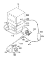
図1は本発明の実施形態に係る光断層画像化装置を用いた画像診断装置を示す外観図である。 FIG. 1 is an external view showing an image diagnostic apparatus using an optical tomographic imaging apparatus according to an embodiment of the present invention.
図1に示すように、この画像診断装置10は、主として内視鏡100、内視鏡プロセッサ200、光源装置300、光断層画像化装置としてのOCTプロセッサ400、及びモニタ装置である画像表示部500とから構成されている。なお、内視鏡プロセッサ200は、光源装置300を内蔵するように構成されていてもよい。
As shown in FIG. 1, the
内視鏡100は、手元操作部112と、この手元操作部112に連設される挿入部114とを備える。術者は手元操作部112を把持して操作し、挿入部114を被検者の体内に挿入することによって観察を行う。
The
手元操作部112には、鉗子挿入部138が設けられており、この鉗子挿入部138が挿入部114内に設けられている鉗子チャンネル(不図示)を介して先端部155の鉗子口156に連通されている。画像診断装置10では、光プローブとしてのOCTプローブ600を鉗子挿入部138から挿入することによって、OCTプローブ600を鉗子口156から導出する。OCTプローブ600は、鉗子挿入部138から挿入され、鉗子口156から導出される挿入部602と、術者がOCTプローブ600を操作するための操作部604、及びコネクタ410を介してOCTプロセッサ400と接続されるケーブル606から構成されている。
The
内視鏡100の先端部155には、観察光学系150、照明光学系152、及びCCD(不図示)が配設されている。
At the
観察光学系150は、被検体を図示しないCCDの受光面に結像させ、CCDは受光面上に結像された被検体像を各受光素子によって電気信号に変換する。この実施の形態のCCDは、3原色の赤(R)、緑(G)、青(B)のカラーフィルタが所定の配列(ベイヤー配列、ハニカム配列)で各画素ごとに配設されたカラーCCDである。
The observation
光源装置300は、可視光を図示しないライトガイド(内視鏡100のケーブル116に内挿している)に入射させる。ライトガイドの一端はLGコネクタ120を介して光源装置300に接続され、ライトガイドの他端は照明光学系152に対面している。光源装置300から発せられた光は、ライトガイドを経由して照明光学系152から出射され、観察光学系150の視野範囲を照明する。
The
内視鏡プロセッサ200には、内視鏡100のケーブル116を介してCCDから出力される画像信号が電気コネクタ110を介して入力される。このアナログの画像信号は、内視鏡プロセッサ200内においてデジタルの画像信号に変換され、画像表示部500の画面に表示するための必要な処理が施される。
An image signal output from the CCD via the
このように、内視鏡100で得られた観察画像のデータが内視鏡プロセッサ200に出力され、内視鏡プロセッサ200に接続された画像表示部500に画像が表示される。
In this manner, observation image data obtained by the
図2は図1のOCTプロセッサ400に接続されるOCTプローブの構成を示す図であり、図3は図2の多面体ミラーの詳細な構成を示す図である。また、図4ないし図6は図3の多面体ミラーの変形例の構成を示す図である。なお、図3では、光ファイバと多面体ミラーとの位置関係を説明するため、フレキシブルシャフトなどの構成部材の図示は省略している。
2 is a diagram showing a configuration of an OCT probe connected to the
図2に示すように、OCTプローブ600は、先端が閉塞された可撓性を有する細長で透明な略円筒状のシース620によって全体が覆われており、シース620内において、フレキシブルシャフト622の先端に固定されたn個(nは3以上の整数)の反射面(以下、光偏向面ともいう。)を有する多面体ミラー621と、n本の光ファイバ623(1)〜623(n)等が挿入配置されている。以下、説明を簡略化するため、n=6として説明する。
As shown in FIG. 2, the
多面体ミラー621は、図3に示すように、平面正6角形を底面621aとする正6角錐体において頭頂点側を所定の高さで切断した6角錐台の形状を有し、6角錐面より6個の光偏向面640(1)〜640(6)を有している。各光偏向面640(1)〜640(6)は、底面621aに対して例えば45度の傾斜で形成されている。その多面体ミラー621の底面621a側には、図2に示すように円筒状に突出した軸部621bが一体形成されており、その軸部621bが保持枠660によって回動自在に軸支されている。保持枠660は、シース620の内面に当接してプローブ長手軸に対して直交方向への変位が規制された状態で配置されており、これによって、多面体ミラー621がその中心軸(対称軸)をプローブ長手軸に略一致させた状態でシース620内に配置されると共に、プローブ長手軸周りに安定した状態で回転するようになっている。即ち、多面体ミラー621はプローブ長手軸を回転中心として前記6個の光偏向面640(1)〜640(6)を回転可能に配置した構成となっている。そして、多面体ミラー621は、プローブ長手軸を中心とする回転対称形状をなしている。
As shown in FIG. 3, the
一方、多面体ミラー621の頭頂点側には、回転トルクを伝達するフレキシブルシャフト622の先端がその長手軸を多面体ミラー621の中心軸に一致させた状態で連結されている。このフレキシブルシャフト622は基端側においてその長手軸を回転軸としたモータ625に一体的に連結されている。従って、モータ625を駆動することにより、その回転トルクがフレキシブルシャフト622を介して多面体ミラー621に伝達し、多面体ミラー621がプローブ長手軸周りに回転するようになっている。
On the other hand, the distal end of the
6本の光ファイバ623(1)〜623(6)(以下、6チャンネルファイバともいう。)は、先端面に集光手段としてのGRINレンズ624が設けられており、その先端部において回転体663に保持されると共に、フレキシブルシャフト622の長手軸、即ち、プローブ長手軸の周りに等角度間隔(60度)で環状に配置されている。そして、各光ファイバ623(1)〜623(6)の先端面が、多面体ミラー621の各光偏向面640(1)〜640(6)と対峙して配置されている。
The six optical fibers 623 (1) to 623 (6) (hereinafter also referred to as 6-channel fibers) are provided with a
回転体663は、保持枠660に回動可能に支持されており、保持枠660は、上記のようにシース620の内面に当接して6チャンネルファイバ623(1)〜623(6)の先端部分の位置を規制し、多面体ミラー621との6チャンネルファイバ623(1)〜623(6)との位置を規定の位置関係で保持している。
The rotating body 663 is rotatably supported by the holding
また、6チャンネルファイバ623(1)〜623(6)は、シース620と同様に可撓性を有する細長の略円筒状の内皮661により全体が覆われており、その内皮661の先端が回転体663に固着されている。従って、シース620内に内包される上記の多面体ミラー621、6チャンネルファイバ623(1)〜623(6)、フレキシブルシャフト622、保持枠660、回転体663、及び、内皮661は、シース内包部材としてプローブ長手軸方向に一体で移動するようになっており、6チャンネルファイバ623(1)〜623(6)、フレキシブルシャフト622、内皮661のうちの少なくとも1つが長手軸方向に進退駆動する進退移動手段としての進退駆動機構部631に接続されている。例えば、フレキシブルシャフト622がその基端に設置されたモータ625を介して進退駆動機構部631に接続されると共に内皮661の基端が進退駆動機構部631に接続されている。この進退駆動機構部631は、ボールネジ(不図示)等から構成され、モータ626の回転駆動力を進退駆動力に変換することで、シース内包部材をプローブ長手軸方向に進退駆動するように構成されている。また、回転体663と連結されている内皮661を回転させれば、回転体663が回転し、シース620内において6チャンネルファイバ623(1)〜623(6)のプローブ長手軸周りの位置を回転させることができるようになっている。この6チャンネルファイバ623(1)〜623(6)の回転は、進退駆動機構部631全体、または、内皮661をモータによって回転させるようにしてもよいし、一次的にフレキシブルシャフト622と連結させるクラッチ等の連結機構を設けて、その接続、切断を手動又は電動で切り替えられるようにして、多面体ミラー621と共に回転するようにしてもよい。単に手動で内皮661を回転させるようにしてもよい。
Further, the 6-channel fibers 623 (1) to 623 (6) are entirely covered with a thin and substantially
以上のごとく構成されたOCTプローブ600によれば、6チャンネルファイバ623(1)〜623(6)の各々にOCTプロセッサ400から測定光が与えられると、6チャンネルファイバ623(1)〜623(6)の先端部まで導波した測定光が、GRINレンズ624により集光作用を受けて出射され、6チャンネルファイバ623(1)〜623(6)の各々に対峙している多面体ミラー621の各光偏向面640(1)〜640(6)で反射して偏向され、各光偏向面640(1)〜640(6)で偏向された測定光が、プローブ長手軸方向に対して所定角度(例えば90度)傾斜したラジアル方向にシース620を透過して外部に出射されると共に、各々の測定光がプローブ長手軸周りの360度範囲にわたって等角度間隔(60度間隔)となる角度方向に出射される。また、各々の測定光が照射された測定対象からの戻り光が、その元となった測定光と同じ6チャンネルファイバ623(1)〜623(6)の各光ファイバに多面体ミラー621を介して取り込まれる。
According to the
また、6チャンネルファイバ623(1)〜623(6)は、シース620内では回転することなく固定されているので、光ロータリジョイントを必要とせず、モータ625によりフレキシブルシャフト622を介して多面体ミラー621を回転させて、各光偏向面640(1)〜640(6)を回転させることで、6チャンネルファイバ623(1)〜623(6)から出射された各々の測定光の出射方向が回転する。
Further, since the 6-channel fibers 623 (1) to 623 (6) are fixed without rotating in the
このとき、多面体ミラー621を60度(=360度×1/6)回転させることで、6チャンネルファイバ623(1)〜623(6)からの6本の測定光にて全周にわたるラジアル走査が可能となる。
At this time, by rotating the
つまり、3以上の整数nに対して、n個の反射面(光偏光面)を有する多面体ミラー621を「360度×1/n」回転させることで、nチャンネルファイバ623(1)〜623(n)からのn本の光にて360度の全周にわたるラジアル走査を高速に行うことが可能となる。
That is, the n-channel fibers 623 (1) to 623 () are rotated by rotating the
なお、上記OCTプローブ600の説明では、n=6を例に説明したがこれに限らず、例えば、多面体ミラー621の底面は、図4に示すように平面正8角形としてもよいし、図5に示すように平面正4角形としてもよいし、図6に示すように平面正3角形としてもよく、多面体ミラー621のn個の光偏向面640(1)〜640(n)に対応して、nチャンネルファイバ623(1)〜623(n)が配置されるように構成すればよい。
In the description of the
図7は図1のOCTプロセッサの構成を示すブロック図である。図7に示すように、OCTプロセッサ400は、光干渉断層(OCT:Optical Coherence Tomography)計測法による測定対象Sの光断層画像を取得するためのもので、測定のための光Laを射出する光源手段としてのOCT光源12と、OCT光源12から射出された光Laを最大nチャンネル分の光L1〜光Lnに分岐すると共に、分岐する数と分岐した光の供給先となるチャンネルを切り替える(光Laを分岐して供給する供給先となるチャンネルを切り替える)光スイッチ13と、nチャンネルの光L1〜光Lnを測定光と参照光に分波して干渉波を検波する第1ないし第nチャンネル干渉部14(1)〜14(n)より構成される干渉部14と、干渉部14の第1ないし第nチャンネル干渉部14(1)〜14(n)からの干渉波より干渉信号を生成する干渉信号生成部15と、干渉信号生成部15により生成された干渉信号に基づき測定対象Sの断層画像及び3次元ボリュームデータを生成し画像表示部500にこれらの画像を表示させる画像処理部17と、光スイッチ13に対して光スイッチ切替え制御信号を与え、光OCT光源12からの光Laを供給する供給先のチャンネルの切替えを指示する光スイッチ制御部18と、を備えて構成される。
FIG. 7 is a block diagram showing a configuration of the OCT processor of FIG. As shown in FIG. 7, the
以下、説明を簡略化するため、1からnをkにより代表させて説明する。図8は図7の干渉部14における第kチャンネル干渉部の構成を示すブロック図である。
Hereinafter, in order to simplify the description, 1 to n are represented by k. FIG. 8 is a block diagram showing a configuration of the k-th channel interference unit in the
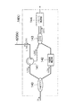
図8に示すように、干渉部14における第kチャンネル干渉部14(k)は、光スイッチ13により分岐された光Lkを測定光L1(k)と参照光L2(k)に分岐する分岐カプラ140と、測定光L1(k)をOCTプローブ600のkチャンネルファイバ623(k)に導波するサーキュレータ141と、参照光L2(k)を伝送させる光路長を補正する光路長補正部142と、OCTプローブ600のkチャンネルファイバ623(k)からのサーキュレータ141を介した測定対象Sからの戻り光L3(k)と光路長補正部142を介した参照光L2(k)とを干渉させる50:50カプラ143と、50:50カプラ143にて干渉した干渉光L4(k)をバランス検波し干渉信号生成部15に出力するバランス検波部144とを備えて構成される。
As shown in FIG. 8, the k-th channel interference unit 14 (k) in the
図9は図8の光路長補正部142の構成例を示す図である。参照光L2(k)の光路長補正部142は、各nチャネルのゼロパス位置を調整するため、第1ないし第nチャンネル干渉部14(1)〜14(n)のチャネル毎に設けられたn個の光路長(微調)調整手段であって、図9に示すように、2つのコリメートレンズ142a及び142bを用いて、コリメートレンズ142a及び142b間のコリメート光Lcに対して空間長を変えるように構成される。ここで、第1ないし第nチャンネル干渉部14(1)〜14(n)のいずれか1つの光路長を基準とすることで、光路長補正部142をn−1個とすることが可能である。なお、複屈折性を利用して光路長を変えるものでも構わない。
FIG. 9 is a diagram illustrating a configuration example of the optical path
続いてOCTプロセッサ400の基本的な動作についてラジアル走査時の動作を例に説明する。尚、光スイッチ13及び光スイッチ制御部18の作用については後述するものとし、光スイッチ13は、光スイッチ13の代わりに分岐カプラを設けた場合と同様に干渉部14の第1ないし第nチャンネル干渉部14(1)〜14(n)の全てにnチャンネル分の光L1〜光Lnを供給するものとして説明する。
Next, the basic operation of the
内視鏡100の鉗子チャンネルを挿通させて鉗子口156から導出させたOCTプローブ600をプローブ長手軸方向に沿って目的の測定部位の測定対象Sに密着又は近接させた状態に配置しているものとすると、測定時において、OCT光源12から射出された光Laは、光スイッチ13によりnチャンネル分の光L1〜光Lnに分岐され、各々、干渉部14の第1ないし第nチャンネル干渉部14(1)〜14(n)に供給される。そして、第1ないし第nチャンネル干渉部14(1)〜14(n)の各々において、測定光L1(1)〜L1(n)と参照光L2(1)〜L2(n)が生成され、測定光L1(1)〜L1(n)がOCTプローブ600のnチャンネルファイバ623(1)〜(n)に与えられる。これによって、測定光L1(1)〜L1(n)がnチャンネルファイバ623(1)〜(n)でOCTプローブ600の先端部に導波され、多面体ミラー621により各測定光L1(1)〜L1(n)がプローブ長手軸周りの所定角度間隔(360/n度)の角度方向に位置する測定対象Sに照射される。そして、各測定光L1(1)〜L1(n)に対する測定対象Sからの戻り光L3(1)〜L3(n)が、それらの元となった測定光L1(1)〜L1(n)と同じ光ファイバ623(1)〜(n)により取り込まれて導波され、干渉部14の第1ないし第nチャンネル干渉部14(1)〜14(n)に取り込まれる。
The
第1ないし第nチャンネル干渉部14(1)〜14(n)に戻り光L3(1)〜L3(n)が取り込まれと、戻り光L3(1)〜L3(n)は、参照光L2(1)〜L2(n)と干渉して干渉光L4(1)〜L4(n)が生成され、各々、第1ないし第nチャンネル干渉部14(1)〜14(n)のバランス検波部144により検波される。そして、検波された信号に基づいて干渉信号生成部15により干渉信号が生成される。
When the return lights L3 (1) to L3 (n) are taken into the first to n-th channel interference units 14 (1) to 14 (n), the return lights L3 (1) to L3 (n) are converted to the reference light L2. Interference light L4 (1) to L4 (n) is generated by interfering with (1) to L2 (n), and balance detectors of the first to nth channel interference units 14 (1) to 14 (n), respectively. 144 is detected. Then, an interference
干渉信号生成部15は、OCT光源12からの波長掃引の周期に同期して出力される波長掃引同期信号をトリガとして、干渉信号をA/D変換する。この結果、各第1ないし第nチャンネル干渉部14(1)〜14(n)からの1回の波長掃引に相当するデータが、OCTプローブ600における各測定光L(1)〜L1(n)の出射方向の角度(プローブ長手軸周りの角度)に対するデジタル化された干渉信号となる。
The interference
また、干渉信号生成部15は、第1ないし第nチャンネル干渉部14(1)〜14(n)からのデジタル化された干渉信号に対して、高速フーリエ変換(FFT)処理を実行して周波数分解し、測定対象Sの深度方向の反射強度データとし、対数変換を行うことによって断層画像を表示するためのデータを生成する。
In addition, the interference
以上の処理は、ラジアル走査時において、OCTプローブ600の多面体ミラー621をモータ625により回転させながら連続的に行われ、多面体ミラー621の回転によって、OCTプローブ600(多面体ミラー621)から出射される各測定光L1(1)〜L1(n)の出射方向の角度を変化させ、各角度での干渉信号が順次に生成される。そして、多面体ミラー621が360/n度分回転すると、プローブ長手軸周りの360度にわたる全角度範囲の干渉信号が生成され、1フレーム分の断層画像、OCTプローブ600の全周にわたる断層画像を表示するための1ラジアル走査ラインデータ(反射強度データ)が生成される。
The above processing is performed continuously while rotating the
画像処理部17は、干渉信号生成部15からの1ラジアル走査ラインデータである反射強度データを読み込み、輝度調整、コントラスト調整、ガンマ補正、表示サイズにあわせたリサンプル、走査方法に合わせての座標変換等を行い、1フレームの断層画像を生成し、画像表示部500に断層画像を表示させる。
The
次に、OCTプローブ600への測定光の供給に関して説明する。
Next, supply of measurement light to the
例えば、管径の大きな管腔部位を測定する場合、OCTプローブ600に対して測定対象の表面が略平坦と見なせる状態となるため、測定対象がシース620の周面の一部の範囲のみに近接する。このとき、OCTプローブ600のnチャンネルファイバ623(1)〜(n)の全て(全てのチャンネル)に対してOCTプロセッサ400から測定光L1(1)〜L1(n)を与えて断層画像を生成したとすると、図10(A)のような断層画像が得られる。これによれば、シース620を示す断層画像がプローブ長手軸周りの360度の全角度範囲に表示されているが、シース620の断層画像は不要なものである。
For example, when measuring a luminal region having a large tube diameter, the surface of the measurement object can be considered to be substantially flat with respect to the
一方、測定対象Sの断層画像は有益なものであるが、その測定対象Sの断層画像が得られる範囲は、例えば同図のように180度の角度範囲よりも小さくなり、同図の角度範囲θとなる。 On the other hand, the tomographic image of the measuring object S is useful, but the range in which the tomographic image of the measuring object S is obtained is smaller than the angular range of 180 degrees, for example, as shown in FIG. θ.
そこで、以下のように、OCTプローブ600のnチャンネルファイバ623(1)〜(n)のうち、角度範囲θの断層画像の取得に関係する光ファイバのみに測定光を与え、それ以外の光ファイバには測定光を与えないようにすることによってOCTプローブ600に与える測定光の本数を減らして光量の増加を図るようにしている。尚、OCTプローブ600から測定光を与えるOCTプローブ600の光ファイバのチャンネル及びそれに対応したOCTプローブ600における干渉部14等のチャンネルを有効チャンネルといい、同様に測定光を与えないチャンネルを無効チャンネルというものとする。
Therefore, as described below, the measurement light is given only to the optical fiber related to the acquisition of the tomographic image in the angle range θ among the n-channel fibers 623 (1) to (n) of the
図7に示した光スイッチ13は、有効チャンネルとするチャンネルのみにOCT光源12からの光Laを分岐して供給するものであり、光スイッチ制御部18からの制御信号に従ってOCT光源12からの光Laを分岐して与えるチャンネルを切り替えるようになっている。これによって、OCT光源12からの光Laを全てのチャンネルに分岐する場合に比べて、有効チャンネルの測定光の光量を増加させることができ、画質の良い断層画像を生成することができる。
The
これらの光スイッチ13及び光スイッチ制御部18の作用について有効チャンネルを設定して本スキャンを開始するまでの手順を示した図11のフローチャートに従って説明する。
The operation of the
まず、本スキャンの前にプレスキャンを行う(ステップS10)。プレスキャンは、OCTプローブ600のnチャンネルファイバ623(1)〜(n)の全てを有効チャンネルとして測定光を与えると共に、多面体ミラー621を回転させて、プローブ長手軸周りの360度の全角度範囲の断層画像、即ち、OCTプローブ600の全周にわたる断層画像を取得する処理である。このとき、光スイッチ制御部18からの制御信号により、光スイッチ13は、OCT光源12からの光Laをn個の全てのチャンネルに分岐して光L1〜光Lnを第1ないし第nチャンネル干渉部14(1)〜14(n)に与える。
First, a pre-scan is performed before the main scan (step S10). The pre-scan provides measurement light using all of the n-channel fibers 623 (1) to (n) of the
これによって、第1ないし第nチャンネル干渉部14(1)〜14(n)からOCTプローブ600のnチャンネルファイバ623(1)〜(n)の全てに測定光L1(1)〜L(n)が与えられて、それらの測定光L1(1)〜L(n)がOCTプローブ600から出射される。そして、多面体ミラー621が360/n度回転すると、プローブ長手軸周りの360度の全角度範囲の断層画像が生成され、画像表示部500に表示される。
Accordingly, the measurement lights L1 (1) to L (n) are transmitted from the first to n-th channel interference units 14 (1) to 14 (n) to all the n-channel fibers 623 (1) to (n) of the
次に、測定範囲を決定する。即ち、測定光を出射する方向の角度範囲を決定する(ステップS12)。この測定範囲の決定は、手動と自動のいずれでも行うことができる。 Next, the measurement range is determined. That is, the angle range in the direction in which the measurement light is emitted is determined (step S12). The measurement range can be determined either manually or automatically.
手動で行う場合には、画像表示部500に表示されたプレスキャンの断層画像を術者が確認して所定の入力手段により測定範囲を指定して決定する。例えば、図10(A)の場合、角度範囲θを含むように指定して決定する。
When performing manually, an operator confirms the pre-scan tomographic image displayed on the
自動で行う場合には、例えば、上記のプレスキャン時に干渉信号生成部15において生成された干渉信号に基づいて測定対象Sが存在する範囲を検出して測定範囲を決定する。具体的には、測定光の出射方向の角度毎に、干渉信号の強度(絶対値)、又は、その積分値を求める。そして、その強度又は積分値が所定の閾値よりも大きくなる角度範囲を測定範囲として決定する。断層画像の画素値によって同様の決定を行うようにしてもよい。図10(A)の例では、角度範囲P1、P2、P6が測定範囲を含む範囲となる。
In the case of performing automatically, for example, the measurement range is determined by detecting the range in which the measurement target S exists based on the interference signal generated in the interference
次に、OCTプローブ600のnチャンネルファイバ623(1)〜623(n)をシース620内で回転させる(ステップS14)。これによって、測定範囲と、nチャンネルファイバ623(1)〜623(n)との位置関係の適正化を図る。例えば、測定範囲が狭い場合に1つのチャンネルのみを有効チャンネルとすれば、その測定範囲の測定が可能であるようなときでも、光ファイバと測定範囲の位置関係が悪いために2つのチャンネルを有効チャンネルにしなければならないという場合が生じる。そこで、モータを使用して自動で図2の回転体663(内皮661)を回転させ、又は、手動で回転させ、nチャンネルファイバ623(1)〜623(n)と測定範囲との位置関係が適正となるようにし、測定光の本数をできるだけ減らす。
Next, the n-channel fibers 623 (1) to 623 (n) of the
ここで、ステップS12において、角度毎に求めた干渉信号の強度又は積分値の中心値(重心)を求め、その位置を基準に最適となる(有効チャンネルを最も減らすことができる)角度位置にnチャンネルファイバ623(1)〜623(n)を配置するようにしてもよい。 Here, in step S12, the central value (center of gravity) of the interference signal intensity or integral value obtained for each angle is obtained, and the optimum angular position (where the effective channel can be reduced most) is set to the angular position n. Channel fibers 623 (1) to 623 (n) may be arranged.
次に、有効チャンネルを決定する(ステップS16)。この処理は、ステップS12において決定した測定範囲(角度範囲)を測定光の出射方向の角度範囲として含むチャンネルを有効チャンネルとして決定する処理である。即ち、OCTプローブ600のnチャンネルファイバ623(1)〜(n)のうち、ステップS12において決定した測定範囲を測定するために必要な光ファイバを決定する。
Next, an effective channel is determined (step S16). This process is a process of determining, as an effective channel, a channel that includes the measurement range (angle range) determined in step S12 as the angle range in the measurement light emission direction. That is, an optical fiber necessary for measuring the measurement range determined in step S12 is determined among the n-channel fibers 623 (1) to (n) of the
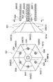
そして、本スキャンを開始する(ステップS16)。このとき、光スイッチ制御部18は、光スイッチ13を制御して有効チャンネルのみにOCT光源12からの光Laを分岐して供給させ、多面体ミラー621を回転させる。例えば、プレスキャン時においては、OCTプローブ600のnチャンネルファイバ623(1)〜(n)の全てに測定光が与えられて、図12(A)(n=6の場合を示す)のように多面体ミラー621の全ての光偏向面640(1)〜640(6)に測定光が導波されている(黒丸Sが導波箇所を示す)。一方、本スキャンでは、OCTプローブ600のnチャンネルファイバ623(1)〜(n)のうちの一部の光ファイバのみに測定光が与えられ、同図(B)のように多面体ミラー621の一部の光偏向面のみ測定光が導波されている(黒丸Sが導波箇所を示し、3箇所に減っている)。
Then, the main scan is started (step S16). At this time, the optical
このようにして、OCTプローブ600からの有効チャンネルのみによる測定光の出射と戻り光の取込みが行われると共に、ラジアル走査が行われて断層画像が生成され、画像表示部500に表示される。例えばプレスキャンにおいて図10(A)のような断層画像が得られた場合にステップS12において角度範囲P1、P2、P6を測定範囲として決定した場合、図10(B)のような断層画像が表示されることになる。
In this manner, the measurement light is emitted from the
これにより、有効チャンネルのみに測定光が供給されるようになり、全てのチャンネルに測定光を供給する場合よりも測定光の光量が増加し、画質の良い断層画像が生成される。 As a result, the measurement light is supplied only to the effective channels, and the amount of the measurement light is increased as compared with the case where the measurement light is supplied to all the channels, and a tomographic image with good image quality is generated.
また、本スキャンでは、OCTプローブ600のシース620に対して内部の多面体ミラー621、nチャンネルファイバ623(1)〜623(n)等の構成部材が進退駆動機構部631によりプローブ長手軸方向に移動し、多面体ミラー621の回転によるラジアル走査と同時又は交互にリニア走査が行われ、3次元ボリュームデータが取得されるようになっている。
In this scan, components such as an
以上の実施の形態では、OCTプローブ600における多面体ミラーの光偏向面の数と、光ファイバの数とが一致している態様を示したが、本発明は、それらの数が一致していなくても適用でき、特にシース620内での光ファイバのプローブ長手周りの位置を調整して、光ファイバと測定範囲(測定対象)との位置関係を調整することができるため光ファイバが1本であっても有効である。
In the above embodiment, the aspect in which the number of light deflecting surfaces of the polyhedral mirror in the
また、必ずしも測定対象Sが存在する範囲の全域を測定範囲とする必要はなく、例えば、予め決まった数(1つ又は所定数)のチャンネル(光ファイバ)を有効チャンネルとして、その有効チャンネルにより測定可能な範囲を測定範囲としてもよい。このとき、測定対象Sが存在する範囲の一部が測定範囲外となる場合があるが、できるだけ測定対象Sが存在する範囲の中央(例えば、各角度の干渉信号の積分値が所定の閾値を超える範囲の中央(重心))が、有効チャンネルの測定範囲での中央となるように、OCTプローブ600内においてプローブ長手軸周りの光ファイバの回転位置を調整して本スキャンを行うようにすれば好適である。また、1つのチャンネルのみを有効チャンネルとする場合には、OCTプロセッサ400の構成も簡素化できる。即ち、図7のOCTプロセッサ400の構成において、nチャンネル分の第1ないし第nチャンネル干渉部14(1)〜14(n)は不要であり、図8に示した1チャネル分の干渉部14を設け、OCT光源12からの光を光スイッチ13を介すことなく、その干渉部14に入射させるようにすればよい。そして、光スイッチ13を、干渉部14(図8のサーキュレータ141)とOCTプローブ600との間に配置し、その光スイッチ13によって、OCTプローブ600のいずれか1つのチャンネルの光ファイバと干渉部14とを光学的に接続すると共に、接続するチャンネルを切り替えるようにすればよい。光スイッチ13による接続先の切り替えは、上記実施の形態と同様に光スイッチ制御部18によって行われるものとすればよい。
In addition, it is not always necessary to set the entire measurement range where the measurement target S exists as a measurement range. For example, a predetermined number (one or a predetermined number) of channels (optical fibers) are used as effective channels, and measurement is performed using the effective channels. The possible range may be the measurement range. At this time, a part of the range where the measurement target S exists may be outside the measurement range, but the center of the range where the measurement target S exists as much as possible (for example, the integrated value of the interference signal at each angle has a predetermined threshold value). If the rotational position of the optical fiber around the longitudinal axis of the probe is adjusted in the
10…画像診断装置、12…OCT光源、13…光スイッチ、14…干渉部、15…干渉信号生成部、17…画像処理部、18…光スイッチ制御部、100…内視鏡、114…装入部、156…鉗子口、200…内視鏡プロセッサ、400…OCTプロセッサ、500…画像表示部、600…OCTプローブ、620…シース、621…多面体ミラー、622…フレキシブルシャフト、623…光ファイバ、624…GRINレンズ、625,626…モータ、640…光偏向面、663…回転体
DESCRIPTION OF
Claims (5)
細長な筒状のシースと、該シース内に配置された複数の導光手段と、該導光手段から出射された測定光を前記シースの側面に向けて偏向する複数の光偏向面を有する多面体ミラーとを備え、前記シース内において前記導光手段が前記シースの長手軸周りに回動可能に配置された光プローブと、
前記複数の導光手段の全てに前記光源からの測定光を与えて前記シースの周方向に沿った領域の少なくとも干渉信号を取得するプレスキャン手段と、
前記プレスキャン手段により取得した干渉信号又は断層画像に基づいて前記シースの周方向に沿った領域のうち、測定を行う領域を測定領域として決定する測定領域決定手段と、
前記測定領域決定手段により決定された測定領域に応じて、前記シース内における前記導光手段の前記長手軸周りの位置を調整する導光手段位置調整手段と、
前記測定領域決定手段により決定された測定領域の断層画像の取得に関係する導光手段のみに前記光源からの測定光を与えて前記測定領域のみの断層画像を取得する本スキャン手段と、
を備えたことを特徴とする光断層画像化装置。 The light emitted from the light source is divided into measurement light and reference light, and the measurement object is irradiated with the measurement light, the reflected light from the measurement object and the reference light are combined, and the reflected light and the reference An optical tomographic imaging apparatus that detects interference light when light is combined as an interference signal, and acquires a tomographic image of the measurement object using the interference signal,
Has a Do tubular sheath elongated, and multiple light guiding means disposed within the sheath, a plurality of light deflection faces for deflecting towards the measurement light emitted from the light guide means to the side of the sheath An optical probe provided with a polyhedral mirror, wherein the light guide means is arranged to be rotatable around the longitudinal axis of the sheath in the sheath;
A prescanning means for obtaining at least an interference signal region along the circumferential direction of the sheath gives the measurement light from the light source to all of the light guide means of the front Kifuku number,
A measurement area determination means for determining a measurement area as a measurement area among areas along the circumferential direction of the sheath based on an interference signal or a tomographic image acquired by the prescan means;
Light guide means position adjusting means for adjusting the position of the light guide means around the longitudinal axis in the sheath according to the measurement area determined by the measurement area determining means;
A main scanning unit that applies the measurement light from the light source only to the light guide unit related to the acquisition of the tomographic image of the measurement region determined by the measurement region determination unit, and acquires the tomographic image of the measurement region only;
An optical tomographic imaging apparatus comprising:
細長な筒状のシースと、該シース内に配置された複数の導光手段と、該導光手段から出射された測定光を前記シースの側面に向けて偏向する複数の光偏向面を有する多面体ミラーとを備え、前記シース内において前記導光手段が前記シースの長手軸周りに回動可能に配置された光プローブを備え、さらに、プレスキャン手段と、測定領域決定手段と、導光手段位置調整手段と、本スキャン手段とを備えた光断層画像化装置の作動方法であって、
前記プレスキャン手段が、前記複数の導光手段の全てに前記光源からの測定光を与えて前記シースの周方向に沿った領域の少なくとも干渉信号を取得するプレスキャン工程と、
前記測定領域決定手段が、前記プレスキャン手段により取得した干渉信号又は断層画像に基づいて前記シースの周方向に沿った領域のうち、測定を行う領域を測定領域として決定する測定領域決定工程と、
前記導光手段位置調整手段が、前記測定領域決定手段により決定された測定領域に応じて、前記シース内における前記導光手段の前記長手軸周りの位置を調整する導光手段位置調整工程と、
前記本スキャン手段が、前記測定領域決定手段により決定された測定領域の断層画像の取得に関係する導光手段のみに前記光源からの測定光を与えて前記測定領域のみの断層画像を取得する本スキャン工程と、
を備えたことを特徴とする光断層画像化装置の作動方法。 The light emitted from the light source is divided into measurement light and reference light, and the measurement object is irradiated with the measurement light, the reflected light from the measurement object and the reference light are combined, and the reflected light and the reference An optical tomographic imaging apparatus that detects interference light when light is combined as an interference signal, and acquires a tomographic image of the measurement object using the interference signal,
A polyhedron having an elongated cylindrical sheath, a plurality of light guides disposed in the sheath, and a plurality of light deflection surfaces for deflecting measurement light emitted from the light guides toward the side surface of the sheath And a light probe disposed in the sheath so as to be rotatable around the longitudinal axis of the sheath , and further includes a pre-scanning means, a measurement region determining means, and a light guiding means position. An operation method of an optical tomographic imaging apparatus including an adjusting unit and a main scanning unit ,
It said prescanning means includes a prescan step of obtaining at least an interference signal region along the circumferential direction of the sheath gives the measurement light from the light source to all of the plurality of light guide means,
The measurement region determining means, in the region along the circumferential direction of the sheath, based on the obtained interference signal or the tomographic image by the prescanning means, and the measurement area determining step of determining a region to be measured as a measurement region,
A light guide means position adjustment step in which the light guide means position adjustment means adjusts the position of the light guide means around the longitudinal axis in the sheath according to the measurement region determined by the measurement region determination means ;
A book in which the main scanning unit applies the measurement light from the light source only to the light guide unit related to the acquisition of the tomographic image of the measurement region determined by the measurement region determination unit and acquires the tomographic image of only the measurement region. Scanning process;
A method for operating an optical tomographic imaging apparatus comprising:
Priority Applications (1)
| Application Number | Priority Date | Filing Date | Title |
|---|---|---|---|
| JP2010194951A JP5663241B2 (en) | 2010-08-31 | 2010-08-31 | Optical tomographic imaging apparatus and operating method thereof |
Applications Claiming Priority (1)
| Application Number | Priority Date | Filing Date | Title |
|---|---|---|---|
| JP2010194951A JP5663241B2 (en) | 2010-08-31 | 2010-08-31 | Optical tomographic imaging apparatus and operating method thereof |
Publications (3)
| Publication Number | Publication Date |
|---|---|
| JP2012052883A JP2012052883A (en) | 2012-03-15 |
| JP2012052883A5 JP2012052883A5 (en) | 2013-09-05 |
| JP5663241B2 true JP5663241B2 (en) | 2015-02-04 |
Family
ID=45906367
Family Applications (1)
| Application Number | Title | Priority Date | Filing Date |
|---|---|---|---|
| JP2010194951A Active JP5663241B2 (en) | 2010-08-31 | 2010-08-31 | Optical tomographic imaging apparatus and operating method thereof |
Country Status (1)
| Country | Link |
|---|---|
| JP (1) | JP5663241B2 (en) |
Families Citing this family (1)
| Publication number | Priority date | Publication date | Assignee | Title |
|---|---|---|---|---|
| JP6803887B2 (en) * | 2018-10-10 | 2020-12-23 | 株式会社吉田製作所 | Optical interference tomographic image generator |
Family Cites Families (11)
| Publication number | Priority date | Publication date | Assignee | Title |
|---|---|---|---|---|
| JP4960336B2 (en) * | 2001-10-31 | 2012-06-27 | オリンパス株式会社 | Optical scanning observation device |
| JP2002221486A (en) * | 2001-11-30 | 2002-08-09 | Olympus Optical Co Ltd | Optical tomograph imaging system |
| DE202005011177U1 (en) * | 2005-07-15 | 2006-11-23 | J & M Analytische Mess- Und Regeltechnik Gmbh | Device for analysis, in particular photometric or spectrophotometric analysis |
| JP4864662B2 (en) * | 2006-11-24 | 2012-02-01 | 富士フイルム株式会社 | Optical probe and optical therapy diagnostic system using the same |
| JP5022845B2 (en) * | 2007-09-19 | 2012-09-12 | 富士フイルム株式会社 | Optical tomographic imaging system |
| JP2009183459A (en) * | 2008-02-06 | 2009-08-20 | Olympus Corp | Spectroscopic analyzer for blood vessel |
| JP2009232960A (en) * | 2008-03-26 | 2009-10-15 | Fujifilm Corp | Optical probe device |
| JP2010043994A (en) * | 2008-08-15 | 2010-02-25 | Fujifilm Corp | Optical probe and three-dimensional image acquiring apparatus |
| JP5162431B2 (en) * | 2008-12-10 | 2013-03-13 | 富士フイルム株式会社 | Optical three-dimensional structure image device |
| JP5339934B2 (en) * | 2009-01-22 | 2013-11-13 | キヤノン株式会社 | Optical tomographic imaging apparatus and optical tomographic imaging method |
| JP5236573B2 (en) * | 2009-05-14 | 2013-07-17 | 富士フイルム株式会社 | Optical structure measuring device and optical probe thereof |
-
2010
- 2010-08-31 JP JP2010194951A patent/JP5663241B2/en active Active
Also Published As
| Publication number | Publication date |
|---|---|
| JP2012052883A (en) | 2012-03-15 |
Similar Documents
| Publication | Publication Date | Title |
|---|---|---|
| JP5236573B2 (en) | Optical structure measuring device and optical probe thereof | |
| JP4577504B2 (en) | Diagnostic imaging equipment | |
| JP4789922B2 (en) | Forward scanning imaging fiber optic detector | |
| US20050234347A1 (en) | Puncture-type endoscopic probe | |
| US7627208B2 (en) | Optical probe and optical tomography apparatus | |
| US11835707B2 (en) | Scanning optical imaging device | |
| JP5259374B2 (en) | Optical structure observation apparatus and structure information processing method thereof | |
| JP2001046321A (en) | Endoscope device | |
| JP2008228810A (en) | Endoscope observation device, observation device and endoscope observation method | |
| CN102256530A (en) | Optical probe and optical observation device | |
| JP5663240B2 (en) | Optical tomographic imaging apparatus and operating method thereof | |
| US20100041948A1 (en) | Optical probe and three-dimensional image acquisition apparatus | |
| JP2010179042A (en) | Optical structure observation apparatus, structural information processing method therefor, and endoscope system with optical structure observation apparatus | |
| JP2008289850A (en) | Optical probe and optical tomography apparatus | |
| US11224336B2 (en) | Rotational extender and/or repeater for rotating fiber based optical imaging systems, and methods and storage mediums for use therewith | |
| JP2022523720A (en) | Imaging reconstruction using real-time signal of rotational position from encoder near distal end | |
| JP5635868B2 (en) | Optical tomographic imaging system | |
| JP5663241B2 (en) | Optical tomographic imaging apparatus and operating method thereof | |
| JP2000126188A (en) | Optical tomographic imaging apparatus | |
| JPH06154228A (en) | Optical tomographic imaging | |
| JP2008142454A (en) | Medical diagnostic probe and medical diagnostic system | |
| JP5657941B2 (en) | Optical tomographic imaging apparatus and operating method thereof | |
| WO2020163449A1 (en) | Endoscope observation window cleaning | |
| JP2012050609A (en) | Image diagnostic apparatus and image diagnostic method | |
| JP2002221486A (en) | Optical tomograph imaging system |
Legal Events
| Date | Code | Title | Description |
|---|---|---|---|
| A711 | Notification of change in applicant |
Free format text: JAPANESE INTERMEDIATE CODE: A711 Effective date: 20130528 |
|
| A621 | Written request for application examination |
Free format text: JAPANESE INTERMEDIATE CODE: A621 Effective date: 20130718 |
|
| A521 | Request for written amendment filed |
Free format text: JAPANESE INTERMEDIATE CODE: A523 Effective date: 20130723 |
|
| A977 | Report on retrieval |
Free format text: JAPANESE INTERMEDIATE CODE: A971007 Effective date: 20140129 |
|
| A131 | Notification of reasons for refusal |
Free format text: JAPANESE INTERMEDIATE CODE: A131 Effective date: 20140131 |
|
| A521 | Request for written amendment filed |
Free format text: JAPANESE INTERMEDIATE CODE: A523 Effective date: 20140331 |
|
| A131 | Notification of reasons for refusal |
Free format text: JAPANESE INTERMEDIATE CODE: A131 Effective date: 20140710 |
|
| A521 | Request for written amendment filed |
Free format text: JAPANESE INTERMEDIATE CODE: A523 Effective date: 20140821 |
|
| TRDD | Decision of grant or rejection written | ||
| A01 | Written decision to grant a patent or to grant a registration (utility model) |
Free format text: JAPANESE INTERMEDIATE CODE: A01 Effective date: 20141202 |
|
| A61 | First payment of annual fees (during grant procedure) |
Free format text: JAPANESE INTERMEDIATE CODE: A61 Effective date: 20141208 |
|
| R150 | Certificate of patent or registration of utility model |
Ref document number: 5663241 Country of ref document: JP Free format text: JAPANESE INTERMEDIATE CODE: R150 |
|
| R250 | Receipt of annual fees |
Free format text: JAPANESE INTERMEDIATE CODE: R250 |
|
| R250 | Receipt of annual fees |
Free format text: JAPANESE INTERMEDIATE CODE: R250 |
|
| R250 | Receipt of annual fees |
Free format text: JAPANESE INTERMEDIATE CODE: R250 |
|
| R250 | Receipt of annual fees |
Free format text: JAPANESE INTERMEDIATE CODE: R250 |
|
| R250 | Receipt of annual fees |
Free format text: JAPANESE INTERMEDIATE CODE: R250 |
|
| R250 | Receipt of annual fees |
Free format text: JAPANESE INTERMEDIATE CODE: R250 |
|
| R250 | Receipt of annual fees |
Free format text: JAPANESE INTERMEDIATE CODE: R250 |