JP5662913B2 - Wireless communication system and base station - Google Patents
Wireless communication system and base station Download PDFInfo
- Publication number
- JP5662913B2 JP5662913B2 JP2011203534A JP2011203534A JP5662913B2 JP 5662913 B2 JP5662913 B2 JP 5662913B2 JP 2011203534 A JP2011203534 A JP 2011203534A JP 2011203534 A JP2011203534 A JP 2011203534A JP 5662913 B2 JP5662913 B2 JP 5662913B2
- Authority
- JP
- Japan
- Prior art keywords
- base station
- terminal
- interference
- multicast
- information
- Prior art date
- Legal status (The legal status is an assumption and is not a legal conclusion. Google has not performed a legal analysis and makes no representation as to the accuracy of the status listed.)
- Expired - Fee Related
Links
- 238000004891 communication Methods 0.000 title claims description 121
- 238000012545 processing Methods 0.000 claims description 106
- 230000005540 biological transmission Effects 0.000 claims description 88
- 238000000034 method Methods 0.000 claims description 72
- 230000008569 process Effects 0.000 claims description 46
- 238000005259 measurement Methods 0.000 claims description 45
- 230000002452 interceptive effect Effects 0.000 claims description 24
- 238000013468 resource allocation Methods 0.000 description 40
- 230000006870 function Effects 0.000 description 30
- 208000037918 transfusion-transmitted disease Diseases 0.000 description 23
- 238000010586 diagram Methods 0.000 description 13
- 230000004044 response Effects 0.000 description 8
- 230000000694 effects Effects 0.000 description 7
- 238000011144 upstream manufacturing Methods 0.000 description 7
- 101150096038 PTH1R gene Proteins 0.000 description 5
- 238000001514 detection method Methods 0.000 description 5
- 238000007726 management method Methods 0.000 description 5
- 238000013459 approach Methods 0.000 description 4
- 230000007423 decrease Effects 0.000 description 3
- 230000007774 longterm Effects 0.000 description 3
- 238000005070 sampling Methods 0.000 description 3
- 230000002411 adverse Effects 0.000 description 2
- 230000001413 cellular effect Effects 0.000 description 2
- 238000013506 data mapping Methods 0.000 description 2
- 238000013461 design Methods 0.000 description 2
- 238000005516 engineering process Methods 0.000 description 2
- 239000000284 extract Substances 0.000 description 2
- 238000012423 maintenance Methods 0.000 description 2
- 238000012544 monitoring process Methods 0.000 description 2
- 230000000737 periodic effect Effects 0.000 description 2
- 238000010248 power generation Methods 0.000 description 2
- 238000002360 preparation method Methods 0.000 description 2
- 230000001737 promoting effect Effects 0.000 description 2
- 230000003313 weakening effect Effects 0.000 description 2
- 238000012935 Averaging Methods 0.000 description 1
- 230000008859 change Effects 0.000 description 1
- 238000006243 chemical reaction Methods 0.000 description 1
- 239000012141 concentrate Substances 0.000 description 1
- 125000004122 cyclic group Chemical group 0.000 description 1
- 238000011161 development Methods 0.000 description 1
- 230000005684 electric field Effects 0.000 description 1
- 238000000605 extraction Methods 0.000 description 1
- 230000007274 generation of a signal involved in cell-cell signaling Effects 0.000 description 1
- 230000006872 improvement Effects 0.000 description 1
- 238000004519 manufacturing process Methods 0.000 description 1
- 230000009467 reduction Effects 0.000 description 1
- 239000007787 solid Substances 0.000 description 1
- 238000003860 storage Methods 0.000 description 1
- 230000001360 synchronised effect Effects 0.000 description 1
- 238000012546 transfer Methods 0.000 description 1
- 230000001960 triggered effect Effects 0.000 description 1
Images


Classifications
-
- H—ELECTRICITY
- H04—ELECTRIC COMMUNICATION TECHNIQUE
- H04W—WIRELESS COMMUNICATION NETWORKS
- H04W36/00—Hand-off or reselection arrangements
- H04W36/16—Performing reselection for specific purposes
- H04W36/20—Performing reselection for specific purposes for optimising the interference level
-
- H—ELECTRICITY
- H04—ELECTRIC COMMUNICATION TECHNIQUE
- H04W—WIRELESS COMMUNICATION NETWORKS
- H04W36/00—Hand-off or reselection arrangements
- H04W36/08—Reselecting an access point
Description
本発明は、無線通信システム及び基地局に係り、特に出力が大きい基地局と出力が小さい基地局とが混在するヘテロジニアスネットワークにおいて与干渉端末のハンドオーバ処理を促進する無線通信システム及び基地局に関する。 The present invention relates to a radio communication system and a base station, and more particularly to a radio communication system and a base station that facilitate handover processing of an interfering terminal in a heterogeneous network in which a base station having a high output and a base station having a low output are mixed.
本技術分野の背景技術として、OFDMA(Orthogonal Frequency Division Multiple Access)−MIMO(Multiple Input Multiple Output)技術を適用したセルラシステムであるLTE(Long Term Evolution)があり、既に一部の国でサービスインを迎えている。
近年のセルラシステムは、従来主流であった大型かつ大出力のマクロ基地局だけでなく、より小型かつ小出力のピコ基地局、フェムト基地局が増加し、マクロ基地局のカバレッジホールを埋めたり、ホットスポットと呼ばれるデータトラフィックが局所的に高い地域に配置して、マクロ基地局に接続する端末を小型基地局側へシフトすること、すなわちトラフィックオフロード用途として使われたりしている。
大型基地局と小型基地局が混在するネットワークは、ヘテロジニアスネットワークと呼ばれる。ヘテロジニアスネットワーク特有の課題として、下りのセルエッジと上りのセルエッジが一致しないことがある。一般的に、大型基地局と小型基地局の間に形成されるセルエッジは、下りセルエッジに対して上りセルエッジは大型基地局寄りに位置する。LTEでは端末が下り受信電力が高い基地局へ接続するため、大型基地局に接続する下りセルエッジ端末は、上りセルエッジよりも小型基地局に寄った位置で上り信号を送信することとなる。その結果、当該端末近傍に位置する小型基地局に対して大きな受信電力の上り干渉信号を送信することとなる。
Background art of this technical field is OFDMA (Orthogonal Frequency Division Multiple Access) -LTE (Long Term Evolution), which is a cellular system to which MIMO (Multiple Input Multiple Output) technology is applied. I am greeted.
In recent cellular systems, not only large and large output macro base stations that have been mainstream in the past, but also smaller and smaller output pico base stations and femto base stations have increased, filling the coverage holes of macro base stations, It is used in an area where data traffic called a hot spot is locally located in a high area and a terminal connected to a macro base station is shifted to a small base station, that is, for traffic offload.
A network in which large base stations and small base stations are mixed is called a heterogeneous network. A problem specific to heterogeneous networks is that the downlink cell edge and the uplink cell edge do not match. In general, the cell edge formed between the large base station and the small base station is located closer to the large base station than the downstream cell edge. In LTE, since a terminal connects to a base station having high downlink reception power, a downlink cell edge terminal connected to a large base station transmits an uplink signal at a position closer to the small base station than to the uplink cell edge. As a result, an uplink interference signal with a large received power is transmitted to a small base station located in the vicinity of the terminal.
この問題を解決するための方法の一つを、[特許文献1]が開示している。同特許文献では、概略、小型基地局において、小型基地局に対して大きな干渉を及ぼしうる大型基地局接続の端末を検出し、検出情報を大型基地局へ通知し、小型基地局へのハンドオーバを促す。
LTEにおけるハンドオーバ関連処理は、例えば[非特許文献1]、[非特許文献2]、[非特許文献3]、[非特許文献4]、ならびに[非特許文献5]にて開示されている。
[非特許文献1]に記載されているハンドオーバ方法の概要を説明する。説明にあたって、端末は大型基地局に接続しており、端末近傍に小型基地局が存在し、当該端末を大型基地局から小型基地局へ移動することを前提とする。
ハンドオーバを行う前準備として、大型基地局は端末に対し、大型基地局およびその周辺基地局、本説明のケースでは小型基地局、に関して下り受信電力を測定し、報告するようにコンフィグする。端末はコンフィグ結果に従い、下り受信電力測定結果を大型基地局へフィードバックする。大型基地局は端末からのフィードバック情報を参照し、小型基地局に関する下り受信電力に所定のバイアスを与えた下り受信電力が、近傍の大型基地局に関する下り受信電力よりも大きくなったら、当該端末の小型基地局へのハンドオーバ処理を開始する。
ハンドオーバ処理は、まず大型基地局から、当該端末の移動先となる小型基地局に対し、Handover Requestを発行する。小型基地局からACKが帰ってきたら、当該端末に対して小型基地局に移動するよう、ハンドオーバコマンドを送信する。当該端末は、ハンドオーバコマンドを受信すると、ハンドオーバコマンド内に記載されている小型基地局に対し、下り受信タイミング同期、初期アクセス動作を経て、小型基地局から小型基地局内でローカルに配布する端末IDが付与され、無線側においてはデータ通信の準備が完了する。一方、基地局間で当該端末のデータ通信を引き継ぐため、データ信号に対して振られる通し番号(Sequence Number)を基地局間で引き継ぐ。また、ネットワーク上位側から見て、端末がどの基地局配下であるかを知る必要があるため、Mobility Management Entity(MME)に対し、端末の移動元基地局と移動先基地局の情報を、ハンドオーバに関わった基地局から報告する。
[Patent Document 1] discloses one method for solving this problem. In this patent document, in general, a small base station detects a terminal connected to a large base station that may cause a large interference with the small base station, notifies the large base station of the detection information, and performs handover to the small base station. Prompt.
Handover related processing in LTE is disclosed in, for example, [Non-patent document 1], [Non-patent document 2], [Non-patent document 3], [Non-patent document 4], and [Non-patent document 5].
An overview of the handover method described in [Non-Patent Document 1] will be described. In the description, it is assumed that the terminal is connected to a large base station, a small base station exists in the vicinity of the terminal, and the terminal is moved from the large base station to the small base station.
As a preparation before performing a handover, the large base station is configured to measure and report the downlink received power to the terminal for the large base station and its surrounding base stations, in this case the small base station. The terminal feeds back the downlink received power measurement result to the large base station according to the configuration result. The large base station refers to feedback information from the terminal, and when the downlink received power that gives a predetermined bias to the downlink received power related to the small base station becomes larger than the downlink received power related to the nearby large base station, the large base station The handover process to the small base station is started.
In the handover process, first, a handover request is issued from the large base station to the small base station that is the destination of the terminal. When ACK is returned from the small base station, a handover command is transmitted to the terminal so as to move to the small base station. When the terminal receives the handover command, the terminal ID that is locally distributed from the small base station to the small base station described in the handover command through the downlink reception timing synchronization and the initial access operation is small. The data communication preparation is completed on the wireless side. On the other hand, in order to take over the data communication of the terminal between the base stations, a serial number (Sequence Number) assigned to the data signal is taken over between the base stations. In addition, since it is necessary to know which base station the terminal is subordinate to when viewed from the upper side of the network, the information of the source base station and the destination base station of the terminal is handed over to the Mobility Management Entity (MME). Report from the base station involved.
出力が比較的大きい大型基地局と、出力が比較的小さい小型基地局とが混在するヘテロジニアスネットワークにおいて、下り通信におけるセルエッジと、上り通信におけるセルエッジの地理的な位置が異なる問題がある。この問題が原因で、以下の現象が発生する。下り受信電力ベースで接続先基地局として大型基地局を選択した端末が、当該端末から見て大型基地局までの距離が小型基地局までの距離より遠くに位置する、すなわち当該端末が小型基地局近傍に位置する場合、当該端末が接続先の大型基地局に対してターゲット受信電力で受信できるよう電力制御すると、端末近傍に位置する小型基地局においてターゲット受信電力を超える大きな上り干渉電力が発生する。この大きな上り干渉電力により、小型基地局に接続している端末の上り通信に対し、スループット低下や通信断といった悪影響を及ぼす。本発明は、この大きな上り干渉電力がもたらす悪影響を低減することを目的としている。
同様の目的を有する技術が、例えば[特許文献1]に開示されている。同特許文献によると、小型基地局がどの端末にも通信リソース割り当てを行わず、受信観測動作のみを行う零区間を設け、同区間で大型基地局に接続する端末が送信する上り信号の受信電力を監視する。例えば、大きな受信電力を検出したら、同信号の送信源端末を特定し、同送信源端末が接続している大型基地局に対し、同送信源端末を特定する情報を通知し、同大型基地局に対し小型基地局へのハンドオーバ処理を促す技術が開示されている。
ただし、本特許文献では、同送信源端末に関するパラメータを事前に同大型基地局から小型基地局に対し通知し、小型基地局は通知されたパラメータを以って同送信源端末の特定を試みるアプローチを採っている。この方法は、小型基地局に対して干渉を及ぼさない多数の端末に関する情報も事前に送ることとなるため、上記目的達成に必要となる大型基地局―小型基地局間の通信量が膨大になる点が課題であり、この課題が本発明により解決する課題のひとつである。
本発明は、以上の点に鑑み、出力が大きい基地局と出力が小さい基地局とが混在する無線通信システムにおいて、基地局間の通信を抑えつつ、比較的出力が低い基地局に対する上り干渉を低減し、同基地局に接続する端末の無線通信を安定化させることが可能な無線通信システム及び基地局を提供することを目的とする。
In a heterogeneous network in which a large base station having a relatively large output and a small base station having a relatively small output are mixed, there is a problem that the cell edge in downlink communication and the geographical position of the cell edge in uplink communication are different. The following phenomenon occurs due to this problem. A terminal that has selected a large base station as a connection destination base station on the basis of downlink received power is located farther from the terminal to the large base station than the small base station, that is, the terminal is a small base station. When power is controlled so that the terminal can receive with the target reception power to the large base station to which it is connected when it is located in the vicinity, large uplink interference power exceeding the target reception power is generated in the small base station located near the terminal . This large uplink interference power has an adverse effect on the uplink communication of the terminal connected to the small base station, such as a decrease in throughput and communication interruption. The object of the present invention is to reduce the adverse effects caused by this large uplink interference power.
A technique having the same purpose is disclosed in, for example, [Patent Document 1]. According to the patent document, a small base station does not allocate communication resources to any terminal, but provides a zero interval in which only a reception observation operation is performed, and received power of an uplink signal transmitted by a terminal connected to the large base station in the same interval To monitor. For example, if a large reception power is detected, the transmission source terminal of the same signal is identified, and information identifying the transmission source terminal is notified to the large base station to which the transmission source terminal is connected. On the other hand, a technique for prompting a handover process to a small base station is disclosed.
However, in this patent document, the parameter regarding the transmission source terminal is notified from the large base station to the small base station in advance, and the small base station attempts to identify the transmission source terminal using the notified parameter. Is adopted. Since this method also sends in advance information on a large number of terminals that do not interfere with the small base station, the amount of communication between the large base station and the small base station required to achieve the above-mentioned object becomes enormous. This is one of the problems to be solved by the present invention.
In view of the above, the present invention, in a wireless communication system in which a base station with a high output and a base station with a low output coexist, suppresses uplink interference to a base station with a relatively low output while suppressing communication between the base stations. An object of the present invention is to provide a radio communication system and a base station that can reduce and stabilize the radio communication of a terminal connected to the base station.
複数の基地局および1以上の端末が存在し、各端末が1つの基地局と接続し、各端末の通信状態に応じて接続先の基地局を変更する、いわゆるハンドオーバを実施する無線通信システムであって、
端末が接続する第一の基地局とは別の第二の基地局から、第二の基地局を除く複数の基地局に対し、ハンドオーバを促進するための情報をマルチキャスト送信することを特徴とする無線通信システムによって課題は解決する。
In a wireless communication system in which there are a plurality of base stations and one or more terminals, each terminal connects to one base station, and the connection destination base station is changed according to the communication state of each terminal, so-called handover is performed. There,
Information for promoting handover is multicast transmitted from a second base station different from the first base station to which the terminal is connected to a plurality of base stations excluding the second base station. The wireless communication system solves the problem.
本発明の第1の解決手段によると、
端末が通信する第1の基地局と、該端末から送信する無線信号が干渉電力となる第2の基地局と、を含む複数の基地局を備え、端末の接続先を第1の基地局から第2の基地局へハンドオーバ可能な無線通信システムであって、
前記第2の基地局は、予め定められた閾値以上の干渉電力を検出すると、該第1の基地局を含み、前記複数の基地局の少なくとも一部であるマルチキャスト対象基地局に対し、ハンドオーバを促進するための情報をマルチキャスト送信し、
該情報を受信した前記マルチキャスト対象基地局は、自基地局に接続する端末のうち、マルチキャスト送信元の前記第2の基地局へ干渉を及ぼしていると推定される端末を特定し、該端末に対しハンドオーバ処理を実施する無線通信システムが提供される。
According to the first solution of the present invention,
A plurality of base stations including a first base station with which the terminal communicates and a second base station in which a radio signal transmitted from the terminal has interference power, and the connection destination of the terminal from the first base station A wireless communication system capable of handover to a second base station,
When the second base station detects interference power equal to or greater than a predetermined threshold, the second base station includes the first base station, and performs handover to the multicast target base station that is at least a part of the plurality of base stations. Send multicast information to promote,
The multicast target base station that has received the information identifies a terminal that is estimated to be interfering with the second base station that is the multicast transmission source among terminals connected to the base station, and A wireless communication system for performing a handover process is provided.
本発明の第2の解決手段によると、
端末が通信する第1の基地局と、該端末から送信する無線信号が干渉電力となる第2の基地局と、を含む複数の基地局を備え、端末の接続先基地局をハンドオーバ可能な無線通信システムにおける前記基地局であって、
前記端末から送信された無線信号を入力して、所定の単位時間および周波数毎の受信電力密度を測定する干渉電力測定部と、
予め定められた閾値以上の受信電力密度を検出すると、前記第1の基地局を含み、前記複数の基地局の少なくとも一部であるマルチキャスト対象基地局に対し、自基地局へ干渉を及ぼしていると推定される端末を特定してハンドオーバすることを促進するための情報をマルチキャスト送信するマルチキャスト送信部と
を備えた前記基地局が提供される。
According to the second solution of the present invention,
A radio comprising a plurality of base stations including a first base station with which a terminal communicates and a second base station in which a radio signal transmitted from the terminal becomes interference power, and capable of performing handover of a connection destination base station of the terminal Said base station in a communication system, comprising:
An interference power measurement unit that inputs a radio signal transmitted from the terminal and measures a received power density for each predetermined unit time and frequency;
When a received power density equal to or higher than a predetermined threshold is detected, the base station that is the multicast target including at least a part of the plurality of base stations is interfered with the base station. There is provided the base station including a multicast transmission unit that multicasts information for facilitating handover by specifying a terminal that is estimated to be.
本発明の第3の解決手段によると、
端末が通信する第1の基地局と、該端末から送信する無線信号が干渉電力となる第2の基地局と、を含む複数の基地局を備え、端末の接続先基地局をハンドオーバ可能な無線通信システムにおける前記基地局であって、
予め定められた閾値以上の干渉電力を検出した前記第2の基地局から、マルチキャスト送信される情報を受信し、自基地局に接続する端末のうち、マルチキャスト送信元の前記第2の基地局へ干渉を及ぼしていると推定される端末を特定する与干渉端末特定部と、
該与干渉端末特定部が特定した端末に関するハンドオーバ処理を実施するハンドオーバ処理部と
を備えた前記基地局が提供される。
According to the third solution of the present invention,
A radio comprising a plurality of base stations including a first base station with which a terminal communicates and a second base station in which a radio signal transmitted from the terminal becomes interference power, and capable of performing handover of a connection destination base station of the terminal Said base station in a communication system, comprising:
From the second base station that has detected interference power equal to or greater than a predetermined threshold, information to be transmitted by multicast is received, and among the terminals connected to the base station, to the second base station that is the multicast transmission source An interfering terminal identifying unit that identifies a terminal estimated to be causing interference;
There is provided the base station including a handover processing unit that performs a handover process on a terminal specified by the interfering terminal specifying unit.
本発明によると、出力が大きい基地局と出力が小さい基地局とが混在する無線通信システムにおいて、基地局間の通信を抑えつつ、比較的出力が低い基地局に対する上り干渉を低減し、同基地局に接続する端末の無線通信を安定化させることが可能な無線通信システム及び基地局が提供できる。 According to the present invention, in a radio communication system in which a base station with a high output and a base station with a low output are mixed, while suppressing communication between base stations, uplink interference with a base station with a relatively low output is reduced. A wireless communication system and a base station that can stabilize wireless communication of a terminal connected to a station can be provided.
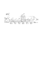
図1は、本実施の形態のシステム構成の一例を示す。無線通信システムの基地局装置として、送信電力が比較的大きい大型基地局(第1の基地局)1と、同電力が比較的小さい小型基地局(第2の基地局)2があり、例えば端末3−1は大型基地局1へ、端末3−2は小型基地局2へそれぞれコネクションを張り、データ通信(4−1、4−2)が実施できる状況にある。端末3−1と大型基地局1とのデータ通信4−1は、小型基地局2にとっては干渉信号5となる。なお、本実施例では、基地局装置間で送信電力差が大きいほど、本実施の形態が解決しようとする課題がより顕在化するため、大型基地局1と小型基地局2を送信電力で区別しているが、両基地局の送信電力が同一であっても良い。
大型基地局1および小型基地局2は、バックホールネットワーク6を介してゲートウェイ装置7、MME(Mobility Management Entity)装置(位置管理装置)8、OAM(Operation and Maintenance)装置(保守運用装置)9が接続されている。ゲートウェイ装置7は、各基地局装置やバックホールネットワーク6を含む無線アクセスネットワークの終端装置であり、各端末3と無線アクセスネットワーク外のノードとの間のデータ通信を制御する。
MME装置8は、端末3の位置管理機能を有し、端末3が基地局装置を跨ってハンドオーバする際、端末3の位置を更新する。端末3の位置を逐次管理することで、ゲートウェイ装置7から各基地局装置に流すデータの行き先が、端末3の位置に追従するよう制御する。OAM装置9は、各基地局装置に対して動作パラメータを設定する機能や、基地局装置および端末のスループットや受信電界強度などの測定データを各基地局装置から収集して、上記動作パラメータを更新する機能を有する。
OAM装置9は、図1ではゲートウェイ装置7の管理範囲であるバックホールネットワーク6に接続されているが、OAM装置9をゲートウェイ装置7の外側、すなわちコアネットワーク側、またはコアネットワークを介して接続される別ネットワーク上にあっても良い。本実施例では、OAM装置9が持つ機能のうち、例えば各基地局装置の近傍に位置する他の基地局装置のリスト、すなわちネイバーリストを各基地局装置に送信する機能に注目する。
FIG. 1 shows an example of the system configuration of the present embodiment. As base station apparatuses of a radio communication system, there are a large base station (first base station) 1 with relatively large transmission power and a small base station (second base station) 2 with relatively small power, for example, a terminal 3-1 is connected to the
The
The
Although the
図3の動作シーケンスを説明する前に、図2を用いて、本実施の形態が解決しようとする課題をより具体的に説明する。
横軸は端末および各基地局装置の位置を示し、左端は送信電力が小さい小型基地局2、右端は送信電力が大きい大型基地局1の位置を示す。縦軸は横軸の位置における上りまたは下り受信電力を示す。上り受信電力は、各基地局装置での受信電力を示し、下り受信電力は、端末3での受信電力を示す。
最初に、下り受信電力に注目する。大型基地局1から送信される信号の下り受信電力103は、大型基地局1付近が高く、大型基地局1から距離が離れるほど伝搬減衰により低下する。同様に、小型基地局2から送信される信号の下り受信電力104は、小型基地局2付近が高く、小型基地局2から距離が離れるほど伝搬減衰により低下する。大型基地局1と小型基地局2で、縦軸の開始点が異なるのは、送信電力の差を示す。
両基地局装置から送信される信号の受信電力が均衡する点が、いわゆるセルエッジ105と呼ばれる領域である。端末3は、いずれか一方の基地局装置と接続するため、他方の基地局装置からの送信信号が深刻な干渉源となる。よって、セルエッジ105は無線通信品質が最も悪い領域になりうる。
次に、上り受信電力に注目する。端末3はセルエッジ105に位置するものと仮定する。端末3は、接続する基地局装置が想定するターゲット受信電力106にて受信できるよう、送信電力を制御する。具体的には、端末3が接続する基地局装置から送信される参照信号の受信電力を測定し、別途通知される接続基地局装置の送信電力の情報から、伝搬ロスを推定する。上記ターゲット受信電力に、推定した伝搬ロスのバイアスを掛けることで、理想的には接続基地局装置にて端末3からの送信信号がターゲット受信電力106にて受信される。図2の例では、大型基地局1と小型基地局2のターゲット受信電力106を同一と仮定しているが異なってもよい。
まず、セルエッジ105に位置する端末3が小型基地局2に接続している場合を考える。このとき、端末3は小型基地局2にてターゲット受信電力106で受信できるよう、送信電力を制御する(108)。すると、小型基地局2ではターゲット受信電力106にて受信され、小型基地局2よりも端末から見て遠方に位置する大型基地局1での受信電力は、大型基地局1のターゲット受信電力106よりも大幅に低くなる。端末3からの送信信号は、大型基地局1にとっては干渉となるため、端末3からの送信信号がターゲット受信電力106を大幅に下回ることは望ましいことである。
一方、セルエッジ105に位置する端末3が大型基地局1に接続している場合を考える。このとき、端末3は大型基地局1にてターゲット受信電力106で受信できるよう、送信電力を制御する(107)。すると、大型基地局1ではターゲット受信電力106にて受信されるが、端末3から見てより近傍に位置する小型基地局2において、端末3からの送信信号がターゲット受信電力106を大幅に上回って受信される。小型基地局2にとって、大型基地局1に接続している端末3からの送信信号は干渉であり、この現象により小型基地局2にて、ターゲット受信電力106付近で受信される所望信号よりも高いレベルの干渉(109)が発生することになる。この、上り通信における干渉問題を解決することが本実施の形態の課題である。
Before describing the operation sequence of FIG. 3, the problem to be solved by the present embodiment will be described more specifically with reference to FIG.
The horizontal axis indicates the position of the terminal and each base station apparatus, the left end indicates the position of the
First, focus on downlink received power. The downlink received
The point where the received power of signals transmitted from both base station apparatuses is balanced is a so-called
Next, attention is paid to uplink received power. Assume that
First, consider a case where the
On the other hand, consider a case where the
なお、図2の例ではシャドーイングや伝搬ロスの基地局装置間の差を考慮していないが、これらの影響を考慮することで、両方の基地局装置が同一の送信電力であったとしても、同様の課題が発生する。
図3は、本実施例によるシステム全体の動作シーケンス図を示す。この例では、基地局装置としては、小型基地局2と、大型基地局2台(1−1および1−2)、端末3としては小型基地局2に接続する端末A(3−2)、および大型基地局1−1に接続する端末B(3−1)と端末C(3−3)を考慮する。大型基地局1−2には端末3が接続していないが、本実施例による小型基地局2からのマルチキャスト伝送(S207)の受信先が、大型基地局1−1以外にも存在することを示すために配置している。
端末A(3−2)は小型基地局2と接続(S201−1)が確立されており、端末B(3−1)と端末C(3−3)は、大型基地局1(1−1)と接続(S201−2、S201−3)が確立されている。この状態で、端末Aが小型基地局2から、端末Bが大型基地局1−1からそれぞれ、上りデータの送信許可である上りGrant(S202−1、S202−2)を受信する。上りGrantを受信した端末Aと端末Bは、同受信からプロトコルで約束された一定時間後に上りデータ(S203−1、S203−2)を送信する。この時、上りデータは相互に干渉するが、本実施例では端末Bから小型基地局2への干渉(S204)に注目する。
小型基地局2は、端末からの上り送信間隔(TTI;Transmission Time Interval)毎に上りの干渉電力を監視し、あらかじめ設定したしきい値以上の干渉電力検出を試みる(S205)。例えば、自基地局に接続する端末以外から受信される電力を、干渉電力とすることができる。小型基地局2は、しきい値以上の干渉電力を検出したら、これを継続監視し、どのような時間および周波数規則を以ってしきい値以上の干渉電力が発生するか(干渉発生規則)を推定する(S206)。例えば、予め定められた監視時間の間にしきい値以上の干渉電力を検出した時間情報(サブフレーム情報)及び周波数情報を記憶し、記憶したデータに基づき、干渉発生規則を推定する。小型基地局2は、S206で推定した干渉発生規則を、小型基地局2がOAM装置9から設定される近傍基地局のリスト、すなわちネイバーリストを参照して、近傍基地局、図3では大型基地局1(1−1)と大型基地局2(1−2)へマルチキャストする(S207)。
同マルチキャスト情報を受信した小型基地局2の近傍基地局、すなわち大型基地局1(1−1)と大型基地局2(1−2)は、それぞれ小型基地局2に対して大きな干渉を及ぼしている自基地局配下の端末特定(S208−1、S208−2)を試みる。端末特定に当たっては、大型基地局1(1−1)と大型基地局2(1−2)の各々がマルチキャスト情報を受けた時点から過去にさかのぼって、自身の端末への上りリソース割当て実績(履歴)とマルチキャストで受信した干渉発生規則に関する情報との照合を行う。各近傍基地局(ここでは各大型基地局)は、自基地局に接続するある端末への上りリソース割当て実績と、マルチキャストで受信した干渉発生規則が一致すれば、当該端末が小型基地局2への大きな干渉源と特定し、どの端末の上りリソース割当て実績とも同干渉発生規則が一致しなければ、該当端末はなし、と判断する。なお、完全に一致する以外にも、差が予め定められた許容範囲内にある端末でもよい。例えば、上りリソース割当て実績と干渉発生規則とに基づき予め定められた規則で求められる指標にしたがい、上記許容範囲内にあるか否かを判断してもよい。
In the example of FIG. 2, the difference between shadowing and propagation loss between base station apparatuses is not considered. However, even if both base station apparatuses have the same transmission power by considering these effects, A similar problem occurs.
FIG. 3 shows an operation sequence diagram of the entire system according to this embodiment. In this example, as a base station device, a
Terminal A (3-2) is connected to the small base station 2 (S201-1), and terminal B (3-1) and terminal C (3-3) are connected to the large base station 1 (1-1). ) And a connection (S201-2, S201-3) are established. In this state, terminal A receives uplink Grant (S202-1 and S202-2), which is transmission permission of uplink data, from
The
The base stations in the vicinity of the
与干渉端末特定(S208−1、S208−2)の後段に控えるハンドオーバ判定(S209−1、S209−2)は、本実施例によるハンドオーバ判定と、従来のハンドオーバ判定の2種類の処理を含んでいる。
本実施例によるハンドオーバ判定では、S208で特定した与干渉端末を、干渉を及ぼす先である小型基地局2へハンドオーバさせた場合に、下り通信品質の面で支障がないかどうかを判定し、支障がなければ当該端末にハンドオーバを実施するという判定を下す。本実施例は、大きな上り干渉電力の検出を以ってハンドオーバを促進する実施例であるが、干渉源端末の接続先基地局を、上り受信電力のみで判定すると、端末での下り受信電力をまったく考慮せずにハンドオーバすることとなり、結果として端末が接続基地局をスイッチしようとしても接続不可となる場合がある。この課題を回避するため、S208で上り干渉電力ベースで選択した端末に対し、下り通信品質の面でもハンドオーバさせて問題ないかどうか判定することとする。
従来のハンドオーバ判定は、端末が常時測定し、接続先基地局に対して定期的またはイベントドリブンで報告する下り受信電力を、接続先基地局が自基地局と近傍基地局について比較し、近傍基地局の下り受信電力が、接続先基地局の下り受信電力に、OAM装置9から設定される一定のバイアス値を加えたものよりも大きければ、当該端末に対してハンドオーバを実施するという判定を下す。
The handover determination (S209-1, S209-2) to be kept behind the interfering terminal identification (S208-1, S208-2) includes two types of processing: handover determination according to this embodiment and conventional handover determination. Yes.
In the handover determination according to the present embodiment, when the interfering terminal specified in S208 is handed over to the
In conventional handover determination, the terminal base station constantly measures the downlink received power that is regularly or event-drivenly reported to the connected base station, and the connected base station compares the local base station with the neighboring base station. If the downlink reception power of the station is greater than the downlink reception power of the connected base station plus a certain bias value set from the
なお、本実施例によるハンドオーバ判定は、上記マルチキャスト情報を受信した時に実施されるイベントドリブン型の処理であり、従来のハンドオーバ判定は、TTI毎に実施される定期的なものである。
ハンドオーバ判定(S209−1、S209−2)にて、ハンドオーバを実施すると判定された端末が基地局内に存在すると、端末や移動先基地局に対してハンドオーバを働きかけるフェーズに移行する。図3では、大型基地局1(1−1)に接続し、小型基地局2へ大きな干渉(S204)を及ぼしていた端末B(3−1)が、ハンドオーバ実施判定を受けた(ハンドオーバを実施すると判定された)と仮定して説明する。
ハンドオーバを実施すると判定した大型基地局1(1−1)は、ハンドオーバでの移動先であり、ハンドオーバ対象の端末が大きな干渉を及ぼしていた小型基地局2に対し、当該端末に関するハンドオーバリクエスト(S210)をユニキャスト送信する。同リクエストを受信した小型基地局2は、当該端末を受け入れるだけのリソース、具体的には無線リソースおよびハードウェア(プロセッサおよびメモリ)リソースが十分にあれば、当該端末のハンドオーバを受け入れる旨の応答を大型基地局1(1−1)宛にユニキャスト応答する(S211)。もし、受け入れ不可であればNAK(Non−Acknowledgement)を応答すれば動作に支障はないが、S210とS211での無駄な通信を防ぐために、小型基地局2が干渉規則をマルチキャスト(S207)する前に、当該端末の受け入れリソースが不足している場合はマルチキャストを実施しない、というポリシーで運用することが合理的である。なぜならば、小型基地局2は、マルチキャストを実施する段階で、無線リソースやハードウェアリソースが、新規端末を受け入れ可能かどうかを知っているためである。
小型基地局2からハンドオーバリクエスト(S210)に対するACK(Acknowledgement)(S211)を受信したら、大型基地局1−1は、ハンドオーバコマンド(S212)を端末Bに対して送信する。
端末Bは、同コマンドを受信したら、同コマンドの中で指示された基地局、すなわちここでは小型基地局2に対する接続を試みる。具体的には、小型基地局2から定期的に送信される下り同期信号(S213)を参照して下りの受信タイミング同期を図り、上り送信タイミングは下り受信タイミングと揃っていると仮定した状態で、小型基地局2に対して初期接続処理(S214)を実施する。この初期接続処理により、上り送信タイミングを小型基地局2の受信タイミングにフィットするよう補正し、小型基地局2から小型基地局2内でローカルに使用する端末のIDを付与される。以上の処理が完了すると、端末Bは小型基地局2との接続が確立し、データ通信が可能となる。
なお、S210以降の処理を含むハンドオーバシーケンスのより詳細な情報は[非特許文献1]、ハンドオーバリクエストの詳細は[非特許文献2]および[非特許文献3]、ハンドオーバコマンドの詳細は、RRCConnectionReconfigurationメッセージとして[非特許文献4]、初期接続処理に関する詳細は、Random Access Procedureとして[非特許文献5]にそれぞれ開示されている。
図4Aは、小型基地局2−1からの干渉規則情報のマルチキャスト範囲を示す図である。この図の中には、例えば大型基地局が3台(1−1、1−2、1−3)と、小型基地局が2台(2−1、2−2)あり、端末3−1は大型基地局1−1に対しデータ信号4−1を送信する。このデータ信号4−1は、小型基地局2−1にとっては深刻な干渉信号5となるが、その他の基地局に対しては、受信電力の観点で無視できる干渉信号であると仮定している。
The handover determination according to the present embodiment is an event-driven type process that is performed when the multicast information is received, and the conventional handover determination is a periodic one that is performed for each TTI.
If a terminal determined to perform handover in the handover determination (S209-1, S209-2) is present in the base station, the process proceeds to a phase in which the terminal or the destination base station is subjected to handover. In FIG. 3, the terminal B (3-1) connected to the large base station 1 (1-1) and causing a large interference (S204) to the
The large base station 1 (1-1) determined to perform the handover is the handover destination (S210) for the
When receiving the ACK (Acknowledgement) (S211) for the handover request (S210) from the
When the terminal B receives the command, the terminal B tries to connect to the base station indicated in the command, that is, the
Note that more detailed information of the handover sequence including the processing after S210 is [Non-Patent Document 1], the details of the handover request are [Non-Patent Document 2] and [Non-Patent Document 3], and the details of the handover command are the RRCConnectionReconfiguration message. [Non-Patent Document 4], details regarding the initial connection processing are disclosed in [Non-Patent Document 5] as Random Access Procedures.
FIG. 4A is a diagram illustrating a multicast range of interference rule information from the small base station 2-1. In this figure, for example, there are three large base stations (1-1, 1-2, 1-3) and two small base stations (2-1, 2-2), and the terminal 3-1 Transmits a data signal 4-1 to the large base station 1-1. The data signal 4-1 is a
図3のシーケンス図に従うと、小型基地局2−1が、大型基地局1−1に接続する端末3−1からの大きな受信電力の干渉信号5を受信したら、同干渉信号の発生規則を測定し、近傍基地局と判断する近傍基地局グループ10に対して、測定した干渉発生規則の情報を、バックホールネットワーク6を介してマルチキャスト送信する。どの基地局が近傍基地局グループ10に所属するかを示す情報、すなわち小型基地局2−1のネイバーリストは、事前にOAM装置9から小型基地局2−1に配信され、後述するネイバーリストバッファに記憶される。なお、ネイバーリストの中に大型基地局と小型基地局が混在していても、いずれか単一しか存在していなくても良い。
図4Bに、ネイバーリストの構成例を示す。この図に示すように、ネイバーリストは近傍基地局の数と、各近傍基地局を特定する情報で構成される。各近傍基地局を特定する情報として、無線通信区間で使用するセルIDや、バックホールネットワーク6で相互通信するのに必要なIPアドレス、またはIPアドレス相当の各基地局装置を一意に特定するアドレス情報を含む。
図5は、本実施例による小型基地局2のフローチャートを示す。小型基地局2は、本フローチャートと並行して通常のデータ通信も行っている。本フローチャートのSTARTは、例えば小型基地局装置2が起動した時点を示しており、TTI毎に図示するループを繰り返すことを想定している。
小型基地局2は、TTI毎に大きな受信電力の干渉が発生しているかどうかを判定する(S1001)。例えば上述のS205のように、予め設定したしきい値以上の干渉電力が発生しているか判定する。大きな干渉電力が発生していると判断したら、Monitoring Timerを起動して、同TimerがExpireするまで大きな受信電力の干渉を監視して、大きな受信電力が発生したタイミングと周波数位置をログに残す(S1002)。その発生規則を測定する。同TimerはTTI毎にカウントアップする。また、同TimerがExpireするまでのTTI数は、OAM装置9から設定されることができる。
小型基地局2は、同TimerがExpireした(S1004)後、S1003で作成した大きな干渉受信電力が発生したタイミング及び周波数位置を示すログに基づき、干渉発生規則を抽出する(S1005)。具体的には、大きな干渉受信電力が発生するTTI周期と、基準TTI(例えば10TTIをひと固まりとして、その先頭TTIを基準TTIとする。)からのTTIオフセットと、基準周波数リソースから一番最初に発生(検出)した大きな干渉受信電力の周波数リソース位置を示す周波数リソースオフセットと、大きな干渉受信電力が発生するたびに周波数リソースの位置がどの程度ずれるかを示す周波数リソースシフトとを抽出し、記憶する。
S1005が完了すると、小型基地局2はネイバーリストが示す近傍基地局に対し、S1005で推定した干渉発生規則をデータパケットとして生成したものをマルチキャストする(S1006)。
According to the sequence diagram of FIG. 3, when the small base station 2-1 receives the
FIG. 4B shows a configuration example of the neighbor list. As shown in this figure, the neighbor list is composed of the number of neighboring base stations and information identifying each neighboring base station. As information for identifying each neighboring base station, a cell ID used in the wireless communication section, an IP address necessary for mutual communication in the
FIG. 5 shows a flowchart of the
The
The
When S1005 is completed, the
また、小型基地局2がネイバーリストを有する以外にも、各基地局に対するネイバーリストを記憶する装置を備え、小型基地局2がマルチキャスト送信する干渉発生規則を含むデータパケットを該装置に送信し、該装置が小型基地局2に対応するネイバーリストに基づいて、小型基地局2の近傍基地局にデータパケットを転送するようにしてもよい。
以上の過程において、大きな干渉受信電力をもたらす端末の所属基地局が特定できれば当該所属基地局へのユニキャスト伝送でも良いが、以下に示すように困難である。
例えば、当該端末固有のスクランブルが掛かったデータ信号をブラインドデコードして、データに付加されているCRC(Cyclic Redundancy Check)ビットを用いた検査を行うアプローチが第一に考えられるが、端末ID、変調方式、符号化率、割り当て周波数リソース量と周波数位置といった上りリソース割り当て情報が不明のため、ブラインドデコードに伴うパラメータの空間が大きすぎて、端末特定は困難を極める。この問題を解決するため、大型基地局1−1から小型基地局2に対し、リアルタイムで上記割り当て情報を送ることも考えられるが、バックホールネットワーク6を介した基地局間通信の通信容量圧迫のため現実的ではない。
また、当該端末固有の参照信号を用いた端末特定方法も考えられるが、小型基地局2側で受信される参照信号は、端末が送信する元の参照信号に無線伝搬路応答が乗算された形となる。通常、参照信号は、参照信号そのものが送受信側双方で既知であることを前提とし、不定量である無線伝搬路応答を推定するために使用するが、ここで議論している用法では、参照信号そのものを推定する必要がある。無線伝搬路応答が既知であれば参照信号を推定できるが、上記の通り無線伝搬路応答は不定量のため、参照信号を用いたアプローチによる端末特定は困難である。よって、本実施例では小型基地局2で、大型基地局1−1に所属する与干渉端末の特定は困難であるとの考え方から、大きな干渉受信電力が発生した時間周波数位置のみを特定し、近傍基地局へマルチキャストするアプローチを採っている。
In addition to the
In the above process, unicast transmission to the affiliated base station may be performed as long as the affiliated base station of the terminal that causes large interference reception power can be identified, but this is difficult as described below.
For example, the first approach is to blindly decode a scrambled data signal unique to the terminal and perform a check using a CRC (Cyclic Redundancy Check) bit added to the data. Since uplink resource allocation information such as scheme, coding rate, allocated frequency resource amount and frequency position is unknown, parameter space associated with blind decoding is too large, and terminal identification is extremely difficult. In order to solve this problem, it is conceivable that the allocation information is sent in real time from the large base station 1-1 to the
A terminal identification method using a reference signal unique to the terminal is also conceivable, but the reference signal received on the
図6は、本実施例による大きな干渉電力を検出する方法を示す図である。
横軸は、小型基地局2の上り用周波数リソースの番号である。例えば、LTE(Long Term Evolution)の標準規格に従うと、各周波数リソース303−1〜6はリソースブロック(RB;Resource Block)と呼ばれ、15kHzサブキャリアを12本束ねた180kHz幅となる。縦軸は、周波数リソース毎の上り受信電力密度(303−1から301−6)である。上り受信電力の中には、小型基地局2に所属し、小型基地局2が当該周波数リソースで通信を許可した、すなわち上りGrantを発行した端末からの上り信号と、近傍基地局に所属し、当該近傍基地局から上りGrantの発行を受けた端末からの上り信号とが混在している。
近傍基地局に所属する端末からの上り信号が、当該基地局に所属する端末からの上り信号に対し無視できる受信電力であれば、当該基地局に接続する端末は、当該基地局のターゲット受信電力(301)に合わせて送信電力を制御するため、図示する通り各周波数リソースの受信電力密度(303−1から303−3および303−5、303−6)はターゲット受信電力付近に分布する。上り送信電力を決定した時点の伝搬路と、実際に当該送信電力で送信した時の伝搬路が完全一致するとは限らないため、周波数リソースによってターゲット受信電力に対し上下に分布する。
ただし、近傍基地局に所属する端末からの大きな受信電力の干渉信号が到来すると、当該端末に割り当てられた周波数リソースにおいて、ターゲット受信電力301を大幅に上回る受信電力密度が検出される。どの程度ターゲット受信電力301を上回った時に、大きな受信電力の干渉信号が発生したかどうかを判定するために、受信電力密度しきい値(302)を設ける。同しきい値を上回った受信電力密度を検出した周波数リソースにおいて、大きな受信電力の干渉信号が発生したと判断し、図5のS1003に記載している通り、干渉信号発生時間および周波数をログに残す。受信電力密度しきい値302は、例えばターゲット受信電力301に対して干渉検出のためのバイアス値(304)を上乗せした値とする。
FIG. 6 is a diagram illustrating a method for detecting large interference power according to the present embodiment.
The horizontal axis is the number of the uplink frequency resource of the
If an uplink signal from a terminal belonging to a neighboring base station is a received power that can be ignored with respect to an uplink signal from a terminal belonging to the base station, the terminal connected to the base station must receive the target received power of the base station. In order to control the transmission power in accordance with (301), the reception power density (303-1 to 303-3 and 303-5, 303-6) of each frequency resource is distributed in the vicinity of the target reception power as shown in the figure. Since the propagation path at the time of determining the uplink transmission power and the propagation path when actually transmitting with the transmission power are not necessarily completely matched, they are distributed up and down with respect to the target reception power depending on the frequency resource.
However, when an interference signal having a large received power from a terminal belonging to a neighboring base station arrives, a received power density that is significantly higher than the target received
ターゲット受信電力301および干渉検出のためのバイアス値304は、OAM装置9から小型基地局2に対して設定することができる。なお、ターゲット受信電力301に関しては、OAM装置9から設定された値を初期値として、小型基地局2で測定した周波数毎の受信電力密度を長時間平均したものを用いても良い。
なお、図6の実施例では、[特許文献1]に開示されているような自基地局と端末間で通信しない零区間の概念は採り入れていない。零区間を導入することで干渉検出精度向上が見込まれるが、小型基地局に接続する端末へ割当てる通信リソース量、ならびにスループットが減少するため、本実施例ではターゲット受信電力に対してバイアスしたしきい値に対する判定を用いている。この方法により、大きい受信電力の干渉を受信していない周波数リソースを有効に活用できる効果がある。
図7Aおよび図7Bは、図5のS1003に示す大きな干渉受信電力を検出した時間及び周波数位置をログに残す方法について説明する図である。これら2つの図は、大きな干渉受信電力の発生する規則が異なるのみで、それ以外は同一の図である。
これらの図の四角いマス目は、基地局装置が端末に対して割当てられる通信リソースの最小単位を示す。時間方向(図中横方向)はTTI単位、本図では1msのサブフレームと表記している。周波数方向(図中縦方向)は、端末に割り当てられる周波数リソースの最小単位毎にマス目を区切っている。ここでは、上記LTEのリソースブロックサイズに従い180kHzとしている。また、測定及び記録期間を本図ではサブフレーム数を12、周波数リソースの数を8としているが、この数に限定するものではない。また、一番左側のマス目を基準サブフレーム311、例えばLTEでは10サブフレームで1無線フレームが構成されているが、無線フレーム先頭のサブフレームを基準サブフレームとする。同様に、一番下側のマス目を基準周波数リソース312、例えば全周波数リソースのうち、最も低い周波数に位置するリソースブロックを基準周波数リソースとする。
白いマス目314は、大きな干渉受信電力が検出されなかったサブフレームやリソースブロックを示し、塗りつぶしたマス目313は、大きな干渉受信電力が検出されたサブフレームやリソースブロックを示す。
The target received
In addition, in the Example of FIG. 6, the concept of the zero section which is not communicating between an own base station and a terminal which is disclosed by [patent document 1] is not taken. Although the interference detection accuracy can be improved by introducing the zero interval, the amount of communication resources allocated to the terminal connected to the small base station and the throughput are reduced. Judgment on value is used. By this method, there is an effect that it is possible to effectively use frequency resources that do not receive interference of large reception power.
FIG. 7A and FIG. 7B are diagrams for explaining a method of leaving the time and frequency position at which a large interference reception power is detected in S1003 of FIG. 5 in the log. These two figures are the same except that the rules for generating large interference reception power are different.
The square boxes in these figures indicate the minimum unit of communication resources that the base station apparatus can allocate to the terminal. The time direction (horizontal direction in the figure) is expressed as a TTI unit, and in this figure, it is expressed as a 1 ms subframe. In the frequency direction (vertical direction in the figure), squares are divided for each minimum unit of frequency resources allocated to the terminal. Here, the frequency is set to 180 kHz in accordance with the LTE resource block size. In the drawing, the number of subframes is 12 and the number of frequency resources is 8 in this figure, but the measurement and recording period is not limited to this number. In addition, although one radio frame is composed of a
図7Aでは、大きな干渉受信電力が、基準サブフレームから数えて2つ目を先頭に、4サブフレームおき、周波数方向は基準周波数リソースから数えて7つ目で発生し、大きな干渉受信電力が発生する度の周波数リソースのシフトは発生していない例である。図7Bでは、大きな干渉受信電力が、基準サブフレームから数えて1つ目を先頭に、2サブフレームおき、周波数方向は基準周波数リソースから数えて5つ目で最初の干渉受信電力が発生し、大きな干渉受信電力が発生する度の周波数リソースのシフトは、上側に数えて上端で折り返すこととすると6周波数リソース分のシフトが発生している例である。このように推定した干渉発生規則をマルチキャストメッセージとして、ネイバーリストに記載されている近傍基地局へ伝送する。マルチキャストメッセージに関する実施例は図8Aおよび図8Bに記載する。
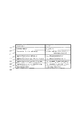
図8Aは、図7Bに示す干渉発生規則をマルチキャストメッセージとして構成した場合の実施例である。マルチキャストメッセージの構成は、送信元となる小型基地局2のセルID401、小型基地局が干渉発生規則の測定を開始したサブフレームの番号402、同じく測定を継続した期間403、大きい干渉受信電力を検出したサブフレーム周期404および基準サブフレームからのオフセット405、大きい干渉受信電力を402および403で示される測定期間の中で最初に検出したリソースブロックのインデックス(オフセット)406および大きい干渉受信電力を検出する度に発生するリソースブロックのシフト量407、及び、どの種類の物理チャネルや信号を使用して大きい干渉受信電力を検出したかを示すインジケータ408を含む。
In FIG. 7A, a large interference reception power is generated when the second interference frequency is counted from the reference subframe, and every fourth subframe, and the frequency direction is the seventh frequency counting from the reference frequency resource. This is an example in which a frequency resource shift does not occur every time. In FIG. 7B, the first interference reception power is generated when the large interference reception power is counted from the reference subframe, and every second subframe, and the frequency direction is counted from the reference frequency resource. The frequency resource shift every time a large amount of interference reception power is generated is an example in which a shift corresponding to six frequency resources occurs when counting up to the upper end and turning back at the upper end. The interference occurrence rule estimated in this way is transmitted as a multicast message to neighboring base stations described in the neighbor list. Examples for multicast messages are described in FIGS. 8A and 8B.
FIG. 8A is an example when the interference occurrence rule shown in FIG. 7B is configured as a multicast message. The structure of the multicast message consists of the
セルID401は、小型基地局2がシステムエントリーした時にOAM装置9から設定される値である。サブフレーム番号402は、小型基地局が起動してからの通し番号で、例えば32bitsの値域を持ち、32bitsの範囲を超えると0に折り返す数字である。なお、基準サブフレームは、例えばLTEでは10サブフレームで1無線フレームとなるため、サブフレーム番号を10で割った余りが0となるサブフレーム番号に相当する。干渉発生規則の測定期間403は、OAM装置9から設定される値である。404から407に示す干渉発生規則は、小型基地局2における測定値(推定値)がセットされる。Measurement Object408は、干渉発生規則に用いた物理チャネルや信号を表すインジケータであるが、これはOAM装置9から設定される。
図8Bは、図8Aをより一般化した表現である。401から408が採りうる値域を示したものであり、本マルチキャストメッセージを受信する基地局が、基地局間で約束されたプロトコルとして各フィールド長を把握しておくことで、ブラインド処理を行う必要が無いため、マルチキャスト受信処理を効率化することができる。
図9は、本実施例による大型基地局1の動作を示すフローチャートである。本フローチャートは、本実施例によるハンドオーバ判定を示す左側と、従来のハンドオーバ判定を示す右側とに大きく分かれている。図5で示した小型基地局2のフローチャートと同様、STARTは大型基地局1が起動した時点を示し、TTI毎に動作を繰り返すことを想定している。
ステップS2001では、大型基地局1は、TTI毎に近傍基地局から、図8Aや図8Bで示す干渉発生規則情報を示すマルチキャスト情報を受信したかどうかを判定する。マルチキャスト情報を受信していない場合は、図中右側の従来のハンドオーバ判定処理を開始する。一方、マルチキャスト情報を受信した場合は、次のステップS2002へ進む。
ステップS2002では、大型基地局1は、マルチキャスト情報として受信した干渉発生規則と、マルチキャスト情報を受信した基地局自身が、所属端末に対して上り通信リソースを割り当てた記録(ログ情報)との照合を行い、マルチキャスト情報の送信元である基地局に対し、大きな干渉信号をもたらしている端末が自基地局の所属端末の中に存在するかどうかを探索する。ステップS2003で該当端末が存在するか否かにより条件分岐する。該当端末が不在であれば、図中右側の従来ハンドオーバ処理を開始し、一方、該当端末が存在すれば、ステップS2004へ進む。
The
FIG. 8B is a more generalized representation of FIG. 8A. 401 to 408 indicate the range that can be taken, and it is necessary for the base station receiving this multicast message to perform blind processing by grasping each field length as a protocol promised between the base stations. Therefore, the multicast reception process can be made more efficient.
FIG. 9 is a flowchart showing the operation of the
In step S2001, the
In step S2002, the
ステップS2004では、大型基地局1は、ステップS2002で特定された端末の、マルチキャスト情報送信元の基地局に関する下り受信電力を取得する。端末は基地局へ接続する際、所属基地局および周辺基地局に関する下り受信電力を測定し、定期的にまたは下り電力の基地局間相互関係の変化をトリガとしたイベントドリブンにより所属基地局へ報告するようコンフィグされる。ステップS2004が始まる段階で、端末から所属基地局と、マルチキャスト送信元の近傍基地局とに関して、下り受信電力が収集できていれば、既収集値を参照すれば良い。ただし、報告するための上りデータ量の節約や、下り電力測定に要する端末の消費電力低減の観点から、所属基地局に関する下り電力がしきい値を下回らない限り、周辺基地局に関する下り受信電力の測定や報告を停止する場合がある。この場合、当該端末に対し、マルチキャスト情報送信元の基地局に関する下り受信電力を測定し、報告するようコンフィグを再度行う必要がある。当該端末が測定すべきセルIDは、マルチキャスト情報に含まれている。
ステップS2005では、大型基地局1は、S2004で取得した当該端末のマルチキャスト送信元基地局に関する下り受信電力が予め定められたしきい値を超えているかどうかを判定する。しきい値は、下り通信が可能か不可能かの分かれ目を示す値で、OAM装置9から設定される。上記下り受信電力がしきい値を下回っていれば、大型基地局1は、当該端末をマルチキャスト送信元基地局に移動(ハンドオーバ)しても下り通信が不通になる可能性があると判断し、本実施例によるハンドオーバ処理は実施せず、図中右側の従来のハンドオーバ処理を開始する。上記下り受信電力がしきい値を上回っていればステップS2006へ進む。
ステップ2006では、大型基地局1からマルチキャスト送信元基地局に対し、当該端末に関するハンドオーバリクエストを発行し、マルチキャスト送信元基地局からの応答を待つ処理である。当該端末の受け入れ先となるマルチキャスト送信元基地局における無線およびハードウェアリソースが十分にあればACK、不十分であればNAKが大型基地局1へ返される。NAKの場合は、当該端末に関するハンドオーバ処理は行わず、図中右側の従来のハンドオーバ処理へ進む。ACKであれば、ステップ2007で当該端末に対してハンドオーバコマンドを発行し、実際のハンドオーバ処理を開始する。
図3の説明でも述べた通り、従来のハンドオーバ処理に関する詳細は[非特許文献1]、[非特許文献2]、[非特許文献3]、[非特許文献4]ならびに[非特許文献5]に開示されている。
In step S2004, the
In step S2005, the
In step 2006, the
As described in the description of FIG. 3, details regarding the conventional handover processing are [Non-patent document 1], [Non-patent document 2], [Non-patent document 3], [Non-patent document 4], and [Non-patent document 5]. Is disclosed.
次に、図中右側に示す従来のハンドオーバ処理を説明する。なお、以下に示す処理以外にも、適宜のハンドオーバ処理を用いてもよい。
ステップS2011では、大型基地局1は、各端末に関して所属基地局に関する下り受信電力と、近傍基地局の下り受信電力のうち最大値とを取得する。ただし、既に述べた通り、端末の動作簡略化のため、下り受信電力の基地局間相互関係により、近傍基地局の情報が入手できていない場合があるが、そのような端末はハンドオーバ候補端末から外す。
ステップS2012では、所属基地局に関する下り受信電力と、近傍基地局の下り受信電力のうち最大値が入手可能な端末を対象に、下り受信電力同士の比較を行う。原則としては、近傍基地局の下り受信電力が所属基地局のものを上回ったらハンドオーバ対象となるが、無線伝搬路変動による頻繁なハンドオーバ発生を防ぐため、通常ヒステリシスを持った制御を行う。つまり、所属基地局の下り受信電力にバイアスを掛け、バイアスを掛けた所望信号に関する下り受信電力を、近傍基地局の下り受信電力が上回った時、当該端末をハンドオーバ候補とし、当該近傍基地局を移動先の基地局とする。この処理によりハンドオーバ候補となる端末が存在すればステップS2013へ進み、存在しなければ当該TTIにおけるハンドオーバ処理は終了する。
ステップS2013とステップS2014は、ハンドオーバ対象の端末と、移動先の基地局が異なるのみで、ステップS2006およびステップS2007と同様の処理である。
図10Aと図10Bを用いて、マルチキャスト情報を受信した大型基地局1において、マルチキャスト送信元基地局に対して大きなレベルの干渉をもたらしている端末の特定処理に関する第一の例を説明する。
図10Aは、大型基地局1が受信したマルチキャスト情報の一部である。図8Aに記載されている情報の一部を再度記載したものである。
図10Bは、マルチキャスト情報を受信した大型基地局1が、マルチキャスト情報に含まれるサブフレーム番号を先頭とした端末への周波数リソース毎のデータ通信に関するリソース割り当て情報を時系列に並べたものである。基地局による端末へのデータ通信割り当ては、TTI単位で動的に割り当て端末を変更するダイナミックスケジューリングを前提とする。仮に、端末への割当TTI間隔や周波数リソースの配置規則が分かれば、図11Bで示すような、より簡易なアプローチを採ることができる。図10Bは、端末へのリソース割当てがダイナミックスケジューリングに基づくため、例えば基地局自身が図10Bに示すようなログを残しておくことで、本実施例で期待する端末特定処理を実施することができる。
図10Bは、縦方向に周波数リソースのインデックスが並び、横方向にマルチキャスト情報が指示する干渉規則測定期間の先頭から順番にTTI毎の列が形成される。各マス目に記載されている情報は、当該周波数リソースおよびTTIにおける割り当て端末(uid;user equipment identifier)を示す。この表に、図10Aに示される干渉規則が示す周波数リソースおよびTTIを灰色ハッチ509でオーバーラップさせると、マルチキャスト情報送信元の基地局へ大きな干渉を及ぼす端末を特定できる。この図の例では、uid=3の端末が該当端末として特定される。灰色ハッチの範囲に複数の端末が存在する場合、例えば端末特定ができなかったものとして処理してもよい。
Next, a conventional handover process shown on the right side in the figure will be described. In addition to the processes shown below, an appropriate handover process may be used.
In step S2011, the
In step S2012, the downlink received powers are compared with each other with respect to the terminal that can obtain the maximum value of the downlink received power related to the base station and the downlink received power of the neighboring base station. In principle, if the downlink received power of a neighboring base station exceeds that of the base station to which it belongs, it becomes a handover target. However, in order to prevent frequent handovers due to radio channel fluctuations, control with normal hysteresis is performed. That is, when the downlink received power of the base station to which the affiliated base station is biased and the downlink received power related to the biased desired signal exceeds the downlink received power of the neighboring base station, the terminal is set as a handover candidate, and the neighboring base station is The destination base station. If there is a candidate terminal for handover by this process, the process proceeds to step S2013, and if there is no terminal, the handover process in the TTI ends.
Steps S2013 and S2014 are the same as steps S2006 and S2007, except that the handover target terminal and the destination base station are different.
10A and 10B, a first example relating to a process of identifying a terminal that has caused a large level of interference with a multicast transmission source base station in the
FIG. 10A shows a part of the multicast information received by the
FIG. 10B is a diagram in which the
In FIG. 10B, frequency resource indexes are arranged in the vertical direction, and columns for each TTI are formed in order from the beginning of the interference rule measurement period indicated by the multicast information in the horizontal direction. The information described in each square indicates the frequency resource and an allocation terminal (uid; user equipment identifier) in the TTI. When the frequency resource and the TTI indicated by the interference rule shown in FIG. 10A are overlapped with the gray hatch 509 in this table, it is possible to identify a terminal that greatly interferes with the multicast information transmission source base station. In the example of this figure, the terminal with uid = 3 is specified as the corresponding terminal. When there are a plurality of terminals in the gray hatched range, for example, the terminal may not be specified.
図11Aと図11Bを用いて、マルチキャスト情報を受信した大型基地局1において、マルチキャスト送信元基地局に対して大きなレベルの干渉をもたらしている端末の特定処理に関する第二の例を説明する。
図11Aは、大型基地局1が受信したマルチキャスト情報である。図10Aとほぼ同様であるが、Measurement Object506をDataからReferenceへ変更している。DataとReferenceの違いは、基地局から端末に割り当てられる通信リソースがダイナミックスケジューリングか固定スケジューリングかの違いを意図している。このようなReferenceの代表として、LTE標準規格で規定されているSounding Reference Signal(SRS)がある。SRSは、端末毎に送信サブフレーム周期とサブフレームオフセットを基地局からコンフィグすることができる。周波数方向に関しては、全周波数リソースを使用するワイドバンド伝送か、各送信タイミングにて一部周波数リソースで送信し、送信タイミングの度に送信周波数リソースがホッピングするようコンフィグ可能である。このように、Referenceは、基地局から端末に対して送信方法が予めコンフィグされ、端末から一定の時間周波数規則を以って送信される信号を表す。
図11Bは、大型基地局1が所属端末各々に対し、どのようにReferenceの送信方法をコンフィグしたかを表す表である。このコンフィグ情報は例えばコンフィグの際など予め大型基地局1に記憶することができる。大型基地局1は、図11Aで示されるマルチキャスト情報と、図11Bのコンフィグ情報とを照合し、コンフィグ情報がマルチキャスト情報と一致する端末を探索する。
図11Aに示すマルチキャスト情報のうち、図11Bのコンフィグ情報と一致する情報項目は、502、503、504、505の4種類であり、これらはそれぞれ図11Bの511、512、513、514に対応する。この図の例では、User Equipment ID=3の端末が、図11Aに示すマルチキャスト情報とコンフィグ情報が一致するため、同ID=3の端末が、小型基地局2に対する大きな干渉受信電力をもたらすと判断される。もし、図11Bのようなマルチキャスト情報−コンフィグ情報間の完全一致が確認できない場合、マルチキャスト送信元基地局に対して大きなレベルの干渉をもたらしている端末を特定できないと判断してもよい。
図12Aおよび図12Bを用いて、図9のS2004に示す端末における下り受信電力を基地局が取得する方法を示す。図12Aは動作シーケンス、図12Bは基地局が取得した端末毎基地局毎の下り受信電力をテーブルにまとめたものである。
11A and 11B, a second example relating to a process of identifying a terminal that has caused a large level of interference with a multicast transmission source base station in the
FIG. 11A is multicast information received by the
FIG. 11B is a table showing how the
Among the multicast information shown in FIG. 11A, there are four types of
A method for the base station to acquire the downlink received power in the terminal shown in S2004 of FIG. 9 will be described using FIG. 12A and FIG. 12B. FIG. 12A is an operation sequence, and FIG. 12B is a table summarizing downlink received power for each base station acquired by the base station in a table.
まず、図12Aに従って、端末が下り受信電力を測定してから基地局へ報告するまでの手順を説明する。まず、端末3に対し、当該端末が接続する基地局1からMeasurement Configuration(S601)を実施する。このコンフィグレーションには、例えば、測定対象となる基地局(当該端末の接続基地局およびその近傍基地局)のセルID、測定する周波数バンド、端末が測定に専念するための、データ通信用通信リソースが割り当てられない時間期間(LTE標準規格ではMeasurement Gapと呼ばれる)、ならびに、基地局へ下り受信電力測定結果を報告する時間周期または基地局へ同測定結果を報告するためのトリガ条件(例えば、接続基地局と近傍基地局との間の下り受信電力差の条件など)が含まれる。なお、測定対象となる基地局のセルIDは、同コンフィグレーションを送信する基地局が保持するネイバーリストに基づく。
端末3は、S601にて受信したコンフィグレーションに従い、接続基地局1および近傍基地局2から送信される下り参照信号(S602−1、S602−2)を用いて、各基地局に関する下り受信電力を測定する(S603)。測定後、端末3はS601でコンフィグされた時間周期またはトリガ条件を満たした時点で、接続基地局1に対し測定結果を報告する(S604)。
図12Bは、接続基地局1に接続する各端末3から接続基地局1へ報告されるMeasurement Report(S604)に基づき作成される、端末毎かつ基地局毎の下り受信電力のテーブルである。基地局名は、図4Bに示したネイバーリストに基づいている。横方向に端末が並んでいる。原則として、端末は接続基地局からコンフィグされた全ての基地局に関する下り受信電力を測定するべきだが、端末のバッテリーライフや上り通信帯域節約の観点から、端末による測定動作やレポート動作が一部省略される場合がある。このような動作は、基地局から端末に対して、定期的なレポートではなく、イベントドリブン型のレポートコンフィグを行うことで実施される。
このとき、図12Bに示す表の一部が埋まらないこともある。ただし、図9のS2003にてある近傍基地局への大きな上り干渉を及ぼしていると特定された端末に関して、当該近傍基地局に関して当該端末から下り受信電力が報告されていない場合は、図12Aに示す動作シーケンスに従い、当該端末に対して当該近傍基地局に関する下り受信電力を報告するようS601のMeasurement Configuration以降の処理を実施することで、当該下り受信電力をS2004で取得することができる。
図13は、図12Bに示す端末毎基地局毎の下り受信電力が図12Aの動作シーケンスで収集できていることを前提として、本実施例によるハンドオーバ判定、および従来のハンドオーバ判定の違いを説明する。
図13は、横方向に基地局、縦方向に各基地局に関する下り受信電力が示された棒グラフである。このグラフは、大型基地局1−1に接続するある端末から報告された下り受信電力である。接続基地局である大型基地局1−1の他、近傍基地局である大型基地局1−2および小型基地局2−2に関する下り受信電力が、それぞれ−90[dBm]、−140[dBm]、−95[dBm]と報告されている状態である。
通常のハンドオーバ処理は、接続基地局である大型基地局1−1の下り受信電力に対し、Pb[dB]バイアスしたしきい値(621)を、近傍基地局の下り受信電力が上回ると、下り受信電力が同しきい値621を超えた近傍基地局を移動先とするハンドオーバ処理、例えば図3に示すS210以降に相当する処理が始まる。なお、バイアス値PbはOAM装置9から設定される。
First, according to FIG. 12A, a procedure from when the terminal measures downlink received power until it reports to the base station will be described. First, the measurement configuration (S601) is performed on the terminal 3 from the
In accordance with the configuration received in S601, the
FIG. 12B is a table of downlink received power for each terminal and for each base station created based on the Measurement Report (S604) reported from each terminal 3 connected to the connected
At this time, a part of the table shown in FIG. 12B may not be filled. However, for a terminal identified as causing a large uplink interference to a neighboring base station in S2003 of FIG. 9, if no downlink received power is reported from the terminal for the neighboring base station, FIG. According to the operation sequence shown, the downlink reception power can be acquired in S2004 by performing the processing after Measurement Configuration in S601 so as to report the downlink reception power related to the neighboring base station to the terminal.
13 explains the difference between the handover determination according to the present embodiment and the conventional handover determination on the assumption that the downlink received power for each base station for each terminal shown in FIG. 12B can be collected in the operation sequence of FIG. 12A. .
FIG. 13 is a bar graph showing the downlink received power for the base station in the horizontal direction and for each base station in the vertical direction. This graph is the downlink received power reported from a certain terminal connected to the large base station 1-1. In addition to the large base station 1-1 that is the connected base station, the downlink received power for the large base station 1-2 and the small base station 2-2 that are neighboring base stations is −90 [dBm] and −140 [dBm], respectively. , −95 [dBm].
In the normal handover process, when the downlink reception power of the neighboring base station exceeds the threshold (621) biased by Pb [dB] with respect to the downlink reception power of the large base station 1-1 that is the connected base station, A handover process using a neighboring base station whose received power exceeds the threshold value 621 as a movement destination, for example, a process corresponding to S210 and after shown in FIG. The bias value Pb is set from the
一方、本実施例によるハンドオーバ処理は、近傍基地局から干渉規則情報がマルチキャストされることで始まる。マルチキャスト情報発信元の基地局のセルIDは、同マルチキャスト情報内に格納されている。本実施例によるハンドオーバの実施判定は、従来と異なり、下り通信品質が良い基地局からあえて悪い基地局へ移動してでも、深刻な上り干渉を回避することが目的のため、下り通信品質は最低限下りデータ通信が成立する程度の下り受信電力が確保できていればよい。例えば下り通信が成立しかつできるだけ低い下り受信電力に設定できる。例えば、しきい値Pthrが大型基地局1−1の下り受信電力よりも小さい値に設定されることもできる。図13では−100dBmにそのしきい値Pthrを設けている。しきい値PthrはOAM装置9から設定される。
仮に、マルチキャスト情報の送信元基地局が大型基地局1−2の場合、下り受信電力が−140[dBm]であり、しきい値Pthr=−100dBmを下回っているため、近傍基地局である大型基地局1−2での上り干渉受信電力が大きいものの、当該端末を大型基地局1−2へハンドオーバさせた時に下り通信が成立しなくなると懸念されるため、ハンドオーバ処理は実施されない。
一方、マルチキャスト情報の送信元基地局が小型基地局2−2の場合、下り受信電力が−95[dBm]であり、しきい値Pthr=−100dBmを上回っているため、下り受信電力は、現在の接続基地局、すなわち大型基地局1−1には及ばないものの、近傍基地局、すなわち小型基地局2−2への深刻な上り干渉を抑えることはできるため、当該端末に対するハンドオーバ処理を開始する。
On the other hand, the handover process according to the present embodiment starts when the interference rule information is multicast from the neighboring base station. The cell ID of the base station from which the multicast information is transmitted is stored in the multicast information. Unlike the conventional case, the handover execution determination according to the present embodiment is intended to avoid serious uplink interference even when moving from a base station with good downlink communication quality to a bad base station. It suffices if the downlink received power can be secured to the extent that limited downlink data communication is established. For example, downlink communication can be established and the downlink reception power can be set as low as possible. For example, the threshold value Pthr can be set to a value smaller than the downlink received power of the large base station 1-1. In FIG. 13, the threshold value Pthr is set to −100 dBm. The threshold value Pthr is set from the
If the multicast information transmission source base station is the large base station 1-2, the downlink reception power is −140 [dBm] and is lower than the threshold value Pthr = −100 dBm. Although the uplink interference reception power at the base station 1-2 is large, there is a concern that downlink communication will not be established when the terminal is handed over to the large base station 1-2, so the handover process is not performed.
On the other hand, when the transmission source base station of the multicast information is the small base station 2-2, the downlink reception power is −95 [dBm] and exceeds the threshold value Pthr = −100 dBm. Although it does not reach the connected base station, that is, the large base station 1-1, since serious uplink interference to the neighboring base station, that is, the small base station 2-2 can be suppressed, the handover process for the terminal is started. .
なお、この条件でハンドオーバすると、ハンドオーバ後の当該端末の下り受信電力は、新たな接続基地局である小型基地局2―2が−95dBm、近傍基地局となる大型基地局1−1が−90dBmと、近傍基地局の方が下り受信電力が大きくなる。この時に発生しうる課題は2つある。1つ目は下り通信品質が低下すること、2つ目はすぐに元の大型基地局1−1に対してハンドオーバで戻ってしまう点である。
第一の課題は、各々の基地局の無線リソース使用率が低ければ、実用上あまり問題とならない。無線リソース使用率が低いと言うことは、所望信号が伝送されている無線リソースと同一無線リソースを用いた干渉信号が、確率的に発生しにくくなることを意味する。逆に言うと、確率的に下り通信品質が干渉信号により大幅に低下するが、長期的に平均化すれば、下り通信品質を改善する余地がある。ただし、この改善は無線リソース使用率に依存するため、無線リソース使用率が高く、干渉信号が発生する確率が高い場合は、LTE−Advanced標準化で規格化が検討されているeICIC(enhanced Inter Cell Interference Control)およびCoMP(Coordinated Multi−Point Transmission/Reception)の技術を活用することで、この第一の課題を回避することができる。なお、eICICに関しては[非特許文献6]、CoMPに関しては[非特許文献7]に開示されている。
When handover is performed under this condition, the downlink received power of the terminal after handover is -95 dBm for the small base station 2-2 as a new connection base station, and -90 dBm for the large base station 1-1 as a nearby base station. Then, the downlink received power is larger in the neighboring base station. There are two problems that can occur at this time. The first is that the downlink communication quality is degraded, and the second is that the original large base station 1-1 is immediately returned to the handover.
The first problem is not a practical problem if the radio resource usage rate of each base station is low. A low radio resource usage rate means that an interference signal using the same radio resource as the radio resource transmitting the desired signal is less likely to occur. In other words, the downlink communication quality is stochastically degraded due to the interference signal, but there is room for improving the downlink communication quality if averaged over the long term. However, since this improvement depends on the radio resource usage rate, if the radio resource usage rate is high and the probability of occurrence of an interference signal is high, eICIC (enhanced Inter Cell Interference) being studied for standardization by LTE-Advanced standardization This first problem can be avoided by utilizing the technology of Control) and CoMP (Coordinated Multi-Point Transmission / Reception). Note that eICIC is disclosed in [Non-Patent Document 6] and CoMP is disclosed in [Non-Patent Document 7].
第二の課題は、当該端末が小型基地局2−2側へハンドオーバしたとしても、小型基地局で実施される従来ハンドオーバ処理により、元の大型基地局1−1へ再度ハンドオーバすることとなる。この課題を回避するためには、小型基地局2−2に対し、図13で示したバイアス値Pbを比較的大きく設定することで回避できる。例えば、図13の例で小型基地局2−2のPb=6dBと設定すれば、近傍基地局に関する下り受信電力が、−95[dBm]+6[dB]=−89[dBm]を超えない限り、再度ハンドオーバが発生することはない。これを、Pb=4dBと設定すると、−95[dBm]+4[dB]=−91[dBm]となり、近傍基地局である大型基地局1−1に関する下り受信電力が−90[dBm]としきい値を上回ることになるため、ハンドオーバ後すぐに大型基地局1−1を移動先とするハンドオーバが再度発生する。バイアス値Pbは例えばハンドオーバ元の大型基地局1−1が自基地局に関する下り受信電力(例えば−90dBm)に基づき決定し、ハンドオーバ先の小型基地局2−2に通知してもよい。小型基地局2−2はこの通知に従い、バイアス値Pbを再設定してもよい。
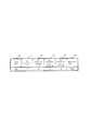
図14は、本実施の形態による小型基地局2の構成を示すブロック図である。
小型基地局2は、例えば、ネットワークインターフェース部701と、データバッファ702と、ネイバーリストバッファ703と、干渉パラメータ推定処理部(干渉規則推定部)704と、下りデータ信号処理部705と、上りデータ信号処理部706と、干渉電力測定処理部707と、リソース割当て処理部708と、無線インターフェース部709と、基地局アンテナ710とを有する。ネットワークインターフェース部701は、マルチキャスト送信部711を有する。
端末3は、アンテナ710を介して小型基地局2と無線通信を行う。無線インターフェース部709は、例えば、上りと下りで異なる無線周波数を弁別するデュプレクサ、下り無線周波数信号を増幅するパワーアンプ、上り無線周波数信号を増幅する低ノイズアンプ、下りベースバンド信号を下り無線周波数信号へ変換するアップコンバータ、上り無線周波数信号を上りベースバンド信号へ変換するダウンコンバータ、下りベースバンドデジタル信号を下りベースバンドアナログ信号へ変換するデジタルアナログ変換器、及び、上りベースバンドアナログ信号を上りベースバンドデジタル信号へ変換するアナログデジタル変換器といったアナログコンポーネントで構成される。上記低ノイズアンプは、平均受信電力に相当する出力電圧が一定となるよう、強い受信電力を弱めたり、弱い受信電力を強めたりと、入力に対するゲイン制御を適応的に行うAGC(Automatic Gain Control)の機能を具備している。
The second problem is that even if the terminal is handed over to the small base station 2-2, it is handed over again to the original large base station 1-1 by the conventional handover process performed in the small base station. In order to avoid this problem, the bias value Pb shown in FIG. 13 can be set relatively large for the small base station 2-2. For example, if Pb = 6 dB of the small base station 2-2 is set in the example of FIG. 13, the downlink received power related to the neighboring base station does not exceed −95 [dBm] +6 [dB] = − 89 [dBm]. The handover will not occur again. If this is set to Pb = 4 dB, −95 [dBm] +4 [dB] = − 91 [dBm], and the downlink received power related to the large base station 1-1 which is a neighboring base station is set to −90 [dBm]. Since the value exceeds the value, the handover with the large base station 1-1 as the movement destination occurs again immediately after the handover. For example, the large base station 1-1 that is the handover source may determine the bias value Pb based on the downlink received power (for example, −90 dBm) related to the own base station, and may notify the small base station 2-2 that is the handover destination. The small base station 2-2 may reset the bias value Pb in accordance with this notification.
FIG. 14 is a block diagram showing a configuration of the
The
The
下りデータ信号処理部705は、ユーザデータや制御情報のビット系列をデータバッファ702から読出し、LTE等の標準プロトコルに従い符号化、変調、無線リソースへのユーザデータマッピング、逆フーリエ変換などを行い、ベースバンドデジタルIQサンプリング信号を、無線インターフェース部709へ出力する。上記ユーザデータマッピングは、リソース割当て処理部708からの指示に従って制御する。
上りデータ信号処理部706は、無線インターフェース部709から入力されるベースバンドデジタルIQサンプリング信号に対し、フーリエ変換、検波、ユーザデータデマッピング、復調、復号を行い、ユーザデータや制御情報のビット系列をデータバッファ702へ書き出す。
干渉電力測定処理部707は、無線インターフェース部709から入力されるベースバンドデジタルIQサンプリング信号に対し、フーリエ変換を実施し、周波数領域となった信号に対して、TTIの時間にわたって、周波数リソース単位の受信電力を測定する。LTE標準規格の受信信号に対しては、周波数方向12サブキャリア、時間方向1サブフレームを一単位として、同範囲内のIQ受信シンボルのI成分とQ成分の2乗和を累算することで受信電力を測定する。ただし、この時点では無線インターフェース部709でAGC処理が施されているため、AGCでどの程度のゲインを掛けたかを、干渉電力測定処理部707へ入力し、上記2乗和の値を補正する必要がある。干渉電力測定結果は、後段の干渉パラメータ推定処理部704へ出力する。なお、上りデータ信号処理部706と、干渉電力測定処理部707は、入力信号をフーリエ変換する所までは共通のため、フーリエ変換処理後の出力を上りデータ信号処理部706と干渉電力測定処理部707との間でシェアしても良い。
リソース割当て処理部708は、上りおよび下り通信における無線リソース割当てを行う。本実施の形態では、図10Bや図11Bに示すような割当て結果のログを残しておくことが重要であり、割り当てアルゴリズム自体は何でも良い。各端末の通信品質に応じたリソース割り当てアルゴリズムを適用する場合、下り通信に関しては端末が測定した下り通信品質、例えばLTE標準規格ではCQI(Channel Quality Indicator)などに相当する下り通信品質情報、を端末が測定し、基地局装置へフィードバックする。つまり、CQI等の情報は上りデータ信号処理部708で処理され、出力されたビット系列、すなわちCQI等の下り通信品質情報をデータバッファ702へ格納する。リソース割当て処理部708は、この格納結果を参照し、各端末に下りリソース割り当てを実施する。
The downlink data
The uplink data
The interference power
The resource
同様に上り通信に関しては、端末が送信する参照信号、例えばSRSを使用して基地局装置が上りデータ信号処理部706でCQI等の推定を行い、推定結果をデータバッファ702へ格納する。なお、上り無線リソース割当て結果は、下りデータ信号処理部705および上りデータ信号処理部706へ通知され、下り無線リソース割当て結果は、下りデータ信号処理部705へのみ通知される。上り無線リソース割当て結果を下りデータ信号処理部705へ通知する意味は、上り割り当て情報を端末に対し上りGrantとして送信することを意図したものである。同様に、上り無線リソース割当て結果を上りデータ信号処理部706へ通知する意味は、各周波数リソースでどの端末からの信号が、どのような変調方式や符号化率等を適用しているかを入力しておくことで、ブラインドデコードに頼らず復調復号との処理を実施することを意図している。下り無線リソース割当て結果を下りデータ信号処理部705へ通知する意図は、各周波数リソースでどの端末宛のデータを、どのような変調方式や符号化率等で送信するかを指示する意図と、割当情報そのものを制御情報として、固定変調方式および固定符号化率で生成する意図を含んでいる。
干渉パラメータ推定処理部704は、干渉電力測定処理707が出力する干渉電力測定結果に対し、周波数リソース毎にしきい値判定を行い、図7Aや図7Bに示すような大きな干渉受信電力を検出した時間周波数位置をTTI毎に記録し、図5に示すフローチャートに従い、S1001からS1005の干渉発生規則抽出までを行う。
ネイバーリストバッファ703は、OAM装置9から通知される当該小型基地局2のネイバーリストを格納しておくバッファである。このネイバーリストは、マルチキャスト送信部711と、端末へのMeasurement Configurationのコンテンツとして下りデータ信号処理部705とにより参照される。
データバッファ702は、各端末に関するユーザデータおよび制御情報を一時格納するバッファである。下り方向は、ゲートウェイ7から入力されるユーザデータを一時格納し、リソース割当て処理部208の指示を受けた下りデータ信号処理部205から読みだされる。上り方向は、上りデータ信号処理部206から出力されたユーザデータおよび制御情報を一時格納し、リソース割当て処理部208が参照したり、ゲートウェイ7へ出力したりする。
Similarly, for uplink communication, the base station apparatus estimates a CQI or the like in the uplink data
The interference parameter
The
The
ネットワークインターフェース部701は、データバッファ702およびネイバーリストバッファ703と、バックホールネットワーク6との間に位置し、バックホールネットワーク6で伝送するパケットと、小型基地局側2で使用する同パケット内のペイロードとの変換を行う。パケットからペイロードを除いた部分は、ヘッダなどのバックホールネットワーク6での伝送制御(宛先アドレスなど)を行うための領域である。
マルチキャスト送信部711は、干渉パラメータ推定処理部704が出力した干渉発生規則の情報、具体的には図8Aに示すような情報を、ネイバーリストバッファ703の内容を参照して、ネイバーリストに記載されている近傍基地局グループへマルチキャスト送信する。ここで言うマルチキャストとは、機能としてマルチキャストが達成できていれば良く、例えば近傍基地局各々に対し、同一のペイロードをユニキャストしても良い。マルチキャスト送信部711は、図5に示すS1006を行う。
The
The
図15は、本実施の形態による小型基地局のデバイス構成を示す。
図14に示す各ブロックは、例えば図15に示す各デバイスで実施されることができる。
ネットワークインターフェースデバイス801は、バックホールネットワーク6に対してインターフェース機能を有するデバイスであり、バックホールネットワーク6側のケーブルを接続するソケットを具備する。様々なネットワークインターフェースカードが市販されている。
802から805は、各機能を有するプロセッサであり、各プロセッサを別々に具備しているのは、マルチプロセス処理およびプロセス間通信を想定したものである。マルチスレッドまたはマルチプロセス処理に対応したプロセッサであれば、これらの機能は1つの又は適宜の複数のプロセッサにまとめても良い。また、これらのプロセッサのプログラムは、プログラムメモリ807に格納されており、小型基地局2が起動または再起動したときに、プログラムメモリ807から各プロセッサ802から805へ読みだされる。
ネットワーク通信処理プロセッサ802は、ゲートウェイ装置7、MME装置8、OAM装置9、および他の基地局との通信処理機能を有し、受信データをメインメモリ806に書き込む機能、および送信データをメインメモリ806から読み出す機能も有する。また、干渉規則推定処理プロセッサ805がメインメモリ806にメモリバス808経由で書き込んだ干渉規則情報を、メインメモリ806に格納されているネイバーリストに従い、近傍基地局へマルチキャスト送信する機能と、OAM装置9から各プロセッサのアップデートプログラムを受信し、プログラムメモリ807に書き込む機能も有する。
リソース割当て処理プロセッサ803は、図14のリソース割当て処理部708の機能を司るプロセッサで、各端末から報告される下り通信品質、基地局自身で推定する端末毎の上り通信品質、ならびに各端末宛データの残量をメインメモリ806から取得し、いわゆるパケットスケジューリングを実施し、各無線通信リソースで通信する端末の選択と、各無線通信リソースで適用する変調方式や符号化方式を無線信号処理プロセッサ804へ通知する機能を有する。
FIG. 15 shows a device configuration of a small base station according to the present embodiment.
Each block shown in FIG. 14 can be implemented by each device shown in FIG. 15, for example.
The
The network
The resource
無線信号処理プロセッサ804は、図14の下りデータ信号処理部705および上りデータ信号処理部706の機能を司るプロセッサである。リソース割当て処理プロセッサ803から指示されたリソース割当て結果や符号化・変調方式に従い、下り通信であればリソースが割り当てられた端末のデータをメインメモリ806から読出し、上り通信であれば復調・復号結果をメインメモリ806へ書き出す処理を行う。また、上り信号に含まれる各端末の下り通信品質情報、および上り参照信号から推定する上り通信品質をメインメモリ806へ書き出す機能も有する。
干渉規則推定処理プロセッサ805は、図14の干渉電力測定処理部707および干渉パラメータ推定処理部704の機能を司る。無線信号処理プロセッサ804から周波数領域のベースバンドデジタルIQ信号を分岐出力したものを入力し、しきい値を超える干渉電力を検出する時間および周波数の規則を導出し、導出された干渉発生規則の情報をメインメモリ806へ書き出す。
The
The interference rule
RFコンポーネント809は、ベースバンドデジタルIQ下り信号を無線周波数アナログIQ下り信号へ変換する機能と、無線周波数アナログIQ上り信号をベースバンドデジタルIQ上り信号へ変換する機能とを有する。RFコンポーネント809を構成する部品は、図14の無線インターフェース部709と同様、上りと下りで異なる無線周波数を弁別するデュプレクサ、下り無線周波数信号を増幅するパワーアンプ、上り無線周波数信号を増幅する低ノイズアンプ、下りベースバンド信号を下り無線周波数信号へ変換するアップコンバータ、上り無線周波数信号を上りベースバンド信号へ変換するダウンコンバータ、下りベースバンドデジタル信号を下りベースバンドアナログ信号へ変換するデジタルアナログ変換器、及び、上りベースバンドアナログ信号を上りベースバンドデジタル信号へ変換するアナログデジタル変換器といったアナログコンポーネントで構成される。上記低ノイズアンプは、平均受信電力に相当する出力電圧が一定となるよう、強い受信電力を弱めたり、弱い受信電力を強めたりと、入力に対するゲイン制御を適応的に行うAGC(Automatic Gain Control)の機能を具備している。また、デュプレクサの無線側には、アンテナを接続するためのアンテナケーブルソケットを有する。
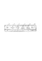
図16は、本実施の形態による大型基地局1の構成を示すブロック図である。
大型基地局1は、図14と比較して、無線インターフェース部709より無線側、およびネットワークインターフェース部701よりバックホール側は、マルチキャスト送信部711が無いことを除き、同一の構成のため、説明を省略する。また、下りデータ信号処理部705と上りデータ信号処理部706の機能、およびこれらのリソース割当て処理部208との関係は、図14のものと同一のため説明を省略する。以下、図14との差分を中心に説明する。
The
FIG. 16 is a block diagram showing a configuration of
Compared with FIG. 14, the
大型基地局1は、例えば、ネットワークインターフェース部701と、データバッファ702と、ネイバーリストバッファ703と、下りデータ信号処理部705と、上りデータ信号処理部706と、リソース割当て処理部708と、無線インターフェース部709と、基地局アンテナ710とを有し、さらに、与干渉端末特定処理部721と、下り受信電力取得処理部722と、ハンドオーバ制御処理部723と、端末コンフィグバッファ724と、リソース割当てログバッファ725を有する。
データバッファ702は、図14に記載の機能の他、下り受信電力取得処理部722が生成する図12AのMeasurement Configuration、および端末が生成したMeasurement Reportを格納する機能と、ハンドオーバ制御処理部723が、図9に示すS2006、S2007、S2013、S2014に関連するHandover Requestを発行しおよび同Requestに対するACK/NAK受信処理を行い、ならびに端末に対するハンドオーバコマンドを発行するための一時バッファとしての機能と、与干渉端末特定処理部721に対して受信したマルチキャスト情報を出力するために受信マルチキャスト情報を一時格納する機能とが追加される。
与干渉端末特定処理部721は、Measurement Objectがダイナミックスケジューリングを前提とするデータ信号の場合は、データバッファ702に一時格納されるマルチキャスト情報、具体的には図10Aや図11Aに示す形式で格納された情報と、リソース割当て処理部208がリソース割当てログバッファ725に図10Bに示す形式で格納する上りリソース割り当て情報とを照合する。また、与干渉特定処理部721は、Measurement Objectが固定スケジューリングを前提とするSRS等の参照信号の場合は、マルチキャスト情報と参照信号の送信方法の端末毎のコンフィグレーションが図11Bに示す形式で格納されている端末コンフィグバッファ724のコンフィグレーション情報を照合する処理を実施する。与干渉端末特定処理部721は、図9に示すフローチャートのうち、S2001からS2003を実行する。また、与干渉端末特定処理部は、後段の下り受信電力取得処理部722に対して、マルチキャスト情報の送信元基地局に対して大きな上り干渉を及ぼすと特定された端末のID(uid)を通知する。
The
In addition to the functions described in FIG. 14, the data buffer 702 stores the Measurement Configuration in FIG. 12A generated by the downlink received power
The interfering terminal
下り受信電力取得処理部722は、図12Aに示すシーケンスに従って収拾される各端末での下り受信電力を、図12Bの形式で保持している。端末に対して送信するMeasurement Configurationおよび端末から送信されるMeasurement Reportの情報は、データバッファ702を介して下り受信電力取得処理部722と下りデータ信号処理部705ならびに上りデータ信号処理部706との間で伝達される。与干渉端末特定処理部721が出力する端末のIDに関して、マルチキャスト情報の送信元基地局の下り受信電力を、図12Bのテーブルから、または、図12Aのシーケンスに従って取得する。下り受信電力取得処理部722は、図9のうちS2004を実施する。ここで取得した下り受信電力は、ハンドオーバ制御処理部723へ出力される。
ハンドオーバ制御処理部723は、図9のS2005、S2006、S2007、S2011、S2012、S2013及びS2014の処理を行い、制御結果に応じて近傍基地局へのハンドオーバリクエストと、移動対象端末に対するハンドオーバコマンドを、データバッファ702を介してネットワークインターフェース部701および下りデータ信号処理部705へ伝送する。
端末コンフィグバッファ724は、例えば図11Bに示すような形式で、各端末に対してコンフィグしたSRS等参照信号の送信周期などのコンフィグレーション情報を格納しておくバッファで、与干渉端末特定処理部721から参照される。
リソース割当てログバッファ725は、例えば図10Bに示すような形式で、リソース割当て処理部208が端末に対して割り当てた上り周波数リソースをログとして一時記録するバッファで、与干渉端末特定処理部721から参照される。
The downlink received power
The handover
The
The resource
図17は、本実施の形態による大型基地局のデバイス構成を示す。
図16に示す各ブロックは、例えば図17に示す各デバイスで実施されることができる。大型基地局は、図15に示す干渉規則推定処理プロセッサ805に代わり、与干渉端末ハンドオーバ処理プロセッサ811を有する。与干渉端末ハンドオーバ処理プロセッサ811は、例えば、図16に示す与干渉端末特定処理部721、下り受信電力取得処理部722、ハンドオーバ制御処理部723等の処理を行うデバイスである。他の構成について、図17の各デバイスと図16の各ブロックとの対応は、図15及び図14に示す小型基地局と同様である。
本実施の形態によると、被干渉基地局における干渉発生規則とその近傍基地局における端末へのリソース割当ログに基づき、与干渉端末を特定することができ、基地局間の通信を抑えつつ、ある基地局に対する上り干渉を低減し、同基地局に接続する端末の無線通信を安定化させることができる。
FIG. 17 shows a device configuration of a large base station according to the present embodiment.
Each block shown in FIG. 16 can be implemented by each device shown in FIG. 17, for example. The large base station has an interfering
According to the present embodiment, it is possible to identify the interfering terminal based on the interference occurrence rule in the interfered base station and the resource allocation log to the terminal in the neighboring base station, while suppressing communication between the base stations. Uplink interference with a base station can be reduced, and wireless communication of a terminal connected to the base station can be stabilized.
上述の第一の実施例では、小型基地局から干渉規則情報を近傍基地局へマルチキャスト送信する方法について説明したが、本実施例では、大きな干渉が発生したことのみを近傍基地局へマルチキャスト送信する方法を説明する。
図5に示す小型基地局のフローチャートの中で、S1005で実施している干渉規則抽出処理は、図8Aや図8Bの404から407に示すパラメータを推定するのではなく、干渉測定期間内に大きな受信電力の干渉を検出したかどうかのみを判定し、干渉が検出されたら、近傍基地局に対してマルチキャストメッセージを送信する。なお、干渉測定時間内に大きな受信電力の干渉を予め定められた回数検出した場合に、マルチキャストメッセージを通信するようにしてもよい。近傍基地局は、本マルチキャストメッセージが届いた時点で、マルチキャスト情報送信元基地局が大きな受信電力の干渉を受信していることが分かるため、干渉を検出したことを示すフィールドは、図8Aや図8Bには追加しなくてもよい。また、干渉発生規則を通知する必要がないため、図8Aや図8Bのうち、403から408のフィールドに関しては送信する必要が無い。このように、第二の実施例では、マルチキャスト情報を伝送するための通信量を削減することができる。
第二の実施例によるマルチキャスト情報を受信した大型基地局は、どの端末をマルチキャスト情報送信元基地局へハンドオーバさせるかを判定する必要がある。この判定は、図9のS2002にて実施する。具体的には、マルチキャスト情報送信元基地局に最も近いと推定される端末を、図12Bに示す下り受信電力テーブルを参照して判断する。図12Bにて、マルチキャスト情報送信元基地局を縦方向から探し、該当基地局に関して横方向、すなわち端末方向に、最も下り受信電力が大きい端末をサーチし、当該端末を与干渉端末と推定する。以降の処理は第一の実施例と同じであり、仮にS2004で当該端末の下り通信品質が十分でないと判断されれば、当該端末のハンドオーバは実施されない。
なお、干渉を検出した小型基地局からマルチキャスト情報を受信した各基地局(該小型基地局の近傍基地局)が、上述のように各基地局の下り受信電力テーブルを参照して端末を特定する。これら各端末についてハンドオーバの対象としてもよいし、各端末のうちのいずれかをハンドオーバの対象としてもよい。例えば上述のように特定された端末の下り受信電力に基づき、ハンドオーバの対象を選択してもよい。例えば上記近傍基地局間で調整してもよいし、上述のように特定された端末の下り受信電力を小型基地局に送信して小型基地局がハンドオーバの対象を選択してもよいし、上述のように特定された端末の下り受信電力が予め定められた閾値以下であればハンドオーバの対象から除外するようにしてもよい。
本実施例は、小型基地局で発生する上り干渉の発生規則に注目しないため、小型基地局に対して干渉を及ぼしている近傍基地局所属の端末を特定する精度は劣化しうるが、マルチキャスト情報の量を低減する効果が得られる。
In the first embodiment described above, the method of multicast transmission of interference rule information from a small base station to a neighboring base station has been described. However, in this embodiment, only the occurrence of large interference is multicast sent to a neighboring base station. A method will be described.
In the flowchart of the small base station shown in FIG. 5, the interference rule extraction process performed in S1005 does not estimate the parameters shown in 404 to 407 in FIG. 8A and FIG. 8B, but is large within the interference measurement period. It is determined only whether the interference of the received power is detected, and when the interference is detected, a multicast message is transmitted to the neighboring base station. Note that a multicast message may be communicated when large received power interference is detected within a predetermined number of times within the interference measurement time. Since the neighboring base station knows that the multicast information transmission source base station has received interference with a large reception power when this multicast message arrives, the field indicating that the interference has been detected is shown in FIG. 8A and FIG. It is not necessary to add to 8B. Further, since it is not necessary to notify the interference occurrence rule, it is not necessary to transmit the
The large base station that has received the multicast information according to the second embodiment needs to determine which terminal is to be handed over to the multicast information transmission source base station. This determination is performed in S2002 of FIG. Specifically, the terminal estimated to be closest to the multicast information transmission source base station is determined with reference to the downlink reception power table shown in FIG. 12B. In FIG. 12B, a multicast information transmission source base station is searched from the vertical direction, a terminal having the largest downlink reception power is searched in the horizontal direction, that is, the terminal direction with respect to the corresponding base station, and the terminal is estimated as an interfering terminal. The subsequent processing is the same as in the first embodiment. If it is determined in S2004 that the downlink communication quality of the terminal is not sufficient, the handover of the terminal is not performed.
Each base station that has received multicast information from a small base station that has detected interference (a base station in the vicinity of the small base station) identifies a terminal by referring to the downlink received power table of each base station as described above. . Each of these terminals may be targeted for handover, or any one of the terminals may be targeted for handover. For example, the handover target may be selected based on the downlink received power of the terminal specified as described above. For example, it may be adjusted between the neighboring base stations, the downlink received power of the terminal specified as described above may be transmitted to the small base station, and the small base station may select the handover target. If the downlink received power of the identified terminal is equal to or less than a predetermined threshold value, it may be excluded from handover targets.
Since the present embodiment does not pay attention to the generation rule of the uplink interference that occurs in the small base station, the accuracy of identifying the terminal belonging to the neighboring base station that has interfered with the small base station may deteriorate, but the multicast information The effect of reducing the amount of is obtained.
第一の実施例で、図14および図16は、小型基地局と大型基地局とを分けて記載したが、それぞれの基地局が図14および図16の機能の双方を備えた基地局であっても良い。つまり、大型基地局の機能を併せ持った小型基地局、および小型基地局の機能を併せ持った大型基地局があっても良い。これは、全ての基地局が同一の下り送信電力を有したとしても、両方の機能を併せ持った基地局があれば、本実施の形態の効果が現れることを意図している。当業者であれば、両者の機能を併せ持った基地局を設計することは容易であろう。また、全ての基地局を同一の設計とすることで、開発費が削減でき、結果として基地局のコストダウン効果が得られる。 In the first embodiment, FIG. 14 and FIG. 16 separately describe the small base station and the large base station, but each base station is a base station having both the functions of FIG. 14 and FIG. May be. That is, there may be a small base station that has the functions of a large base station and a large base station that also has the functions of a small base station. This is intended that the effect of this embodiment appears if there is a base station having both functions even if all the base stations have the same downlink transmission power. A person skilled in the art would easily design a base station having both functions. Further, by making all the base stations have the same design, the development cost can be reduced, and as a result, the cost reduction effect of the base station can be obtained.
第一の実施例は、MME装置8を用いず、基地局間でバックホールネットワーク6を介して直接ハンドオーバリクエストおよびその応答を伝送する想定で記載しているが、[非特許文献1]に開示されている動作シーケンスに従い、図9のS2006、S2007、S2013、S2014に記載されている部分は、MME装置8を介したハンドオーバ処理が実施されても良い。ただし、第一の実施例による小型基地局が近傍基地局へ発行するマルチキャスト情報については、MME装置8を介さず、[非特許文献3]に開示されているX2インターフェースを拡張して活用することとする。
In the first embodiment, the
(構成例)
本無線通信システムは、例えば、
複数の基地局および1以上の端末が存在し、各端末が1つの基地局と接続し、各端末の通信状態に応じて接続先の基地局を変更する、いわゆるハンドオーバを実施する無線通信システムであって、
端末が接続する第一の基地局とは別の第二の基地局から、第二の基地局を除く複数の基地局に対し、ハンドオーバを促進するための情報をマルチキャストすることを特徴とする。
また、上記無線通信システムは、該マルチキャスト情報が送信される該第二の基地局を除く1または複数の該基地局は、該第二の基地局の近傍に位置する1または複数の該基地局であることを特徴とする。
また、上記無線通信システムは、該第二の基地局は、該マルチキャスト情報を送信するための必要条件を、上り信号の受信電力が第一のしきい値を超えることとすることを特徴とする。
また、上記無線通信システムは、該第二の基地局は、上り信号の受信電力が該第一のしきい値を超えた時間または周波数、もしくは両方の情報を一定時間記録し、該記録から該第一のしきい値を超える上り信号受信電力の発生規則を推定し、該発生規則をマルチキャスト情報として送信することを特徴とする。
また、上記無線通信システムは、該第二の基地局から該マルチキャスト情報を受信した該基地局は、該基地局に所属する端末のうち、該第二の基地局へ最も強い電力の干渉を及ぼしていると推定される端末を特定し、当該端末に対しハンドオーバ処理を実施することを特徴とする。
また、上記無線通信システムは、該基地局による端末の特定は、該マルチキャスト情報と、該基地局が所属端末から収集する下り受信電力情報のうちいずれかの情報、または両方の情報に基づいて実施することを特徴とする。
また、上記無線通信システムは、該マルチキャスト情報に基づく該基地局による端末の特定は、該マルチキャスト情報に含まれる請求項4記載の該干渉発生規則と、該基地局自身が所属端末に上り無線通信リソースを割り当てたログとを照合し、該干渉発生規則に最も近い該上り無線通信リソースの割り当て実績を有する端末を特定することを特徴のひとつとする。
(Configuration example)
This wireless communication system is, for example,
In a wireless communication system in which there are a plurality of base stations and one or more terminals, each terminal connects to one base station, and the connection destination base station is changed according to the communication state of each terminal, so-called handover is performed. There,
Information for promoting handover is multicast from a second base station different from the first base station to which the terminal is connected to a plurality of base stations excluding the second base station.
In the wireless communication system, the one or more base stations excluding the second base station to which the multicast information is transmitted are one or more base stations located in the vicinity of the second base station. It is characterized by being.
In the wireless communication system, the second base station is characterized in that the reception power of the uplink signal exceeds a first threshold value as a necessary condition for transmitting the multicast information. .
In the wireless communication system, the second base station records information on a time and / or frequency at which the received power of the uplink signal exceeds the first threshold, or both, for a certain period of time. The generation rule of the uplink signal reception power exceeding the first threshold is estimated, and the generation rule is transmitted as multicast information.
Further, in the wireless communication system, the base station that has received the multicast information from the second base station exerts the strongest power interference on the second base station among terminals belonging to the base station. It is characterized in that a terminal that is presumed to be identified is identified and a handover process is performed on the terminal.
In the wireless communication system, the terminal identification by the base station is performed based on either or both of the multicast information and downlink received power information collected from the terminal to which the base station belongs. It is characterized by doing.
5. The radio communication system according to
また、上記無線通信システムは、該下り受信電力情報に基づく該基地局による端末の特定は、該マルチキャスト情報の送信元である第二の基地局に関する該下り受信電力情報を該基地局に接続する端末間で比較し、最大の下り受信電力を有する端末を特定することを特徴とする。
また、上記無線通信システムは、該下り受信電力情報に基づく該基地局による端末の特定は、該マルチキャスト情報の送信元である第二の基地局に関する該下り受信電力情報が、第二のしきい値を上回る該端末のみを特定の対象とすることを特徴とする。
本基地局装置は、例えば、端末と無線通信を行うための無線インターフェースと、他の基地局やゲートウェイと通信を行うためのネットワークインターフェースと、端末との間の無線信号処理を行う下り信号処理部および上り信号処理部と、近傍基地局の情報がリスト化されたネイバーリストを具備する基地局装置であって、
上り無線信号を入力して、ある単位時間および周波数毎の上り信号受信電力密度を測定する干渉電力測定部と、
該干渉電力測定部が出力する単位時間および周波数毎の該受信電力密度から、第一のしきい値を超える該受信電力密度が発生する時間または周波数、またはその両方に関する規則を推定し、干渉規則情報として出力する干渉規則推定部と、
該干渉規則推定部の出力を基にマルチキャストメッセージを作成し、該ネイバーリストに基づきマルチキャストの宛先を決定し、該マルチキャストメッセージを送信するマルチキャスト送信部を具備することを特徴とする。
また、上記基地局装置は、
他の基地局装置からの該マルチキャストメッセージを受信し、自身が端末に割り当てた上り通信リソースの記録と、該マルチキャストメッセージに含まれる該干渉規則情報との照合を行い、該マルチキャストメッセージの送信元基地局に対して大きな受信電力の干渉信号をもたらす端末を特定する与干渉端末特定部と、
該与干渉端末特定部が特定した端末に関するハンドオーバ処理を実施するハンドオーバ処理部を併せて具備することを特徴とする。
In the wireless communication system, the base station identifies the terminal based on the downlink received power information, and connects the downlink received power information related to the second base station that is the transmission source of the multicast information to the base station. It is characterized by comparing terminals and identifying a terminal having the maximum downlink reception power.
Further, in the wireless communication system, the base station identifies the terminal based on the downlink received power information. The downlink received power information related to the second base station that is the transmission source of the multicast information is a second threshold. Only the terminal exceeding the value is set as a specific target.
The base station apparatus includes, for example, a wireless interface for performing wireless communication with a terminal, a network interface for performing communication with other base stations and gateways, and a downlink signal processing unit that performs wireless signal processing between the terminals. And a base station device comprising an upstream signal processing unit and a neighbor list in which information of neighboring base stations is listed,
An interference power measurement unit that inputs an uplink radio signal and measures an uplink signal reception power density for each unit time and frequency;
From the received power density for each unit time and frequency output by the interference power measuring unit, a rule regarding the time and / or frequency at which the received power density exceeding the first threshold occurs is estimated, and the interference rule An interference rule estimator that outputs information,
A multicast message is created based on the output of the interference rule estimation unit, a multicast destination is determined based on the neighbor list, and a multicast transmission unit is provided for transmitting the multicast message.
In addition, the base station device
The multicast message from another base station device is received, the record of the uplink communication resource allocated to the terminal itself is collated with the interference rule information included in the multicast message, and the multicast message source base An interfering terminal identifying unit that identifies a terminal that causes an interference signal of large received power to the station;
A handover processing unit that performs a handover process on the terminal specified by the interfering terminal specifying unit is also provided.
本発明は、例えば、出力が大きい基地局と出力が小さい基地局とが混在する無線通信システムに利用可能である。 The present invention can be used, for example, in a wireless communication system in which a base station with a large output and a base station with a small output are mixed.
1 大型基地局
2 小型基地局
3 端末
4 所望信号
5 干渉信号
6 バックホールネットワーク
7 ゲートウェイ装置
8 MME装置
9 OAM装置
701 ネットワークインターフェース部
702 データバッファ
703 ネイバーリストバッファ
704 干渉パラメータ推定処理部
705 下りデータ信号処理部
706 上りデータ信号処理部
707 干渉電力測定処理部
708 リソース割当て処理部
709 無線インターフェース部
710 基地局アンテナ
711 マルチキャスト送信部
721 与干渉端末特定処理部
722 下り受信電力取得処理部
723 ハンドオーバ制御処理部
724 端末コンフィグバッファ
725 リソース割当てログバッファ
801 ネットワークインターフェースデバイス
802 ネットワーク通信処理プロセッサ
803 リソース割当て処理プロセッサ
804 無線信号処理プロセッサ
805 干渉規則推定処理プロセッサ
806 メインメモリ
807 プログラムメモリ
808 メモリバス
809 RFコンポーネント
DESCRIPTION OF
Claims (9)
前記第2の基地局は、予め定められた閾値以上の干渉電力を検出すると、該第1の基地局を含み、前記複数の基地局の少なくとも一部であるマルチキャスト対象基地局に対し、ハンドオーバを促進するための情報をマルチキャスト送信し、
該情報を受信した前記マルチキャスト対象基地局は、自基地局に接続する端末のうち、マルチキャスト送信元の前記第2の基地局へ干渉を及ぼしていると推定される端末を特定し、該端末に対しハンドオーバ処理を実施し、
マルチキャスト送信される前記情報は、予め定められた閾値以上の干渉電力を検出した時間情報及び周波数情報の少なくともいずれかを含み、
前記マルチキャスト対象基地局は、該基地局自身が所属端末に上り無線通信リソースを割り当てた時間及び周波数のログを管理し、
マルチキャスト送信される前記情報に含まれる時間情報及び/又は周波数情報と、上り無線通信リソースを割り当てたログとを照合して、干渉電力が検出された時間及び/又は周波数で無線信号を送信した前記端末を特定する無線通信システム。 A plurality of base stations including a first base station with which the terminal communicates and a second base station in which a radio signal transmitted from the terminal has interference power, and the connection destination of the terminal from the first base station A wireless communication system capable of handover to a second base station,
When the second base station detects interference power equal to or greater than a predetermined threshold, the second base station includes the first base station, and performs handover to the multicast target base station that is at least a part of the plurality of base stations. Send multicast information to promote,
The multicast target base station that has received the information identifies a terminal that is estimated to be interfering with the second base station that is the multicast transmission source among terminals connected to the base station, and For the handover process ,
The transmitted multicast information includes at least one of pre-threshold or more interference power defined detects the time and frequency information,
Before SL multicast target base station manages the time the base station itself is allocated an uplink radio communication resources to belong terminal and the frequency of the logs,
The time information and / or frequency information included in the information transmitted by multicast is compared with the log to which the uplink radio communication resource is allocated, and the radio signal is transmitted at the time and / or frequency at which interference power is detected. A wireless communication system for identifying a terminal.
前記基地局と前記端末は、時間及び/又は周波数に分割されたサブフレームを用いて通信し、
該第2の基地局は、所定時間内に、端末から送信する無線信号の受信電力が前記閾値を超えた時間又は周波数、若しくはその両方の情報を記録し、該記録から受信電力が該閾値を超える上り信号受信電力の発生規則である干渉発生規則を推定し、該干渉発生規則を含む前記情報をマルチキャスト送信し、
前記マルチキャスト対象基地局が、受信された干渉発生規則と、該基地局自身が所属端末に上り無線通信リソースを割り当てたログとを照合し、該干渉発生規則に最も近い該上り無線通信リソースの割り当て実績を有する端末を特定する無線通信システム。 The wireless communication system according to claim 1 ,
The base station and the terminal communicate using subframes divided into time and / or frequency,
The second base station records information on the time and / or frequency at which the received power of the radio signal transmitted from the terminal exceeds the threshold within a predetermined time, and the received power reaches the threshold from the record. Estimating an interference generation rule that is a generation rule of the uplink signal reception power exceeding, and multicast transmitting the information including the interference generation rule,
The multicast target base station collates the received interference occurrence rule with the log in which the base station itself assigned the uplink radio communication resource to the affiliated terminal, and assigns the uplink radio communication resource closest to the interference occurrence rule. A wireless communication system for identifying a terminal having a track record.
前記干渉発生規則は、
干渉電力を検出した複数のサブフレームの時間周期と、測定期間の中ではじめに干渉電力を検出した時間の、予め定められた基準時間からの時間方向のオフセットと、を含む前記時間情報と、
測定期間の中ではじめに干渉電力を検出した周波数の、予め定められた基準周波数からの周波数方向のオフセットと、干渉電力を検出した複数のサブフレームの周波数のシフト量と、を含む前記周波数情報と
を有する無線通信システム。 A wireless communication system according to claim 2 ,
The interference occurrence rule is:
The time information including a time period of a plurality of subframes in which interference power is detected, and a time direction offset from a predetermined reference time of a time at which interference power is first detected in a measurement period, and
The frequency information including a frequency direction offset from a predetermined reference frequency of a frequency at which interference power is first detected in a measurement period, and a frequency shift amount of a plurality of subframes from which interference power is detected; A wireless communication system.
前記マルチキャスト対象基地局は、該基地局が所属端末から収集する端末の下り受信電力情報に基づいて、前記第2の基地局へ干渉を及ぼしていると推定される前記端末を特定することを特徴とする無線通信システム。 The wireless communication system according to claim 1,
The multicast target base station identifies the terminal that is estimated to be causing interference to the second base station, based on downlink received power information of the terminal collected from the terminal to which the base station belongs. A wireless communication system.
自基地局の所属端末から、少なくとも該端末における前記第2の基地局からの下り受信電力の通知を受信して記憶し、
マルチキャストされる前記情報の送信元である第2の基地局からの各端末における下り受信電力を比較し、下り受信電力が第2の閾値を上回る端末のひとつを、前記第2の基地局へ干渉を及ぼしていると推定される前記端末とすることを特徴とする無線通信システム。 The wireless communication system according to claim 4 , wherein the multicast target base station is:
Receive and store at least a notification of downlink received power from the second base station at the terminal from the terminal to which the base station belongs,
The downlink received power at each terminal from the second base station that is the transmission source of the information to be multicast is compared, and one terminal whose downlink received power exceeds the second threshold is interfered with the second base station. A wireless communication system, characterized in that the terminal is assumed to be affected by the above.
下り受信電力が最大の端末を、前記第2の基地局へ干渉を及ぼしていると推定される前記端末とすることを特徴とする無線通信システム。 The wireless communication system according to claim 5 , wherein
A radio communication system, characterized in that a terminal having the maximum downlink reception power is the terminal estimated to be causing interference to the second base station.
特定された端末を、マルチキャスト送信元の前記第2の基地局へハンドオーバする無線通信システム。 The wireless communication system according to claim 1,
A wireless communication system for handing over an identified terminal to the second base station as a multicast transmission source.
前記マルチキャスト対象基地局は、前記第2の基地局に隣接するひとつまたは複数の基地局であることを特徴とする無線通信システム。 The wireless communication system according to claim 1,
The wireless communication system, wherein the multicast target base station is one or a plurality of base stations adjacent to the second base station.
予め定められた閾値以上の干渉電力を検出した前記第2の基地局から、マルチキャスト送信される情報を受信し、自基地局に接続する端末のうち、マルチキャスト送信元の前記第2の基地局へ干渉を及ぼしていると推定される端末を特定する与干渉端末特定部と、
該与干渉端末特定部が特定した端末に関するハンドオーバ処理を実施するハンドオーバ処理部と
を備え、
前記与干渉端末特定部は、前記第2の基地局からマルチキャスト送信される、前記第2の基地局が検出した干渉電力に基づく干渉発生規則を含む前記情報を受信し、自基地局が端末に割り当てた上り通信リソースのログと、該干渉発生規則とを照合し、該マルチキャストの送信元の第2の基地局へ干渉電力を及ぼしていると推定される端末を特定する前記基地局。 A radio comprising a plurality of base stations including a first base station with which a terminal communicates and a second base station in which a radio signal transmitted from the terminal becomes interference power, and capable of performing handover of a connection destination base station of the terminal Said base station in a communication system, comprising:
From the second base station that has detected interference power equal to or greater than a predetermined threshold, information to be transmitted by multicast is received, and among the terminals connected to the base station, to the second base station that is the multicast transmission source An interfering terminal identifying unit that identifies a terminal estimated to be causing interference;
A handover processing unit that performs a handover process on the terminal specified by the interfering terminal specifying unit ,
The interfering terminal specifying unit receives the information including an interference generation rule based on interference power detected by the second base station, which is multicast-transmitted from the second base station, and The base station that collates a log of the allocated uplink communication resource and the interference occurrence rule, and identifies a terminal that is estimated to exert interference power on the second base station that is the transmission source of the multicast.
Priority Applications (4)
| Application Number | Priority Date | Filing Date | Title |
|---|---|---|---|
| JP2011203534A JP5662913B2 (en) | 2011-09-16 | 2011-09-16 | Wireless communication system and base station |
| US13/545,386 US8897161B2 (en) | 2011-09-16 | 2012-07-10 | Wireless communication system and base station |
| CN201210241496.2A CN103002528B (en) | 2011-09-16 | 2012-07-12 | Wireless communication system and base station |
| EP12176132A EP2571315A1 (en) | 2011-09-16 | 2012-07-12 | Wireless communication system and base station |
Applications Claiming Priority (1)
| Application Number | Priority Date | Filing Date | Title |
|---|---|---|---|
| JP2011203534A JP5662913B2 (en) | 2011-09-16 | 2011-09-16 | Wireless communication system and base station |
Publications (2)
| Publication Number | Publication Date |
|---|---|
| JP2013066060A JP2013066060A (en) | 2013-04-11 |
| JP5662913B2 true JP5662913B2 (en) | 2015-02-04 |
Family
ID=46762834
Family Applications (1)
| Application Number | Title | Priority Date | Filing Date |
|---|---|---|---|
| JP2011203534A Expired - Fee Related JP5662913B2 (en) | 2011-09-16 | 2011-09-16 | Wireless communication system and base station |
Country Status (4)
| Country | Link |
|---|---|
| US (1) | US8897161B2 (en) |
| EP (1) | EP2571315A1 (en) |
| JP (1) | JP5662913B2 (en) |
| CN (1) | CN103002528B (en) |
Families Citing this family (25)
| Publication number | Priority date | Publication date | Assignee | Title |
|---|---|---|---|---|
| EP2406996B1 (en) * | 2009-03-13 | 2013-12-25 | Telefonaktiebolaget LM Ericsson (publ) | Method and arrangement for positioning in a wireless communications system |
| US20130225183A1 (en) * | 2012-02-24 | 2013-08-29 | Qualcomm Incorporated | Methods and apparatus for turning off macro carriers to deploy femtocells |
| JP5991059B2 (en) * | 2012-07-27 | 2016-09-14 | 富士通株式会社 | Offload device, network system, and multicast traffic handover method |
| GB2504701A (en) * | 2012-08-06 | 2014-02-12 | Nec Corp | Determining current state of a mobile device |
| WO2014047773A1 (en) * | 2012-09-25 | 2014-04-03 | Telefonaktiebolaget L M Ericsson (Publ) | Method and apparatus for radio link adaptation for flexible subframe communications |
| KR101988506B1 (en) | 2012-12-14 | 2019-09-30 | 삼성전자 주식회사 | Method and apparatus for transmitting/receiving discovery signal in mobile communication system |
| WO2014162194A1 (en) * | 2013-04-01 | 2014-10-09 | Marvell World Trade Ltd. | Termination of wireless communication uplink periods to facilitate reception of other wireless communications |
| US9319957B1 (en) * | 2013-07-31 | 2016-04-19 | Sprint Spectrum L.P. | Dynamic swapping of uplink and downlink base stations |
| JP6337901B2 (en) * | 2013-09-26 | 2018-06-06 | 日本電気株式会社 | Radio base station apparatus and resource allocation method |
| US9608678B1 (en) | 2013-12-19 | 2017-03-28 | Marvell International Ltd. | Method and apparatus for mitigating interference between wireless local area network (WLAN) communications and cellular communications |
| JP5934276B2 (en) * | 2014-03-28 | 2016-06-15 | アンリツ株式会社 | Test apparatus and test method |
| GB2525659B (en) | 2014-05-01 | 2020-11-25 | Vodafone Ip Licensing Ltd | Arrangement for choosing transceiver nodes in a mobile telecommunications network |
| US9414285B2 (en) * | 2014-06-30 | 2016-08-09 | Qualcomm Incorporated | Handover with integrated antenna beam training in wireless networks |
| US10382174B2 (en) * | 2014-07-25 | 2019-08-13 | Lg Electronics Inc. | Method and apparatus for inter-cell interference cancellation in wireless communication system |
| WO2016183720A1 (en) * | 2015-05-15 | 2016-11-24 | 华为技术有限公司 | Downlink and uplink compression method and device using non-standard bandwidth of lte system |
| CN105681002B (en) * | 2015-12-30 | 2019-03-29 | 海能达通信股份有限公司 | Transfer control method, device, system and the communication equipment of multicast packet |
| JP6912458B2 (en) * | 2016-04-21 | 2021-08-04 | 株式会社Nttドコモ | Radio unit (RU) and interference wave power reporting method |
| TWI665933B (en) * | 2016-07-11 | 2019-07-11 | 財團法人資訊工業策進會 | Macro cell, small cell and user equipment for mobile communication system |
| CN107645766B (en) * | 2016-07-21 | 2021-08-27 | 中兴通讯股份有限公司 | Power control method and device |
| EP3711334A4 (en) * | 2017-11-15 | 2021-06-16 | Lenovo (Beijing) Limited | Exchange of ul interference detection related information |
| CN110022182A (en) * | 2018-01-10 | 2019-07-16 | 富士通株式会社 | Interference source prediction model method for building up, method for interference source identification, device and terminal device |
| JP2020127146A (en) * | 2019-02-05 | 2020-08-20 | シャープ株式会社 | Base station device, communication system, communication method, and program |
| CN113766555A (en) * | 2020-06-04 | 2021-12-07 | 普天信息技术有限公司 | Method for network measurement based on measurement base station |
| US20230246728A1 (en) * | 2020-06-25 | 2023-08-03 | Nokia Technologies Oy | Reactive jamming detection |
| CN113132899B (en) * | 2020-07-31 | 2022-10-11 | 华为技术有限公司 | Communication method, device and system |
Family Cites Families (12)
| Publication number | Priority date | Publication date | Assignee | Title |
|---|---|---|---|---|
| AU2007202006A1 (en) * | 2007-04-30 | 2008-11-20 | Ubowireless Pty Limited | Wireless Broadband Network Management |
| US8811198B2 (en) * | 2007-10-24 | 2014-08-19 | Qualcomm Incorporated | Pilot report based on interference indications in wireless communication systems |
| JP5115179B2 (en) | 2007-12-20 | 2013-01-09 | 日本電気株式会社 | Wireless communication control device, wireless communication control system, wireless communication control method, wireless communication control program, and recording medium |
| US20090181664A1 (en) * | 2008-01-15 | 2009-07-16 | Eapen Kuruvilla | Method and apparatus for network managed radio frequency coverage and mobile distribution analysis using mobile location information |
| US20090312024A1 (en) | 2008-06-13 | 2009-12-17 | Fujitsu Limited | Seamless Handover Between Macro Base Stations and Publicly Accessible Femto Base Stations |
| US20100093354A1 (en) * | 2008-10-09 | 2010-04-15 | Qualcomm Incorporated | System and method to utilize pre-assigned resources to support handoff of a mobile station from a macro base station to a femto base station |
| KR101651681B1 (en) * | 2009-02-19 | 2016-08-29 | 엘지전자 주식회사 | Apparatus and method for performing handover in wireless communication system |
| US8514811B2 (en) * | 2009-08-28 | 2013-08-20 | Samsung Electronics Co., Ltd. | Method and apparatus of performing handover in wireless communication system |
| US20110143759A1 (en) * | 2009-12-15 | 2011-06-16 | Yong Seouk Choi | Method of performing handover in wireless communication system |
| US8619687B2 (en) * | 2010-02-12 | 2013-12-31 | Sharp Laboratories Of America, Inc. | Coordinating uplink resource allocation |
| JP5340995B2 (en) * | 2010-02-26 | 2013-11-13 | 株式会社日立製作所 | Base station, radio communication system and interference-based handover control method |
| RU2523688C2 (en) * | 2010-04-09 | 2014-07-20 | Телефонактиеболагет Л М Эрикссон (Пабл) | Method and device in wireless network for determining uplink received power target value |
-
2011
- 2011-09-16 JP JP2011203534A patent/JP5662913B2/en not_active Expired - Fee Related
-
2012
- 2012-07-10 US US13/545,386 patent/US8897161B2/en not_active Expired - Fee Related
- 2012-07-12 CN CN201210241496.2A patent/CN103002528B/en not_active Expired - Fee Related
- 2012-07-12 EP EP12176132A patent/EP2571315A1/en not_active Withdrawn
Also Published As
| Publication number | Publication date |
|---|---|
| JP2013066060A (en) | 2013-04-11 |
| EP2571315A1 (en) | 2013-03-20 |
| US8897161B2 (en) | 2014-11-25 |
| US20130070625A1 (en) | 2013-03-21 |
| CN103002528B (en) | 2015-07-22 |
| CN103002528A (en) | 2013-03-27 |
Similar Documents
| Publication | Publication Date | Title |
|---|---|---|
| JP5662913B2 (en) | Wireless communication system and base station | |
| US10116406B2 (en) | Method and apparatus for reducing inter-cell interference | |
| EP2915360B1 (en) | Methods of obtaining measurements in the presence of strong and/or highly varying interference | |
| US9801188B2 (en) | Backhaul signaling for interference avoidance | |
| US8942758B2 (en) | Method and device for link-characteristic based selection of supporting access nodes | |
| EP2671402B1 (en) | Radio communication system, base station apparatus, radio resource control method, and non-transitory computer readable medium | |
| JP5340995B2 (en) | Base station, radio communication system and interference-based handover control method | |
| JP2015537459A (en) | Methods and devices related to effective measurements with reduced interference | |
| US8416736B2 (en) | Candidate set management in a heterogeneous network | |
| JP5690848B2 (en) | Method enabling non-real time reporting of MDT measurements | |
| US8971889B2 (en) | Method and apparatus for handover by calculating the distance between a mobile user equipment and an intermediate access point in a wireless communication system | |
| EP2628338B1 (en) | Method and apparatus for selecting cell to increase transmission capacity in wireless communication system | |
| US20130286952A1 (en) | eICIC Carrier Aggregation Using Extension Carriers | |
| EP2501175B1 (en) | Distributed capacity based channel assignment for communication systems | |
| JP6367716B2 (en) | Wireless communication cover method and system | |
| JPWO2014196295A1 (en) | COMMUNICATION CONTROL DEVICE, COMMUNICATION CONTROL METHOD, WIRELESS COMMUNICATION SYSTEM, BASE STATION, AND TERMINAL DEVICE | |
| KR20120059989A (en) | Cooperated communication method for target termianl and cooperating terminal | |
| Boujelben et al. | A novel mobility-based COMP handover algorithm for LTE-A/5G HetNets | |
| Meng et al. | Virtual cell-based mobility enhancement and performance evaluation in ultra-dense networks | |
| EP2613588A1 (en) | Improved handling of high-speed users within a heterogeneous mobile network by means of pico cell's Almost Blank Subframes | |
| WO2015018491A1 (en) | User equipment and method to report cqi when interference cancellation is supported at the receiver | |
| JP2013225944A (en) | Base station and radio communication system | |
| Xenakis et al. | Chapter Energy Efficient Mobility Management for the Macrocell–Femtocell LTE Network | |
| EP2782390B1 (en) | Cell handover method and base station | |
| EP3264640B1 (en) | Link adaptation method in wireless communication system employing inter-cell interference randomization technique |
Legal Events
| Date | Code | Title | Description |
|---|---|---|---|
| A621 | Written request for application examination |
Free format text: JAPANESE INTERMEDIATE CODE: A621 Effective date: 20140123 |
|
| A977 | Report on retrieval |
Free format text: JAPANESE INTERMEDIATE CODE: A971007 Effective date: 20140829 |
|
| A131 | Notification of reasons for refusal |
Free format text: JAPANESE INTERMEDIATE CODE: A131 Effective date: 20140916 |
|
| A521 | Request for written amendment filed |
Free format text: JAPANESE INTERMEDIATE CODE: A523 Effective date: 20141031 |
|
| TRDD | Decision of grant or rejection written | ||
| A01 | Written decision to grant a patent or to grant a registration (utility model) |
Free format text: JAPANESE INTERMEDIATE CODE: A01 Effective date: 20141125 |
|
| A61 | First payment of annual fees (during grant procedure) |
Free format text: JAPANESE INTERMEDIATE CODE: A61 Effective date: 20141205 |
|
| R150 | Certificate of patent or registration of utility model |
Ref document number: 5662913 Country of ref document: JP Free format text: JAPANESE INTERMEDIATE CODE: R150 |
|
| LAPS | Cancellation because of no payment of annual fees |