JP5662105B2 - Secondary battery pack - Google Patents
Secondary battery pack Download PDFInfo
- Publication number
- JP5662105B2 JP5662105B2 JP2010240043A JP2010240043A JP5662105B2 JP 5662105 B2 JP5662105 B2 JP 5662105B2 JP 2010240043 A JP2010240043 A JP 2010240043A JP 2010240043 A JP2010240043 A JP 2010240043A JP 5662105 B2 JP5662105 B2 JP 5662105B2
- Authority
- JP
- Japan
- Prior art keywords
- secondary battery
- abnormality
- display
- battery pack
- remaining capacity
- Prior art date
- Legal status (The legal status is an assumption and is not a legal conclusion. Google has not performed a legal analysis and makes no representation as to the accuracy of the status listed.)
- Active
Links
- 230000005856 abnormality Effects 0.000 claims description 125
- 238000001514 detection method Methods 0.000 claims description 37
- 230000002159 abnormal effect Effects 0.000 claims description 21
- 238000000034 method Methods 0.000 description 30
- 230000008569 process Effects 0.000 description 30
- 238000005259 measurement Methods 0.000 description 15
- 230000004397 blinking Effects 0.000 description 7
- 239000003990 capacitor Substances 0.000 description 7
- 238000009529 body temperature measurement Methods 0.000 description 5
- 230000006870 function Effects 0.000 description 3
- 238000010586 diagram Methods 0.000 description 2
- 230000007246 mechanism Effects 0.000 description 2
- HBBGRARXTFLTSG-UHFFFAOYSA-N Lithium ion Chemical compound [Li+] HBBGRARXTFLTSG-UHFFFAOYSA-N 0.000 description 1
- 230000008859 change Effects 0.000 description 1
- 230000003247 decreasing effect Effects 0.000 description 1
- 238000007599 discharging Methods 0.000 description 1
- 230000000694 effects Effects 0.000 description 1
- 229910001416 lithium ion Inorganic materials 0.000 description 1
- 230000004048 modification Effects 0.000 description 1
- 238000012986 modification Methods 0.000 description 1
- 230000007704 transition Effects 0.000 description 1
Images


Classifications
-
- H—ELECTRICITY
- H01—ELECTRIC ELEMENTS
- H01M—PROCESSES OR MEANS, e.g. BATTERIES, FOR THE DIRECT CONVERSION OF CHEMICAL ENERGY INTO ELECTRICAL ENERGY
- H01M10/00—Secondary cells; Manufacture thereof
- H01M10/42—Methods or arrangements for servicing or maintenance of secondary cells or secondary half-cells
- H01M10/4207—Methods or arrangements for servicing or maintenance of secondary cells or secondary half-cells for several batteries or cells simultaneously or sequentially
-
- H—ELECTRICITY
- H01—ELECTRIC ELEMENTS
- H01M—PROCESSES OR MEANS, e.g. BATTERIES, FOR THE DIRECT CONVERSION OF CHEMICAL ENERGY INTO ELECTRICAL ENERGY
- H01M10/00—Secondary cells; Manufacture thereof
- H01M10/42—Methods or arrangements for servicing or maintenance of secondary cells or secondary half-cells
- H01M10/425—Structural combination with electronic components, e.g. electronic circuits integrated to the outside of the casing
- H01M10/4257—Smart batteries, e.g. electronic circuits inside the housing of the cells or batteries
-
- H—ELECTRICITY
- H01—ELECTRIC ELEMENTS
- H01M—PROCESSES OR MEANS, e.g. BATTERIES, FOR THE DIRECT CONVERSION OF CHEMICAL ENERGY INTO ELECTRICAL ENERGY
- H01M10/00—Secondary cells; Manufacture thereof
- H01M10/42—Methods or arrangements for servicing or maintenance of secondary cells or secondary half-cells
- H01M10/48—Accumulators combined with arrangements for measuring, testing or indicating the condition of cells, e.g. the level or density of the electrolyte
- H01M10/488—Cells or batteries combined with indicating means for external visualization of the condition, e.g. by change of colour or of light density
-
- H—ELECTRICITY
- H01—ELECTRIC ELEMENTS
- H01M—PROCESSES OR MEANS, e.g. BATTERIES, FOR THE DIRECT CONVERSION OF CHEMICAL ENERGY INTO ELECTRICAL ENERGY
- H01M50/00—Constructional details or processes of manufacture of the non-active parts of electrochemical cells other than fuel cells, e.g. hybrid cells
- H01M50/20—Mountings; Secondary casings or frames; Racks, modules or packs; Suspension devices; Shock absorbers; Transport or carrying devices; Holders
- H01M50/204—Racks, modules or packs for multiple batteries or multiple cells
- H01M50/207—Racks, modules or packs for multiple batteries or multiple cells characterised by their shape
- H01M50/213—Racks, modules or packs for multiple batteries or multiple cells characterised by their shape adapted for cells having curved cross-section, e.g. round or elliptic
-
- Y—GENERAL TAGGING OF NEW TECHNOLOGICAL DEVELOPMENTS; GENERAL TAGGING OF CROSS-SECTIONAL TECHNOLOGIES SPANNING OVER SEVERAL SECTIONS OF THE IPC; TECHNICAL SUBJECTS COVERED BY FORMER USPC CROSS-REFERENCE ART COLLECTIONS [XRACs] AND DIGESTS
- Y02—TECHNOLOGIES OR APPLICATIONS FOR MITIGATION OR ADAPTATION AGAINST CLIMATE CHANGE
- Y02E—REDUCTION OF GREENHOUSE GAS [GHG] EMISSIONS, RELATED TO ENERGY GENERATION, TRANSMISSION OR DISTRIBUTION
- Y02E60/00—Enabling technologies; Technologies with a potential or indirect contribution to GHG emissions mitigation
- Y02E60/10—Energy storage using batteries
-
- Y—GENERAL TAGGING OF NEW TECHNOLOGICAL DEVELOPMENTS; GENERAL TAGGING OF CROSS-SECTIONAL TECHNOLOGIES SPANNING OVER SEVERAL SECTIONS OF THE IPC; TECHNICAL SUBJECTS COVERED BY FORMER USPC CROSS-REFERENCE ART COLLECTIONS [XRACs] AND DIGESTS
- Y02—TECHNOLOGIES OR APPLICATIONS FOR MITIGATION OR ADAPTATION AGAINST CLIMATE CHANGE
- Y02P—CLIMATE CHANGE MITIGATION TECHNOLOGIES IN THE PRODUCTION OR PROCESSING OF GOODS
- Y02P70/00—Climate change mitigation technologies in the production process for final industrial or consumer products
- Y02P70/50—Manufacturing or production processes characterised by the final manufactured product
Description
本発明は、電動工具に装着可能な二次電池パックに関する。 The present invention relates to a secondary battery pack that can be attached to an electric tool.
従来、この種の二次電池パックには、外壁に複数の表示素子を配列し、その表示素子の点灯個数等を制御することで、二次電池の残容量を表示するように構成されたものが知られている(例えば、特許文献1,2等参照)。
Conventionally, this type of secondary battery pack is configured to display the remaining capacity of the secondary battery by arranging a plurality of display elements on the outer wall and controlling the number of lighting of the display elements, etc. Is known (see, for example,
また、この種の二次電池パックが装着される電動工具や、二次電池パックに対し充電を行う充電器には、二次電池からの出力電圧や二次電池に流れる電流等が正常か否かを判定して、その判定結果を表示するように構成されたものが知られている(例えば、特許文献3,4等参照)。
Also, whether the output voltage from the secondary battery, the current flowing through the secondary battery, etc. are normal for the power tool to which this type of secondary battery pack is mounted or the charger that charges the secondary battery pack It is known that the system is configured to display the determination result (see, for example,
しかしながら、従来の二次電池パックは、単体では、残容量を表示する機能しかないので、使用者は、電動工具や充電器に装着する前に、二次電池が正常か否かを確認することができなかった。 However, since the conventional secondary battery pack has only a function of displaying the remaining capacity as a single unit, the user should check whether the secondary battery is normal before attaching it to the power tool or the charger. I could not.
つまり、使用者は、二次電池が正常か否かを確認するには、二次電池パックを、上述した異常検出・表示機能を有する電動工具若しくは充電器に装着しなければならず、その確認作業が面倒であるという問題があった。 In other words, in order to confirm whether or not the secondary battery is normal, the user must attach the secondary battery pack to the electric tool or charger having the abnormality detection / display function described above. There was a problem that work was troublesome.
一方、この問題を解決するには、二次電池パック自体に、二次電池の異常を検出して表示する異常表示機能を持たせれば良いが、このためには、二次電池パックに異常表示用の表示装置を設けなければならず、二次電池パックの大型化を招くという問題が生じる。 On the other hand, in order to solve this problem, the secondary battery pack itself may have an abnormality display function for detecting and displaying the abnormality of the secondary battery. Display device must be provided, which causes a problem of increasing the size of the secondary battery pack.
つまり、電動工具用の二次電池パックは、使用者が電動工具を操作する際に邪魔にならないように、電動工具に装着する必要があり、そのためには、小型化する必要があるが、二次電池パックに異常表示用の表示装置を設けると、こうした小型化の要求に応えることができなくなる。 In other words, the secondary battery pack for the electric power tool needs to be attached to the electric power tool so that the user does not get in the way when operating the electric power tool. If a display device for abnormal display is provided in the secondary battery pack, it becomes impossible to meet such a demand for downsizing.
本発明は、こうした問題に鑑みなされたものであり、電動工具用の二次電池パックにおいて、二次電池パックの大型化を招くことなく、二次電池パック単体で二次電池の異常を表示できるようにすることを目的とする。 The present invention has been made in view of these problems, and in a secondary battery pack for a power tool, an abnormality of the secondary battery can be displayed by the secondary battery pack alone without causing an increase in the size of the secondary battery pack. The purpose is to do so.
かかる目的を達成するためになされた請求項1に記載の二次電池パックにおいては、外から点灯状態を確認できるように表示素子が設けられている。そして、残容量表示制御手段が、表示素子の点灯状態を制御することにより、残容量検出手段にて検出された残容量を表示する。
また、二次電池パックには、二次電池の異常及び当該二次電池パックが装着された電動工具の異常を検出する異常検出手段と、異常検出手段にて検出された異常を表示する異常表示制御手段と、当該二次電池パックが電動工具に装着されたときに電動工具の操作スイッチに接続され、操作スイッチが操作されたか否かを判定する判定手段と、が備えられている。
異常検出手段は、判定手段にて電動工具の前記操作スイッチが操作されたと判定されているときに、操作スイッチの操作停止によって正常状態に復帰し得る電動工具の異常と、当該二次電池パックが電動工具に装着された状態で正常復帰させることができない異常と、を検出する。
つまり、二次電池パックが装着される電動工具においては、例えば、電動工具の駆動時に、動力源であるモータがロック状態(回転停止状態)となることがあるが、このような異常は、操作スイッチの操作によって電動工具の駆動を一旦停止させれば、正常状態に復帰させることができる。また、電動工具の駆動時に発生する異常には、二次電池パックが電動工具に装着された状態で正常復帰させることができない異常もある。そこで、本発明では、異常検出手段にて、これらの異常をそれぞれ検出するのである。
そして、異常表示制御手段は、異常検出手段にて検出された異常内容に応じて表示素子の点灯パターンを設定することで、異常検出手段にて検出された異常を、操作スイッチの操作停止によって正常状態に復帰可能な電動工具の異常であるか否かを識別可能に表示する。
In the secondary battery pack according to
Also, the secondary battery pack has an abnormality detection means for detecting an abnormality of the secondary battery and an abnormality of the electric tool mounted with the secondary battery pack, and an abnormality display for displaying the abnormality detected by the abnormality detection means. Control means and determination means for determining whether or not the operation switch is operated by being connected to the operation switch of the electric tool when the secondary battery pack is mounted on the electric tool are provided.
The abnormality detecting means is configured such that when the determination means determines that the operation switch of the electric tool has been operated, the abnormality of the electric tool that can be restored to a normal state by stopping the operation of the operation switch, and the secondary battery pack An abnormality that cannot be restored to the normal state when the power tool is mounted is detected.
In other words, in a power tool to which a secondary battery pack is mounted, for example, when the power tool is driven, the motor that is a power source may be in a locked state (rotation stopped state). Once the drive of the electric tool is stopped by operating the switch, it can be returned to the normal state. In addition, the abnormality that occurs when the electric tool is driven includes an abnormality that cannot be restored to the normal state when the secondary battery pack is mounted on the electric tool. Therefore, in the present invention, each abnormality is detected by the abnormality detecting means.
Then, the abnormality display control means sets the lighting pattern of the display element according to the abnormality content detected by the abnormality detection means, thereby normalizing the abnormality detected by the abnormality detection means by stopping the operation switch. Whether or not the power tool that can be returned to the state is abnormal is displayed in an identifiable manner.
このように、本発明の二次電池パックにおいては、従来、残容量表示用として二次電池パックに設けられている表示素子が、二次電池の異常及び当該二次電池パックが装着された電動工具の異常を表示する表示素子としても利用される。このため、本発明の二次電池パックによれば、異常表示専用の表示装置を設けることなく、異常検出手段にて検出された異常を表示することができる。 As described above, in the secondary battery pack of the present invention, conventionally, the display element provided in the secondary battery pack for displaying the remaining capacity is an abnormality of the secondary battery and the electric battery mounted with the secondary battery pack. It is also used as a display element for displaying tool abnormalities . For this reason, according to the secondary battery pack of the present invention, it is possible to display the abnormality detected by the abnormality detection means without providing a display device dedicated to abnormality display.
従って、本発明によれば、二次電池パックの大型化を招くことなく、単体で、二次電池の異常及び二次電池パックが装着された電動工具の異常を検知し得る二次電池パックを提供することができる。
また、使用者は、表示素子の点灯パターンによって、異常検出手段にて検出された異常が、電動工具の操作スイッチの操作停止によって正常状態に復帰可能な電動工具の異常であるか、二次電池パックが電動工具に装着された状態で正常復帰させることができない異常であるかを、識別することができる。よって、使用者は、二次電池パックを速やかに正常復帰させることができる。
Therefore, according to the present invention, without increasing the size of the secondary battery pack, alone, a rechargeable battery pack abnormality and secondary battery pack of the rechargeable battery can detects an abnormality of the electric tool mounted Can be provided.
Further, the user can determine whether the abnormality detected by the abnormality detection means is an abnormality of the electric tool that can be restored to a normal state by stopping the operation of the operation switch of the electric tool, or the secondary battery. It is possible to identify whether it is an abnormality that cannot be restored to normal with the pack mounted on the electric power tool. Therefore, the user can quickly return the secondary battery pack to normal.
ここで、本発明では、二次電池パックに設けられた表示素子の表示状態を制御することで、二次電池の残容量や異常を表示するが、これらの表示のためには、例えば、後述する実施形態に記載のように、二次電池パックに複数の表示素子を設けて点灯若しくは点滅させる表示素子の数を切り換えるようにすればよい。 Here, in the present invention, the remaining capacity and abnormality of the secondary battery are displayed by controlling the display state of the display element provided in the secondary battery pack. As described in the embodiment, a plurality of display elements may be provided in the secondary battery pack, and the number of display elements to be lit or blinked may be switched.
また、例えば、二次電池パックに点灯時の色を切り換え可能な表示素子を1個設け、その表示素子の点灯時の色や点灯状態(点灯・点滅、点滅間隔等)を、二次電池の残容量や異常状態に応じて切り換えるようにしてもよい。 In addition, for example, a secondary battery pack is provided with one display element that can switch the color at the time of lighting, and the color and lighting state (lighting / flashing, blinking interval, etc.) of the display element are turned on. You may make it switch according to remaining capacity or an abnormal condition.
なお、異常検出手段は、請求項2に記載のように、二次電池パックが電動工具に装着された状態で正常復帰させることができない異常として、二次電池パックが電動工具から外されて充電器に装着されることにより正常状態に復帰し得る異常を検出するようにしてもよい。
The abnormality detection means, as described in
一方、本発明では、二次電池パックに設けられた表示素子を、二次電池の残容量表示と異常表示とで兼用することから、これら各表示の切換タイミングや表示タイミングを予め設定する必要がある。On the other hand, in the present invention, since the display element provided in the secondary battery pack is used for both the remaining capacity display and the abnormality display of the secondary battery, it is necessary to set the switching timing and display timing of each display in advance. is there.
そして、このためには、請求項3に記載のように、外部操作により表示指令を入力するための表示スイッチを設け、残容量表示制御手段及び異常表示制御手段を、この表示スイッチからの表示指令に従い二次電池の残容量表示若しくは異常表示を実施するように構成するとよい。
For this purpose, as described in
つまり、このようにすれば、使用者が表示スイッチを操作することにより、二次電池の残容量表示若しくは異常表示がなされることになるため、使用者は二次電池の残容量や異常を速やかに確認することができるようになり、延いては、二次電池パックの使い勝手をより向上することができる。 In other words, since the user can operate the display switch to display the remaining capacity or abnormality of the secondary battery, the user can quickly determine the remaining capacity or abnormality of the secondary battery. As a result, the usability of the secondary battery pack can be further improved.
なお、請求項4に記載のように、二次電池パックが電動工具に装着されているときには、電動工具の操作スイッチが操作されると、表示素子の点灯状態を制御して二次電池の残容量若しくは異常を表示するようにしてもよい。 In addition, as described in claim 4 , when the secondary battery pack is attached to the electric tool, when the operation switch of the electric tool is operated, the lighting state of the display element is controlled to control the remaining of the secondary battery. You may make it display a capacity | capacitance or abnormality.
また次に、本発明では、表示素子を利用して残容量表示及び異常表示の何れかを行うが、この何れかの表示を常時実行するように構成すると、表示のために二次電池の電力が常時消費されてしまうことになる。 Next, in the present invention, either the remaining capacity display or the abnormality display is performed using the display element. If any one of these displays is always executed, the power of the secondary battery is displayed for the display. Will always be consumed.
このため、残容量表示制御手段及び異常表示制御手段は、それぞれ、請求項5に記載のように、二次電池の残容量若しくは異常状態の表示を開始すると、その後、予め設定された残容量表示時間若しくは異常表示時間が経過するまで表示を継続し、残容量表示時間若しくは異常表示時間が経過すると表示を終了するように構成するとよい。 For this reason, the remaining capacity display control means and the abnormality display control means start displaying the remaining capacity or the abnormal state of the secondary battery, respectively, as described in claim 5 , and then display a preset remaining capacity display. The display may be continued until the time or the abnormal display time elapses, and the display is terminated when the remaining capacity display time or the abnormal display time elapses.
そして、このようにすれば、残容量表示や異常表示のために表示素子が点灯される時間を必要最小限に抑えて、その点灯制御で消費される二次電池の消費電力量を低減することができる。 And in this way, it is possible to reduce the power consumption of the secondary battery consumed in the lighting control by minimizing the time for which the display element is lit for the remaining capacity display and the abnormality display. Can do.
なお、本発明の二次電池パックにおいては、請求項6に記載のように、異常表示制御手段は、異常検出手段により異常が検出されると、残容量表示制御手段による残容量表示よりも優先して、異常表示を行うように構成することが望ましい。 In the secondary battery pack of the present invention, as described in claim 6 , the abnormality display control means has priority over the remaining capacity display by the remaining capacity display control means when an abnormality is detected by the abnormality detection means. Thus, it is desirable to configure so as to display an abnormality.
つまり、このようにすれば、使用者に対し、二次電池の残容量よりも優先して、二次電池の異常若しくは二次電池パックが装着された電動工具の異常を表示することができるようになり、使用者は、その異常表示に従い二次電池パックを扱うことができるので、安全性を向上できる。 In other words, in this way, it is possible to display the abnormality of the secondary battery or the abnormality of the electric tool with the secondary battery pack attached to the user in preference to the remaining capacity of the secondary battery. Thus, the user can handle the secondary battery pack in accordance with the abnormality display, so that safety can be improved.
以下に本発明の実施形態を図面と共に説明する。
[電動工具全体の構成]
図1は、本発明が適用された実施形態の電動工具の側面図である。
Embodiments of the present invention will be described below with reference to the drawings.
[Configuration of entire power tool]
FIG. 1 is a side view of an electric power tool according to an embodiment to which the present invention is applied.
図1に示すように、本実施形態の電動工具は、所謂ドライバドリルとして構成された電動工具本体(以下単に本体ともいう)10と、本体10に着脱可能に装着されて、本体10に直流電源を供給するための二次電池パック40とを備える。
As shown in FIG. 1, the power tool of this embodiment includes a power tool main body (hereinafter also simply referred to as a main body) 10 configured as a so-called driver drill, and is detachably attached to the
本体10は、モータハウジング14と、モータハウジング14の前方に位置するギアハウジング16と、ギアハウジング16の前方に位置するドリルチャック18と、モータハウジング14の下方に位置するハンドグリップ20とを備えている。
The
モータハウジング14は、ドリルチャック18を回転駆動させる駆動力を発生する駆動モータM1(図3参照)を収容している。
ギアハウジング16は、駆動モータM1の駆動力をドリルチャック18に伝達するギア機構(図示せず)を収容している。
The
The
ドリルチャック18は、当該ドリルチャック18の前端部に工具ビット(図示せず)を着脱自在に装着する装着機構(図示せず)を備えている。
ハンドグリップ20は、電動工具の使用者が当該ハンドグリップ20を片手で把持可能に成形されている。そして、ハンドグリップ20の上部前方には、電動工具の使用者が駆動モータM1を駆動/停止するためのトリガスイッチ22が設けられている。
The
The
また、ハンドグリップ20の下端部には、二次電池パック40を着脱可能に本体10に装着ための二次電池パック装着部24が設けられている。この二次電池パック装着部24は、電動工具の使用者が二次電池パック40を本体10の前方に摺動させることで、二次電池パック40を二次電池パック装着部24から離脱できるように構成されている。
In addition, a secondary battery
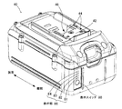
つまり、図2に示すように、二次電池パック40の上部には、本体10の二次電池パック装着部24や、充電器(図示せず)に接続するためのコネクタ部42が形成されている。また、コネクタ部42には、二次電池パック40と電気的に接続するための電源端子部44及び接続端子部46が設けられている。
That is, as shown in FIG. 2, the secondary battery
一方、二次電池パック40は、本体10の二次電池パック装着部24や図示しない充電器の二次電池パック装着部に装着するためのコネクタ部42が形成されたケース(図2参照)内に、コネクタ部42を介して充放電可能な二次電池50を収納したもの(図3参照)である。
On the other hand, the
そして、二次電池パック40は、コネクタ部42を介して本体10に装着することで、コネクタ部42に設けられた電源端子部44及び接続端子部46を介して、本体10の内部回路と電気的に接続され、本体10に直流電源を供給できるようになる(図3参照)。
The
また同様に、二次電池パック40は、コネクタ部42を介して図示しない充電器に装着することで、電源端子部44及び接続端子部46を介して、充電器側の充電回路と電気的に接続され、充電器から二次電池50に充電できるようになる。
Similarly, the
また、図2に示すように、二次電池パック40のケースのコネクタ部42と異なる面(本実施形態では本体10に装着した際、本体10の後方を向く後端面)には、二次電池50の残容量や異常を表示するための表示部86が設けられている。
In addition, as shown in FIG. 2, the
この表示部86は、LEDからなる4つの表示素子81,82,83,84を一列に配置することにより構成されており、その配列方向一端側には、表示部86への残容量若しくは異常状態の表示を指令するための表示スイッチ80が設けられている。
[電動工具本体10の回路構成]
次に、図3は、二次電池パック40を本体10に装着した際に、二次電池パック40と本体10とで形成される駆動モータM1制御用の回路を表す回路図である。
The
[Circuit Configuration of Electric Tool Body 10]
FIG. 3 is a circuit diagram showing a drive motor M1 control circuit formed by the
図3に示すように、本体10には、二次電池パック40の電源端子部44に接続するための端子として、正極側端子32A、負極側端子32Bが備えられ、同じく接続端子部46に接続するための端子として、信号端子34Aが備えられている。
As shown in FIG. 3, the
正極側端子32Aは、メインスイッチSW1及び正極側電源ラインL1Aを介して、駆動モータM1の一端に接続されており、負極側端子32Bは、駆動モータM1への通電制御用のトランジスタQ1及び負極側電源ラインL1Bを介して、駆動モータM1の他端に接続されている。
The
本実施形態では、駆動モータM1は、ブラシ付き直流モータにて構成されており、メインスイッチSW1がオン状態であるとき、トランジスタQ1が二次電池パック40からの入力信号によりオンされることにより、通電されて、回転する。
In the present embodiment, the drive motor M1 is configured by a brushed DC motor, and when the main switch SW1 is in an on state, the transistor Q1 is turned on by an input signal from the
なお、駆動モータM1には、トランジスタQ1のターンオフ時に負極側電源ラインL1Bに発生した高電圧を正極側電源ラインL1Aに戻すためのダイオード(所謂フライホイールダイオード)D1が接続されている。 The drive motor M1 is connected to a diode (so-called flywheel diode) D1 for returning the high voltage generated in the negative power supply line L1B to the positive power supply line L1A when the transistor Q1 is turned off.
また、メインスイッチSW1は、上述したトリガスイッチ22と連動してオン・オフ状態が切り換えられるものであり、トリガスイッチ22が引かれるとメインスイッチSW1がオンし、トリガスイッチ22が放されるとメインスイッチSW1がオフする。
The main switch SW1 is switched on / off in conjunction with the above-described
また、トランジスタQ1には、Nチャネル型MOSFETが用いられている。
次に、本体10には、内部回路駆動用の電源電圧を生成する制御用電源回路36と、二次電池パック40との間で信号を入出力する入出力回路38とが備えられている。
The transistor Q1 is an N-channel MOSFET.
Next, the
制御用電源回路36は、ツェナーダイオードZD1と、コンデンサC1とを備えている。そして、ツェナーダイオードZD1のカソードは、抵抗R1を介して正極側電源ラインL1Aに接続されており、ツェナーダイオードZD1のアノードは、本体10のグランドに接地されている。
The control
また、コンデンサC1は、電解コンデンサからなる。そして、コンデンサC1の正極側は、ツェナーダイオードZD1のカソードとともに、抵抗R1を介して、正極側電源ラインL1Aに接続され、コンデンサC1の負極側は、本体10のグランドに接地されている。
The capacitor C1 is an electrolytic capacitor. The positive side of the capacitor C1 is connected to the positive power supply line L1A through the resistor R1 together with the cathode of the Zener diode ZD1, and the negative side of the capacitor C1 is grounded to the ground of the
なお、本体10のグランドには、負極側端子32Bが接続されており、本体10に二次電池パック40が装着された際には、この負極側端子32Bを介して、二次電池パック40の負極側電源ラインL2B(延いては二次電池50の負極側端子52B)に接続される。
The
また、メインスイッチSW1がオン状態であるとき、正極側電源ラインL1Aには、正極側端子32Aを介して、二次電池パック40の正極側電源ラインL2A(延いては二次電池50の正極側端子52A)に接続される。
Further, when the main switch SW1 is in the on state, the positive power supply line L1A is connected to the positive power supply line L2A of the
従って、制御用電源回路36では、メインスイッチSW1がオンされているときに、正極側電源ラインL1Aから、抵抗R1を介してツェナーダイオードZD1のアノードに二次電池電圧(例えば直流36V)が印加され、ツェナーダイオードZD1によって所定の一定電圧(例えば直流5V)に降圧される。
Therefore, in the control
そして、コンデンサC1は、その降圧された直流電圧により充電され、コンデンサC1の両端電圧は、本体10の内部回路を動作させるための電源電圧Vccとして、各種内部回路に供給される。
The capacitor C1 is charged by the stepped-down DC voltage, and the voltage across the capacitor C1 is supplied to various internal circuits as a power supply voltage Vcc for operating the internal circuit of the
次に、入出力回路38は、トランジスタQ2と、抵抗R2,R3,R4,R5とを備える。
トランジスタQ2は、NPN型バイポーラトランジスタにて構成されており、そのベースは、抵抗R3を介して、信号端子34Aに接続されるとともに、抵抗R4を介して、グランドに接地されている。
Next, the input /
The transistor Q2 is composed of an NPN-type bipolar transistor, and its base is connected to the
また、信号端子34Aには、抵抗R2を介して電源電圧Vccが印加され、トランジスタQ2のコレクタにも、抵抗R5を介して電源電圧Vccが印加されている。また、トランジスタQ2のコレクタは、トランジスタQ1のゲートにも接続されており、トランジスタQ2のエミッタは、グランドに接地されている。
The power supply voltage Vcc is applied to the
抵抗R2,R3,R4の抵抗値は、メインスイッチSW1がオンされてから電源電圧Vccが所定電圧に達したときにトランジスタQ2がオンし、信号端子34Aの電位が電源電圧Vcc近傍のハイレベルになるように設定されている。
The resistance values of the resistors R2, R3, and R4 are such that the transistor Q2 is turned on when the power supply voltage Vcc reaches a predetermined voltage after the main switch SW1 is turned on, and the potential of the
そして、トランジスタQ2がオン状態であるときには、トランジスタQ1のゲートがトランジスタQ2を介してグランドに接地されることから、トランジスタQ1はオフ状態となって、駆動モータM1への通電経路を遮断する。 When the transistor Q2 is in the on state, the gate of the transistor Q1 is grounded to the ground via the transistor Q2, so that the transistor Q1 is in the off state and interrupts the energization path to the drive motor M1.
また、二次電池パック40の内部回路(後述するトランジスタQ4)により、信号端子34Aがグランドに接地されると、トランジスタQ2はオフ状態となる。そして、この状態では、抵抗R5を介してトランジスタQ1のゲートに電源電圧Vccが印加されることから、トランジスタQ1はオン状態となって、駆動モータM1への通電経路を形成する。
Further, when the
なお、本実施形態では、トランジスタQ2のコレクタがトランジスタQ1のゲートに直接接続されるが、トランジスタQ2のコレクタは、トランジスタQ1をスイッチングするための駆動回路を介して、トランジスタQ1のゲートに接続してもよい。
[二次電池パック40の回路構成]
一方、二次電池パック40には、電源端子部44に設けられた正極側端子44A及び負極側端子44Bと、接続端子部46に設けられた3つの信号端子46A,46B,46Cと、二次電池50と、制御回路60とが備えられている。
In this embodiment, the collector of the transistor Q2 is directly connected to the gate of the transistor Q1, but the collector of the transistor Q2 is connected to the gate of the transistor Q1 through a drive circuit for switching the transistor Q1. Also good.
[Circuit Configuration of Secondary Battery Pack 40]
On the other hand, the
正極側端子44Aには、正極側電源ラインL2Aを介して二次電池50の正極側端子52Aが接続され、負極側端子44Bには、負極側電源ラインL2Bを介して二次電池50の負極側端子52Bが接続されている。
The
そして、二次電池パック40を本体10に装着した際、正極側端子44Aは、本体10の正極側端子32Aと接続され、負極側端子44Bは、本体10の負極側端子32Bと接続され、信号端子46Aは、本体10の信号端子34Aに接続される。
When the
なお、信号端子46B,46Cは、二次電池パック40を充電器に装着した際、充電器側の接続端子部に接続されるものであり、二次電池パック40を本体10に装着した際には、開放状態となる。
The
二次電池50は、正極側端子52Aと負極側端子52Bとの間に、複数(例えば10個)の二次電池セルを直列接続することにより構成されており、駆動モータM1を駆動するための駆動電圧(例えば、直流36V)を発生する。
The
なお、二次電池セルは、例えば、単体で3.6Vの直流電圧を発生するリチウムイオン二次電池にて構成される。このため、二次電池50は、高出力可能であり、例えば、出力可能な放電電流は10A以上である。
In addition, the secondary battery cell is configured by, for example, a lithium ion secondary battery that generates a DC voltage of 3.6 V alone. For this reason, the
制御回路60は、電流測定回路62と、電圧測定回路64と、温度測定回路66と、スイッチ操作検出回路68と、充電器検出回路72と、図2に示した表示スイッチ80及び表示部86と、主制御ユニット(Main Control Unit :MCU)70と、トランジスタQ4と、を備えている。
The control circuit 60 includes a
ここで、電流測定回路62は、正極側電源ラインL2A若しくは負極側電源ラインL2Bに流れる電流を検出するためのものであり、その電流に応じた電圧値を有する電流検出信号をMCU70に出力する。
Here, the
また、電圧測定回路64は、二次電池50を構成する各二次電池セルの電圧を順番に測定し、測定電圧に応じた電圧値を有する電圧検出信号をMCU70に出力する。
また、温度測定回路66は、二次電池50周囲に配置されるサーミスタを含み、サーミスタを介して二次電池温度を測定して、その測定温度に応じた電圧値を有する温度検出信号をMCU70に出力する。
Moreover, the
The
次に、スイッチ操作検出回路68は、本体10のトリガスイッチ22が操作されたことを検出するためのものであり、トランジスタQ3と、抵抗R6,R7,R8とを備えている。
Next, the switch
トランジスタQ3は、NPN型バイポーラトランジスタにて構成されており、そのベースは、抵抗R6を介して、信号端子46Aに接続されるとともに、抵抗R7を介して、二次電池パック40におけるグランドに接地されている。また、トランジスタQ3のエミッタは、グランドに接地されている。
The transistor Q3 is composed of an NPN-type bipolar transistor, and its base is connected to the
なお、二次電池パック40のグランドは、負極側電源ラインL2Bに接続されている。このため、二次電池パック40が本体10に装着された際には、二次電池パック40と本体10のグランドが同電位となり、これら各グランドは二次電池50の負極とも同電位になる。
The ground of the
また、トランジスタQ3のコレクタは、MCU70に接続されると共に、抵抗R8を介して、二次電池パック40に設けられた制御用電源回路(図示せず)からの電源電圧Vdd(例えば、直流5V)の出力経路に接続されている。
The collector of the transistor Q3 is connected to the
なお、制御用電源回路は、二次電池50から電源供給を受けて一定の電源電圧Vddを生成し、二次電池パック40内の各種電子回路に電源供給を行うものであり、例えば、スイッチング電源回路等で構成されている。
Note that the control power supply circuit receives power supply from the
一方、トランジスタQ4は、Nチャネル型MOSFETにて構成されており、そのドレインは、トランジスタQ3のベースが抵抗R6を介して接続される信号端子46Aに接続されている。また、トランジスタQ4のソースは、グランドに接地され、トランジスタQ4のゲートは、MCU70に接続されている。
On the other hand, the transistor Q4 is composed of an N-channel MOSFET, and its drain is connected to a
このため、トランジスタQ4は、MCU70からの出力信号(後述する放電制御信号)にてオン・オフされ、トランジスタQ4のオフ時には、信号端子46Aが開放状態となる。
Therefore, the transistor Q4 is turned on / off by an output signal (a discharge control signal described later) from the
従って、二次電池パック40が本体10に装着されて、トリガスイッチ22が操作された際(メインスイッチSW1:オン)、トランジスタQ4がオフ状態であれば、本体10の信号端子34Aから二次電池パック40の信号端子46Aに、二次電池パック40内の電源電圧Vccに対応したハイレベルの信号が入力され、スイッチ操作検出回路68内のトランジスタQ3がオン状態となって、スイッチ操作検出回路68からMCU70への入力信号はローレベルとなる。
Accordingly, when the
また、二次電池パック40が本体10に装着されても、トリガスイッチ22が操作されなければ(メインスイッチSW1:オフ)、本体10の信号端子34Aはローレベル(グランド電位)となるため、スイッチ操作検出回路68内のトランジスタQ3はオフ状態となって、スイッチ操作検出回路68からMCU70への入力信号はハイレベルとなる。
Even if the
次に、充電器検出回路72は、二次電池パック40が充電器に装着されて、充電器から信号端子46Cにハイレベル(例えば直流5V)の信号が入力されたときに、その旨を表す検出信号を入力するものであり、スイッチ操作検出回路68と同様に構成されている。
Next, the
つまり、充電器検出回路72は、信号端子46Cが開放状態にあるときには、プルアップ抵抗を介して、電源電圧Vddに対応したハイレベルの信号をMCU70に入力し、充電器から信号端子46Cにハイレベルの信号が入力されると、MCU70への信号経路に接続されたトランジスタがオン状態となって、信号経路をグランドに接地し、MCU70への出力をローレベルにする。
In other words, when the
このため、MCU70側では、スイッチ操作検出回路68からの入力信号に基づき、二次電池パック40が装着された本体10側でトリガスイッチ22が操作されたことを検知でき、充電器検出回路72からの入力信号に基づき二次電池パック40が充電器に装着されたことを検知できる。
Therefore, on the
また、MCU70は、CPU、ROM、RAM、書換可能な不揮発性メモリ、入出力(I/O)ポート、A/D変換器等からなる周知のマイクロコンピュータにて構成されており、ROMに記憶された各種プログラムに従って二次電池50の充・放電及び状態表示のための各種制御処理を実行する。
[MCU70による表示制御]
次に、このように二次電池パック40内のMCU70にて実行される各種制御処理のうち、二次電池50の残容量や異常を表示するために実行される表示制御処理について、図4に示すフローチャートに沿って説明する。
The
[Display control by MCU 70]
Next, among the various control processes executed by the
この表示制御処理は、MCU70においてメインルーチンの一つとして繰り返し実行される処理であり、処理が開始されると、まずS110にて、電流測定回路62及び電圧測定回路64からの検出信号(換言すれば二次電池50に流れた電流及び二次電池電圧)に基づき二次電池50の残容量を算出する、残容量算出処理を実行する。
This display control process is repeatedly executed as one of the main routines in the
また、続くS120では、電流測定回路62、電圧測定回路64及び温度測定回路66からの検出信号に基づき、下記の(1)〜(5)に示す二次電池50の異常判定を行う。
(1)電流測定回路62にて測定された放電電流が、駆動モータM1のロック時に流れるロック電流に達しているか否かを判定する「ロック電流判定」。
(2)電圧測定回路64にて測定された二次電池電圧が、予め設定された過放電判定用の閾値よりも低下したか否かを判定する「過放電判定」。
(3)電流測定回路62にて測定された放電電流の積算値が過負荷判定用の閾値を超えたか否かを判定する「過負荷判定」。
(4)温度測定回路66にて測定された二次電池温度が予め設定された高温判定用の閾値を超えたか否かを判定する「高温判定」。
(5)電圧測定回路64にて測定された二次電池電圧が正常範囲から外れているか否か等に基づき、二次電池50が故障しているか否かを判定する「故障判定」。
In subsequent S120, based on detection signals from the
(1) “Lock current determination” for determining whether or not the discharge current measured by the
(2) “Overdischarge determination” for determining whether or not the secondary battery voltage measured by the
(3) “Overload determination” for determining whether or not the integrated value of the discharge current measured by the
(4) “High temperature determination” for determining whether or not the secondary battery temperature measured by the
(5) “Failure determination” for determining whether or not the
ここで、上記5つの異常判定結果には、図5に例示するように、その判定結果を表示する際の表示優先度や、表示部86における表示素子81〜84の点灯パターンが予め設定されている。
Here, as illustrated in FIG. 5, display priorities for displaying the determination results and lighting patterns of the
つまり、「ロック電流判定」に伴う異常表示は、表示優先度が最も低く(優先度:1)、その表示パターンは、2個の表示素子81,82を短い周期で点滅(早点滅)させるように設定されている。
That is, the abnormality display associated with the “lock current determination” has the lowest display priority (priority: 1), and the display pattern causes the two
また、「故障判定」に伴う異常表示は、表示優先度が最も高く(優先度:3)、その表示パターンは、4個の表示素子81〜84を、「ロック電流判定」時よりも長い周期で点滅(遅点滅)させるように設定されている。
In addition, the abnormality display accompanying the “failure determination” has the highest display priority (priority: 3), and the display pattern has four
また、「過放電判定」、「過負荷判定」及び「高温判定」に伴う異常表示の表示優先度は、「ロック電流判定」と「故障判定」との間の中間値(優先度:2)に設定されている。 In addition, the display priority of the abnormality display accompanying “overdischarge determination”, “overload determination”, and “high temperature determination” is an intermediate value between “lock current determination” and “failure determination” (priority: 2) Is set to
そして、「過放電判定」の表示パターンは、1個の表示素子81を、「故障判定」時と同じ周期で遅点滅させるように設定され、「過負荷判定」の表示パターンは、2個の表示素子81、82を「故障判定」時と同じ周期で遅点滅させるように設定され、「高温判定」の表示パターンは、3個の表示素子81〜83を「故障判定」時と同じ周期で遅点滅させるように設定されている。
The display pattern of “overdischarge determination” is set so that one
なお、「ロック電流判定」に伴う異常表示と、他の異常判定に伴う異常表示とでは、表示素子の点滅周期が異なるが、これは、駆動モータM1がロック状態となった際には、使用者が操作スイッチとしてのトリガスイッチ22の操作を中止して、メインスイッチSW1をオフさせれば、駆動モータM1のロック状態を解除できるからである。
It should be noted that the blinking cycle of the display element differs between the abnormality display associated with the “lock current determination” and the abnormality display associated with other abnormality determinations. This is used when the drive motor M1 is locked. This is because the locked state of the drive motor M1 can be released if the operator stops the operation of the
つまり、上述の異常判定がなされたときには、MCU70は、二次電池保護のために、放電制御信号をローレベルにして、トランジスタQ4をオフさせることで、本体10のトランジスタQ2をオン状態、トランジスタQ1をオフ状態にして、二次電池50から駆動モータM1への放電を停止させる。
That is, when the above-described abnormality determination is made, the
そして、この保護動作が、「過放電判定」、「過負荷判定」、「高温判定」若しくは「故障判定」に伴い実施されたときには、二次電池パック40が本体10に装着された状態で速やかに正常復帰させることができないことから、異常状態の判定結果は、二次電池パック40が本体10から外され充電器に装着されるまでMCU70のメモリに保存され、異常状態を解除できない。
When this protection operation is performed in conjunction with “overdischarge determination”, “overload determination”, “high temperature determination”, or “failure determination”, the
しかし、「ロック電流判定」による異常は、使用者がトリガスイッチ22の操作を中止して、駆動モータM1のロック状態を解除すれば、速やかに正常復帰することができるため、MCU70は、「ロック電流判定」時には二次電池保護のために二次電池50から駆動モータM1への放電を停止させるものの、その後メインスイッチSW1がオフされると、その保護動作を終了する。
However, the abnormality due to the “lock current determination” can be quickly returned to normal if the user cancels the operation of the
そこで、本実施形態では、このように使用者のスイッチ操作で速やかに正常復帰可能な「ロック電流判定」と、他の異常判定とで、異常表示の際の点滅周期を異なる周期に設定することにより、使用者が、その点滅周期から速やかに正常復帰可能な異常をより簡単に検知できるようにしているのである。 Therefore, in this embodiment, the flashing cycle at the time of abnormality display is set to a different period between the “lock current determination” that can be quickly restored to normal by a user's switch operation and other abnormality determinations. Thus, the user can more easily detect an abnormality that can quickly return to normal from the blinking cycle.
また、二次電池50の残容量表示を行う際の表示素子81〜84の点灯パターンについても、図5に示すように予め設定されている。
つまり、二次電池50の残容量が「0〜25%」のときには、点灯させる表示素子を1個(表示素子81)とし、二次電池50の残容量が「25%〜50%」のときには、点灯させる表示素子を2個(表示素子81、82)とし、二次電池50の残容量が「50%〜75%」のときには、点灯させる表示素子を3個(表示素子81〜83)とし、二次電池50の残容量が「75%〜100%」のときには、全ての表示素子(表示素子81〜84)を点灯させるように設定されている。
Further, the lighting patterns of the
That is, when the remaining capacity of the
次に、S120にて、二次電池50の異常判定が実施されると、今度は、S130に移行して、上記S120にて二次電池50の異常が検出されたか否かを判断する。
そして、上記S120にて二次電池50の異常が検出されていなければ、S140に移行して、二次電池パック40に設けられている表示スイッチ80が使用者により操作(押下)されたか否かを判断する。
Next, when the abnormality determination of the
If no abnormality of the
S140にて、表示スイッチ80は操作(押下)されていないと判断されると、当該表示制御処理を一旦終了し、逆に、表示スイッチ80は操作(押下)されたと判断されると、S150に移行する。
If it is determined in S140 that the
また、S150では、S110にて算出した二次電池50の残容量と、図5に示す表示素子81〜84の点灯パターンを表すデータとに基づき、二次電池50の残容量に対応した表示部86の点灯パターンを設定すると共に、その表示時間として予め設定された残容量表示時間(例えば、3秒)を設定し、S160に移行する。
In S150, the display unit corresponding to the remaining capacity of the
一方、S130にて、二次電池50の異常が検出されていると判断された場合には、S170に移行し、現在、表示部86が表示状態であるか否かを判断する。
そして、S170にて、現在、表示部86が表示状態であると判断されると、S210に移行して、今回検出した異常内容の表示優先度(検出異常優先度)は、現在表示中の表示優先度(表示内容優先度)よりも高いか否かを判断する。
On the other hand, when it is determined in S130 that an abnormality of the
If it is determined in S170 that the
S210にて、今回検出した異常内容の表示優先度が、現在表示中の表示優先度よりも高いと判断された場合には、S200に移行し、今回検出した異常内容の表示優先度が、現在表示中の表示優先度と同じ又は低いと判断された場合には、当該表示制御処理を一旦終了する。 In S210, when it is determined that the display priority of the abnormality content detected this time is higher than the display priority currently being displayed, the process proceeds to S200, and the display priority of the abnormality content detected this time is the current priority. When it is determined that the display priority is the same or lower than the display priority during display, the display control process is temporarily ended.
次に、S170にて、現在、表示部86が表示状態ではないと判断された場合には、S180に移行して、二次電池パック40に設けられている表示スイッチ80が使用者により操作(押下)されたか否かを判断する。
Next, in S170, when it is determined that the
そして、S180にて、表示スイッチ80は操作(押下)されていないと判断されると、S190に移行し、逆に、表示スイッチ80は操作(押下)されたと判断されると、S200に移行する。
If it is determined in S180 that the
S190では、二次電池パック40が装着された本体10側でトリガスイッチ22が操作されて、本体10のメインスイッチSW1がオフ状態からオン状態に切り換えられているか否かを判断する。
In S190, the
そして、S190にて、本体10側のメインスイッチSW1のオフ状態からオン状態への切り換えが判定されなければ、当該表示制御処理を一旦終了し、逆に、本体10側のメインスイッチSW1のオフ状態からオン状態への切り換えが判定された場合には、S200に移行する。
If it is not determined in S190 that the main switch SW1 on the
S200では、S120にて今回検出された二次電池50の異常内容と、図5に示す表示素子81〜84の点灯パターンを表すデータとに基づき、二次電池50の異常内容に対応した表示部86の点灯パターンを設定すると共に、その表示時間として予め設定された異常表示時間(例えば、10秒)を設定し、S160に移行する。
In S200, the display unit corresponding to the abnormality content of the
そして、S160では、S150又はS200で設定された表示部86の点灯パターン及び点灯時間に従い、表示素子81〜84の何れか若しくは全てを、その点灯時間の間、点灯又は点滅させることで、二次電池50の残容量又は異常を表示する、表示素子の点灯処理を起動し、当該表示制御処理を一旦終了する。
[実施形態の効果]
以上説明したように、本実施形態の二次電池パック40には、本体10に装着した際に本体10の後方を向く後端面に、二次電池50の残容量や異常を表示するための表示部86と表示スイッチ80が設けられている。
In S160, according to the lighting pattern and lighting time of the
[Effect of the embodiment]
As described above, in the
そして、表示スイッチ80を操作(押下)すると、二次電池パック40に内蔵されたMCU70が、表示部86を構成する4つの表示素子81〜84の点灯個数を制御することにより、二次電池50の残容量を表示する。
When the
また、MCU70は、二次電池50の残容量だけでなく、二次電池50の各種異常を検出するように構成されており、二次電池50の異常状態を検出しているときに、表示スイッチ80が操作(押下)されるか、或いは、本体10のトリガスイッチ22が操作されると、表示部86を構成する4つの表示素子81〜84を用いて、その検出した異常内容を、残容量の表示よりも優先して表示する。
Further, the
このため、本実施形態の二次電池パック40によれば、異常表示専用の表示装置を設けることなく(換言すれば、二次電池パック40の大型化を招くことなく)、二次電池パック40単体で二次電池50の異常表示を行うことができる。
For this reason, according to the
また、使用者は、電動工具本体10や充電器に二次電池パック40を装着することなく、二次電池50の異常を検知できることから、使用者にとって使い勝手のよい二次電池パックを提供できる。
Further, since the user can detect the abnormality of the
また、二次電池50の残容量や異常状態の表示時間は、予め設定された残容量表示時間若しくは異常表示時間に制限されているので、これらの表示時間を、使用者が表示内容を確認するのに要する時間に制限して、これらの表示によって二次電池50の電力が不必要に消費されるのを防止できる。
In addition, since the remaining capacity of the
また本実施形態では、二次電池50の異常を表示する際には、表示素子81〜84の点灯パターンから、異常内容を識別できるように、異常内容に応じて点灯パターンを設定し、しかも、二次電池パック40を充電器に装着することなく正常復帰し得る「ロック電流」を判定したときには、他の異常判定時とは点滅間隔が異なる点灯パターンを設定するようにされている。
Moreover, in this embodiment, when displaying the abnormality of the
このため、使用者は、点滅している表示素子81〜84の数やその点滅周期から、二次電池50の異常内容を検知でき、しかも、本体10の操作(具体的にはトリガスイッチ22の操作停止)によって速やかに正常復帰し得る異常内容(駆動モータM1のロック)を一目で識別することができるようになる。
For this reason, the user can detect the abnormality content of the
ここで、本実施形態では、図4に示した表示制御処理のS110にて実行される残容量算出処理が、本発明の残容量検出手段に相当し、同じくS140〜S160の一連の処理が、本発明の残容量表示制御手段に相当し、同じくS120にて実行される異常状態検出処理が、本発明の異常検出手段に相当し、同じくS130,S170〜S210及びS160の一連の処理が、本発明の異常表示制御手段に相当し、このうち、S190の処理が、本発明の判定手段に相当する。
[変形例]
以上、本発明の一実施形態について説明したが、本発明は、上記実施形態に限定されるものではなく、本発明の要旨を逸脱しない範囲内にて、種々の態様をとることができる。
Here, in the present embodiment, the remaining capacity calculation process executed in S110 of the display control process shown in FIG. 4 corresponds to the remaining capacity detection means of the present invention, and a series of processes of S140 to S160 are also performed. The abnormal state detection process corresponding to the remaining capacity display control means of the present invention, which is also executed in S120, corresponds to the abnormality detection means of the present invention, and a series of processes of S130, S170 to S210 and S160 are the same. This corresponds to the abnormality display control means of the invention, and among these, the process of S190 corresponds to the determination means of the present invention.
[Modification]
As mentioned above, although one Embodiment of this invention was described, this invention is not limited to the said embodiment, A various aspect can be taken in the range which does not deviate from the summary of this invention.
例えば、上記実施形態では、二次電池50の異常判定として、「ロック電流判定」、「過放電判定」、「過負荷判定」、「高温判定」及び「故障判定」を行うものとして説明したが、二次電池50を構成する各二次電池セルの電圧から二次電池セル毎に異常判定を行う「二次電池セル異常判定」、充電器から二次電池50への過充電により二次電池電圧が正常範囲を超えたことを判定する「過充電判定」、二次電池パック40の内部回路の故障により生じる異常を判定する「制御回路故障判定」等を、更に実施するようにしてもよく、或いは、これら各異常判定の中から選択される複数の異常判定を実施するようにしてもよい。
For example, in the above embodiment, as the abnormality determination of the
また、上記実施形態では、LEDからなる4つの表示素子81〜84の点灯個数や点灯パターンを切り換えることで、二次電池50の残容量及び異常を表示するよう構成された二次電池パック40について説明したが、本発明の二次電池パックは、例えば、点灯時の色を、赤,緑,青というように変更可能な表示素子を1個だけ設け、その表示素子の点灯時の色や点灯状態(点灯・点滅、点滅間隔等)を切り換えることで、二次電池の残容量や異常状態を表示するように構成してもよい。
Moreover, in the said embodiment, about the
また、上記実施形態では、本発明をドライバドリルに適用した場合について説明したが、ドライバドリル以外の電動工具に本願発明を適用してもよい。 Moreover, although the said embodiment demonstrated the case where this invention was applied to a driver drill, you may apply this invention to electric tools other than a driver drill.
10…本体(電動工具本体)、14…モータハウジング、16…ギアハウジング、18…ドリルチャック、20…ハンドグリップ、22…トリガスイッチ、SW1…メインスイッチ、24…二次電池パック装着部、32A…正極側端子、32B…負極側端子、34A…信号端子、36…制御用電源回路、38…入出力回路、L1A…正極側電源ライン、L1B…負極側電源ライン、M1…駆動モータ、Q1…トランジスタ(Nチャネル型MOSFET)、40…二次電池パック、42…コネクタ部、44…電源端子部、44A…正極側端子、44B…負極側端子、46…接続端子部、46A〜46C…信号端子、50…二次電池、52A…正極側端子、52B…負極側端子、60…制御回路、62…電流測定回路、64…電圧測定回路、66…温度測定回路、68…スイッチ操作検出回路、70…MCU、72…充電器検出回路、L2A…正極側電源ライン、L2B…負極側電源ライン、Q4…トランジスタ(Nチャネル型MOSFET)、80…表示スイッチ、81〜84…表示素子(LED)、86…表示部。
DESCRIPTION OF
Claims (6)
外から点灯状態を確認可能に設けられた表示素子と、
二次電池の残容量を検出する残容量検出手段と、
前記表示素子の点灯状態を制御することにより、前記残容量検出手段にて検出された残容量を表示する残容量表示制御手段と、
前記二次電池の異常及び当該二次電池パックが装着された電動工具の異常を検出する異常検出手段と、
前記表示素子の点灯状態を前記残容量表示制御手段による残容量表示とは異なる異常表示状態に制御することで、前記異常検出手段にて検出された異常を表示する異常表示制御手段と、
当該二次電池パックが前記電動工具に装着されたときに前記電動工具の操作スイッチに接続され、該操作スイッチが操作されたか否かを判定する判定手段と、
を備え、
前記異常検出手段は、前記判定手段にて前記電動工具の前記操作スイッチが操作されたと判定されているときに、前記操作スイッチの操作停止によって正常状態に復帰し得る前記電動工具の異常と、当該二次電池パックが前記電動工具に装着された状態で正常復帰させることができない異常と、を検出し、
前記異常表示制御手段は、前記異常検出手段にて検出された異常内容に応じて前記表示素子の点灯パターンを設定することで、前記異常検出手段にて検出された異常を、前記操作スイッチの操作停止によって正常状態に復帰可能な前記電動工具の異常であるか否かを識別可能に表示することを特徴とする二次電池パック。 A secondary battery pack that can be attached to an electric tool,
A display element provided so that the lighting state can be confirmed from the outside,
A remaining capacity detecting means for detecting the remaining capacity of the secondary battery;
A remaining capacity display control means for displaying the remaining capacity detected by the remaining capacity detecting means by controlling the lighting state of the display element;
An abnormality detecting means for detecting an abnormality of the secondary battery and an abnormality of the electric tool mounted with the secondary battery pack;
An abnormality display control means for displaying an abnormality detected by the abnormality detection means by controlling the lighting state of the display element to an abnormality display state different from the remaining capacity display by the remaining capacity display control means;
A determination unit that is connected to an operation switch of the electric tool when the secondary battery pack is attached to the electric tool, and determines whether the operation switch is operated;
With
The abnormality detection means includes an abnormality of the electric tool that can be restored to a normal state by stopping the operation of the operation switch when the determination means determines that the operation switch of the electric tool is operated. An abnormality that cannot be restored to normal with the secondary battery pack attached to the power tool is detected,
The abnormality display control means sets the lighting pattern of the display element according to the abnormality content detected by the abnormality detection means, and thereby detects the abnormality detected by the abnormality detection means. A secondary battery pack characterized by displaying whether or not it is an abnormality of the power tool that can be returned to a normal state by stopping .
前記残容量表示制御手段及び前記異常表示制御手段は、前記表示スイッチからの表示指令に従い前記表示素子の点灯状態を制御し、前記二次電池の残容量若しくは前記異常を表示することを特徴とする請求項1又は請求項2に記載の二次電池パック。 It has a display switch for inputting display commands.
The remaining capacity display control means and the abnormality display control means control a lighting state of the display element in accordance with a display command from the display switch, and display the remaining capacity of the secondary battery or the abnormality. The secondary battery pack according to claim 1 or 2 .
Priority Applications (5)
| Application Number | Priority Date | Filing Date | Title |
|---|---|---|---|
| JP2010240043A JP5662105B2 (en) | 2010-10-26 | 2010-10-26 | Secondary battery pack |
| CN201110303129.6A CN102457081B (en) | 2010-10-26 | 2011-09-28 | Rechargeable battery pack |
| US13/277,469 US8940427B2 (en) | 2010-10-26 | 2011-10-20 | Rechargeable battery pack |
| EP11186366.8A EP2448057B1 (en) | 2010-10-26 | 2011-10-24 | Rechargeable battery pack |
| RU2011143167/07A RU2563965C2 (en) | 2010-10-26 | 2011-10-25 | Battery pack |
Applications Claiming Priority (1)
| Application Number | Priority Date | Filing Date | Title |
|---|---|---|---|
| JP2010240043A JP5662105B2 (en) | 2010-10-26 | 2010-10-26 | Secondary battery pack |
Publications (2)
| Publication Number | Publication Date |
|---|---|
| JP2012095433A JP2012095433A (en) | 2012-05-17 |
| JP5662105B2 true JP5662105B2 (en) | 2015-01-28 |
Family
ID=45346200
Family Applications (1)
| Application Number | Title | Priority Date | Filing Date |
|---|---|---|---|
| JP2010240043A Active JP5662105B2 (en) | 2010-10-26 | 2010-10-26 | Secondary battery pack |
Country Status (5)
| Country | Link |
|---|---|
| US (1) | US8940427B2 (en) |
| EP (1) | EP2448057B1 (en) |
| JP (1) | JP5662105B2 (en) |
| CN (1) | CN102457081B (en) |
| RU (1) | RU2563965C2 (en) |
Families Citing this family (27)
| Publication number | Priority date | Publication date | Assignee | Title |
|---|---|---|---|---|
| US9476825B2 (en) | 2010-10-19 | 2016-10-25 | Baxter International Inc. | Optical imaging system with multiple imaging channel optical sensing |
| JP5938652B2 (en) * | 2012-05-10 | 2016-06-22 | パナソニックIpマネジメント株式会社 | Electric tool |
| DE102012221133A1 (en) * | 2012-11-20 | 2014-05-22 | Robert Bosch Gmbh | Device for testing and maintaining a high-voltage battery and uses of this device |
| JP5998069B2 (en) * | 2013-01-23 | 2016-09-28 | ルネサスエレクトロニクス株式会社 | Semiconductor device and battery pack |
| JP2015050833A (en) * | 2013-08-30 | 2015-03-16 | 日立工機株式会社 | Battery pack, power tool having the same, and charger |
| JP6107562B2 (en) * | 2013-09-19 | 2017-04-05 | 株式会社豊田自動織機 | Battery control unit system |
| JP6344709B2 (en) | 2013-11-12 | 2018-06-20 | パナソニックIpマネジメント株式会社 | Battery pack and electric device including the battery pack |
| JP6195783B2 (en) * | 2013-11-15 | 2017-09-13 | シャープ株式会社 | Battery-powered electronics |
| CN103701163B (en) * | 2013-12-06 | 2018-05-01 | 深圳市大疆创新科技有限公司 | Battery, the aircraft and battery control method with the battery |
| US9592744B2 (en) | 2013-12-06 | 2017-03-14 | SZ DJI Technology Co., Ltd | Battery and unmanned aerial vehicle with the battery |
| JP6294102B2 (en) * | 2014-02-28 | 2018-03-14 | シャープ株式会社 | Battery-powered electronics |
| JP2016022566A (en) * | 2014-07-23 | 2016-02-08 | 株式会社マキタ | Electric machine apparatus |
| JP6514866B2 (en) * | 2014-08-29 | 2019-05-15 | 株式会社マキタ | Rechargeable electric device |
| DE102015218447A1 (en) * | 2014-12-16 | 2016-06-16 | Robert Bosch Gmbh | Battery pack for a hand tool |
| US20160226278A1 (en) * | 2015-02-02 | 2016-08-04 | Black & Decker Inc. | Power tool battery pack and system |
| JP6191796B1 (en) * | 2017-02-10 | 2017-09-06 | ソニー株式会社 | Battery and connected equipment |
| JP6191795B1 (en) * | 2017-02-10 | 2017-09-06 | ソニー株式会社 | Battery and connected equipment |
| JP6796722B2 (en) * | 2017-02-13 | 2020-12-09 | ティティアイ(マカオ コマーシャル オフショアー) リミテッド | Rechargeable battery pack |
| JP6474846B2 (en) * | 2017-03-17 | 2019-02-27 | 株式会社マキタ | Battery pack for electric tools |
| WO2019031273A1 (en) * | 2017-08-09 | 2019-02-14 | 工機ホールディングス株式会社 | Electric device |
| WO2019088264A1 (en) | 2017-11-02 | 2019-05-09 | 株式会社Gsユアサ | Management device, power storage device, cause analysis method, engine driven vehicle, and electric automobile |
| DE102019200527A1 (en) * | 2019-01-17 | 2020-07-23 | Robert Bosch Gmbh | Hand tool |
| US11777171B2 (en) | 2019-01-22 | 2023-10-03 | Yu-Tang Lin | Buckling structure for a battery of a handheld power tool |
| CN110957443A (en) * | 2019-12-11 | 2020-04-03 | 深圳万慧通自动化有限公司 | Monitoring device with forecast battery performance |
| CN114914755B (en) * | 2021-02-10 | 2023-08-11 | 苏州宝时得电动工具有限公司 | Adapter, electrical device system and method of operating the same |
| US11955830B2 (en) | 2021-04-27 | 2024-04-09 | Techtronic Cordless Gp | Battery temperature based tool power reduction |
| CN115674071A (en) * | 2021-07-29 | 2023-02-03 | 株式会社牧田 | Electric tool and impact driver |
Family Cites Families (40)
| Publication number | Priority date | Publication date | Assignee | Title |
|---|---|---|---|---|
| US9028A (en) * | 1852-06-15 | David kood | ||
| JPH037025A (en) * | 1989-06-05 | 1991-01-14 | Hitachi Ltd | Display system of charger |
| JP3438923B2 (en) | 1993-12-13 | 2003-08-18 | 三洋電機株式会社 | Battery pack used for power tools |
| JPH07282858A (en) | 1994-04-12 | 1995-10-27 | Canon Inc | Charging method, charging display method, and battery charger for secondary battery |
| DE29509512U1 (en) | 1995-06-14 | 1996-10-17 | Bosch Gmbh Robert | Battery assembly for a hand machine tool |
| JPH10100079A (en) | 1996-09-30 | 1998-04-21 | Sanyo Electric Co Ltd | Pack battery for power tool |
| US6072299A (en) | 1998-01-26 | 2000-06-06 | Medtronic Physio-Control Manufacturing Corp. | Smart battery with maintenance and testing functions |
| US6084380A (en) | 1998-11-02 | 2000-07-04 | Hewlett-Packard Company | Conforming intelligent battery label |
| US6201370B1 (en) * | 1999-10-01 | 2001-03-13 | Troy M. Reller | Portable power supply |
| JP3743704B2 (en) | 2000-09-25 | 2006-02-08 | Necトーキン栃木株式会社 | Battery pack |
| JP3907950B2 (en) * | 2001-01-18 | 2007-04-18 | 株式会社マキタ | Electric tool |
| US6771043B2 (en) | 2001-05-09 | 2004-08-03 | Makita Corporation | Power tools |
| US7157882B2 (en) | 2002-11-22 | 2007-01-02 | Milwaukee Electric Tool Corporation | Method and system for battery protection employing a selectively-actuated switch |
| US7176654B2 (en) | 2002-11-22 | 2007-02-13 | Milwaukee Electric Tool Corporation | Method and system of charging multi-cell lithium-based batteries |
| US7589500B2 (en) | 2002-11-22 | 2009-09-15 | Milwaukee Electric Tool Corporation | Method and system for battery protection |
| JP3980509B2 (en) | 2003-04-01 | 2007-09-26 | 株式会社マキタ | Secondary battery device |
| US7227335B2 (en) * | 2003-07-22 | 2007-06-05 | Makita Corporation | Method and apparatus for diagnosing the condition of a rechargeable battery |
| CN101916887B (en) | 2003-10-14 | 2013-03-20 | 布莱克和戴克公司 | Battery pack |
| JP4059838B2 (en) * | 2003-11-14 | 2008-03-12 | ソニー株式会社 | Battery pack, battery protection processing device, and control method for battery protection processing device |
| WO2006011938A2 (en) | 2004-05-04 | 2006-02-02 | O2Micro, Inc. | Cordless power tool with a protected weak link element |
| RU2279738C2 (en) * | 2004-08-04 | 2006-07-10 | Военная академия Ракетных войск стратегического назначения им. Петра Великого | Device for determination of power resource of storage batteries |
| JP4318661B2 (en) * | 2005-04-13 | 2009-08-26 | シャープ株式会社 | Portable solar power generator |
| KR20070029883A (en) | 2005-09-12 | 2007-03-15 | 엘지전자 주식회사 | Display device of battery charging state by sense resistor and method |
| DE102005000135A1 (en) | 2005-10-10 | 2007-04-12 | Hilti Ag | Battery pack with charge level indicator |
| JP4618561B2 (en) | 2006-04-28 | 2011-01-26 | 日立工機株式会社 | Battery charger |
| US7639019B2 (en) * | 2007-04-06 | 2009-12-29 | Volkswagen Of America, Inc. | Method and configuration for monitoring a vehicle battery |
| JP4925927B2 (en) * | 2007-06-05 | 2012-05-09 | 三洋電機株式会社 | Battery pack |
| DE102007029747A1 (en) * | 2007-06-27 | 2009-01-08 | Robert Bosch Gmbh | Rechargeable energy supply device for supplying energy to an electrical appliance with a warning signal device |
| EP2015421B1 (en) | 2007-07-13 | 2016-03-09 | Black & Decker, Inc. | Reset mechanism for a battery pack |
| JP5376392B2 (en) | 2008-02-14 | 2013-12-25 | 日立工機株式会社 | Electric tool |
| CN101257273B (en) * | 2008-03-07 | 2010-11-24 | 张志贤 | DC electric machine drive apparatus with power supply by second lithium batteries |
| JP5065958B2 (en) | 2008-03-26 | 2012-11-07 | パナソニック株式会社 | Battery pack |
| US20090289805A1 (en) | 2008-05-23 | 2009-11-26 | Patrick Robert A | Device With Window For Viewing Fuel Gauge On Battery |
| US8269458B2 (en) | 2008-10-07 | 2012-09-18 | Black & Decker Inc. | Shared control of thermistor and dual purpose thermistor line |
| DE102009012178B4 (en) | 2009-02-27 | 2019-07-04 | Andreas Stihl Ag & Co. Kg | Battery operated, handheld implement |
| DE102009012184A1 (en) | 2009-02-27 | 2010-09-02 | Andreas Stihl Ag & Co. Kg | Portable, hand-held electrical appliance with a battery pack |
| DE102009012183A1 (en) | 2009-02-27 | 2010-09-02 | Andreas Stihl Ag & Co. Kg | Battery pack for a hand-held implement |
| DE102009012176A1 (en) | 2009-02-27 | 2010-09-02 | Andreas Stihl Ag & Co. Kg | Battery pack with monitoring electronics integrated in the housing cover |
| JP5324977B2 (en) * | 2009-03-26 | 2013-10-23 | パナソニック株式会社 | Electric tool |
| JP5475490B2 (en) * | 2010-02-05 | 2014-04-16 | 株式会社マキタ | Electric tool and program |
-
2010
- 2010-10-26 JP JP2010240043A patent/JP5662105B2/en active Active
-
2011
- 2011-09-28 CN CN201110303129.6A patent/CN102457081B/en active Active
- 2011-10-20 US US13/277,469 patent/US8940427B2/en active Active
- 2011-10-24 EP EP11186366.8A patent/EP2448057B1/en active Active
- 2011-10-25 RU RU2011143167/07A patent/RU2563965C2/en active
Also Published As
| Publication number | Publication date |
|---|---|
| CN102457081B (en) | 2015-04-22 |
| JP2012095433A (en) | 2012-05-17 |
| RU2011143167A (en) | 2013-04-27 |
| CN102457081A (en) | 2012-05-16 |
| EP2448057B1 (en) | 2020-05-13 |
| RU2563965C2 (en) | 2015-09-27 |
| US20120100405A1 (en) | 2012-04-26 |
| US8940427B2 (en) | 2015-01-27 |
| EP2448057A1 (en) | 2012-05-02 |
Similar Documents
| Publication | Publication Date | Title |
|---|---|---|
| JP5662105B2 (en) | Secondary battery pack | |
| US9203249B2 (en) | Battery pack for electric power tool, control circuit, and program | |
| JP5524694B2 (en) | Device for estimating calorific value of power tool battery and power tool device | |
| JP5579046B2 (en) | Electric tool equipment | |
| JP5554622B2 (en) | Electric tool equipment | |
| JP5270380B2 (en) | Electric tool, electric tool body, and battery pack | |
| EP2246157B1 (en) | Electric power tool, tool body, and battery pack | |
| EP2905866B1 (en) | Electrically-driven working apparatus and battery therefor. | |
| US9466860B2 (en) | Battery pack | |
| CN107848102B (en) | Hand-held electric tool | |
| JP3128990U (en) | Electric tool | |
| JP4103828B2 (en) | Rechargeable electrical equipment | |
| EP2963756B1 (en) | Electric power tool | |
| JP4103882B2 (en) | Rechargeable electrical equipment | |
| JP7056755B2 (en) | Battery pack and electrical equipment using it | |
| JP6642797B2 (en) | Control circuit, battery pack and power tool | |
| JP2012119109A (en) | Battery pack |
Legal Events
| Date | Code | Title | Description |
|---|---|---|---|
| A621 | Written request for application examination |
Free format text: JAPANESE INTERMEDIATE CODE: A621 Effective date: 20130426 |
|
| A977 | Report on retrieval |
Free format text: JAPANESE INTERMEDIATE CODE: A971007 Effective date: 20140219 |
|
| A131 | Notification of reasons for refusal |
Free format text: JAPANESE INTERMEDIATE CODE: A131 Effective date: 20140225 |
|
| A521 | Request for written amendment filed |
Free format text: JAPANESE INTERMEDIATE CODE: A523 Effective date: 20140425 |
|
| A131 | Notification of reasons for refusal |
Free format text: JAPANESE INTERMEDIATE CODE: A131 Effective date: 20140722 |
|
| A521 | Request for written amendment filed |
Free format text: JAPANESE INTERMEDIATE CODE: A523 Effective date: 20140922 |
|
| TRDD | Decision of grant or rejection written | ||
| A01 | Written decision to grant a patent or to grant a registration (utility model) |
Free format text: JAPANESE INTERMEDIATE CODE: A01 Effective date: 20141111 |
|
| A61 | First payment of annual fees (during grant procedure) |
Free format text: JAPANESE INTERMEDIATE CODE: A61 Effective date: 20141204 |
|
| R150 | Certificate of patent or registration of utility model |
Ref document number: 5662105 Country of ref document: JP Free format text: JAPANESE INTERMEDIATE CODE: R150 |
|
| R250 | Receipt of annual fees |
Free format text: JAPANESE INTERMEDIATE CODE: R250 |
|
| R250 | Receipt of annual fees |
Free format text: JAPANESE INTERMEDIATE CODE: R250 |
|
| R250 | Receipt of annual fees |
Free format text: JAPANESE INTERMEDIATE CODE: R250 |
|
| R250 | Receipt of annual fees |
Free format text: JAPANESE INTERMEDIATE CODE: R250 |
|
| R250 | Receipt of annual fees |
Free format text: JAPANESE INTERMEDIATE CODE: R250 |
|
| R250 | Receipt of annual fees |
Free format text: JAPANESE INTERMEDIATE CODE: R250 |
|
| R250 | Receipt of annual fees |
Free format text: JAPANESE INTERMEDIATE CODE: R250 |