JP5660242B1 - Communication system, communication control system, communication apparatus, communication method, and connection program - Google Patents
Communication system, communication control system, communication apparatus, communication method, and connection program Download PDFInfo
- Publication number
- JP5660242B1 JP5660242B1 JP2014114311A JP2014114311A JP5660242B1 JP 5660242 B1 JP5660242 B1 JP 5660242B1 JP 2014114311 A JP2014114311 A JP 2014114311A JP 2014114311 A JP2014114311 A JP 2014114311A JP 5660242 B1 JP5660242 B1 JP 5660242B1
- Authority
- JP
- Japan
- Prior art keywords
- communication device
- setting
- network identifier
- communication
- network
- Prior art date
- Legal status (The legal status is an assumption and is not a legal conclusion. Google has not performed a legal analysis and makes no representation as to the accuracy of the status listed.)
- Expired - Fee Related
Links
Images


Classifications
-
- H—ELECTRICITY
- H04—ELECTRIC COMMUNICATION TECHNIQUE
- H04W—WIRELESS COMMUNICATION NETWORKS
- H04W36/00—Hand-off or reselection arrangements
- H04W36/14—Reselecting a network or an air interface
-
- H—ELECTRICITY
- H04—ELECTRIC COMMUNICATION TECHNIQUE
- H04W—WIRELESS COMMUNICATION NETWORKS
- H04W8/00—Network data management
- H04W8/005—Discovery of network devices, e.g. terminals
-
- H—ELECTRICITY
- H04—ELECTRIC COMMUNICATION TECHNIQUE
- H04B—TRANSMISSION
- H04B17/00—Monitoring; Testing
- H04B17/30—Monitoring; Testing of propagation channels
- H04B17/309—Measuring or estimating channel quality parameters
-
- H—ELECTRICITY
- H04—ELECTRIC COMMUNICATION TECHNIQUE
- H04W—WIRELESS COMMUNICATION NETWORKS
- H04W4/00—Services specially adapted for wireless communication networks; Facilities therefor
- H04W4/60—Subscription-based services using application servers or record carriers, e.g. SIM application toolkits
-
- H—ELECTRICITY
- H04—ELECTRIC COMMUNICATION TECHNIQUE
- H04W—WIRELESS COMMUNICATION NETWORKS
- H04W48/00—Access restriction; Network selection; Access point selection
- H04W48/16—Discovering, processing access restriction or access information
-
- H—ELECTRICITY
- H04—ELECTRIC COMMUNICATION TECHNIQUE
- H04W—WIRELESS COMMUNICATION NETWORKS
- H04W76/00—Connection management
- H04W76/10—Connection setup
-
- H—ELECTRICITY
- H04—ELECTRIC COMMUNICATION TECHNIQUE
- H04W—WIRELESS COMMUNICATION NETWORKS
- H04W84/00—Network topologies
- H04W84/02—Hierarchically pre-organised networks, e.g. paging networks, cellular networks, WLAN [Wireless Local Area Network] or WLL [Wireless Local Loop]
- H04W84/10—Small scale networks; Flat hierarchical networks
- H04W84/12—WLAN [Wireless Local Area Networks]
-
- H—ELECTRICITY
- H04—ELECTRIC COMMUNICATION TECHNIQUE
- H04W—WIRELESS COMMUNICATION NETWORKS
- H04W92/00—Interfaces specially adapted for wireless communication networks
- H04W92/04—Interfaces between hierarchically different network devices
- H04W92/08—Interfaces between hierarchically different network devices between user and terminal device
-
- H—ELECTRICITY
- H04—ELECTRIC COMMUNICATION TECHNIQUE
- H04W—WIRELESS COMMUNICATION NETWORKS
- H04W92/00—Interfaces specially adapted for wireless communication networks
- H04W92/16—Interfaces between hierarchically similar devices
- H04W92/18—Interfaces between hierarchically similar devices between terminal devices
Abstract
【課題】 通信装置間の無線接続を迅速に行うことができるようにする。【解決手段】 表示装置A(110)と情報端末120とを有する通信システムであって、表示装置A(110)は、表示装置A(110)と情報端末120とのの間の無線通信に用いられる設定情報が格納された設定テーブルを特定する特定情報を含むSSID(A)を生成する手段と、前記生成されたSSID(A)をビーコンに含めて送信する手段と、を有し、情報端末120は、受信したビーコンのうち、SSIDに前記特定情報が含まれ、かつ、受信強度が所定の条件を満たすビーコンを識別する手段と、前記識別したビーコンのSSID(A)に含まれる前記特定情報により特定される設定テーブルを用いて、表示装置A(110)と情報端末120との間の無線通信に用いられる前記設定情報を情報端末120に設定する手段とを有することを特徴とする。【選択図】図5PROBLEM TO BE SOLVED: To quickly perform wireless connection between communication devices. A communication system including a display device A (110) and an information terminal 120, the display device A (110) being used for wireless communication between the display device A (110) and the information terminal 120. Means for generating an SSID (A) including specific information for specifying a setting table in which the setting information is stored, and means for transmitting the generated SSID (A) in a beacon, and an information terminal 120 is a means for identifying a beacon in which the specific information is included in an SSID and a reception intensity satisfies a predetermined condition among the received beacons, and the specific information included in the SSID (A) of the identified beacon. Means for setting the setting information used for wireless communication between the display device A (110) and the information terminal 120 in the information terminal 120 using the setting table specified by It is characterized by having. [Selection] Figure 5
Description
本発明は、無線接続技術に関するものであり、特に、通信システム、通信制御システム、通信装置、通信方法及び接続プログラムに関するものである。 The present invention relates to a wireless connection technology, and more particularly to a communication system, a communication control system, a communication device, a communication method, and a connection program.
従来より、電子装置同士をネットワークにより無線接続し、データの送受信を行うための様々なシステムが知られている。 Conventionally, various systems for wirelessly connecting electronic devices to each other via a network and transmitting and receiving data are known.
一般にネットワークを介してデータを送受信するためには、接続側の通信装置が、接続先となるネットワークを特定し、無線通信に必要な設定(例えば、IPアドレス、サブネットマスク、認証方式、暗号方式、暗号鍵等の設定)を行う必要がある。しかしながら、ユーザにとってこれらの設定を行うことは容易ではなく、また、接続が完了するまでに一定程度の時間がかかるといった問題がある。このため、従来より、ネットワークに迅速に無線接続し、かつ、ユーザの接続操作を容易にするための種々の提案がなされている。 In general, in order to transmit and receive data via a network, a communication device on the connection side specifies a network to be connected to and sets necessary for wireless communication (for example, IP address, subnet mask, authentication method, encryption method, It is necessary to set the encryption key. However, it is not easy for the user to make these settings, and there is a problem that it takes a certain amount of time to complete the connection. For this reason, conventionally, various proposals have been made for quickly wirelessly connecting to a network and facilitating a user's connection operation.
例えば、特許文献1及び特許文献2では、被接続側の通信装置が、自装置のIPアドレスと個体識別子(例えば、装置の名前)とを記載したSSID(Service Set Identifier)を生成し、当該SSIDをビーコンに含めて送信する構成が提案されてきた。
For example, in
当該文献によれば、接続側の通信装置が、受信したビーコンに含まれる情報に基づいて無線通信に必要な設定を行うことができるため、接続操作が容易になるといった利点がある。また、接続側の通信装置が、接続先となるネットワークを検索するためのスキャンを行う必要がないため、スキャン時間を短縮できるといった利点もある。 According to the said literature, since the communication apparatus of the connection side can perform a setting required for wireless communication based on the information contained in the received beacon, there exists an advantage that connection operation becomes easy. In addition, there is an advantage that the scan time can be shortened because the communication device on the connection side does not need to perform a scan for searching for a network as a connection destination.
しかしながら、上記特許文献1及び2の場合、接続側の通信装置で設定した設定内容を、被接続側の通信装置に送信し、被接続側の通信装置で、当該設定内容による通信が可能か否かを判断する必要があった。このため、接続側の通信装置で無線通信に必要な設定が行われてから、実際にデータの送受信が開始されるまでに時間がかかるといった問題があった。
However, in the case of
本発明は、上記事情に鑑みてこれを解決すべくなされたものであり、通信装置間の無線接続を迅速に行うことができるようにすることを目的とする。 The present invention has been made in view of the above circumstances, and an object of the present invention is to enable quick wireless connection between communication devices.
本発明は、上記目的を達成すべく以下の如き構成を採用した。即ち、
第1の通信装置と第2の通信装置とを有する通信システムであって、
前記第1の通信装置は、
前記第1の通信装置と前記第2の通信装置との間の無線通信に用いられる設定情報が格納された設定テーブルを特定する特定情報と前記第1の通信装置に個別に付けられた個体識別子とを含むネットワーク識別子を生成する生成手段と、
前記生成手段により生成されたネットワーク識別子を含むビーコン信号を送信する送信手段と、を有し、
前記第2の通信装置は、
受信したビーコン信号から取得したネットワーク識別子のうち、前記特定情報が含まれ、かつ、受信したビーコン信号の受信強度が所定の条件を満たすネットワーク識別子を識別する識別手段と、
前記識別したネットワーク識別子に含まれる前記特定情報により特定される設定テーブルを用いて、前記識別したネットワーク識別子に基づいて特定されるネットワークを形成する前記第1の通信装置との間の無線通信に用いられる設定情報を前記第2の通信装置に設定する設定手段とを有することを特徴とする。
The present invention employs the following configuration in order to achieve the above object. That is,
A communication system having a first communication device and a second communication device,
The first communication device is:
Specific information for specifying a setting table in which setting information used for wireless communication between the first communication device and the second communication device is stored, and an individual identifier individually assigned to the first communication device a generating means for generating a network identifier that includes bets,
Transmitting means for transmitting a beacon signal including the network identifier generated by the generating means,
The second communication device is:
Of the network identifier acquired from the received beacon signal, the specific information includes, and the reception intensity of the received beacon signal identifying means for identifying a predetermined condition is satisfied network identifier,
Using a setting table which is specified by the specifying information included in the identified network identifier, used for wireless communication with the identified first communication device forming a network which is specified on the basis of the network identifier And setting means for setting the setting information to be set in the second communication device.
本発明の実施形態によれば、通信装置間の無線接続を迅速に行うことができるようになる。 According to the embodiment of the present invention, wireless connection between communication devices can be performed quickly.
以下、図面を参照しながら、本発明の各実施形態について説明する。なお、以下の各実施形態に係る無線接続技術は、例えば、情報端末と表示装置とを有する再生システムにおいて実現される。具体的には、情報端末が、コンテンツデータの再生に関する情報である再生制御情報を生成し、コンテンツデータとともに表示装置に送信することで、表示装置にて当該再生制御情報に基づきコンテンツデータの再生を行う再生システムにおいて実現される。 Hereinafter, embodiments of the present invention will be described with reference to the drawings. Note that the wireless connection technology according to each of the following embodiments is realized, for example, in a reproduction system including an information terminal and a display device. Specifically, the information terminal generates reproduction control information that is information related to reproduction of content data, and transmits the reproduction control information together with the content data to the display device, whereby the display device reproduces the content data based on the reproduction control information. Realized in a playback system to perform.
つまり、以下で説明する再生システムは、本発明に係る通信システムの一例であり、該再生システムを構成する情報端末及び表示装置は、本発明に係る通信装置の一例である。また、表示装置と情報端末の接続プログラムとを有する再生制御システムは、本発明に係る通信制御システムの一例である。 That is, the reproduction system described below is an example of a communication system according to the present invention, and the information terminal and the display device that constitute the reproduction system are examples of the communication apparatus according to the present invention. A reproduction control system having a display device and an information terminal connection program is an example of a communication control system according to the present invention.
以下、当該再生システムならびに当該再生システムを構成する情報端末及び表示装置について詳説したうえで、当該再生システムにおいて実現される各実施形態の無線接続技術の詳細について説明する。 In the following, the reproduction system and the information terminal and display device constituting the reproduction system will be described in detail, and the details of the wireless connection technology of each embodiment realized in the reproduction system will be described.
[第1の実施形態]
<再生システムのシステム構成>
はじめに、本実施形態に係る無線接続技術が実現される再生システムのシステム構成について説明する。図1は、本実施形態に係る無線接続技術が実現される再生システム100のシステム構成の一例を示す図である。
[First Embodiment]
<System configuration of playback system>
First, the system configuration of a playback system that realizes the wireless connection technology according to the present embodiment will be described. FIG. 1 is a diagram illustrating an example of a system configuration of a
再生システム100は、本実施形態に係る通信装置の一例である情報端末120と表示装置110とを有する。再生システム100において、情報端末120と表示装置110とはネットワーク等のデータ伝送路Nを介して通信可能に接続される。
The
情報端末120は、例えば3G(3rd Generation)、LTE(Long Term Evolution)、4G(4th Generation)等の規格に準ずる通信方式により通信を行うよう構成されている。ただし、情報端末120は、例えばZigBee(登録商標)やBluetooth(登録商標)等に準ずる通信方式により通信を行うよう構成されていてもよい。
The
情報端末120は、例えばスマートフォンや携帯電話等の無線通信端末であっても、あるいはタブレットPC(Personal Computer)やノート型PCであってもよく、表示装置110と通信を行うことができる機器であれば何でもよい。
The
情報端末120には、本実施形態に係る接続プログラム(接続側)121と再生制御プログラム122とがインストールされている。情報端末120は、接続プログラム(接続側)121を実行することにより、表示装置110と無線接続する。また、表示装置110と無線接続された状態で、再生制御プログラム122を実行することにより、表示装置110に表示するコンテンツデータについて再生制御情報を生成し、コンテンツデータとともに表示装置110に送信する。
A connection program (connection side) 121 and a
表示装置110には、接続プログラム(被接続側)111と再生プログラム112とがインストールされている。表示装置110が、接続プログラム(被接続側)111を実行することにより、情報端末120では、無線通信に必要な設定を行うことが可能になる。また、再生プログラム112を実行することにより、情報端末120から送信されたコンテンツデータを、再生制御情報に基づいて再生することができる。
In the
なお、表示装置110は、情報端末120から送信された再生制御情報に基づきコンテンツデータを表示する表示機能を有していればよく、例えばプロジェクタやディスプレイ等の機器であればよい。
The
なお、本実施形態の説明では、表示装置110が再生制御情報にしたがってコンテンツデータを表示することを、コンテンツデータを再生する、と表現する。
In the description of the present embodiment, displaying the content data according to the reproduction control information by the
また、本実施形態の説明におけるコンテンツデータには、例えば、画像(静止画)データや動画データ等が含まれる。また、コンテンツデータとなる画像データは、例えば1枚の画像からなる画像データであってもよいし、複数枚の画像からなる画像データ群であってもよい。すなわち、本実施形態の説明におけるコンテンツデータは、表示装置110にて再生させることが可能なデータであれば何でもよい。
The content data in the description of the present embodiment includes, for example, image (still image) data, moving image data, and the like. Further, the image data serving as content data may be, for example, image data composed of a single image, or may be an image data group composed of a plurality of images. That is, the content data in the description of the present embodiment may be anything as long as it can be reproduced by the
なお、以下の各実施形態の説明では、表示装置110にて再生されるコンテンツデータを再生コンテンツデータと呼び、それ以外の、例えば所定の記憶領域に格納されているコンテンツデータを単にコンテンツデータと呼ぶ。
In the following description of each embodiment, content data reproduced on the
<再生システムの利用シーンの説明>
次に、図2を参照しながら、再生システム100の利用シーンについて説明する。図2は、再生システム100の利用シーンの一例を説明する図である。
<Description of playback system usage scenes>
Next, a usage scene of the
図2の例では、情報端末120としてスマートフォン又はタブレットPCを用い、表示装置110としてプロジェクタ211とスクリーン212とを用いた再生システム100が示されている。なお、当該再生システム100は、例えば電子看板(Digital Signage)として利用することができる。
In the example of FIG. 2, a
情報端末120では、ユーザにより、コンテンツデータが選択されると、再生コンテンツデータを生成する。また、再生コンテンツデータの再生方法が設定されると、この設定に基づき、再生コンテンツデータについての再生制御情報を生成する。そして情報端末120では、再生コンテンツデータと再生制御情報とをプロジェクタ211に送信する。プロジェクタ211では、受信した再生コンテンツデータを記憶部312(後述)に格納し、再生制御情報に従って再生コンテンツデータを再生する。
When the content data is selected by the user, the
このように、再生システム100によれば、ユーザは、再生コンテンツデータと再生制御情報とを、1度、情報端末120から表示装置110に送信すれば、表示装置110において当該再生コンテンツデータを所望の設定通りに継続して再生させることができる。
As described above, according to the
すなわち、再生システム100を電子看板等に利用した場合、所望する再生コンテンツデータが自動的に再生されるため、ユーザは再生コンテンツデータの表示順序や表示の切り替え等に関する設定を、その都度行う必要がなくなる。
That is, when the
<再生システムのハードウェア構成>
次に図3を参照して再生システム100が有する各装置のハードウェア構成を説明する。図3は、再生システム100が有する各装置(表示装置110、情報端末120)のハードウェア構成の一例を示す図である。
<Hardware configuration of playback system>
Next, the hardware configuration of each device included in the
情報端末120は、CPU(Central Processing Unit)321、記憶部322、入力部323、外部インタフェース部324、ネットワーク制御部325、出力部326、ドライバ327を有する。なお、これらの要素はバスB2を介して相互に接続されている。
The
CPU321は、情報端末120の各種動作を制御するコンピュータである。記憶部322は、情報端末120の動作や演算に係る各種情報、情報端末120で実行される、接続プログラム(接続側)121、再生制御プログラム122をはじめとする各種プログラム等を格納する。入力部323は、各種信号や情報を入力するために用いられる。入力部323は、例えばタッチパネル等の表示機能を有していてもよい。また、入力部323は、例えばポインティングデバイスやキーボード等であってもよい。
The
外部インタフェース部324は、例えばUSB(Universal Serial Bus)メモリスロットやNFC(Near field communication)等である。ネットワーク制御部325は、モデム、LANカード等を含み、ネットワークに無線接続し、無線通信を行うのに用いられる。
The
出力部326は、情報端末120から外部に各種情報を出力するために用いられる。出力部326は、例えばディスプレイ等であってもよいし、外部装置へ各種データを送信する送信部であってもよい。
The
なお、本実施形態に係る接続プログラム(接続側)121及び再生制御プログラム122は、情報端末120を制御する各種プログラムの少なくとも一部であり、例えば、記録媒体328の配布やネットワークからのダウンロードなどによって提供される。
The connection program (connection side) 121 and the
ここで、接続プログラム(接続側)121及び再生制御プログラム122が格納された記録媒体328は、表示装置110と組み合わせ、再生制御システムとしてユーザに提供されうる。あるいは、表示装置110とは別個にユーザに提供されてもよい。つまり、接続プログラム(接続側)121及び再生制御プログラム122が格納された記録媒体328のみが単独でユーザに提供されてもよい。あるいは接続プログラム(接続側)121及び再生制御プログラムのみが単独でダウンロードされることでユーザに提供されてもよい。無論、情報端末120にはじめからインストールされた状態で、情報端末120として、ユーザに提供されてもよい。
Here, the
接続プログラム(接続側)121及び再生制御プログラム122を記録した記録媒体328には、CD−ROM、フレキシブルディスク、光磁気ディスク等のように情報を光学的,電気的或いは磁気的に記録する記録媒体を用いることができる。あるいは、ROM、フラッシュメモリ等のように情報を電気的に記録する半導体メモリ等の記録媒体を用いることができる。
The
接続プログラム(接続側)121及び再生制御プログラム122を記録した記録媒体328がドライバ327にセットされると、接続プログラム(接続側)121及び再生制御プログラム122は記録媒体328から記憶部322にインストールされる。ネットワークからダウンロードされる場合にあっては、接続プログラム(接続側)121及び再生制御プログラム122は、ネットワーク制御部325を介して記憶部322にインストールされる。
When the
記憶部322は、インストールされた接続プログラム(接続側)121及び再生制御プログラム122をはじめとする各種プログラムを格納すると共に、必要なファイル、データ等を格納する。CPU321は記憶部322に格納された接続プログラム(接続側)121及び再生制御プログラム122に従って、後述するような各種処理(接続処理等)を実現する。
The
表示装置110は、それぞれがバスB1を介して相互に接続されているCPU311、記憶部312、入力部313、外部インタフェース部314、ネットワーク制御部315、表示部316、ドライバ317を有する。
The
CPU311は、表示装置110の各種動作を制御するコンピュータである。記憶部312は、表示装置110の動作や演算に係る各種情報や、表示装置110で実行される接続プログラム(被接続側)111及び再生プログラム112をはじめとする各種プログラムや、表示装置110で再生される再生コンテンツデータ等を格納する。入力部313は、各種信号や情報を入力するために用いられる。入力部313は、例えば表示装置110を操作する操作部材等である。
The
外部インタフェース部314は、例えば、USB(Universal Serial Bus)メモリスロットやNFC(Near field communication)等である。ネットワーク制御部315は、例えば、表示装置110と情報端末120との無線通信を制御する。表示部316は、表示装置110が再生指示を受けた再生コンテンツデータを再生する。
The
接続プログラム(被接続側)111及び再生プログラム112は、表示装置110を制御する各種プログラムの少なくとも一部である。接続プログラム(被接続側)111及び再生プログラム112は、例えば、記録媒体318の配布やネットワークからのダウンロードなどによって提供される。
The connection program (connected side) 111 and the
接続プログラム(被接続側)111及び再生プログラム112を記録した記録媒体318がドライバ317にセットされると、接続プログラム(被接続側)111及び再生プログラム112は記録媒体318から記憶部312にインストールされる。また、ネットワークからダウンロードされた場合にあっては、接続プログラム(被接続側)111及び再生プログラム112は、ネットワーク制御部315を介して記憶部312にインストールされる。
When the
記憶部312は、インストールされた接続プログラム(被接続側)111及び再生プログラム112を格納するとともに、必要なファイルや再生コンテンツデータ等のデータを格納する。CPU311は記憶部312に格納された接続プログラム(被接続側)111及び再生プログラム112に従って、後述するような各種処理(接続処理等)を実現する。
The
<再生システムにおける無線接続に関する機能構成>
次に、図4を参照して、再生システム100が有する各装置(表示装置110、情報端末120)の無線接続に関する機能構成について説明する。図4は、再生システム100が有する各装置(表示装置110、情報端末120)の無線接続に関する機能構成の一例を示す図である。
<Functional configuration related to wireless connection in playback system>
Next, with reference to FIG. 4, a functional configuration related to wireless connection of each device (
図4(a)は、表示装置110の無線接続に関する機能として、表示装置110が有する接続プログラム(被接続側)111がCPU311によって実行されることで実現される機能を示している。
FIG. 4A shows functions realized by the
図4(a)に示すように、表示装置110は、ユーザ操作部411、無線設定保持部412、接続制御部413、SSID生成部414、識別子生成部415を備える。
As illustrated in FIG. 4A, the
ユーザ操作部411は、無線接続するための各種操作をユーザから受け付ける。本実施形態では、表示装置110の電源がオンされると、接続プログラム(被接続側)111が起動するよう構成されており、ユーザ操作部411では、表示装置110の電源オン操作を受け付ける。
The
無線設定保持部412は、表示装置110が情報端末120と無線通信する場合に、表示装置110に設定される設定情報が格納された設定テーブル431を保持する。なお、設定テーブルの詳細は後述する。
The wireless
接続制御部413は、情報端末120が無線接続できるように、ビーコン(少なくともネットワーク識別子を含む信号)の生成ならびに送信を制御するとともに、無線設定保持部412に保持された設定テーブル431の設定情報を、表示装置110内に設定する。
The
SSID生成部414は、ビーコンに含めるSSID(Service Set Identifier)を生成する(詳細は後述)。ここで、SSIDとは、ネットワークを識別するネットワーク識別子であり、アドホックモード(アクセスポイントを介さない通信を行うモード)においては、それぞれの通信装置間で共通のSSIDが設定される。
The
識別子生成部415は、SSIDに記載される製品識別子と個体識別子とを生成する。製品識別子とは、表示装置110の製品種類を示す識別子である。同じ製品識別子を有する表示装置は、同じ製品種類の表示装置であることを示しており、(別体であっても)同じ接続プログラム(被接続側)111が動作し、無線通信する際には、同じ設定テーブル431が用いられる。
The
つまり、同じ接続プログラム(被接続側)111が動作し同じ設定テーブルが用いられる表示装置では、同じ製品識別子が生成される。なお、ここでは、接続プログラム(被接続側)111が、製品種類ごとに異なることを前提としているため、製品識別子を表示装置110の製品種類を示す識別子として定義した。しかしながら、本発明はかかる前提に限定されない。
That is, in the display device in which the same connection program (connected side) 111 operates and the same setting table is used, the same product identifier is generated. Here, since it is assumed that the connection program (connected side) 111 is different for each product type, the product identifier is defined as an identifier indicating the product type of the
接続プログラム(被接続側)111が表示装置の製品種類とは無関係にインストールされる場合にあっては、接続プログラム(被接続側)111の製品種類を示す識別子であってもよい。いずれにしても、表示装置110では、無線通信において同じ設定テーブルが用いられる場合には、同じ製品識別子が生成されるよう構成されており、製品識別子は、設定テーブルと1:1に対応付けられている。このため、製品識別子は、設定テーブルを特定するための特定情報ということができる。
If the connection program (connected side) 111 is installed regardless of the product type of the display device, an identifier indicating the product type of the connection program (connected side) 111 may be used. In any case, the
一方、個体識別子とは、装置ごとに個別に付けられた固有情報からなる識別子である。個体識別子は、製品種類が同じであるか否かに関わらず、別体の装置であれば、異なる値となる。なお、ここでいう固有情報には、例えば、装置の製造番号やMACアドレス等が含まれる。 On the other hand, the individual identifier is an identifier composed of unique information individually assigned to each device. The individual identifiers have different values for different devices regardless of whether the product types are the same. Here, the unique information includes, for example, a device manufacturing number and a MAC address.
図4(b)は、情報端末120の無線接続に関する機能として、情報端末120が有する接続プログラム(接続側)121がCPU321によって実行されることで実現される機能を示している。
FIG. 4B illustrates a function realized by the
図4(b)に示すように、情報端末120は、ユーザ操作部421、無線設定保持部422、接続制御部423、表示制御部424、SSID解析部425、識別子判定部426、受信強度判定部427を備える。
As shown in FIG. 4B, the
ユーザ操作部421は、無線接続するための各種操作をユーザから受け付ける。本実施形態では、情報端末120の電源オン操作や、再生制御プログラム122の起動操作を受け付ける。なお、本実施形態では、再生制御プログラム122を起動させることで、自動的に接続プログラム(接続側)121が起動されるよう構成されているものとする。
The
無線設定保持部422は、情報端末120が表示装置110に無線通信する場合に情報端末120に設定される設定情報が格納された設定テーブル441、442・・・を保持する。なお、無線設定保持部422において保持される設定テーブル441、442・・・には、表示装置110において保持される設定テーブル431と同じ設定テーブルが含まれているものとする。後述するように、情報端末120は製品識別子の異なる表示装置それぞれと無線通信できるよう構成されている。このため、無線設定保持部422には、各製品識別子に対応した複数の設定テーブルが保持されている。なお、設定テーブルの詳細は後述する。
The wireless
接続制御部423は、表示装置110により送信されたビーコンを受信する。また、受信したビーコンに含まれるSSIDと、受信強度判定部427における判定結果とに基づいて、接続先となるネットワークを設定する。更に、SSIDに含まれる製品識別子に基づいて、無線設定保持部412に保持された設定テーブルのうち、接続先と無線通信するための設定テーブル(ここでは、設定テーブル441)を読み出し、当該設定テーブルの設定情報を、情報端末120内に設定する。
The
表示制御部424は、再生制御プログラム122を起動するための起動画面を出力部326に表示する。また、接続先のネットワークとの無線接続が完了した場合に、接続先に関する情報(装置名称等)を出力部326に表示する。
The
SSID解析部425は、表示装置110より送信されたビーコンに含まれるSSIDを抽出し、情報端末120が無線接続する接続先のネットワークを識別する。更に、SSIDを解析することにより、SSIDに含まれる製品識別子や装置名称を抽出する。
The
識別子判定部426は、SSID解析部425において抽出された製品識別子に基づいて、当該SSIDを含むビーコンを送信する装置が、情報端末120によって無線接続可能な装置であるか否かを判定する。
Based on the product identifier extracted by the
具体的には、SSID解析部425において抽出された製品識別子が、予め定められた製品識別子であった場合には、無線接続可能な装置であると判定する。
Specifically, when the product identifier extracted by the
また、無線接続可能な装置であると判定した場合、識別子判定部426では、更に、SSID解析部425において抽出された製品識別子に対応する設定テーブルを判定する。具体的には、無線設定保持部422に保持されている設定テーブル441、442・・・のうち、抽出された製品識別子に対応する設定テーブルを特定する。
When it is determined that the device is wirelessly connectable, the
受信強度判定部427は、接続制御部423において受信されたビーコンそれぞれについて、信号の受信強度を判定し、接続制御部423に判定結果を送信する。
The reception
<無線接続処理の概要>
次に、再生システム100における無線接続処理の概要について、図4を参照しながら図5を用いて説明する。図5は、再生システム100における無線接続処理の概要を説明するための図である。
<Overview of wireless connection processing>
Next, an outline of the wireless connection process in the
図5の例は、表示装置A(110)、表示装置A'(110')、表示装置B(510)、表示装置C(511)、他の装置512、情報端末120が互いに隣接して配置され、情報端末120が、各装置から送信されたビーコンを受信している状態を示している。
In the example of FIG. 5, the display device A (110), the display device A ′ (110 ′), the display device B (510), the display device C (511), another
ここで、表示装置A(110)と表示装置A'(110')とは、同じ製品種類であるが別個の個体であるとする。一方、表示装置B(510)、表示装置C(511)は、表示装置A(110)とは、異なる製品種類であり、本実施形態に係る接続プログラム(被接続側)111、111'、111''がそれぞれインストールされているものとする。更に、他の装置512は、表示装置A(110)とは、製品種類が異なるうえ、本実施形態に係る接続プログラム(被接続側)111もインストールされていないものとする。
Here, it is assumed that the display device A (110) and the display device A ′ (110 ′) are the same product type but are separate individuals. On the other hand, the display device B (510) and the display device C (511) are different product types from the display device A (110), and the connection program (connected side) 111, 111 ′, 111 according to the present embodiment. '' Is installed. Further, the
このような状況下では、表示装置A(110)からは、SSID(A)を含むビーコンが、また、表示装置A'(110')からは、SSID(A')を含むビーコンが送信される。なお、表示装置A(110)と表示装置A'(110')とは、製品種類が同じであるが、別個の個体であるため、個体識別子が異なる。このため、個体識別子を含むSSIDを生成する接続プログラム(被接続側)111により生成されるSSID(A)とSSID(A')とは、異なるSSIDとなる。 Under such circumstances, a beacon including SSID (A) is transmitted from display device A (110), and a beacon including SSID (A ′) is transmitted from display device A ′ (110 ′). . The display device A (110) and the display device A ′ (110 ′) have the same product type, but are different individuals and have different individual identifiers. For this reason, the SSID (A) and the SSID (A ′) generated by the connection program (connected side) 111 that generates the SSID including the individual identifier are different SSIDs.
また、表示装置B(510)、表示装置C(511)からは、それぞれSSID(B)、SSID(C)のビーコンが送信される。表示装置B(510)、表示装置(511)と、表示装置(A)(110)とは、製品種類が異なるため製品識別子が異なるうえ、別個の個体であるため、個体識別子も異なる。このため、接続プログラム(被接続側)111、111'、111''により生成されるSSID(B)、SSID(C)は、SSID(A)とは異なるSSIDとなる。 Further, beacons of SSID (B) and SSID (C) are transmitted from display device B (510) and display device C (511), respectively. The display device B (510), the display device (511), and the display device (A) (110) have different product identifiers because they are different in product type, and are also separate individuals, so that the individual identifiers are also different. For this reason, the SSID (B) and SSID (C) generated by the connection program (connected side) 111, 111 ′, 111 ″ are different from the SSID (A).
更に、他の装置512からも、SSID(X)のビーコンが送信される。なお、他の装置512には、接続プログラム(被接続側)111がインストールされていないため、他の装置512から送信されるビーコンに含まれるSSID(X)には、製品識別子や個体識別子等が記載されていない。
Further, a beacon of SSID (X) is also transmitted from another
情報端末120では、接続プログラム(接続側)121のSSID解析部425が、受信したビーコンに含まれるSSIDを抽出し、識別子判定部426が、抽出されたSSIDに基づいて、無線接続可能な装置を識別する。また、受信強度判定部427が、無線接続可能と識別された装置により送信されたビーコンのうち、受信強度が最も高いビーコンに含まれるSSIDを判定する。
In the
更に、接続制御部423が当該判定したSSIDを接続先のネットワークとして設定する。更に、当該判定したSSIDに含まれる製品識別子に対応する設定テーブルを無線設定保持部422より読み出し、情報端末120内に設定する。
Further, the
なお、接続プログラム(接続側)121の接続制御部423には、製品識別子と設定テーブルとの対応関係を示す関連テーブル500が格納されており、識別子判定部426が無線接続可能な装置を判定するにあたっては、関連テーブル500を参照する。具体的には、関連テーブル500に登録されている製品識別子のいずれかと同じ識別子が、SSIDの所定の位置に記載されていれば、無線接続可能な装置と判定する。また、SSIDの所定の位置に、関連テーブル500に登録されている製品識別子と同じ識別子が記載されていなければ、無線接続可能な装置ではないと判定する。
The
また、接続制御部423が、製品識別子に基づく設定テーブルを読み出す場合にも、関連テーブル500を参照する。具体的には、関連テーブル500において、判定されたSSIDに含まれる製品識別子を検索することで、当該製品識別子に対応付けて登録された設定テーブルの設定テーブル名を特定する。
Further, the
<SSIDの構成>
次に、接続プログラム(被接続側)111のSSID生成部414により生成されるSSIDの構成について説明する。図6は、図5の各装置に含まれる接続プログラム(被接続側)111等のSSID生成部414により生成されるSSIDの構成を説明するための図である。
<Configuration of SSID>
Next, the configuration of the SSID generated by the
図6に示すように、SSIDは32バイトにより構成されている。図6に示すSSIDのうち、(a)〜(d)は、それぞれ、接続プログラム(被接続側)111等により生成されたSSIDである。つまり、図5の表示装置A(110)、表示装置A'(110')、表示装置B(510)、表示装置C(511)において生成されたSSIDである。 As shown in FIG. 6, the SSID is composed of 32 bytes. Among the SSIDs shown in FIG. 6, (a) to (d) are SSIDs generated by the connection program (connected side) 111 or the like. That is, the SSID is generated in the display device A (110), the display device A ′ (110 ′), the display device B (510), and the display device C (511) in FIG.
図6(a)〜(d)に示すように、接続プログラム(被接続側)111等により生成されたSSIDの場合、0〜3バイトまでは、製品識別子を表す文字列が記載される。4〜12バイトまでは、個体識別子が記載される。13〜27バイトは、被接続側の通信装置に関する情報が記載される。被接続側の通信装置に関する情報とは、例えば、装置名称等であり、情報端末120において、当該SSIDを含むビーコンを送信している装置を表示する場合に、当該装置名称が用いられる。
As shown in FIGS. 6A to 6D, in the case of an SSID generated by the connection program (connected side) 111 or the like, a character string representing a product identifier is described from 0 to 3 bytes. Individual identifiers are described in 4 to 12 bytes. In 13 to 27 bytes, information related to the communication device on the connected side is described. The information related to the communication device on the connected side is, for example, a device name or the like. When the
28〜31バイトは予備欄であり、被接続側の通信装置に関する情報が27バイト目までに収まらない場合に用いられる。 The 28th to 31st bytes are reserved fields, and are used when information about the communication device on the connected side does not fit within the 27th byte.
ここで、図6(a)のSSIDを生成する表示装置A(110)と図6(b)のSSIDを生成する表示装置A'(110')とは製品種類が同じである。このため、0〜3バイトまでの製品識別子には同じ文字列が記載される。また、13〜27バイトまでの装置名称には同じ文字列が記載される。 Here, the display device A (110) that generates the SSID in FIG. 6A and the display device A ′ (110 ′) that generates the SSID in FIG. 6B have the same product type. For this reason, the same character string is described in the product identifier of 0 to 3 bytes. The same character string is written in the device name of 13 to 27 bytes.
一方、表示装置A(110)と表示装置A'(110')とは、別個の個体であるため、4バイトから12バイトまでの個体識別子には異なる番号が記載される。 On the other hand, since the display device A (110) and the display device A ′ (110 ′) are separate individuals, different numbers are described in the individual identifiers of 4 bytes to 12 bytes.
また、図6(c)のSSIDを生成する表示装置B(510)及び図6(d)のSSIDを生成する表示装置C(511)は、図6(a)のSSIDを生成する表示装置A(110)とは、製品種類が異なるうえ、別個の個体である。このため、0〜3バイトまでの製品識別子、4〜12バイトの個体識別子、13〜27バイトの装置名称のいずれにも、異なる文字列または番号が記載される。 Further, the display device B (510) that generates the SSID in FIG. 6C and the display device C (511) that generates the SSID in FIG. 6D are the display device A that generates the SSID in FIG. 6A. (110) is a separate individual with a different product type. For this reason, a different character string or number is described in any of the product identifier of 0 to 3 bytes, the individual identifier of 4 to 12 bytes, and the device name of 13 to 27 bytes.
なお、図6(e)のSSIDは、接続プログラム(被接続側)111がインストールされていない、他の装置512により生成されたSSIDである。このため、図6(a)〜(d)のSSIDとは異なるフォーマットによりSSIDが構成されている。
Note that the SSID in FIG. 6E is an SSID generated by another
<設定テーブルの構成>
次に、接続プログラム(被接続側)111の無線設定保持部412、及び/または、接続プログラム(接続側)121の無線設定保持部422において保持される設定テーブルについて説明する。
<Configuration of configuration table>
Next, the setting table held in the wireless
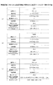
図7は、設定テーブルの一例を示す図である。図7(a)〜(c)に示すように、設定テーブルにはそれぞれ、設定テーブルの名称("設定1"、"設定2"、"設定3")が付されている。 FIG. 7 is a diagram illustrating an example of the setting table. As shown in FIGS. 7A to 7C, the setting tables are given the names of the setting tables (“setting 1”, “setting 2”, “setting 3”), respectively.
無線通信するにあたり、表示装置110及び情報端末120に設定されるべき項目には、通信モード、認証方式、暗号方式、周波数チャンネル、伝送規格、通信プロトコル、接続される無線装置のIPv4アドレス、IPv4サブネットマスクアドレス等が含まれる。
Items to be set in the
通信モードには、アドホックモードまたはソフトAP(Access Point)モードが設定される。なお、ソフトAPモードとは、表示装置をソフトウェアレベルでアクセスポイントとして機能させるモードである。 As the communication mode, an ad hoc mode or a soft AP (Access Point) mode is set. The soft AP mode is a mode in which the display device functions as an access point at the software level.
認証方式及び暗号方式については、様々な公知の技術を採用することができる。例えば、暗号方式としては、WEP(Wired Equivalent Privacy)やWPS(Wi-Fi Protected Setup)が一例として挙げられる。 Various known techniques can be employed for the authentication method and the encryption method. For example, examples of encryption methods include WEP (Wired Equivalent Privacy) and WPS (Wi-Fi Protected Setup).
通信プロトコルは、IPv(Internet Protocol Version)4であってもIPv6であっても、その他の独自のプロトコルであってもよい。IPv4アドレスとIPv4サブネットマスクアドレスは対になって使用され、互いに対応した値をとる。IPv6とIPv6プレフィックスも同様に互いに対応した値をとる。 The communication protocol may be IPv (Internet Protocol Version) 4, IPv6, or other unique protocol. The IPv4 address and the IPv4 subnet mask address are used as a pair and take values corresponding to each other. Similarly, the IPv6 and IPv6 prefixes have values corresponding to each other.
設定テーブルには、これらの項目のほか、周波数チャンネルや伝送規格が含まれる。伝送規格では、IEEE802の種別を特定する。
In addition to these items, the setting table includes frequency channels and transmission standards. In the transmission standard, the type of
なお、本実施形態においては、表示装置A(110)または表示装置A'(110')と無線接続する場合には、図7(a)の設定テーブル(設定1)が用いられるものとする。また、表示装置B(510)、表示装置C(511)と無線接続する場合には、図7(b)、(c)の設定テーブル(設定2または設定3)が用いられるものとする(図5の関連テーブル500参照)。 In the present embodiment, when wirelessly connected to the display device A (110) or the display device A ′ (110 ′), the setting table (setting 1) in FIG. 7A is used. When wirelessly connected to the display device B (510) and the display device C (511), the setting table (setting 2 or setting 3) in FIGS. 7B and 7C is used (FIG. 7). 5).
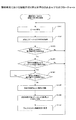
<再生システムにおける接続処理の流れ>
次に、再生システム100における接続処理の流れについて説明する。図8、図9は、再生システム100における接続処理の流れを示すシーケンス図である。
<Flow of connection processing in playback system>
Next, the flow of connection processing in the
はじめに、ユーザは情報端末120の電源をオンし、再生制御プログラム122を起動させることで、接続プログラム(接続側)121を起動する(ステップS801)。続いて、各表示装置の電源をオンすることで、再生プログラム112を起動する(ステップS802)。
First, the user turns on the
各表示装置では、電源がオンされることで、接続プログラム(被接続側)111が起動すると、予め決められた設定情報を設定するとともに(ステップS803)、自装置の製品識別子、個体識別子を含むSSIDを生成する(ステップS804)。 In each display device, when the connection program (connected side) 111 is activated by turning on the power, predetermined setting information is set (step S803), and the product identifier and individual identifier of the own device are included. An SSID is generated (step S804).
具体的には、表示装置A(110)の場合、図7(a)の設定テーブル(設定1)に基づく設定情報を設定するとともに、図6(a)のSSIDを生成する。また、表示装置A'(110')の場合、図7(a)の設定テーブル(設定1)に基づく設定情報を設定するとともに、図6(b)のSSIDを生成する。なお、ここでいう設定情報の設定には、新たに設定情報を設定する場合のほか、既に設定されている設定情報を変更する場合も含むものとする。 Specifically, in the case of the display device A (110), setting information based on the setting table (setting 1) in FIG. 7A is set and the SSID in FIG. 6A is generated. In the case of the display device A ′ (110 ′), setting information based on the setting table (setting 1) in FIG. 7A is set and the SSID in FIG. 6B is generated. Note that the setting information setting here includes not only setting new setting information but also changing setting information that has already been set.
更に、表示装置B(510)の場合、図7(b)の設定テーブル(設定2)に基づく設定情報を設定するとともに、図6(c)のSSIDを生成する。表示装置C(511)の場合、図7(c)の設定テーブル(設定3)に基づく設定情報を設定するとともに、図6(d)のSSIDを生成する。 Further, in the case of the display device B (510), setting information based on the setting table (setting 2) in FIG. 7B is set and the SSID in FIG. 6C is generated. In the case of the display device C (511), setting information based on the setting table (setting 3) in FIG. 7C is set and the SSID in FIG. 6D is generated.
続いて、各表示装置は、ステップS804においてそれぞれ生成したSSIDを含むビーコンを送信する(ステップS805)。情報端末120では、各表示装置より送信されたビーコンを受信し記憶する(ステップS806)。
Subsequently, each display device transmits a beacon including the SSID generated in step S804 (step S805). The
続いて、ユーザは他の装置512の電源をオンする(ステップS807)。他の装置512においても、電源がオンすると、予め決められた設定情報を設定するとともに(ステップS808)、SSIDを生成する(ステップS809)。なお、他の装置512には、接続プログラム(被接続側)111がインストールされていないため、自装置の製品識別子、個体識別子を含むSSIDは生成されない(図6(e))。なお、他の装置512において、設定される設定情報は、図7(a)から(c)に例示した設定テーブルのいずれかであってもよいし、それ以外の設定テーブルであってもよい。
Subsequently, the user turns on the power of the other device 512 (step S807). In the
続いて、他の装置512では、ステップS809において生成したSSIDを含むビーコンを送信する(ステップS810)。情報端末120では、他の装置512より送信されたビーコンを受信し記憶する(ステップS811)。
Subsequently, the
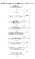
続いて図9に進む。情報端末120では、ステップS806及びステップS811において記憶した全ビーコンからSSIDを取得する(ステップS901)。具体的には、表示装置A(110)のビーコンからは、SSIDとして、図6(a)に示すSSIDを取得する。また、表示装置A'(110')のビーコンからは、図6(b)に示すSSIDを、表示装置B(510)のビーコンからは、図6(c)に示すSSIDを、表示装置C(511)のビーコンからは、図6(d)に示すSSIDをそれぞれ取得する。更に、他の装置512からは、図6(e)に示すSSIDを取得する。
Then, it progresses to FIG. The
続いて、取得した全てのSSIDのうち、製品識別子が含まれているSSIDを選別する(ステップS902)。上述したように、接続プログラム(被接続側)111等により生成されたSSIDの場合、0〜3バイトに製品識別子を示す文字列が記載されている。このため、関連テーブル500を参照しながら、0〜3バイトに、情報端末120が認識している(関連テーブル500に登録されている)製品識別子に対応する製品識別子が記載されているか否かを判定し、記載されていると判定したSSIDを選別する。ここでは、図6(a)〜(d)に示すSSIDが選別される。 Subsequently, the SSID including the product identifier is selected from all the acquired SSIDs (step S902). As described above, in the case of an SSID generated by the connection program (connected side) 111 or the like, a character string indicating a product identifier is described in 0 to 3 bytes. Therefore, referring to the related table 500, whether or not the product identifier corresponding to the product identifier recognized by the information terminal 120 (registered in the related table 500) is described in 0 to 3 bytes. Determine and select SSID determined to be described. Here, the SSIDs shown in FIGS. 6A to 6D are selected.
続いて、製品識別子が含まれているSSIDのうち、ビーコンの受信強度が最大のSSIDを判定する(ステップS903)。図10は、受信した各ビーコンに含まれるSSIDにより特定されるネットワークと、SSIDに含まれる製品識別子に対応付けられた設定テーブルと、各ビーコンの受信強度との関係をまとめた図である。ここでは、図6(a)から(d)に示すSSIDを、それぞれ、SSID(A)、SSID(A')、SSID(B)、SSID(C)としている。 Subsequently, among the SSIDs including the product identifier, the SSID having the maximum beacon reception strength is determined (step S903). FIG. 10 is a diagram summarizing the relationship between the network specified by the SSID included in each received beacon, the setting table associated with the product identifier included in the SSID, and the reception intensity of each beacon. Here, the SSIDs shown in FIGS. 6A to 6D are respectively SSID (A), SSID (A ′), SSID (B), and SSID (C).
各SSIDには、個体識別子が含まれているため、複数の表示装置間で、SSIDが重複することはない。このため、図10に示すように、同じ設定テーブルが設定され、IPアドレスが同じになったとしても、SSIDが異なるため、各表示装置間でIPアドレスの衝突が起きることはない。 Since each SSID includes an individual identifier, the SSID does not overlap among a plurality of display devices. For this reason, as shown in FIG. 10, even if the same setting table is set and the IP addresses are the same, the SSIDs are different, so that there is no IP address collision between the display devices.
なお、図10の例は、表示装置A(110)により送信されたビーコンの受信強度が最大であり、SSID(A)が選別された場合を示している。 Note that the example of FIG. 10 shows a case where the reception intensity of the beacon transmitted by the display device A (110) is the maximum and the SSID (A) is selected.
続いて、ステップS903において選別したSSID(ここでは、SSID(A))のネットワークを、情報端末120が無線接続すべきネットワークであると判断する。そこで、当該選別したSSID(ここでは、SSID(A))のネットワークを、接続先ネットワークとして特定する(ステップS904)。
Subsequently, it is determined that the network of the SSID selected in step S903 (here, SSID (A)) is a network to which the
続いて、関連テーブル500を参照することにより、ステップS903において選別したSSIDに含まれる製品識別子に対応付けられた設定テーブルを特定する(ここでは、"設定1"を特定する)。そして、当該設定テーブルを読み出し、情報端末120による無線通信において用いられる設定情報を設定する(ステップS905)。
Subsequently, by referring to the association table 500, the setting table associated with the product identifier included in the SSID selected in step S903 is specified (here, “setting 1” is specified). And the said setting table is read and the setting information used in the wireless communication by the
続いて、情報端末120では、無線接続の設定が完了したことを、接続先(ここでは、表示装置A)に送信する(ステップS906)。更に、情報端末120の出力部326に、接続先に関する情報を表示する(ステップS907)。具体的には、SSIDの13バイトから27バイトに含まれる、接続先に関する情報を抽出し、出力部326に表示する。
Subsequently, the
図11は、情報端末120の出力部326に表示された表示画面1100の一例を示す図である。図11に示すように、表示画面1100には、無線接続した接続先に関する情報1101として、装置名称とSSIDとが表示される。
FIG. 11 is a diagram illustrating an example of a
接続先に関する情報が明示され、無線接続が完了したことを認識すると、ユーザは、情報端末120を介して、表示装置110において再生する再生コンテンツデータの生成に必要な指示を入力したり、再生制御情報の生成に必要な指示を入力したりする。また、再生コンテンツデータの生成及び再生制御情報の生成が終了すると、再生コンテンツデータ及び再生制御情報を表示装置110に送信するよう指示する(ステップS908)。
When the information about the connection destination is specified and it is recognized that the wireless connection has been completed, the user inputs an instruction necessary for generating playback content data to be played back on the
情報端末120では、再生制御プログラム122が実行されることにより、再生コンテンツデータ及び再生制御情報を生成するとともに、生成した再生コンテンツデータ及び再生制御情報を表示装置A(110)に送信する(ステップS909)。これにより、表示装置A(110)では、再生制御情報に基づいて、再生コンテンツデータの再生を行うことができる。
The
<まとめ>
以上の説明から明らかなように、本実施形態では、
・被接続側の通信装置である表示装置と、接続側の通信装置である情報端末とに、それぞれ、無線通信に用いられる設定情報が格納された設定テーブルを保持させる構成とした。
・被接続側の通信装置である表示装置では、いずれの設定テーブルを用いるかを特定すべく、所定の位置に製品識別子を記載したSSIDを含むビーコンを送信する構成とした。
・被接続側の通信装置である表示装置では、自装置が構築するネットワークを固有化すべく、SSIDに個体識別子を含める構成とした。
・接続側の通信装置である情報端末では、受信したビーコンに含まれるSSIDの所定の位置に、製品識別子が記載されているか否かを判定することで、無線接続可能な通信装置か否かを判定する構成とした。
・無線接続可能な通信装置が複数あった場合、ビーコン受信時の受信強度が最大のビーコンに含まれるSSIDのネットワークを、情報端末が接続するネットワークとして特定する構成とした。
・受信強度が最大のビーコンに含まれるSSIDに記載された製品識別子に対応付けられた設定テーブルの設定情報を、接続側の通信装置である情報端末に設定する構成とした。
<Summary>
As is clear from the above description, in this embodiment,
The display device, which is the communication device on the connected side, and the information terminal, which is the communication device on the connection side, each have a configuration in which a setting table storing setting information used for wireless communication is held.
The display device, which is a communication device on the connected side, is configured to transmit a beacon including an SSID in which a product identifier is described at a predetermined position in order to specify which setting table is used.
The display device, which is a communication device on the connected side, is configured to include an individual identifier in the SSID in order to make the network constructed by the device unique.
In the information terminal that is the communication device on the connection side, it is determined whether or not the communication device is wirelessly connectable by determining whether or not the product identifier is described at a predetermined position of the SSID included in the received beacon. It was set as the structure judged.
-When there are a plurality of wirelessly connectable communication devices, the SSID network included in the beacon having the maximum reception strength when receiving a beacon is specified as the network to which the information terminal is connected.
The configuration information in the setting table associated with the product identifier described in the SSID included in the beacon with the highest reception strength is set in the information terminal that is the communication device on the connection side.
このように、接続側の通信装置が、ビーコンに含まれる製品識別子に基づいて、無線通信に必要な設定を行うため、接続操作が容易になる。また、接続先となるネットワークをスキャンする必要がないため、スキャン時間を短縮することができる。 As described above, since the communication device on the connection side performs settings necessary for wireless communication based on the product identifier included in the beacon, the connection operation is facilitated. In addition, since it is not necessary to scan the connection destination network, the scan time can be shortened.
更に、被接続側の通信装置と接続側の通信装置の両方が、対応する設定テーブルを備えており、ビーコンに含まれるSSIDに製品識別子を記載することでいずれの設定テーブルを用いるかを特定するため、設定後に、設定内容を相互に送信する必要がない。このため、データの送受信(例えば、再生コンテンツデータや再生制御情報の送受信)を開始するまでの時間を短縮させることができる。 Furthermore, both the communication device on the connected side and the communication device on the connection side have a corresponding setting table, and specify which setting table to use by describing the product identifier in the SSID included in the beacon. Therefore, it is not necessary to transmit the setting contents to each other after the setting. For this reason, it is possible to shorten the time until transmission / reception of data (for example, transmission / reception of reproduction content data and reproduction control information) is started.
この結果、本実施形態によれば、通信装置間の無線接続を迅速に行うことができるようになる。 As a result, according to the present embodiment, wireless connection between communication devices can be performed quickly.
なお、本実施形態によれば、上記効果に加え、更に以下のような効果が奏される。 According to this embodiment, in addition to the above effects, the following effects are further exhibited.
例えば、製品識別子により設定テーブルが決定されるため、IPアドレスのバージョンに関わらず、SSIDの記載を、SSIDのバイト長に収めることができる。このため、IPアドレスのバージョンによっては、被接続側の通信装置が、無線通信に必要な設定を行うためのビーコンを送信できなくなる、といった事態を回避することができる。 For example, since the setting table is determined by the product identifier, the description of the SSID can be stored in the byte length of the SSID regardless of the version of the IP address. For this reason, depending on the version of the IP address, it is possible to avoid a situation in which the communication device on the connected side cannot transmit a beacon for performing settings necessary for wireless communication.
また、SSIDに個体識別子を記載することで、被接続側の通信装置である表示装置が構築するネットワークが固有化されるため、異なる表示装置間で同じ設定テーブルを用いたとしても、IPアドレスの衝突が生じることはない。この結果、予め保持すべき設定テーブルの数を抑えることができる。 In addition, by describing the individual identifier in the SSID, the network constructed by the display device that is the communication device on the connected side is unique, so even if the same setting table is used between different display devices, the IP address There is no collision. As a result, the number of setting tables that should be held in advance can be reduced.
更に、無線接続可能な通信装置が複数あった場合でも、受信強度に基づいて、1つの接続先が決定されるため、ユーザは、電源をオンし、接続プログラムを起動するだけで、無線接続を実現することができる。つまり、接続操作が極めて容易となる。 Furthermore, even if there are multiple communication devices that can be connected wirelessly, one connection destination is determined based on the reception strength, so the user can turn on the power and start the connection program to establish a wireless connection. Can be realized. That is, the connection operation is extremely easy.
[第2の実施形態]
上記第1の実施形態では、被接続側の通信装置である表示装置と、接続側の通信装置である情報端末とが無線接続するまでの接続処理について説明したが、本発明はこれに限定されない。例えば、無線接続が完了し、通信処理(再生コンテンツデータや再生制御情報を送受信する処理)を実行している最中においても、ビーコンを監視し、接続先を自動的に切り替える構成としてもよい。
[Second Embodiment]
In the first embodiment, the connection process until the display device, which is the communication device on the connected side, and the information terminal, which is the communication device on the connection side, are wirelessly connected has been described. However, the present invention is not limited to this. . For example, a configuration may be adopted in which a beacon is monitored and a connection destination is automatically switched even when wireless connection is completed and communication processing (processing for transmitting and receiving playback content data and playback control information) is being performed.
<接続先の切り替え処理>
無線接続処理完了後の接続先の切り替え処理について、図12を用いて説明する。図12は、情報端末120における、無線接続処理完了後の接続先の切り替え処理の流れを示すフローチャートである。無線接続処理が完了すると、図12に示す処理が開始される。
<Connection switching process>
The connection destination switching process after the completion of the wireless connection process will be described with reference to FIG. FIG. 12 is a flowchart illustrating the flow of the connection destination switching process after the wireless connection process is completed in the
ステップS1201では、ビーコンの受信を継続する。ステップS1202では、SSID解析部425が、受信したビーコンに含まれるSSIDを取得する。
In step S1201, reception of a beacon is continued. In step S1202, the
ステップS1203では、識別子判定部426がステップS1202において取得したSSIDの0〜3バイトに、製品識別子が記載されているか否かを判定する。具体的には、取得したSSIDの0〜3バイトに、情報端末120が認識している製品識別子に対応する製品識別子が記載されているか否かを、関連テーブル500を参照しながら判定する。
In step S1203, the
ステップS1203において、製品識別子が記載されていないと判定された場合には、当該ビーコンを送信する装置は、情報端末120による無線接続が可能な装置ではないと判断し、ステップS1201に戻る。
If it is determined in step S1203 that the product identifier is not described, the device that transmits the beacon determines that the device is not capable of wireless connection by the
一方、ステップS1203において、製品識別子が記載されていると判定された場合には、ステップS1204に進む。ステップS1204では、受信強度判定部427が、ステップS1203において製品識別子が記載されていると判定されたSSIDを含むビーコンの受信強度を取得する。そして、現時点で無線接続している接続先(例えば、表示装置A(110))から送信されているビーコンの受信強度との比較を行う。
On the other hand, if it is determined in step S1203 that the product identifier is described, the process proceeds to step S1204. In step S1204, the reception
ステップS1204における比較の結果、現時点で無線接続している接続先から送信されるビーコンの受信強度のほうが高いと判定した場合には、ステップS1201に戻る。 As a result of the comparison in step S1204, if it is determined that the reception intensity of the beacon transmitted from the connection destination that is currently wirelessly connected is higher, the process returns to step S1201.
一方、比較の結果、現時点で無線接続している接続先から送信されるビーコンの受信強度より、ステップS1203において製品識別子が記載されていると判定されたSSIDを含むビーコンの受信強度の方が高いと判定した場合には、ステップS1205に進む。 On the other hand, as a result of comparison, the reception intensity of the beacon including the SSID determined to have the product identifier described in step S1203 is higher than the reception intensity of the beacon transmitted from the connection destination that is currently wirelessly connected. If it is determined, the process proceeds to step S1205.
ステップS1205では、接続制御部423が、現時点で無線接続している接続先との無線接続を切断する。更に、ステップS1206では、ステップS1203において製品識別子が記載されていると判定されたSSIDのネットワーク(例えば、表示装置B(510)のSSID(B)のネットワーク)に接続する。
In step S1205, the
ステップS1207では、ステップS1203において製品識別子が記載されていると判定されたSSIDの製品識別子に対応付けられた設定テーブル(設定2)を読み出し、当該設定テーブルに基づいて設定情報を設定する。 In step S1207, a setting table (setting 2) associated with the product identifier of the SSID determined to have the product identifier described in step S1203 is read, and setting information is set based on the setting table.
これにより、例えば、ユーザは、情報端末120を持って移動するだけで、無線接続の接続先を自動的に切り替えることが可能となる。
Thereby, for example, the user can automatically switch the connection destination of the wireless connection only by moving with the
<まとめ>
以上の説明から明らかなように、本実施形態では、
・無線接続処理が完了した後も、ビーコンを監視する構成とした。
・受信したビーコンのうち、SSIDに製品識別子が記載されているビーコンについては、ビーコンの受信強度を判定し、現時点で無線接続している接続先から送信されるビーコンの受信強度と比較する構成とした。
・比較の結果、現時点で無線接続している接続先から送信されるビーコンの受信強度よりも受信強度が高いビーコンがあった場合には、当該ビーコンに含まれるSSIDのネットワークに接続を切り替える構成とした。
<Summary>
As is clear from the above description, in this embodiment,
-Beacon is monitored even after wireless connection processing is completed.
Of the received beacons, for the beacons whose product identifier is described in the SSID, the reception strength of the beacons is determined and compared with the reception strength of the beacons transmitted from the connection destination that is currently wirelessly connected did.
As a result of comparison, when there is a beacon whose reception intensity is higher than the reception intensity of the beacon transmitted from the currently connected destination, the connection is switched to the network of the SSID included in the beacon. did.
これにより、無線接続処理が完了した後においても、無線接続を迅速に切り替えることが可能となる。 Thereby, even after the wireless connection process is completed, it is possible to quickly switch the wireless connection.
[第3の実施形態]
上記第2の実施形態では、ビーコンの受信強度の比較の結果、現時点で無線接続している接続先から送信されるビーコンの受信強度よりも高いビーコンがあった場合には、直ちに、当該ビーコンに含まれるSSIDのネットワークに接続を切り替える構成とした。
[Third Embodiment]
In the second embodiment, if there is a beacon that is higher than the reception strength of the beacon transmitted from the connection destination that is currently wirelessly connected as a result of the comparison of the reception strength of the beacon, The connection is switched to the included SSID network.
しかしながら、本発明はこれに限定されない。例えば、切り替える際に、被接続側の通信装置である表示装置と、接続側の通信装置である情報端末との間で、データ(例えば、再生コンテンツデータや再生制御情報)の送受信を行っていた場合には、送受信が完了してから、切り替えを行うよう構成してもよい。 However, the present invention is not limited to this. For example, when switching, data (for example, playback content data and playback control information) is transmitted and received between a display device that is a communication device on the connected side and an information terminal that is a communication device on the connection side In some cases, switching may be performed after transmission / reception is completed.
図13は、情報端末120における、無線接続処理完了後の接続先の切り替え処理の流れを示すフローチャートである。なお、上記第2の実施形態において説明した図12のフローチャートと同じ処理については、同じ参照番号を付すこととし、ここでは説明を省略する。
FIG. 13 is a flowchart illustrating the flow of the connection destination switching process after the wireless connection process is completed in the
図12との相違点は、ステップS1204において、製品識別子が記載されていると判定されたSSIDを含むビーコンの受信強度の方が高いと判定した場合の処理である。 The difference from FIG. 12 is the processing when it is determined in step S1204 that the reception intensity of the beacon including the SSID determined to have the product identifier is higher.
この場合、本実施形態では、ステップS1301において、接続制御部423が、現時点で無線接続している接続先との間で、データの送受信を行っているか否かを判定する。ステップS1301において、データの送受信を行っていると判定された場合には、データの送受信が完了するまで待機する。
In this case, in this embodiment, in step S1301, the
一方、ステップS1301において、データの送受信を行っていないと判定された場合には、ステップS1205に進む。 On the other hand, if it is determined in step S1301 that data is not being transmitted / received, the process advances to step S1205.
これにより、データの送受信を中断させることなく、接続先の切り替えを行うことが可能となる。 This makes it possible to switch the connection destination without interrupting data transmission / reception.
[第4の実施形態]
上記第2及び第3の実施形態では、ビーコンの受信強度に応じて、無線接続の接続先を自動的に切り替える構成としたが、本発明はこれに限定されない。例えば、切り替え前にユーザに問い合わせメッセージを表示し、ユーザより、当該問い合わせメッセージに対する回答として、切り替え指示が入力された場合に、無線接続の接続先を切り替える構成としてもよい。
[Fourth Embodiment]
In the said 2nd and 3rd embodiment, it was set as the structure which switches the connecting point of a wireless connection automatically according to the reception intensity | strength of a beacon, However, This invention is not limited to this. For example, an inquiry message may be displayed to the user before switching, and the connection destination of the wireless connection may be switched when a switching instruction is input as a response to the inquiry message from the user.
図14は、情報端末120における、無線接続処理完了後の接続先の切り替え処理の流れを示すフローチャートである。なお、上記第2の実施形態において説明した図12のフローチャートと同じ処理については、同じ参照番号を付すこととし、ここでは説明を省略する。
FIG. 14 is a flowchart illustrating the flow of the connection destination switching process after the wireless connection process is completed in the
図12との相違点は、ステップS1204において、製品識別子が記載されていると判定されたSSIDを含むビーコンの受信強度の方が高いと判定した場合の処理である。 The difference from FIG. 12 is the processing when it is determined in step S1204 that the reception intensity of the beacon including the SSID determined to have the product identifier is higher.
この場合、本実施形態では、ステップS1401において、表示制御部424が現時点で無線接続している接続先を、受信強度の高いビーコンに含まれるSSIDのネットワークに切り替えるか否かを、ユーザに問い合わせる。
In this case, in this embodiment, in step S1401, the
ステップS1402では、ステップS1401における問い合わせに対する回答として、切り替えを行わない旨の指示をユーザ操作部421が受け付けた場合には、ステップS1201に戻る。一方、ステップS1401における問い合わせに対する回答として、切り替えを行う旨の指示をユーザ操作部421が受け付けた場合には、ステップS1205に進む。
In step S1402, when the
このように、ユーザの指示に基づいて、切り替えを行う構成とすることで、ユーザの意図に反して、無線接続の接続先が切り替わってしまうといった事態を回避することが可能となる。 Thus, by adopting a configuration in which switching is performed based on a user's instruction, it is possible to avoid a situation in which the connection destination of a wireless connection is switched against the user's intention.
[第5の実施形態]
上記第2及び第3の実施形態では、ビーコンの受信強度に応じて、無線接続の接続先を自動的に切り替える構成としたが、本発明はこれに限定されない。例えば、自動的に切り替えるタイミングをユーザが指定する構成としてもよい。
[Fifth Embodiment]
In the said 2nd and 3rd embodiment, it was set as the structure which switches the connecting point of a wireless connection automatically according to the reception intensity | strength of a beacon, However, This invention is not limited to this. For example, it is good also as a structure which a user designates the timing switched automatically.
図15は、情報端末120における、無線接続処理完了後の接続先の切り替え処理の流れを示すフローチャートである。なお、上記第2の実施形態において説明した図12のフローチャートと同じ処理については、同じ参照番号を付すこととし、ここでは説明を省略する。
FIG. 15 is a flowchart illustrating the flow of the connection destination switching process after the wireless connection process is completed in the
図15との相違点は、ステップS1204において、製品識別子が記載されていると判定されたSSIDを含むビーコンの受信強度の方が高いと判定した場合の処理である。 The difference from FIG. 15 is processing when it is determined in step S1204 that the reception intensity of the beacon including the SSID for which the product identifier is determined is higher.
この場合、本実施形態では、ステップS1501において、ユーザ操作部421が、ユーザにより再接続ボタン(不図示)が押圧されたか否かを判定する。ステップS1501において再接続ボタンが押圧されていないと判定された場合には、ステップS1201に戻る。つまり、切り替え先がある場合であっても、ユーザからの指示がない限り、当該切り替え先に切り替えられることはない。
In this case, in this embodiment, in step S1501, the
一方、ステップS1501において、ユーザ操作部421が、再接続ボタンが押圧されたと判定した場合には、ステップS1205に進む。つまり、ユーザからの指示が入力されたタイミングで、接続先が切り替えられることとなる。
On the other hand, if the
なお、切り替え先がない場合には、ユーザからの指示が入力された場合であっても、接続先が切り替わることはない。 When there is no switching destination, the connection destination is not switched even when an instruction from the user is input.
[その他の実施形態]
上記第1の実施形態では、ビーコンの受信強度が最大のSSIDを判定する構成としたが、本発明はこれに限定されない。例えば、ビーコンの受信強度が、所定の受信強度以上であるSSIDを判定する構成としてもよい。あるいは所定の範囲の受信強度であるSSIDを判定する構成としてもよい。つまり、ビーコンの受信強度が所定の条件を満たすSSIDを判定する構成としてもよい。
[Other Embodiments]
In the first embodiment, the SSID having the maximum beacon reception intensity is determined. However, the present invention is not limited to this. For example, it is good also as a structure which determines the SSID whose receiving intensity of a beacon is more than predetermined receiving intensity. Or it is good also as a structure which determines SSID which is the receiving intensity of a predetermined range. That is, it is good also as a structure which determines SSID with which the receiving intensity of a beacon satisfy | fills a predetermined condition.
上記各実施形態では、SSIDを生成するにあたり、0〜3バイトに製品識別子を記載し、4〜12バイトに個体識別子を記載する構成としたが、本発明はこれに限定されない。製品識別子及び個体識別子を記載する位置は、接続プログラム(被接続側)111と接続プログラム(接続側)121との間で予め定められてさえいれば、任意の位置であってもよい。 In each of the above embodiments, when generating an SSID, a product identifier is described in 0 to 3 bytes and an individual identifier is described in 4 to 12 bytes. However, the present invention is not limited to this. The position where the product identifier and the individual identifier are described may be any position as long as it is predetermined between the connection program (connected side) 111 and the connection program (connection side) 121.
上記各実施形態では、本発明に係る通信システムの一例として再生システムを挙げたが、本発明はこれに限定されない。電子装置同士をネットワークにより無線接続し、データの送受信を行うシステムであれば、どのようなシステムであってもよい。 In each of the above embodiments, the playback system has been described as an example of the communication system according to the present invention, but the present invention is not limited to this. Any system may be used as long as the electronic devices are wirelessly connected to each other via a network and transmit and receive data.
例えば、上記各実施形態では、通信システム100を構成する電子装置として、プロジェクタ211やディスプレイ等の機器を例示したが、本発明はこれに限定されない。図16は、様々な電子装置を用いて通信システム100を構成した場合の、システム構成の一例を示す図である。
For example, in each of the embodiments described above, devices such as the
図16(a)、(b)に示すように、例えば、テレビ会議システム1601や電子ホワイトボード1602等の電子装置を用いて通信システム100を構成してもよい。あるいは、図16(c)に示すように、MFP(Multi-Function Peripheral)1603やプリンタ(不図示)等の印刷機能を有する電子装置を用いて通信システム100を構成してもよい。なお、MFP1603やプリンタ等の印刷機能を有する電子装置の場合、情報端末120では、再生コンテンツデータを送信する代わりに、印刷データを送信するようにしてもよい。
As shown in FIGS. 16A and 16B, for example, the
以上、各実施形態に基づき本発明の説明を行ってきたが、上記実施形態に示した要件に本発明が限定されるものではない。これらの点に関しては、本発明の主旨をそこなわない範囲で変更することができ、その応用形態に応じて適切に定めることができる。 As mentioned above, although this invention has been demonstrated based on each embodiment, this invention is not limited to the requirements shown in the said embodiment. With respect to these points, the gist of the present invention can be changed without departing from the scope of the present invention, and can be appropriately determined according to the application form.
100 再生システム
110 表示装置
111 接続プログラム(被接続側)
112 再生プログラム
120 情報端末
121 接続プログラム(接続側)
122 再生制御プログラム
211 プロジェクタ
212 スクリーン
411 ユーザ操作部
412 無線設定保持部
413 接続制御部
414 SSID生成部
415 識別子生成部
421 ユーザ操作部
422 無線設定保持部
423 接続制御部
424 表示制御部
425 SSID解析部
426 識別子判定部
427 受信強度判定部
100
112
122
Claims (11)
前記第1の通信装置は、
前記第1の通信装置と前記第2の通信装置との間の無線通信に用いられる設定情報が格納された設定テーブルを特定する特定情報と前記第1の通信装置に個別に付けられた個体識別子とを含むネットワーク識別子を生成する生成手段と、
前記生成手段により生成されたネットワーク識別子を含むビーコン信号を送信する送信手段と、を有し、
前記第2の通信装置は、
受信したビーコン信号から取得したネットワーク識別子のうち、前記特定情報が含まれ、かつ、受信したビーコン信号の受信強度が所定の条件を満たすネットワーク識別子を識別する識別手段と、
前記識別したネットワーク識別子に含まれる前記特定情報により特定される設定テーブルを用いて、前記識別したネットワーク識別子に基づいて特定されるネットワークを形成する前記第1の通信装置との間の無線通信に用いられる設定情報を前記第2の通信装置に設定する設定手段と
を有することを特徴とする通信システム。 A communication system having a first communication device and a second communication device,
The first communication device is:
Specific information for specifying a setting table in which setting information used for wireless communication between the first communication device and the second communication device is stored, and an individual identifier individually assigned to the first communication device a generating means for generating a network identifier that includes bets,
Transmitting means for transmitting a beacon signal including the network identifier generated by the generating means,
The second communication device is:
Of the network identifier acquired from the received beacon signal, the specific information includes, and the reception intensity of the received beacon signal identifying means for identifying a predetermined condition is satisfied network identifier,
Using a setting table which is specified by the specifying information included in the identified network identifier, used for wireless communication with the identified first communication device forming a network which is specified on the basis of the network identifier And setting means for setting the setting information to be set in the second communication device.
前記第1の通信装置は、
前記第1の通信装置と前記第2の通信装置との間の無線通信に用いられる設定情報が格納された設定テーブルを特定する特定情報と前記第1の通信装置に個別に付けられた個体識別子とを含むネットワーク識別子を生成する生成手段と、
前記生成手段により生成されたネットワーク識別子を含むビーコン信号を送信する送信手段と、を有し、
前記接続プログラムは、前記第2の通信装置のコンピュータに、
受信したビーコン信号から取得したネットワーク識別子のうち、前記特定情報が含まれ、かつ、受信したビーコン信号の受信強度が所定の条件を満たすネットワーク識別子を識別する識別手順と、
前記識別したネットワーク識別子に含まれる前記特定情報により特定される設定テーブルを用いて、前記識別したネットワーク識別子に基づいて特定されるネットワークを形成する前記第1の通信装置との間の無線通信に用いられる設定情報を前記第2の通信装置に設定する設定手順と
を実行させることを特徴とする通信制御システム。 A communication control system including a first communication device and a connection program executed in a second communication device wirelessly connected to the first communication device,
The first communication device is:
Specific information for specifying a setting table in which setting information used for wireless communication between the first communication device and the second communication device is stored, and an individual identifier individually assigned to the first communication device a generating means for generating a network identifier that includes bets,
Transmitting means for transmitting a beacon signal including the network identifier generated by the generating means,
The connection program is stored in the computer of the second communication device.
Of the network identifier acquired from the received beacon signal, the specific information includes, and the reception intensity of the received beacon signal and the identification procedure for identifying a predetermined condition is satisfied network identifier,
Using a setting table which is specified by the specifying information included in the identified network identifier, used for wireless communication with the identified first communication device forming a network which is specified on the basis of the network identifier And a setting procedure for setting the setting information to be set in the second communication device.
前記設定手順は、
前記第2の通信装置において保持された設定テーブルから、前記特定情報により特定される設定テーブルを読み出して、前記設定情報を前記第2の通信装置に設定することを特徴とする請求項2記載の通信制御システム。 The second communication device holds the setting table,
The setting procedure is as follows:
3. The setting table specified by the specific information is read from a setting table held in the second communication device, and the setting information is set in the second communication device. Communication control system.
前記第2の通信装置において保持された設定テーブルと前記特定情報とを対応付ける関連テーブルを参照し、該関連テーブルにおいて対応付けられている特定情報が、前記受信したビーコン信号に含まれるネットワーク識別子の所定の位置に記載されている場合に、該ネットワーク識別子に前記特定情報が含まれていると判定することを特徴とする請求項3に記載の通信制御システム。 The identification procedure is:
Reference is made to an association table that associates the setting table held in the second communication device with the specific information, and the specific information associated with the association table is a predetermined network identifier included in the received beacon signal. 4. The communication control system according to claim 3, wherein it is determined that the specific information is included in the network identifier.
前記識別したネットワーク識別子に基づいて接続先のネットワークを特定することを特徴とする請求項2または3に記載の通信制御システム。 The setting procedure is as follows:
The communication control system according to claim 2 or 3, wherein identifying a network to connect to the identified based on the network identifier.
前記識別したネットワーク識別子を含むビーコン信号よりも受信強度が高く、ネットワーク識別子に前記特定情報が含まれるビーコン信号を受信したとき、前記接続先のネットワークを、該受信したビーコン信号に含まれるネットワーク識別子に基づいて特定されるネットワークに切り替える切替手順を更に実行させることを特徴とする請求項5に記載の通信制御システム。 The connection program is stored in the computer of the second communication device.
The identified high reception intensity than the beacon signal including the network identifier, upon receiving the beacon signal included the specific information to the network identifier, the network of the destination, the network identifier included in the beacon signal thus received The communication control system according to claim 5, further comprising a switching procedure for switching to a network specified based on the network.
前記第2の通信装置が、前記接続先のネットワークとの通信が終了してから、前記受信したビーコン信号に含まれるネットワーク識別子に基づいて特定されるネットワークに切り替えることを特徴とする請求項6に記載の通信制御システム。 The switching procedure is:
7. The second communication device switches to a network specified based on a network identifier included in the received beacon signal after communication with the connection destination network ends. The communication control system described.
前記識別したネットワーク識別子を含むビーコン信号よりも受信強度が高く、ネットワーク識別子に前記特定情報が含まれるビーコン信号を受信した場合であって、ユーザにより所定の指示が入力された場合に、前記接続先のネットワークを、該受信したビーコン信号に含まれるネットワーク識別子に基づいて特定されるネットワークに切り替えることを特徴とする請求項6に記載の通信制御システム。 The switching procedure is:
The high reception intensity than the beacon signal including the identified network identifier, a case of receiving a beacon signal included the specific information to the network identifier, when a predetermined instruction is input by the user, the connection destination The communication control system according to claim 6, wherein the network is switched to a network specified based on a network identifier included in the received beacon signal.
前記他の通信装置と前記通信装置との間の無線通信に用いられる設定情報が格納された設定テーブルを特定する特定情報と前記通信装置に個別に付けられた個体識別子とを含むネットワーク識別子が含まれたビーコン信号を受信する受信手段と、
受信したビーコン信号から取得したネットワーク識別子のうち、前記特定情報が含まれ、かつ、受信したビーコン信号の受信強度が所定の条件を満たすネットワーク識別子を識別する識別手段と、
前記識別したネットワーク識別子に含まれる前記特定情報により特定される設定テーブルを用いて、前記識別したネットワーク識別子に基づいて特定されるネットワークを形成する前記他の通信装置との間の無線通信に用いられる設定情報を前記通信装置に設定する設定手段と
を有することを特徴とする通信装置。 A communication device wirelessly connected to another communication device,
Includes a network identifier including specific information for specifying a setting table in which setting information used for wireless communication between the other communication device and the communication device is stored, and an individual identifier individually assigned to the communication device Receiving means for receiving the received beacon signal;
Of the network identifier acquired from the received beacon signal, the specific information includes, and the reception intensity of the received beacon signal identifying means for identifying a predetermined condition is satisfied network identifier,
Using a setting table which is specified by the specifying information included in the identified network identifier, used for wireless communication with the other communication device to form a network that is identified based on the identified network identifier And a setting unit configured to set setting information in the communication device.
前記他の通信装置と前記通信装置との間の無線通信に用いられる設定情報が格納された設定テーブルを特定する特定情報と前記通信装置に個別に付けられた個体識別子とを含むネットワーク識別子が含まれたビーコン信号を受信する受信手順と、
受信したビーコン信号から取得したネットワーク識別子のうち、前記特定情報が含まれ、かつ、受信したビーコン信号の受信強度が所定の条件を満たすネットワーク識別子を識別する識別手順と、
前記識別したネットワーク識別子に含まれる前記特定情報により特定される設定テーブルを用いて、前記識別したネットワーク識別子に基づいて特定されるネットワークを形成する前記他の通信装置との間の無線通信に用いられる設定情報を前記通信装置に設定する設定手順と
を実行させることを特徴とする接続プログラム。 To a computer of a communication device wirelessly connected to another communication device,
Includes a network identifier including specific information for specifying a setting table in which setting information used for wireless communication between the other communication device and the communication device is stored, and an individual identifier individually assigned to the communication device Receiving procedure for receiving the received beacon signal;
Of the network identifier acquired from the received beacon signal, the specific information includes, and the reception intensity of the received beacon signal and the identification procedure for identifying a predetermined condition is satisfied network identifier,
Using a setting table which is specified by the specifying information included in the identified network identifier, used for wireless communication with the other communication device to form a network that is identified based on the identified network identifier A connection program for executing a setting procedure for setting setting information in the communication device.
前記第1の通信装置が、
前記第1の通信装置と前記第2の通信装置との間の無線通信に用いられる設定情報が格納された設定テーブルを特定する特定情報と前記第1の通信装置に個別に付けられた個体識別子とを含むネットワーク識別子を生成する生成手順と、
前記生成手順において生成されたネットワーク識別子を含むビーコン信号を送信する送信手順と、を実行し、
前記第2の通信装置が、
受信したビーコン信号から取得したネットワーク識別子のうち、前記特定情報が含まれ、かつ、受信したビーコン信号の受信強度が所定の条件を満たすネットワーク識別子を識別する識別手順と、
前記識別したネットワーク識別子に含まれる前記特定情報により特定される設定テーブルを用いて、前記識別したネットワーク識別子に基づいて特定されるネットワークを形成する前記第1の通信装置との間の無線通信に用いられる設定情報を前記第2の通信装置に設定する設定手順と
を実行することを特徴とする通信方法。 A communication method in a communication system having a first communication device and a second communication device,
The first communication device is
Specific information for specifying a setting table in which setting information used for wireless communication between the first communication device and the second communication device is stored, and an individual identifier individually assigned to the first communication device a generating step of generating a network identifier that includes bets,
Transmitting a beacon signal including the network identifier generated in the generation procedure, and
The second communication device is
Of the network identifier acquired from the received beacon signal, the specific information includes, and the reception intensity of the received beacon signal and the identification procedure for identifying a predetermined condition is satisfied network identifier,
Using a setting table which is specified by the specifying information included in the identified network identifier, used for wireless communication with the identified first communication device forming a network which is specified on the basis of the network identifier A setting procedure for setting setting information to be set in the second communication device.
Priority Applications (9)
| Application Number | Priority Date | Filing Date | Title |
|---|---|---|---|
| JP2014114311A JP5660242B1 (en) | 2013-09-06 | 2014-06-02 | Communication system, communication control system, communication apparatus, communication method, and connection program |
| CA2916670A CA2916670C (en) | 2013-09-06 | 2014-08-06 | A method, device and system for fast wireless connection |
| SG11201510288UA SG11201510288UA (en) | 2013-09-06 | 2014-08-06 | Communication system, communication control system, communication apparatus, communication method, and connection program |
| PCT/JP2014/071354 WO2015033748A1 (en) | 2013-09-06 | 2014-08-06 | Communication system, communication control system, communication apparatus, communication method, and connection program |
| CN201480047786.0A CN105493617B (en) | 2013-09-06 | 2014-08-06 | Communication system, communication control system, communication device, communication means and linker |
| MYPI2016700090A MY182648A (en) | 2013-09-06 | 2014-08-06 | Communication system, communication control system, communication apparatus, communication method, and connection program |
| US14/911,495 US9998968B2 (en) | 2013-09-06 | 2014-08-06 | Communication system, communication control system, communication apparatus, communication method, and connection program |
| EP14842228.0A EP3042538B1 (en) | 2013-09-06 | 2014-08-06 | Communication system, communication control system, communication apparatus, communication method, and connection program |
| RU2016106342A RU2016106342A (en) | 2013-09-06 | 2014-08-06 | COMMUNICATION SYSTEM, COMMUNICATION MANAGEMENT SYSTEM, COMMUNICATION DEVICE, COMMUNICATION METHOD, AND CONNECTION PROGRAM |
Applications Claiming Priority (3)
| Application Number | Priority Date | Filing Date | Title |
|---|---|---|---|
| JP2013185113 | 2013-09-06 | ||
| JP2013185113 | 2013-09-06 | ||
| JP2014114311A JP5660242B1 (en) | 2013-09-06 | 2014-06-02 | Communication system, communication control system, communication apparatus, communication method, and connection program |
Related Child Applications (1)
| Application Number | Title | Priority Date | Filing Date |
|---|---|---|---|
| JP2014244611A Division JP5962743B2 (en) | 2013-09-06 | 2014-12-03 | Communication system, communication control system, communication apparatus, communication method, and connection program |
Publications (2)
| Publication Number | Publication Date |
|---|---|
| JP5660242B1 true JP5660242B1 (en) | 2015-01-28 |
| JP2015073262A JP2015073262A (en) | 2015-04-16 |
Family
ID=52437511
Family Applications (3)
| Application Number | Title | Priority Date | Filing Date |
|---|---|---|---|
| JP2014114311A Expired - Fee Related JP5660242B1 (en) | 2013-09-06 | 2014-06-02 | Communication system, communication control system, communication apparatus, communication method, and connection program |
| JP2014244611A Expired - Fee Related JP5962743B2 (en) | 2013-09-06 | 2014-12-03 | Communication system, communication control system, communication apparatus, communication method, and connection program |
| JP2016131074A Expired - Fee Related JP6388005B2 (en) | 2013-09-06 | 2016-06-30 | Communication system, communication control system, communication apparatus, communication method, and connection program |
Family Applications After (2)
| Application Number | Title | Priority Date | Filing Date |
|---|---|---|---|
| JP2014244611A Expired - Fee Related JP5962743B2 (en) | 2013-09-06 | 2014-12-03 | Communication system, communication control system, communication apparatus, communication method, and connection program |
| JP2016131074A Expired - Fee Related JP6388005B2 (en) | 2013-09-06 | 2016-06-30 | Communication system, communication control system, communication apparatus, communication method, and connection program |
Country Status (9)
| Country | Link |
|---|---|
| US (1) | US9998968B2 (en) |
| EP (1) | EP3042538B1 (en) |
| JP (3) | JP5660242B1 (en) |
| CN (1) | CN105493617B (en) |
| CA (1) | CA2916670C (en) |
| MY (1) | MY182648A (en) |
| RU (1) | RU2016106342A (en) |
| SG (1) | SG11201510288UA (en) |
| WO (1) | WO2015033748A1 (en) |
Families Citing this family (4)
| Publication number | Priority date | Publication date | Assignee | Title |
|---|---|---|---|---|
| CN109845299B (en) * | 2016-11-25 | 2022-09-23 | 索尼公司 | Information processing apparatus, information processing method, program, and information processing system |
| JP7118764B2 (en) * | 2018-06-20 | 2022-08-16 | キヤノン株式会社 | Communication device, control method and program |
| JP7154833B2 (en) | 2018-06-20 | 2022-10-18 | キヤノン株式会社 | Communication device, communication method and program |
| CN111556553B (en) * | 2020-05-11 | 2022-04-12 | 天翼电信终端有限公司 | Wireless screen projection method, terminal, electronic equipment and storage medium |
Citations (10)
| Publication number | Priority date | Publication date | Assignee | Title |
|---|---|---|---|---|
| JP2005167696A (en) * | 2003-12-03 | 2005-06-23 | Canon Inc | Wireless communication controller and its control method |
| JP2006086959A (en) * | 2004-09-17 | 2006-03-30 | Fujitsu Ltd | Radio terminal and ad hoc communication method |
| JP2006157815A (en) * | 2004-12-01 | 2006-06-15 | Kddi Corp | Cellular phone adaptable to wireless lan and wireless lan setting method thereof |
| JP2007135146A (en) * | 2005-11-14 | 2007-05-31 | Fujitsu Access Ltd | System and method for wireless lan communication |
| JP2007143117A (en) * | 2005-10-17 | 2007-06-07 | Canon Inc | Communication apparatus and communication parameter setting method |
| JP2009231971A (en) * | 2008-03-19 | 2009-10-08 | Seiko Epson Corp | Radio communication system, electronic equipment, ad-hoc network establishment method |
| JP2011166600A (en) * | 2010-02-12 | 2011-08-25 | Toshiba Corp | Portable radio terminal |
| JP2013009069A (en) * | 2011-06-23 | 2013-01-10 | Ntt Docomo Inc | Mobile communication system, mobile telephone terminal, data access point and method therefor, using usim proper information |
| JP2013066175A (en) * | 2011-09-02 | 2013-04-11 | Panasonic Corp | Wireless communication device, projector apparatus, wireless communication system, and wireless communication method |
| JP2013179454A (en) * | 2012-02-28 | 2013-09-09 | Brother Ind Ltd | Portable information processing device, karaoke system, and program |
Family Cites Families (26)
| Publication number | Priority date | Publication date | Assignee | Title |
|---|---|---|---|---|
| JPH08152415A (en) | 1994-11-29 | 1996-06-11 | Ricoh Co Ltd | Image forming device |
| JP3785108B2 (en) * | 2002-03-28 | 2006-06-14 | 株式会社東芝 | COMMUNICATION METHOD, COMMUNICATION DEVICE, BASE STATION DEVICE, AND TERMINAL DEVICE |
| JP4397168B2 (en) | 2002-08-21 | 2010-01-13 | レノボ シンガポール プライヴェート リミテッド | Computer device and wireless network connection method |
| US7676194B2 (en) * | 2003-08-22 | 2010-03-09 | Rappaport Theodore S | Broadband repeater with security for ultrawideband technologies |
| JP2006019962A (en) * | 2004-06-30 | 2006-01-19 | Toshiba Corp | Device and method for radio communication |
| JP4729579B2 (en) | 2004-10-20 | 2011-07-20 | トムソン ライセンシング | Access point service and mobile terminal access method to wireless LAN based on service parameters |
| JP2006148471A (en) | 2004-11-18 | 2006-06-08 | Canon Inc | Communication system, information processor, method of identifying communication destination and communication method |
| JP2006163793A (en) | 2004-12-07 | 2006-06-22 | Fuji Xerox Co Ltd | Radio communication system |
| JP2006254301A (en) | 2005-03-14 | 2006-09-21 | Fuji Xerox Co Ltd | Ip address setting system |
| JP5144162B2 (en) | 2007-08-01 | 2013-02-13 | キヤノン株式会社 | Communication apparatus and control method for acquiring communication parameters |
| JP2009089004A (en) | 2007-09-28 | 2009-04-23 | Sanyo Electric Co Ltd | Communication system, and base station device |
| JP2009231972A (en) | 2008-03-19 | 2009-10-08 | Seiko Epson Corp | Electronic equipment, ad-hoc network establishment method, program |
| JP5153468B2 (en) | 2008-06-12 | 2013-02-27 | キヤノン株式会社 | Wireless communication apparatus and communication method thereof |
| US20110106954A1 (en) * | 2008-09-26 | 2011-05-05 | Manjirnath Chatterjee | System and method for inductively pairing devices to share data or resources |
| JP5473284B2 (en) * | 2008-09-30 | 2014-04-16 | キヤノン株式会社 | COMMUNICATION DEVICE, COMMUNICATION DEVICE CONTROL METHOD, PROGRAM |
| US8195040B2 (en) * | 2009-02-10 | 2012-06-05 | Canon Kabushiki Kaisha | Imaging apparatus, flash device, and control method thereof |
| WO2010131771A1 (en) * | 2009-05-14 | 2010-11-18 | 日本電気株式会社 | Information processor, external device extension system, external device extension method, external device extension program, and program recording medium |
| JP5439941B2 (en) * | 2009-05-14 | 2014-03-12 | 富士ゼロックス株式会社 | Information processing system, information processing apparatus, and signal transmission apparatus |
| JP5432626B2 (en) | 2009-07-31 | 2014-03-05 | 株式会社ソニー・コンピュータエンタテインメント | Remote control system |
| JP2011109252A (en) * | 2009-11-13 | 2011-06-02 | Canon Inc | Communication device, control method of communication device, and program |
| JP5293649B2 (en) | 2010-03-09 | 2013-09-18 | セイコーエプソン株式会社 | Wireless communication system, wireless communication terminal, and wireless communication method |
| US9167194B2 (en) | 2010-04-12 | 2015-10-20 | Dell Products, Lp | Method for generating a unique service set identifier on a wireless projector |
| KR101694773B1 (en) * | 2010-08-05 | 2017-01-23 | 삼성전자주식회사 | Method and apparatus for connecting wireless network in a digital device |
| EP2498551B1 (en) | 2011-03-08 | 2016-10-19 | BlackBerry Limited | Improved Wi-Fi network access and a mobile terminal configured for the same |
| US8335174B2 (en) * | 2011-05-18 | 2012-12-18 | Radius Networks, Inc. | System and method for registering network information strings |
| US9204473B2 (en) * | 2012-01-11 | 2015-12-01 | Interdigital Patent Holdings, Inc. | Method and apparatus for accelerated link setup |
-
2014
- 2014-06-02 JP JP2014114311A patent/JP5660242B1/en not_active Expired - Fee Related
- 2014-08-06 CN CN201480047786.0A patent/CN105493617B/en active Active
- 2014-08-06 WO PCT/JP2014/071354 patent/WO2015033748A1/en active Application Filing
- 2014-08-06 CA CA2916670A patent/CA2916670C/en not_active Expired - Fee Related
- 2014-08-06 RU RU2016106342A patent/RU2016106342A/en unknown
- 2014-08-06 US US14/911,495 patent/US9998968B2/en not_active Expired - Fee Related
- 2014-08-06 MY MYPI2016700090A patent/MY182648A/en unknown
- 2014-08-06 EP EP14842228.0A patent/EP3042538B1/en not_active Not-in-force
- 2014-08-06 SG SG11201510288UA patent/SG11201510288UA/en unknown
- 2014-12-03 JP JP2014244611A patent/JP5962743B2/en not_active Expired - Fee Related
-
2016
- 2016-06-30 JP JP2016131074A patent/JP6388005B2/en not_active Expired - Fee Related
Patent Citations (10)
| Publication number | Priority date | Publication date | Assignee | Title |
|---|---|---|---|---|
| JP2005167696A (en) * | 2003-12-03 | 2005-06-23 | Canon Inc | Wireless communication controller and its control method |
| JP2006086959A (en) * | 2004-09-17 | 2006-03-30 | Fujitsu Ltd | Radio terminal and ad hoc communication method |
| JP2006157815A (en) * | 2004-12-01 | 2006-06-15 | Kddi Corp | Cellular phone adaptable to wireless lan and wireless lan setting method thereof |
| JP2007143117A (en) * | 2005-10-17 | 2007-06-07 | Canon Inc | Communication apparatus and communication parameter setting method |
| JP2007135146A (en) * | 2005-11-14 | 2007-05-31 | Fujitsu Access Ltd | System and method for wireless lan communication |
| JP2009231971A (en) * | 2008-03-19 | 2009-10-08 | Seiko Epson Corp | Radio communication system, electronic equipment, ad-hoc network establishment method |
| JP2011166600A (en) * | 2010-02-12 | 2011-08-25 | Toshiba Corp | Portable radio terminal |
| JP2013009069A (en) * | 2011-06-23 | 2013-01-10 | Ntt Docomo Inc | Mobile communication system, mobile telephone terminal, data access point and method therefor, using usim proper information |
| JP2013066175A (en) * | 2011-09-02 | 2013-04-11 | Panasonic Corp | Wireless communication device, projector apparatus, wireless communication system, and wireless communication method |
| JP2013179454A (en) * | 2012-02-28 | 2013-09-09 | Brother Ind Ltd | Portable information processing device, karaoke system, and program |
Non-Patent Citations (2)
| Title |
|---|
| CSNB201200092001; 外村 克也: パソコンでもスマホでも! Wi-Fiつながる使える完全活用法 , 20120324, 23-27頁, 株式会社アスキー・メディアワークス 後藤 靖彦 * |
| JPN6014030705; 外村 克也: パソコンでもスマホでも! Wi-Fiつながる使える完全活用法 , 20120324, 23-27頁, 株式会社アスキー・メディアワークス 後藤 靖彦 * |
Also Published As
| Publication number | Publication date |
|---|---|
| SG11201510288UA (en) | 2016-01-28 |
| CN105493617B (en) | 2019-01-11 |
| EP3042538B1 (en) | 2019-02-20 |
| WO2015033748A1 (en) | 2015-03-12 |
| JP5962743B2 (en) | 2016-08-03 |
| JP2016192795A (en) | 2016-11-10 |
| CN105493617A (en) | 2016-04-13 |
| EP3042538A4 (en) | 2016-08-24 |
| RU2016106342A (en) | 2017-10-11 |
| JP6388005B2 (en) | 2018-09-12 |
| CA2916670A1 (en) | 2015-03-12 |
| JP2015073262A (en) | 2015-04-16 |
| US9998968B2 (en) | 2018-06-12 |
| CA2916670C (en) | 2019-04-02 |
| JP2015073315A (en) | 2015-04-16 |
| US20160192259A1 (en) | 2016-06-30 |
| MY182648A (en) | 2021-01-27 |
| EP3042538A1 (en) | 2016-07-13 |
Similar Documents
| Publication | Publication Date | Title |
|---|---|---|
| CN107360559B (en) | Wireless communication device, wireless communication method, program, and wireless communication system | |
| JP6180598B2 (en) | Electronic device and method of operating electronic device | |
| US10278118B2 (en) | Communication device, communication method, and storage medium | |
| JP5660241B1 (en) | Communication system, communication control system, communication apparatus, communication method, and connection program | |
| JP6388005B2 (en) | Communication system, communication control system, communication apparatus, communication method, and connection program | |
| CN112217937B (en) | Communication apparatus and method for controlling communication apparatus | |
| US20150111493A1 (en) | Secure wireless peer-peer connection using near-field communication | |
| JP2011166417A (en) | Radio communication apparatus, radio communication system, program, and radio communication method | |
| JP2017068743A (en) | Information processing system, information processing method, information processing device, and information processing program | |
| JP2016163293A (en) | Display device, display system, and control method of display device | |
| JP2010251895A (en) | Wireless communication terminal and wireless network information notification method |
Legal Events
| Date | Code | Title | Description |
|---|---|---|---|
| TRDD | Decision of grant or rejection written | ||
| A01 | Written decision to grant a patent or to grant a registration (utility model) |
Free format text: JAPANESE INTERMEDIATE CODE: A01 Effective date: 20141104 |
|
| A61 | First payment of annual fees (during grant procedure) |
Free format text: JAPANESE INTERMEDIATE CODE: A61 Effective date: 20141117 |
|
| R151 | Written notification of patent or utility model registration |
Ref document number: 5660242 Country of ref document: JP Free format text: JAPANESE INTERMEDIATE CODE: R151 |
|
| LAPS | Cancellation because of no payment of annual fees |