JP5659290B2 - Solar power system - Google Patents
Solar power system Download PDFInfo
- Publication number
- JP5659290B2 JP5659290B2 JP2013500765A JP2013500765A JP5659290B2 JP 5659290 B2 JP5659290 B2 JP 5659290B2 JP 2013500765 A JP2013500765 A JP 2013500765A JP 2013500765 A JP2013500765 A JP 2013500765A JP 5659290 B2 JP5659290 B2 JP 5659290B2
- Authority
- JP
- Japan
- Prior art keywords
- voltage
- inverter
- voltage drop
- detected
- power
- Prior art date
- Legal status (The legal status is an assumption and is not a legal conclusion. Google has not performed a legal analysis and makes no representation as to the accuracy of the status listed.)
- Active
Links
- 238000001514 detection method Methods 0.000 claims description 43
- 238000010248 power generation Methods 0.000 claims description 33
- 238000000034 method Methods 0.000 claims description 8
- 238000005259 measurement Methods 0.000 claims description 4
- 230000007423 decrease Effects 0.000 description 26
- 238000010586 diagram Methods 0.000 description 10
- 239000003990 capacitor Substances 0.000 description 4
- 238000009499 grossing Methods 0.000 description 3
- 238000006243 chemical reaction Methods 0.000 description 2
- 239000000470 constituent Substances 0.000 description 2
- 230000000694 effects Effects 0.000 description 2
- 230000001360 synchronised effect Effects 0.000 description 2
- 241000257465 Echinoidea Species 0.000 description 1
- 230000005611 electricity Effects 0.000 description 1
Images


Classifications
-
- G—PHYSICS
- G05—CONTROLLING; REGULATING
- G05F—SYSTEMS FOR REGULATING ELECTRIC OR MAGNETIC VARIABLES
- G05F1/00—Automatic systems in which deviations of an electric quantity from one or more predetermined values are detected at the output of the system and fed back to a device within the system to restore the detected quantity to its predetermined value or values, i.e. retroactive systems
- G05F1/66—Regulating electric power
- G05F1/67—Regulating electric power to the maximum power available from a generator, e.g. from solar cell
-
- H—ELECTRICITY
- H02—GENERATION; CONVERSION OR DISTRIBUTION OF ELECTRIC POWER
- H02J—CIRCUIT ARRANGEMENTS OR SYSTEMS FOR SUPPLYING OR DISTRIBUTING ELECTRIC POWER; SYSTEMS FOR STORING ELECTRIC ENERGY
- H02J3/00—Circuit arrangements for ac mains or ac distribution networks
- H02J3/38—Arrangements for parallely feeding a single network by two or more generators, converters or transformers
- H02J3/381—Dispersed generators
-
- H—ELECTRICITY
- H02—GENERATION; CONVERSION OR DISTRIBUTION OF ELECTRIC POWER
- H02M—APPARATUS FOR CONVERSION BETWEEN AC AND AC, BETWEEN AC AND DC, OR BETWEEN DC AND DC, AND FOR USE WITH MAINS OR SIMILAR POWER SUPPLY SYSTEMS; CONVERSION OF DC OR AC INPUT POWER INTO SURGE OUTPUT POWER; CONTROL OR REGULATION THEREOF
- H02M1/00—Details of apparatus for conversion
- H02M1/14—Arrangements for reducing ripples from dc input or output
-
- H—ELECTRICITY
- H02—GENERATION; CONVERSION OR DISTRIBUTION OF ELECTRIC POWER
- H02M—APPARATUS FOR CONVERSION BETWEEN AC AND AC, BETWEEN AC AND DC, OR BETWEEN DC AND DC, AND FOR USE WITH MAINS OR SIMILAR POWER SUPPLY SYSTEMS; CONVERSION OF DC OR AC INPUT POWER INTO SURGE OUTPUT POWER; CONTROL OR REGULATION THEREOF
- H02M7/00—Conversion of ac power input into dc power output; Conversion of dc power input into ac power output
- H02M7/42—Conversion of dc power input into ac power output without possibility of reversal
- H02M7/44—Conversion of dc power input into ac power output without possibility of reversal by static converters
- H02M7/48—Conversion of dc power input into ac power output without possibility of reversal by static converters using discharge tubes with control electrode or semiconductor devices with control electrode
- H02M7/53—Conversion of dc power input into ac power output without possibility of reversal by static converters using discharge tubes with control electrode or semiconductor devices with control electrode using devices of a triode or transistor type requiring continuous application of a control signal
- H02M7/537—Conversion of dc power input into ac power output without possibility of reversal by static converters using discharge tubes with control electrode or semiconductor devices with control electrode using devices of a triode or transistor type requiring continuous application of a control signal using semiconductor devices only, e.g. single switched pulse inverters
- H02M7/539—Conversion of dc power input into ac power output without possibility of reversal by static converters using discharge tubes with control electrode or semiconductor devices with control electrode using devices of a triode or transistor type requiring continuous application of a control signal using semiconductor devices only, e.g. single switched pulse inverters with automatic control of output wave form or frequency
-
- H—ELECTRICITY
- H02—GENERATION; CONVERSION OR DISTRIBUTION OF ELECTRIC POWER
- H02J—CIRCUIT ARRANGEMENTS OR SYSTEMS FOR SUPPLYING OR DISTRIBUTING ELECTRIC POWER; SYSTEMS FOR STORING ELECTRIC ENERGY
- H02J2300/00—Systems for supplying or distributing electric power characterised by decentralized, dispersed, or local generation
- H02J2300/20—The dispersed energy generation being of renewable origin
- H02J2300/22—The renewable source being solar energy
- H02J2300/24—The renewable source being solar energy of photovoltaic origin
- H02J2300/26—The renewable source being solar energy of photovoltaic origin involving maximum power point tracking control for photovoltaic sources
-
- H—ELECTRICITY
- H02—GENERATION; CONVERSION OR DISTRIBUTION OF ELECTRIC POWER
- H02M—APPARATUS FOR CONVERSION BETWEEN AC AND AC, BETWEEN AC AND DC, OR BETWEEN DC AND DC, AND FOR USE WITH MAINS OR SIMILAR POWER SUPPLY SYSTEMS; CONVERSION OF DC OR AC INPUT POWER INTO SURGE OUTPUT POWER; CONTROL OR REGULATION THEREOF
- H02M1/00—Details of apparatus for conversion
- H02M1/32—Means for protecting converters other than automatic disconnection
-
- H—ELECTRICITY
- H02—GENERATION; CONVERSION OR DISTRIBUTION OF ELECTRIC POWER
- H02M—APPARATUS FOR CONVERSION BETWEEN AC AND AC, BETWEEN AC AND DC, OR BETWEEN DC AND DC, AND FOR USE WITH MAINS OR SIMILAR POWER SUPPLY SYSTEMS; CONVERSION OF DC OR AC INPUT POWER INTO SURGE OUTPUT POWER; CONTROL OR REGULATION THEREOF
- H02M7/00—Conversion of ac power input into dc power output; Conversion of dc power input into ac power output
- H02M7/42—Conversion of dc power input into ac power output without possibility of reversal
- H02M7/44—Conversion of dc power input into ac power output without possibility of reversal by static converters
- H02M7/48—Conversion of dc power input into ac power output without possibility of reversal by static converters using discharge tubes with control electrode or semiconductor devices with control electrode
- H02M7/53—Conversion of dc power input into ac power output without possibility of reversal by static converters using discharge tubes with control electrode or semiconductor devices with control electrode using devices of a triode or transistor type requiring continuous application of a control signal
- H02M7/537—Conversion of dc power input into ac power output without possibility of reversal by static converters using discharge tubes with control electrode or semiconductor devices with control electrode using devices of a triode or transistor type requiring continuous application of a control signal using semiconductor devices only, e.g. single switched pulse inverters
- H02M7/539—Conversion of dc power input into ac power output without possibility of reversal by static converters using discharge tubes with control electrode or semiconductor devices with control electrode using devices of a triode or transistor type requiring continuous application of a control signal using semiconductor devices only, e.g. single switched pulse inverters with automatic control of output wave form or frequency
- H02M7/5395—Conversion of dc power input into ac power output without possibility of reversal by static converters using discharge tubes with control electrode or semiconductor devices with control electrode using devices of a triode or transistor type requiring continuous application of a control signal using semiconductor devices only, e.g. single switched pulse inverters with automatic control of output wave form or frequency by pulse-width modulation
-
- Y—GENERAL TAGGING OF NEW TECHNOLOGICAL DEVELOPMENTS; GENERAL TAGGING OF CROSS-SECTIONAL TECHNOLOGIES SPANNING OVER SEVERAL SECTIONS OF THE IPC; TECHNICAL SUBJECTS COVERED BY FORMER USPC CROSS-REFERENCE ART COLLECTIONS [XRACs] AND DIGESTS
- Y02—TECHNOLOGIES OR APPLICATIONS FOR MITIGATION OR ADAPTATION AGAINST CLIMATE CHANGE
- Y02E—REDUCTION OF GREENHOUSE GAS [GHG] EMISSIONS, RELATED TO ENERGY GENERATION, TRANSMISSION OR DISTRIBUTION
- Y02E10/00—Energy generation through renewable energy sources
- Y02E10/50—Photovoltaic [PV] energy
- Y02E10/56—Power conversion systems, e.g. maximum power point trackers
Description
本発明は、交流電力系統と連系する太陽光発電システムに関する。 The present invention relates to a photovoltaic power generation system linked to an AC power system.
一般に、太陽光発電システムには、交流電力系統と連系するために、インバータが用いられる。インバータは、太陽電池により発電された直流電力を交流電力系統に同期した交流電力に変換して、交流電力系統に供給する。また、インバータの交流出力側には、インバータを保護するために、過電流継電器が設けられている。 In general, an inverter is used in a photovoltaic power generation system in order to link with an AC power system. The inverter converts DC power generated by the solar battery into AC power synchronized with the AC power system and supplies the AC power to the AC power system. An overcurrent relay is provided on the AC output side of the inverter to protect the inverter.
しかし、このように用いられる過電流継電器は、次のような不要動作をすることがある。交流電力系統が事故等により、系統電圧が低下すると、インバータから出力される交流電流のリプルの振幅が大きくなる。これにより、過電流継電器が動作する整定値を基本波成分の電流の瞬時値が超えていないにも係わらず、電流のリプルの振幅による瞬時値が整定値を超えることで、過電流継電器が動作することがある。この場合、過電流継電器は、不要動作をすることになる。 However, the overcurrent relay used in this way may perform the following unnecessary operations. When the system voltage drops due to an accident or the like in the AC power system, the amplitude of the AC current ripple output from the inverter increases. As a result, even if the instantaneous value of the current of the fundamental wave component does not exceed the settling value at which the overcurrent relay operates, the overcurrent relay operates when the instantaneous value due to the amplitude of the current ripple exceeds the settling value. There are things to do. In this case, the overcurrent relay performs an unnecessary operation.
本発明の目的は、交流電力系統と連系し、交流電力系統側に設けられた過電流継電器の不要動作を防止することのできる太陽光発電システムを提供することにある。 An object of the present invention is to provide a photovoltaic power generation system that can be linked to an AC power system and prevent unnecessary operation of an overcurrent relay provided on the AC power system side.
本発明の観点に従った太陽光発電システムは、交流電力系統と連系する太陽光発電システムであって、太陽電池と、前記太陽電池により発電された直流電力を交流電力に変換するインバータと、前記交流電力系統の系統電圧を計測する系統電圧計測手段と、前記系統電圧計測手段により計測された系統電圧に基づいて、前記交流電力系統の電圧低下を検出する電圧低下検出手段と、前記電圧低下検出手段による電圧低下が検出されていない場合、前記太陽電池による発電が最大電力点になるように、前記インバータの直流電圧を制御する第1の直流電圧制御手段と、前記電圧低下検出手段による電圧低下が検出された場合、前記インバータの出力側に設けられた過電流継電器の整定値を前記インバータから出力される電流のリプルが超えないように、前記インバータの直流電圧を制御する第2の直流電圧制御手段とを備えている。 A photovoltaic power generation system according to an aspect of the present invention is a photovoltaic power generation system linked to an AC power system, and includes a solar cell, an inverter that converts DC power generated by the solar cell into AC power, System voltage measurement means for measuring the system voltage of the AC power system, voltage drop detection means for detecting a voltage drop of the AC power system based on the system voltage measured by the system voltage measurement means, and the voltage drop When a voltage drop by the detection means is not detected, a first DC voltage control means for controlling the DC voltage of the inverter so that the power generation by the solar cell becomes a maximum power point, and a voltage by the voltage drop detection means If the drop is detected, the ripple of the current output of the set value of overcurrent relay provided on the output side of the inverter from the inverter does not exceed Sea urchin, and a second DC voltage control means for controlling the DC voltage of the inverter.
以下、図面を参照して、本発明の実施形態を説明する。 Hereinafter, embodiments of the present invention will be described with reference to the drawings.
(第1の実施形態)
図1は、本発明の第1の実施形態に係るインバータ1の制御装置2を適用した太陽光発電システム10の構成を示す構成図である。なお、図中における同一部分には同一符号を付してその詳しい説明を省略し、異なる部分について主に述べる。以降の実施形態も同様にして重複した説明を省略する。(First embodiment)
FIG. 1 is a configuration diagram showing a configuration of a photovoltaic
太陽光発電システム10は、インバータ1と、制御装置2と、太陽電池3と、平滑コンデンサ4と、交流フィルタ5と、連系トランス6と、交流電流検出器71と、過電流継電器72と、交流電圧検出器73と、及び直流電圧検出器74とを備えている。太陽光発電システム10は、系統母線7及び交流電源8を備える交流電力系統と連系する分散型電源システムである。
The photovoltaic
太陽電池3は、太陽光のエネルギーにより発電する電池である。太陽電池3は、発電した直流電力をインバータ1に供給する。
The solar cell 3 is a battery that generates power by the energy of sunlight. The solar cell 3 supplies the generated DC power to the
インバータ1は、PWM(パルス幅変調, Pulse Width Modulation)制御されるインバータである。インバータ1は、太陽電池3から供給される直流電力を交流電源8と同期する交流電力に変換する。インバータ1は、連系トランス6を介して、交流電源8が接続されている系統母線7に交流電力を供給する。インバータ1は、電力変換回路(インバータ回路)がスイッチング素子で構成されている。スイッチング素子は、制御装置2から出力されるゲート信号Gtにより駆動される。これにより、インバータ1は、電力変換を行う。
The
平滑コンデンサ4は、インバータ1の直流側に設けられている。平滑コンデンサ4は、太陽電池3からインバータ1に供給される直流電力を平滑化する。
The
交流フィルタ5は、リアクトル51及びコンデンサ52を備えている。交流フィルタ5は、インバータ1から出力されるノイズを除去する。
The
交流電流検出器71は、インバータ1の出力電流Iivを計測するための検出器である。交流電流検出器71は、検出した出力電流Iivを制御装置2及び過電流継電器72に検出信号として出力する。
The
過電流継電器72は、交流電流検出器71により計測された出力電流Iivの瞬時値が予め設定されている整定値を超えると、保護動作する。
The
交流電圧検出器73は、系統母線7の系統電圧Vrを計測するための検出器である。交流電圧検出器73は、検出した系統電圧Vrを制御装置2に検出信号として出力する。
The
直流電圧検出器74は、インバータ1の直流側に印加される直流電圧Vdcを計測するための検出器である。直流電圧検出器74は、検出した直流電圧Vdcを制御装置2に検出信号として出力する。
The
直流電流検出器75は、インバータ1の直流側に入力される直流電流Idcを計測するための検出器である。直流電流検出器75は、検出した直流電流Idcを制御装置2に検出信号として出力する。
The
制御装置2は、電力量演算部21と、MPPT(maximum power point tracking)22と、直流電圧制御部23、電流制御部24と、PWM制御部25、電圧低下検知部26とを備えている。
The
電力量演算部21は、直流電圧検出器74により検出された直流電圧Vdc及び直流電流検出器75により検出された直流電流Idcに基づいて、直流電力量Pdcを演算する。電力量演算部21は、演算した直流電力量PdcをMPPT22に出力する。
The electric
MPPT22は、電力量演算部21により演算された直流電力量Pdcに基づいて、直流電圧の増加又は減少のいずれか一方を示す電圧増減信号Vnを直流電圧制御部23に出力する。
The
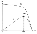
図2を参照して、MPPT22による直流電圧Vdcの制御について説明する。図2は、本実施形態に係る太陽電池3による発電の特性を示す特性図である。曲線Cviは、太陽電池3による発電における電圧−電流の相関関係を示す曲線である。曲線Cpは、太陽電池3による発電における電力の特性を示す曲線である。
With reference to FIG. 2, control of DC voltage Vdc by
MPPT22は、図2に示す曲線Cpにおいて最大電力となる最大電力点Pmmpの電圧(最大電力点電圧)Vmppを探す制御を行う。具体的には、以下の通りである。
The
まず、直流電圧Vdcは、ある適当な電圧値に制御されているものとする。MPPT22は、この電圧での直流電力量Pdcを計測する。
First, it is assumed that the DC voltage Vdc is controlled to an appropriate voltage value. The
次に、MPPT22は、直流電圧Vdcを予め決められた1段階分の電圧を昇圧(又は降圧)させる電圧増減信号Vnを出力する。これにより、直流電圧は、直流電圧制御部23の制御により、僅かに上昇(又は下降)する。
Next, the
MPPT22は、上昇後(又は下降後)の直流電力量Pdcを計測する。MPPT22は、前回計測した直流電力量Pdcと今回新たに計測した直流電力量Pdcを比較する。
The
今回新たに計測した直流電力量Pdcの方が多い場合は、MPPT22は、前回と同じ方向を示す電圧増減信号Vnを出力する。即ち、前回の電圧増減信号Vnが昇圧させる信号であれば、今回も電圧増減信号Vnを昇圧させる信号として出力する。前回の電圧増減信号Vnが降圧させる信号であれば、今回も電圧増減信号Vnを降圧させる信号として出力する。
When the DC power amount Pdc newly measured this time is larger, the
今回新たに計測した直流電力量Pdcの方が少ない場合は、MPPT22は、前回と異なる電圧増減信号Vnを出力する。即ち、前回の電圧増減信号Vnが昇圧させる信号であれば、今回は電圧増減信号Vnを降圧させる信号として出力する。前回の電圧増減信号Vnが降圧させる信号であれば、今回は電圧増減信号Vnを昇圧させる信号として出力する。
When the DC power amount Pdc newly measured this time is smaller, the
上記の手順を繰り返すことにより、MPPT22は、直流電圧Vdcが常に最大電力点電圧Vmppの近傍にあるように制御する。
By repeating the above procedure, the
電圧低下検知部26には、交流電圧検出器73により検出された系統電圧Vrが入力される。電圧低下検知部26は、系統電圧Vrに基づいて、直流電圧制御部23に検知信号Sdを出力する。電圧低下検知部26は、系統電圧Vrが所定の基準電圧以上の時(通常時)は、検知信号Sdを「0」にする。電圧低下検知部26は、系統電圧Vrが所定の基準電圧を下回ると(系統電圧Vrの低下時)、検知信号Sdを「1」にする。
The voltage
直流電圧制御部23には、直流電圧検出器74により検出された直流電圧Vdc、MPPT22から出力された電圧増減信号Vn、電圧低下検知部26から出力された検知信号Sd、及び電流制御部24により演算された電圧指令値Vivrが入力される。直流電圧制御部23は、検知信号Sdが「0」のときは、MPPT22による通常時の直流電圧Vdcの制御を行う。直流電圧制御部23は、検知信号Sdが「1」のときは、系統電圧Vrの低下時の直流電圧Vdcの制御を行う。直流電圧制御部23は、直流電圧Vdcを制御するための直流電圧指令値Vdcrを演算する。直流電圧制御部23は、演算した直流電圧指令値Vdcrを電流制御部24に出力する。
The DC
電流制御部24には、交流電流検出器71により検出された出力電流Iiv、電力量演算部21により演算された直流電力量Pdc、及び直流電圧制御部23により演算された直流電圧指令値Vdcrが入力される。電流制御部24は、出力電流Iiv、直流電力量Pdc、及び直流電圧指令値Vdcrに基づいて、インバータ1の出力電圧を制御するための電圧指令値Vivrを演算する。電流制御部24は、演算した電圧指令値VivrをPWM制御部25に出力する。
The
PWM制御部25には、電流制御部24により演算された電圧指令値Vivrが入力される。PWM制御部25は、インバータ1の出力電圧を電圧指令値Vivrに制御するためのゲート信号Gtを生成する。ゲート信号Gtは、インバータ1のスイッチング素子を駆動させる。これにより、インバータ1は、PWM制御される。
The voltage command value Vivr calculated by the
図3は、本実施形態に係る直流電圧制御部23の構成を示す構成図である。
FIG. 3 is a configuration diagram illustrating a configuration of the DC
直流電圧制御部23は、通常時直流電圧制御部231と、電圧低下時直流電圧制御部232とを備えている。検知信号Sdが「0」のときは、通常時直流電圧制御部231により直流電圧Vdcの制御がされる。検知信号Sdが「1」のときは、電圧低下時直流電圧制御部232により直流電圧Vdcの制御がされる。
The DC
通常時直流電圧制御部231には、直流電圧検出器74により検出された直流電圧Vdc、MPPT22から出力された電圧増減信号Vn、及び電圧低下検知部26から出力された検知信号Sdが入力される。通常時直流電圧制御部231は、「1」を示す検知信号Sdを受信すると、制御を停止する。このとき、通常時直流電圧制御部231は、停止直前に出力していた直流電圧指令値Vdcrを保持する。通常時直流電圧制御部231は、「0」を示す検知信号Sdを受信すると、制御を開始する。このとき、制御の停止時に保持していた直流電圧指令値Vdcrを出力する。その後、通常時直流電圧制御部231は、前述したMPPT22による制御に従って、直流電圧Vdcを制御する。
The direct
電圧低下時直流電圧制御部232には、直流電圧検出器74により検出された直流電圧Vdc、電圧低下検知部26から出力された検知信号Sd、電流制御部24により演算された電圧指令値Vivrが入力される。電圧低下時直流電圧制御部232は、「1」を示す検知信号Sdを受信すると、制御を開始する。電圧低下時直流電圧制御部232は、「0」を示す検知信号Sdを受信すると、制御を停止する。
The DC
電圧低下時直流電圧制御部232は、電流制御部24により演算された電圧指令値Vivrに基づいて、インバータ1の出力電流Iivのリプルが過電流継電器72の整定値を超えないように、直流電圧Vdcを昇圧させるための直流電圧指令値Vdcrを演算する。即ち、電圧低下時直流電圧制御部232は、インバータ1の出力電流Iivが所定値以下になるまで、直流電圧Vdcを昇圧し続ける。図2に示すように、最大電力点電圧Vmppよりも直流電圧Vdcを昇圧した場合、直流電流Idcは減少する。電圧低下時直流電圧制御部232は、インバータ1の出力電流Iivが所定値以下になった後は、系統電圧Vrが低下している間、直流電圧Vdcを維持する。
Based on the voltage command value Vivr calculated by the
本実施形態によれば、連系されている電力系統の系統電圧Vrが低下すると、直流電圧Vdcを昇圧する制御がされる。これにより、インバータ1に入力される直流電流Idcは減少する。従って、インバータ1の出力電流Iivも減少する。これにより、インバータ1の出力電流Iivのリプルによる過電流継電器72の不要動作を防止することができる。また、通常時は、MPPT22による直流電圧Vdcの制御をすることで、太陽電池3の発電効率を最大限に引き出すことができる。
According to the present embodiment, when the system voltage Vr of the interconnected power system is reduced, the DC voltage Vdc is controlled to be boosted. Thereby, the direct current Idc input to the
(第2の実施形態)
図4は、本発明の第2の実施形態に係るインバータ1の制御装置2Aを適用した太陽光発電システム10Aの構成を示す構成図である。(Second Embodiment)
FIG. 4 is a configuration diagram showing a configuration of a photovoltaic
太陽光発電システム10Aは、図1に示す第1の実施形態に係る太陽光発電システム10において、制御装置2を制御装置2Aに代えている。その他は、第1の実施形態に係る太陽光発電システム10と同様である。
In the solar
制御装置2Aは、第1の実施形態に係る制御装置2において、直流電圧制御部23を直流電圧制御部23Aに代え、電圧低下検知部26を電圧低下量演算部27に代えている。その他は、第1の実施形態に係る制御装置2と同様である。
In the
電圧低下量演算部27には、交流電圧検出器73により検出された系統電圧Vrが入力される。電圧低下量演算部27は、系統電圧Vrが所定の基準電圧を下回ると(系統電圧Vrの低下時)、定格電圧から系統電圧Vrを引いた電圧低下量ΔVを演算する。電圧低下量演算部27は、演算した電圧低下量ΔVを直流電圧制御部23Aに出力する。
The system voltage Vr detected by the
図5は、本実施形態に係る直流電圧制御部23Aの構成を示す構成図である。
FIG. 5 is a configuration diagram showing the configuration of the DC
直流電圧制御部23Aは、図3に示す第1の実施形態に係る直流電圧制御部23において、電圧低下時直流電圧制御部232を電圧低下時直流電圧制御部232Aに代えている。その他は、第1の実施形態に係る直流電圧制御部23と同様である。なお、本実施形態に係る通常時直流電圧制御部231は、第1の実施形態に係る検知信号Sdが「0」のときは、電圧低下量ΔVが「0」のとき(又は、電圧低下量ΔVが演算されていないとき)に相当し、第1の実施形態に係る検知信号Sdが「1」のときは、電圧低下量ΔVが「0」でないときに相当する。
In the DC
電圧低下時直流電圧制御部232Aには、直流電圧検出器74により検出された直流電圧Vdc及び電圧低下量演算部27により演算された電圧低下量ΔVが入力される。電圧低下時直流電圧制御部232Aは、電圧低下量ΔVが「0」でない場合(系統電圧Vrの低下時)、制御を開始する。電圧低下時直流電圧制御部232Aは、電圧低下量ΔVが「0」の場合(通常時)、制御を停止する。
A DC voltage Vdc detected by the
電圧低下時直流電圧制御部232Aは、系統電圧Vrの低下時、電圧低下量ΔVに基づいて、直流電圧指令値Vdcrを演算する。電圧低下時直流電圧制御部232Aは、電圧低下量ΔVが大きい程、直流電圧指令値Vdcrが大きい値になるように演算する。即ち、電圧低下時直流電圧制御部232Aは、電圧低下量ΔVが大きい程、直流電圧Vdcを大きく昇圧する。これにより、電圧低下時直流電圧制御部232Aは、電圧低下量ΔVに応じて、インバータ1の出力電流Iivを減少させる。
The voltage drop direct current
次に、系統電圧Vrの低下時の直流電圧指令値Vdcrの演算方法について説明する。 Next, a method for calculating the DC voltage command value Vdcr when the system voltage Vr is lowered will be described.
インバータ1の出力電流Iivに重畳される電流リプルは、次式に基づいて発生する。
The current ripple superimposed on the output current Iiv of the
di/dt=ΔV/L …式(1)
ここで、左辺は、インバータ1の出力電流Iivの変化率である。Lは、インバータ1と系統母線7との間のリアクトル成分である。ΔVは、系統電圧Vrの電圧低下量である。di / dt = ΔV / L (1)
Here, the left side is the rate of change of the output current Iiv of the
直流電圧指令値Vdcrは、上記の式に基づいて予測される電流リプルを抑制するように設定される。 The DC voltage command value Vdcr is set so as to suppress the current ripple predicted based on the above formula.
本実施形態によれば、系統電圧Vrの電圧低下量ΔVに応じて、直流電圧Vdcを昇圧する制御がされる。従って、第1の実施形態と同様の作用効果を得ることができる。 According to the present embodiment, control for boosting the DC voltage Vdc is performed in accordance with the voltage drop amount ΔV of the system voltage Vr. Therefore, the same effect as the first embodiment can be obtained.
なお、各実施形態では、インバータ1の直流電圧Vdcを上昇させて、インバータ1の出力電流Iivを抑制したが、直流電圧Vdcを降圧させて、出力電流Iivを抑制する制御をしてもよい。図2に示す最大電力点電圧Vmppを外すように、直流電圧Vdcを制御することで、出力電流Iivを抑制する制御をすることができる。これにより、各実施形態と同様の作用効果を得ることができる。
In each embodiment, the DC voltage Vdc of the
また、第2の実施形態において、系統電圧Vrの低下時の直流電圧指令値Vdcrを求める式は、上記(1)式に基づかなくてもよい。例えば、直流電圧指令値Vdcrを求める式は、経験則又はノウハウによって求めてもよい。 In the second embodiment, the formula for obtaining the DC voltage command value Vdcr when the system voltage Vr is lowered may not be based on the formula (1). For example, the formula for obtaining the DC voltage command value Vdcr may be obtained by empirical rules or know-how.
さらに、各実施形態において、太陽光発電システム10と交流電力系統との間に設けられた連系トランス6は無くてもよい。この場合、交流電圧検出器73により検出される電圧は、交流電流検出器71により検出される電流と同じ測定箇所の電気量になる。
Furthermore, in each embodiment, the interconnection transformer 6 provided between the solar
なお、本発明は上記実施形態そのままに限定されるものではなく、実施段階ではその要旨を逸脱しない範囲で構成要素を変形して具体化できる。また、上記実施形態に開示されている複数の構成要素の適宜な組み合わせにより、種々の発明を形成できる。例えば、実施形態に示される全構成要素から幾つかの構成要素を削除してもよい。さらに、異なる実施形態にわたる構成要素を適宜組み合わせてもよい。 Note that the present invention is not limited to the above-described embodiment as it is, and can be embodied by modifying the constituent elements without departing from the scope of the invention in the implementation stage. In addition, various inventions can be formed by appropriately combining a plurality of components disclosed in the embodiment. For example, some components may be deleted from all the components shown in the embodiment. Furthermore, constituent elements over different embodiments may be appropriately combined.
本発明によれば、交流電力系統と連系し、交流電力系統側に設けられた過電流継電器の不要動作を防止することのできる太陽光発電システムを提供することを提供することができる。 ADVANTAGE OF THE INVENTION According to this invention, it can provide providing the photovoltaic power generation system which can prevent the unnecessary operation | movement of the overcurrent relay provided in the alternating current power system side in connection with an alternating current power system.
Claims (15)
太陽電池と、
前記太陽電池により発電された直流電力を交流電力に変換するインバータと、
前記交流電力系統の系統電圧を計測する系統電圧計測手段と、
前記系統電圧計測手段により計測された系統電圧に基づいて、前記交流電力系統の電圧低下を検出する電圧低下検出手段と、
前記電圧低下検出手段による電圧低下が検出されていない場合、前記太陽電池による発電が最大電力点になるように、前記インバータの直流電圧を制御する第1の直流電圧制御手段と、
前記電圧低下検出手段による電圧低下が検出された場合、前記インバータの出力側に設けられた過電流継電器の整定値を前記インバータから出力される電流のリプルが超えないように、前記インバータの直流電圧を制御する第2の直流電圧制御手段と
を備えたことを特徴とする太陽光発電システム。 A photovoltaic power generation system linked to an AC power system,
Solar cells,
An inverter that converts DC power generated by the solar cell into AC power;
System voltage measuring means for measuring the system voltage of the AC power system;
Based on the system voltage measured by the system voltage measurement unit, a voltage drop detection unit that detects a voltage drop of the AC power system;
First voltage control means for controlling the DC voltage of the inverter so that power generation by the solar cell is at the maximum power point when no voltage drop by the voltage drop detection means is detected;
When a voltage drop is detected by the voltage drop detecting means, the DC voltage of the inverter is set so that the ripple of the current output from the inverter does not exceed the set value of the overcurrent relay provided on the output side of the inverter. And a second direct-current voltage control means for controlling the solar power generation system.
を特徴とする請求項1に記載の太陽光発電システム。 2. The photovoltaic power generation system according to claim 1, wherein the second DC voltage control unit performs control to increase a DC voltage of the inverter when a voltage drop is detected by the voltage drop detection unit. .
を特徴とする請求項2に記載の太陽光発電システム。 3. The second DC voltage control means, when a voltage drop is detected by the voltage drop detection means, changes a voltage amount for boosting a DC voltage of the inverter according to the voltage drop amount. The photovoltaic power generation system described in 1.
を特徴とする請求項1に記載の太陽光発電システム。 2. The photovoltaic power generation system according to claim 1, wherein the second DC voltage control unit performs control to step down a DC voltage of the inverter when a voltage drop is detected by the voltage drop detection unit. .
を特徴とする請求項4に記載の太陽光発電システム。 5. The second DC voltage control means, when a voltage drop is detected by the voltage drop detection means, changes a voltage amount for stepping down the DC voltage of the inverter according to the voltage drop amount. The photovoltaic power generation system described in 1.
前記交流電力系統の系統電圧を計測する系統電圧計測手段と、
前記系統電圧計測手段により計測された系統電圧に基づいて、前記交流電力系統の電圧低下を検出する電圧低下検出手段と、
前記電圧低下検出手段による電圧低下が検出されていない場合、前記太陽電池による発電が最大電力点になるように、前記インバータの直流電圧を制御する第1の直流電圧制御手段と、
前記電圧低下検出手段による電圧低下が検出された場合、前記インバータの出力側に設けられた過電流継電器の整定値を前記インバータから出力される電流のリプルが超えないように、前記インバータの直流電圧を制御する第2の直流電圧制御手段と
を備えたことを特徴とするインバータの制御装置。 An inverter control device for controlling an inverter applied to a solar power generation system including a solar cell connected to an AC power system,
System voltage measuring means for measuring the system voltage of the AC power system;
Based on the system voltage measured by the system voltage measurement unit, a voltage drop detection unit that detects a voltage drop of the AC power system;
First voltage control means for controlling the DC voltage of the inverter so that power generation by the solar cell is at the maximum power point when no voltage drop by the voltage drop detection means is detected;
When a voltage drop is detected by the voltage drop detecting means, the DC voltage of the inverter is set so that the ripple of the current output from the inverter does not exceed the set value of the overcurrent relay provided on the output side of the inverter. And a second DC voltage control means for controlling the inverter.
を特徴とする請求項6に記載のインバータの制御装置。 7. The inverter control device according to claim 6, wherein the second DC voltage control means controls to increase the DC voltage of the inverter when a voltage drop is detected by the voltage drop detection means. .
を特徴とする請求項7に記載のインバータの制御装置。 8. The second DC voltage control means, when a voltage drop is detected by the voltage drop detection means, changes a voltage amount for boosting the DC voltage of the inverter according to the voltage drop amount. The inverter control device described in 1.
を特徴とする請求項6に記載のインバータの制御装置。 7. The inverter control device according to claim 6, wherein the second DC voltage control means controls to step down a DC voltage of the inverter when a voltage drop is detected by the voltage drop detection means. .
を特徴とする請求項9に記載のインバータの制御装置。 10. The second DC voltage control means, when a voltage drop is detected by the voltage drop detection means, changes a voltage amount for stepping down the DC voltage of the inverter according to the voltage drop amount. The inverter control device described in 1.
前記交流電力系統の系統電圧を計測し、
計測した系統電圧に基づいて、前記交流電力系統の電圧低下を検出し、
前記交流電力系統の電圧低下を検出していない場合、前記太陽電池による発電が最大電力点になるように、前記インバータの直流電圧を制御し、
前記交流電力系統の電圧低下を検出した場合、前記インバータの出力側に設けられた過電流継電器の整定値を前記インバータから出力される電流のリプルが超えないように、前記インバータの直流電圧を制御すること
を含むことを特徴とするインバータの制御方法。 An inverter control method for controlling an inverter applied to a solar power generation system including a solar cell connected to an AC power system,
Measure the system voltage of the AC power system,
Based on the measured system voltage, the voltage drop of the AC power system is detected,
When the voltage drop of the AC power system is not detected, the DC voltage of the inverter is controlled so that the power generation by the solar cell becomes the maximum power point ,
When a voltage drop in the AC power system is detected, the DC voltage of the inverter is controlled so that the ripple of the current output from the inverter does not exceed the set value of the overcurrent relay provided on the output side of the inverter. And a method for controlling an inverter.
を含むことを特徴とする請求項11に記載のインバータの制御方法。 The method for controlling an inverter according to claim 11, further comprising controlling to increase a DC voltage of the inverter when a voltage drop of the AC power system is detected.
を含むことを特徴とする請求項12に記載のインバータの制御方法。 13. The inverter control method according to claim 12, further comprising: changing a voltage amount for boosting the DC voltage of the inverter according to the voltage drop amount when a voltage drop in the AC power system is detected.
を含むことを特徴とする請求項11に記載のインバータの制御方法。 The method for controlling an inverter according to claim 11, further comprising a control for stepping down a DC voltage of the inverter when a voltage drop of the AC power system is detected.
を含むことを特徴とする請求項14に記載のインバータの制御方法。 The method for controlling an inverter according to claim 14, further comprising: changing a voltage amount for boosting a DC voltage of the inverter according to a voltage drop amount when a voltage drop in the AC power system is detected.
Applications Claiming Priority (1)
| Application Number | Priority Date | Filing Date | Title |
|---|---|---|---|
| PCT/JP2011/053958 WO2012114469A1 (en) | 2011-02-23 | 2011-02-23 | Solar power generation system |
Publications (2)
| Publication Number | Publication Date |
|---|---|
| JPWO2012114469A1 JPWO2012114469A1 (en) | 2014-07-07 |
| JP5659290B2 true JP5659290B2 (en) | 2015-01-28 |
Family
ID=46720288
Family Applications (1)
| Application Number | Title | Priority Date | Filing Date |
|---|---|---|---|
| JP2013500765A Active JP5659290B2 (en) | 2011-02-23 | 2011-02-23 | Solar power system |
Country Status (6)
| Country | Link |
|---|---|
| US (1) | US9300226B2 (en) |
| EP (1) | EP2680426B1 (en) |
| JP (1) | JP5659290B2 (en) |
| CN (1) | CN103392292B (en) |
| ES (1) | ES2893307T3 (en) |
| WO (1) | WO2012114469A1 (en) |
Families Citing this family (6)
| Publication number | Priority date | Publication date | Assignee | Title |
|---|---|---|---|---|
| US9722458B2 (en) * | 2013-10-15 | 2017-08-01 | Toshiba Mitsubishi-Electric Industrial Systems Corporation | Power conversion device and method of controlling the same |
| EP3086457B1 (en) | 2013-12-20 | 2022-06-15 | Toshiba Mitsubishi-Electric Industrial Systems Corporation | Inverter control device |
| EP2922193A1 (en) | 2014-03-20 | 2015-09-23 | Panasonic Intellectual Property Management Co., Ltd. | Power conversion apparatus and control method for power conversion apparatus |
| JP6378572B2 (en) * | 2014-07-30 | 2018-08-22 | 株式会社日立産機システム | Power conversion control device and photovoltaic power generation system |
| JP6153144B1 (en) * | 2016-03-17 | 2017-06-28 | 三菱電機株式会社 | Control device and control method for DC / DC converter |
| US20220376632A1 (en) * | 2020-10-08 | 2022-11-24 | Toshiba Mitsubishi-Electric Industrial Systems Corporation | Power conversion device |
Citations (4)
| Publication number | Priority date | Publication date | Assignee | Title |
|---|---|---|---|---|
| JP2004328831A (en) * | 2003-04-22 | 2004-11-18 | Mitsubishi Electric Corp | Voltage fluctuation compensation device |
| JP2008059968A (en) * | 2006-09-01 | 2008-03-13 | Matsushita Electric Ind Co Ltd | Fuel cell system |
| JP2008228494A (en) * | 2007-03-14 | 2008-09-25 | Kansai Electric Power Co Inc:The | Inverter for coordinating system |
| JP2009165265A (en) * | 2008-01-07 | 2009-07-23 | Mitsubishi Electric Corp | Power converter |
Family Cites Families (12)
| Publication number | Priority date | Publication date | Assignee | Title |
|---|---|---|---|---|
| JP2736102B2 (en) * | 1989-02-17 | 1998-04-02 | 株式会社東芝 | Control device of power converter for grid connection |
| JP2001136664A (en) * | 1999-11-05 | 2001-05-18 | Hitachi Ltd | Distributed power generating system |
| CN1334985A (en) * | 1999-11-29 | 2002-02-06 | 三菱电机株式会社 | Inverter controller |
| JP2002165357A (en) * | 2000-11-27 | 2002-06-07 | Canon Inc | Power converter and its control method, and power generating system |
| US6921985B2 (en) | 2003-01-24 | 2005-07-26 | General Electric Company | Low voltage ride through for wind turbine generators |
| US7193872B2 (en) * | 2005-01-28 | 2007-03-20 | Kasemsan Siri | Solar array inverter with maximum power tracking |
| US8405367B2 (en) * | 2006-01-13 | 2013-03-26 | Enecsys Limited | Power conditioning units |
| CN101304221B (en) * | 2008-06-19 | 2011-09-28 | 江苏津恒能源科技有限公司 | Solar photovoltaic interconnected inverter |
| WO2010148009A2 (en) * | 2009-06-15 | 2010-12-23 | Tenksolar, Inc. | Illumination agnostic solar panel |
| US8228697B2 (en) * | 2009-07-20 | 2012-07-24 | General Electric Company | Systems, methods, and apparatus for operating a power converter |
| CN102082443B (en) * | 2009-11-27 | 2013-10-02 | 通用电气公司 | Direct current (DC)-alternating current (AC) converting system and method |
| CN101777775A (en) * | 2010-02-26 | 2010-07-14 | 东南大学 | High-frequency isolation single-phase photovoltaic grid-connected system and control method thereof |
-
2011
- 2011-02-23 WO PCT/JP2011/053958 patent/WO2012114469A1/en active Application Filing
- 2011-02-23 JP JP2013500765A patent/JP5659290B2/en active Active
- 2011-02-23 EP EP11859348.2A patent/EP2680426B1/en active Active
- 2011-02-23 CN CN201180068310.1A patent/CN103392292B/en active Active
- 2011-02-23 ES ES11859348T patent/ES2893307T3/en active Active
-
2013
- 2013-08-22 US US13/973,641 patent/US9300226B2/en active Active
Patent Citations (4)
| Publication number | Priority date | Publication date | Assignee | Title |
|---|---|---|---|---|
| JP2004328831A (en) * | 2003-04-22 | 2004-11-18 | Mitsubishi Electric Corp | Voltage fluctuation compensation device |
| JP2008059968A (en) * | 2006-09-01 | 2008-03-13 | Matsushita Electric Ind Co Ltd | Fuel cell system |
| JP2008228494A (en) * | 2007-03-14 | 2008-09-25 | Kansai Electric Power Co Inc:The | Inverter for coordinating system |
| JP2009165265A (en) * | 2008-01-07 | 2009-07-23 | Mitsubishi Electric Corp | Power converter |
Also Published As
| Publication number | Publication date |
|---|---|
| EP2680426A4 (en) | 2017-11-22 |
| CN103392292A (en) | 2013-11-13 |
| ES2893307T3 (en) | 2022-02-08 |
| US20130336030A1 (en) | 2013-12-19 |
| CN103392292B (en) | 2016-02-10 |
| US9300226B2 (en) | 2016-03-29 |
| JPWO2012114469A1 (en) | 2014-07-07 |
| EP2680426B1 (en) | 2021-07-21 |
| EP2680426A1 (en) | 2014-01-01 |
| WO2012114469A1 (en) | 2012-08-30 |
Similar Documents
| Publication | Publication Date | Title |
|---|---|---|
| JP5681785B2 (en) | Power converter | |
| JP6031609B2 (en) | Control device for inverter for photovoltaic power generation | |
| JP6166832B1 (en) | Power interconnection device for grid connection and output current control method thereof | |
| JP5659290B2 (en) | Solar power system | |
| JP5608809B2 (en) | Power converter | |
| JP6762680B2 (en) | Solar power system | |
| JP2005269843A (en) | Parallel operation device | |
| JP6366083B2 (en) | Inverter control device | |
| JP5294908B2 (en) | Power converter | |
| JP5528730B2 (en) | Power converter | |
| JP6220895B2 (en) | Inverter control device | |
| JP2005192317A (en) | Inverter device for interconnected system | |
| Horta et al. | DC Bus based microgrid for buildings applications |
Legal Events
| Date | Code | Title | Description |
|---|---|---|---|
| A521 | Request for written amendment filed |
Free format text: JAPANESE INTERMEDIATE CODE: A523 Effective date: 20140421 |
|
| TRDD | Decision of grant or rejection written | ||
| A01 | Written decision to grant a patent or to grant a registration (utility model) |
Free format text: JAPANESE INTERMEDIATE CODE: A01 Effective date: 20141104 |
|
| A61 | First payment of annual fees (during grant procedure) |
Free format text: JAPANESE INTERMEDIATE CODE: A61 Effective date: 20141201 |
|
| R150 | Certificate of patent or registration of utility model |
Ref document number: 5659290 Country of ref document: JP Free format text: JAPANESE INTERMEDIATE CODE: R150 |
|
| R250 | Receipt of annual fees |
Free format text: JAPANESE INTERMEDIATE CODE: R250 |
|
| R250 | Receipt of annual fees |
Free format text: JAPANESE INTERMEDIATE CODE: R250 |
|
| R250 | Receipt of annual fees |
Free format text: JAPANESE INTERMEDIATE CODE: R250 |
|
| R250 | Receipt of annual fees |
Free format text: JAPANESE INTERMEDIATE CODE: R250 |
|
| R250 | Receipt of annual fees |
Free format text: JAPANESE INTERMEDIATE CODE: R250 |
|
| R250 | Receipt of annual fees |
Free format text: JAPANESE INTERMEDIATE CODE: R250 |
|
| R250 | Receipt of annual fees |
Free format text: JAPANESE INTERMEDIATE CODE: R250 |