JP5659044B2 - Contact lens case - Google Patents
Contact lens case Download PDFInfo
- Publication number
- JP5659044B2 JP5659044B2 JP2011042857A JP2011042857A JP5659044B2 JP 5659044 B2 JP5659044 B2 JP 5659044B2 JP 2011042857 A JP2011042857 A JP 2011042857A JP 2011042857 A JP2011042857 A JP 2011042857A JP 5659044 B2 JP5659044 B2 JP 5659044B2
- Authority
- JP
- Japan
- Prior art keywords
- case
- contact lens
- main body
- hinge
- ring body
- Prior art date
- Legal status (The legal status is an assumption and is not a legal conclusion. Google has not performed a legal analysis and makes no representation as to the accuracy of the status listed.)
- Expired - Fee Related
Links
Images
Landscapes
- Purses, Travelling Bags, Baskets, Or Suitcases (AREA)
Description
本発明は、コンタクトレンズケースに関するものである。 The present invention relates to a contact lens case.
この種のコンタクトレンズケースとして、従来、例えば下記特許文献1に示されているような、ケア剤容器(ボトル)のキャップに着脱可能なコンタクトレンズケースが知られている。このコンタクトレンズケースは、コンタクトレンズを収容する凹状の収容部を有するケース本体部と、ケース本体部にヒンジを介して連結されて収容部に被着される開閉可能な蓋部と、が備えられている。ケース本体部は、左右のコンタクトレンズを別々に収容できるように、基台部に一対の収容部が並設されている。
また、基台部の中間部分には、ケア剤容器のキャップの鍔部に対して嵌合可能な嵌合凹部が形成されている。このコンタクトレンズケースによれば、蓋部を開けると共にケース本体部を裏返した姿勢で前記嵌合凹部をケア剤容器のキャップの鍔部に嵌合させることで、裏返した姿勢で保持される。これにより、収容部の内側や蓋部の裏面の液切れが良くなり、水洗後のコンタクトレンズケースを良好に自然乾燥させることができる。
As this type of contact lens case, a contact lens case that can be attached to and detached from a cap of a care agent container (bottle) as shown in, for example,
Moreover, the fitting recessed part which can be fitted with respect to the collar part of the cap of a care agent container is formed in the intermediate part of the base part. According to this contact lens case, the lid is opened and the fitting main body is turned upside down so that the fitting recess is fitted to the collar portion of the cap of the care agent container, so that the contact lens case is held upside down. Thereby, the drainage of the inner side of the housing part and the back surface of the lid part is improved, and the contact lens case after water washing can be naturally dried well.
しかしながら、上記した特許文献1のコンタクトレンズケースでは、ケア剤容器の上蓋の鍔部の形状に嵌合凹部を嵌合させる構成であるため、その嵌合凹部に対応した形状の鍔部を有するケア剤容器のみの使用となり、適用可能な形状のケア剤容器が限定されてしまうという問題があった。そのため、ケア剤容器(ボトル)の形状に依存されることなく、種々の異なる形状のケア剤容器に対して共通に装着して自然乾燥できるコンタクトレンズケースが求められており、その点で改良の余地があった。
However, since the contact lens case of
本発明は、このような事情に鑑みてなされたものであって、ボトル形状に依存されることなく、種々の形状のボトルに対して装着して自然乾燥を行うことができるコンタクトレンズケースを提供することを目的とする。 The present invention has been made in view of such circumstances, and provides a contact lens case that can be naturally dried by being attached to bottles of various shapes without depending on the bottle shape. The purpose is to do.
上記の目的を達成するために、この発明は以下の手段を提供している。
本発明に係るコンタクトレンズケースは、コンタクトレンズ及び薬液を収容する凹状の第一及び第二収容部が並設されたケース本体部と、該ケース本体部に第二ヒンジを介して連結されて前記第一及び第二収容部を開閉可能な蓋部と、前記ケース本体部に第一ヒンジを介して連結されるとともに、前記薬液が収容されたボトルに着脱自在に嵌合されるリング体と、が備えられ、前記第一ヒンジ及び前記第二ヒンジは、平面視で対向するように配置されていることを特徴としている。
In order to achieve the above object, the present invention provides the following means.
The contact lens case according to the present invention includes a case main body part in which concave and first concave and negative container parts for containing a contact lens and a chemical solution are juxtaposed, and the case main body part connected to the case main body part via a second hinge. A lid that can open and close the first and second storage portions, a ring body that is connected to the case main body portion via a first hinge and is detachably fitted to the bottle containing the chemical solution; The first hinge and the second hinge are arranged to face each other in plan view .
このような特徴により、コンタクトレンズケースの第一及び第二収容部を自然に乾燥させる際には、蓋部を開いた状態で、第一及び第二収容部の開口側が下向きとなるようにケース本体部を上下に反転させた姿勢にしてリング体をボトルの口部などに嵌合することが可能となる。これにより、ケース本体部がボトルに対して裏返しの姿勢で保持され、第一及び第二収容部を下向きの状態で自然乾燥させることができる。 With such a feature, when the first and second housing parts of the contact lens case are naturally dried, the case is so that the opening side of the first and second housing parts faces downward with the lid part opened. The ring body can be fitted to the mouth of the bottle or the like with the main body portion turned upside down. Thereby, a case main-body part is hold | maintained with the attitude | position reversed inside with respect to a bottle, and a 1st and 2nd accommodating part can be naturally dried in a downward state.
なお、例えばリング体をC型状とすれば、径方向の開口部分を周方向に拡げることも可能となるので、口部などの大きさ、形状が異なる複数種のボトルに対しても容易に装着することができる。 For example, if the ring body is C-shaped, it is possible to expand the opening portion in the radial direction in the circumferential direction, so it can be easily applied to a plurality of types of bottles having different sizes and shapes such as mouth portions. Can be installed.
また、リング体は第一ヒンジを介してケース本体部に連結されており、リング体とケース本体部との相対角度を変更することができるので、ケース本体部をボトルの外面形状に沿わせた姿勢にして配置することができる。これにより、ボトルにリング体を装着させたケース本体部をボトルの外面上に預けて支持させることで、ケース本体部の姿勢の安定感を向上させることができる。
このように、本コンタクトレンズケースでは、ボトル形状に依存することなく、種々の形状のボトルに対しても使用することが可能となり、汎用性を高めることができる。
Also, the ring body is connected to the case main body via the first hinge, and the relative angle between the ring body and the case main body can be changed, so that the case main body is made to conform to the outer surface shape of the bottle. It can be placed in a posture. Thereby, the stability of the attitude | position of a case main-body part can be improved by depositing and supporting the case main-body part which attached the ring body to the bottle on the outer surface of a bottle.
Thus, this contact lens case can be used for bottles of various shapes without depending on the bottle shape, and versatility can be improved.
さらに、第一及び第二収容部の開口側を上向きにしてリング体をボトルに嵌合させることも可能である。そのため、水洗いした後などの自然乾燥時だけでなく、保存・消毒時にも本コンタクトレンズケースをボトルに装着して使用することができる。この場合、第一及び第二収容部にレンズ及び薬液を入れたケース本体部を蓋部で閉じた姿勢で装着することが可能である。 Furthermore, it is also possible to fit the ring body to the bottle with the opening sides of the first and second housing portions facing upward. For this reason, the contact lens case can be used by being attached to a bottle not only during natural drying such as after washing with water but also during storage and disinfection. In this case, it is possible to attach the case main body portion in which the lens and the chemical solution are put in the first and second storage portions in a posture closed by the lid portion.
また、上記本発明のコンタクトレンズケースでは、前記ケース本体部には、前記第一及び第二収容部の底部側で前記リング体を保持する係止片が設けられていることが好ましい。 In the contact lens case of the present invention, it is preferable that the case main body portion is provided with a locking piece for holding the ring body on the bottom side of the first and second housing portions.
この場合には、リング体を第一ヒンジで回転させて第一及び第二収容部の底部側へ畳み込んで係止片に係止させて保持することで、そのリング体を第一及び第二収容部の底部側部分に収容することができる。そのため、リング体がケース本体より外側に張り出されることがなく、携帯したり保管したりするのに好適となる利点がある。 In this case, the ring body is rotated by the first hinge, folded to the bottom side of the first and second accommodating portions, and held by being locked to the locking pieces, whereby the ring body is held in the first and second directions. It can be accommodated in the bottom side portion of the two accommodating portions. Therefore, there is an advantage that the ring body does not protrude outward from the case body, and is suitable for carrying or storing.
本発明に係るコンタクトレンズケースによれば、ボトル形状に依存されることなく、種々の形状のボトルに対して装着して自然乾燥を行うことができる。 The contact lens case according to the present invention can be naturally dried by being attached to bottles of various shapes without depending on the bottle shape.
以下、本発明に係るコンタクトレンズケースの実施形態について図面を参照して説明する。
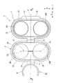
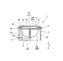
図1及び図2に示すように、本実施形態のコンタクトレンズケース1は、コンタクトレンズを保管するための合成樹脂からなるプラスチック容器であり、その概略構成としては、コンタクトレンズ及び保存液、消毒液などの薬液を収容する凹状の第一収容部20R及び第二収容部20Lが並設されたケース本体部2と、ケース本体部2に第二ヒンジ6を介して連結されて第一収容部20R及び第二収容部20Lを開閉可能な蓋部3と、ケース本体部2に第一ヒンジ5を介して連結されるとともに薬液が収容されたボトル10(図6参照)に着脱自在に嵌合されるリング体4と、を備えている。
Hereinafter, embodiments of a contact lens case according to the present invention will be described with reference to the drawings.
As shown in FIGS. 1 and 2, the
ここで、図1において、第一収容部20R及び第二収容部20Lの中心軸線をそれぞれO1、O2としている。尚、中心軸線O1、O2は平行に配置されている。また、図1に示す符号Cは、平面視で前記2つの中心軸線O1、O2に直交し、その間を結ぶ直線Qの中心を通るとともに、その直線Qに直交する容器中心線を示している。さらに、本実施形態では、平面視において、第一収容部20R及び第二収容部20Lの並び方向(直線Qに沿って平行な方向)を「左右方向X」とし、その左右方向Xに直交する方向(容器中心線Cに沿って平行な方向)を「前後方向Y」とする。図1において、前後方向Yに沿って前記リング体4が張り出される(ケース本体部2の外方に回動されてケース本体部2から露出された状態)側を前側といい、その反対側を後側という。また、上記した中心軸線O1、O2に沿った方向を「上下方向Z」とし、図2において上下方向Zに沿って第一、第二収容部20R、20Lの開口縁側を上側といい、その反対側(底部側)を下側という。
Here, in FIG. 1, the central axes of the
図1及び図2に示すように、ケース本体部2は、開口を下側に向けた有頂筒状に形成されており、平板状の本体天壁部21と、本体天壁部21の外周縁端部で一体連結する本体周壁部22と、その本体天壁部21において左右方向Xに所定間隔をあけて並設されるとともに、略半球状に窪んで上側に向けて開口した前記第一収容部20R及び第二収容部20Lと、本体天壁部21から下方へ向けて突出する一対の係止片23、23と、を備えている。
As shown in FIGS. 1 and 2, the case
そして、本体天壁部21の後側部分には、本体天壁部21の上側に被着される開閉可能な蓋部3が第二ヒンジ6を介して連結されている。そのため、蓋部3を前側から後側に向かって回動させて開放することで、第一収容部20R及び第二収容部20Lの左右位置が明確に規定され、直感的に左右の視認性を高めることができる。
また、図3に示すように、本体周壁部22の左右方向X中央において、その前方下端部には、切欠き凹部22aが設けられ、この切欠き凹部22aの上端部に第一ヒンジ5を介してリング体4が左右方向Xの軸回りに回転可能に連結されている。なお、これら第一ヒンジ5及び第二ヒンジ6は、容器中心線C上でケース本体部2において対向するように配置されている。
An openable /
Further, as shown in FIG. 3, a
そして、本体天壁部21には、第一収容部20R及び第二収容部20Lの両者を一体に囲うようにして全周にわたって延びる係合凸部24が上方に向けて突設されている。
また、本体天壁部21には、2つの中心軸線O1、O2を結ぶ直線Q上に沿って延びるとともに、第一収容部20Rと第二収容部20Lの収容部分同士を連通する連通溝25が設けられている。
これによって、第一収容部20R及び第二収容部20Lの一方に薬液を注ぐだけで、他方にも薬液が充満される。
The main body
In addition, the main body
Thereby, the chemical solution is filled into the other only by pouring the chemical solution into one of the
第一収容部20R及び第二収容部20Lは、図2に示す縦断面視で半円弧状に形成されたボール皿状の皿部であり、これらの内側にはコンタクトレンズケア用の薬液が入れられた状態でコンタクトレンズが収容可能である。
この第一収容部20R及び第二収容部20Lの底面中央部分20aは、薄肉部となっており、その底面(内表面および/または外表面)には例えば彫刻、シボ、レーザー印字等の加飾が施されている。これにより、図1に示すように上方から左右を認識できるのは勿論、図4に示すように下面側からでも前記加飾を透かして見ることができるので左右が認識しやすくなる。
The
The
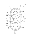
図4及び図5に示すように、一対の係止片23、23は、それぞれ本体天壁部21から下方に延びる棒状部材であり、その平面視の位置はリング体4の内周面4aに外接する位置であって、容器中心線Cを挟んで左右対称位置に設けられている。なお、係止片23の下端は、本体周壁部22の下端より上方に位置している。そして、係止片23の下端部には、アンダーカット嵌合用の凹部23aが形成され、この凹部23aにリング体4が嵌合されて保持される。
As shown in FIGS. 4 and 5, each of the pair of locking
図5に示すように、蓋部3は、第二ヒンジ6を介して本体天壁部21の外周上縁部に連結されており、有頂筒状に形成され、蓋天壁部31の外周縁から下方(蓋部3の裏側)に向けて延びるとともにケース本体部2の係合凸部24に外嵌する蓋周壁部32が設けられている(図1及び図2参照)。
As shown in FIG. 5, the
蓋天壁部31の外周縁部には、全周にわたって延びるシール部33が下方に向けて突設されている。このシール部33は、蓋周壁部32の内側に配設され、係合凸部24の内側に嵌合される。
また、シール部33の径方向内側には、図5に示すように、第一収容部20R及び第二収容部20Lの中心軸線O1、O2と同軸に設けられ、それら第一収容部20R及び第二収容部20L着脱自在に嵌合する筒状部34R、34Lが下方に向けて突設されている。
On the outer peripheral edge portion of the lid
Further, as shown in FIG. 5, the
また、蓋周壁部32の下端には、前後方向Yで第二ヒンジ6と反対側の部分から外側に突出した平板状のフランジからなる鍔部35が設けられている。この鍔部35は、図5に示すように、蓋部3が閉じられた状態においてケース天壁部21の前端上側に配置される。
なお、蓋部3をケース本体部2に連結する第二ヒンジ6は、左右方向Xの全長にわたって延在する溝が形成された折曲げ可能な板部であり、蓋部3を90度以上の角度で開くことができる。
In addition, at the lower end of the lid
The
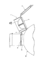
リング体4は、リング体4の中心(径方向の中央)が容器中心線C上に設けられ、その張り出し状態において前側に部分的な開口を有するC型状に形成されている。このリング体4は、第一ヒンジ5によって左右方向Xのヒンジ軸回りに回転し、図2に示す第一位置P1からケース本体部2の下側となる収容位置(図5に示す第二位置P2)まで回転可能となっている。なお、リング体4は、第一位置P1と第二位置P2との間の回転移動時において、その中心が容器中心線C上に沿って移動する。
The ring body 4 is formed in a C shape in which the center (diameter center) of the ring body 4 is provided on the container center line C and has a partial opening on the front side in the overhanging state. The ring body 4 is rotated about the hinge axis in the left-right direction X by the
リング体4をケース本体部2に連結する第一ヒンジ5は、左右方向Xの全長にわたって延在する溝が形成された折曲げ可能な板部であり、リング体4を略180度の開閉角度で折り曲げることができ、180度で折り曲げた状態(第二位置P2)でケース本体部2の下面側で本体周壁部22の内側に収容させることが可能となっている。
但し、この開閉可能な角度範囲は限定されるものではない。
The
However, the angle range that can be opened and closed is not limited.
次に、上述したように構成されたコンタクトレンズケース1の作用について説明する。
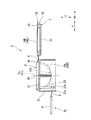
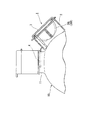
図1に示すように、コンタクトレンズケース1を水洗いなどした後に第一及び第二収容部20R、20Lを自然乾燥させる際には、蓋部3を開いた状態にするとともに、リング体4を第一ヒンジ5のヒンジ軸回りに回転させて第一位置P1でケース本体部2から張り出した状態にする。そして、図6に示すように、第一及び第二収容部20R、20Lの開口側が下向きとなるようにケース本体部2を上下に反転させた姿勢にしてリング体4をボトル10の口部11に嵌合させる。このとき、リング体4は、C型状の開口部から口部11に外嵌させることになる。これにより、ケース本体部2がボトル10に対して裏返しの姿勢で保持され、第一及び第二収容部20R、20Lを下向きの状態にして自然乾燥させることができる。そのため、第一及び第二収容部20R、20Lの内部の液切れが良くなり、良好な自然乾燥を行うことができる。
Next, the operation of the
As shown in FIG. 1, when the first and
また、リング体4がC型形状であるため、径方向の開口部分を周方向に拡げることも可能となるので、口部11などの大きさ、形状が異なる複数種のボトルに対しても容易に装着することができる。
Moreover, since the ring body 4 is C-shaped, the opening in the radial direction can be expanded in the circumferential direction. Therefore, it is easy even for a plurality of types of bottles having different sizes and shapes such as the
また、リング体4は第一ヒンジ5を介してケース本体部2に連結されており、リング体4とケース本体部2との相対角度を変更することができるので、ケース本体部2をボトル10の外面形状に沿わせた姿勢にして配置することができる。これにより、ボトル10にリング体4を装着させたケース本体部2をボトル10の外面上に預けて支持させることで、ケース本体部2の姿勢の安定感を向上させることができる。
このように、ボトル形状に依存することなく、種々の形状のボトル10に対しても使用することが可能となり、汎用性を高めることができる。
In addition, the ring body 4 is connected to the case
Thus, it becomes possible to use it for the
さらに、図7に示すように、第一及び第二収容部20R、20Lの開口側を上向きにしてリング体4をボトル10の口部11に嵌合させることも可能である。そのため、自然乾燥時だけでなく、保存・消毒時にも本コンタクトレンズケース1をボトル10に装着して使用することができる。この場合、第一及び第二収容部20R、20Lにレンズ及び薬液を入れたケース本体部2を蓋部3で閉じた姿勢で装着することが可能である。
Further, as shown in FIG. 7, the ring body 4 can be fitted to the
また、上述したように自然乾燥後、或いは保存・消毒後にコンタクトレンズケース1をボトル10から取り外して、リング体4をケース本体部2へ収容する際には、図3及び図4に示すように、第一及び第二収容部20R、20Lの底部側でリング体4を保持する係止片23が設けられているので、リング体4を第一ヒンジ5で回転させてケース本体部2の下側へ畳み込む。そして、リング体4を係止片23の凹部23aに係止させて保持することで、そのリング体4を第一及び第二収容部20R、20Lの底部側部分に収容することができる。そのため、リング体4がケース本体2より外側に張り出されることがなく、携帯したり保管したりするのに好適となる利点がある。
As described above, when the
以上、本発明に係るコンタクトレンズケースの実施の形態について説明したが、本発明は上記した実施の形態に限定されるものではなく、その趣旨を逸脱しない範囲で適宜変更可能である。 As mentioned above, although embodiment of the contact lens case which concerns on this invention was described, this invention is not limited to above-described embodiment, In the range which does not deviate from the meaning, it can change suitably.
例えば、本実施形態ではリング体4としてC型状のリング体4を採用しているが、このような形状に限定されることはなく、円形のO型状であっても良い。この場合には、ボトル10の口部11の上からリング体を外嵌させることでコンタクトレンズケースをボトルに装着することができる。
For example, although the C-shaped ring body 4 is employed as the ring body 4 in the present embodiment, the present invention is not limited to such a shape, and may be a circular O-shape. In this case, the contact lens case can be attached to the bottle by fitting the ring body over the
また、本実施形態では第一ヒンジ5の位置は平面視で容器中心線C上であってケース本体部2の前側としているが、この位置に制限されることはない。要は、第一ヒンジ5を介してケース本体部2に連結可能であれば良く、ケース本体部2の下面側に収納される構成であることに制限されることはない。そのため、本実施形態の係止片23は、省略することも可能である。
さらに、係止片23として、本実施形態では棒状をなす一対の部材としているが、このような形状であることに限定されず、他の構成としてもかまわない。
In the present embodiment, the position of the
Furthermore, in this embodiment, the engaging
また、本実施形態では第一ヒンジ5を本体周壁部22の下側に設けているが、これはリング体4をケース本体部2の下面側に収納し易くするための構造であって、第一ヒンジ5における上下方向の位置についてもとくに制限されることはない。
Further, in the present embodiment, the
さらに、ケース本体部2、蓋部3の形状、大きさ、コンタクトレンズの収容部の数量などの構成は、必要に応じて適宜変更することが可能である。例えば、本実施形態では第一及び第二収容部20R、20Lに共通する単体の蓋部3としているが、単体であることに限定されず、蓋部3が各収容部をそれぞれ、個別に開閉可能となるように複数設けても良い。
その他、本発明の趣旨を逸脱しない範囲で、上記した実施の形態における構成要素を周知の構成要素に置き換えることは適宜可能である。
Furthermore, the configuration of the case
In addition, it is possible to appropriately replace the components in the above-described embodiments with known components without departing from the spirit of the present invention.
1 コンタクトレンズケース
2 ケース本体部
3 蓋部
4 リング体
5 第一ヒンジ
6 第二ヒンジ
10 ボトル
11 口部
20R 第一収容部
20L 第二収容部
21 本体天壁部
22 本体周壁部
23 係止片
23a 凹部
25 連通溝
31 蓋天壁部
32 蓋周壁部
C 容器中心線
O1、O2 中心軸線
X 左右方向
Y 前後方向
Z 上下方向
DESCRIPTION OF
Claims (2)
該ケース本体部に第二ヒンジを介して連結されて前記第一及び第二収容部を開閉可能な蓋部と、
前記ケース本体部に第一ヒンジを介して連結されるとともに、前記薬液が収容されたボトルに着脱自在に嵌合されるリング体と、
が備えられ、
前記第一ヒンジ及び前記第二ヒンジは、平面視で対向するように配置されていることを特徴とするコンタクトレンズケース。 A case main body part in which concave first and second accommodating parts for accommodating a contact lens and a chemical solution are arranged side by side;
A lid part connected to the case body part via a second hinge and capable of opening and closing the first and second housing parts;
A ring body connected to the case body through a first hinge and detachably fitted to a bottle containing the chemical solution;
Is provided ,
The contact lens case, wherein the first hinge and the second hinge are arranged to face each other in plan view .
Priority Applications (1)
| Application Number | Priority Date | Filing Date | Title |
|---|---|---|---|
| JP2011042857A JP5659044B2 (en) | 2011-02-28 | 2011-02-28 | Contact lens case |
Applications Claiming Priority (1)
| Application Number | Priority Date | Filing Date | Title |
|---|---|---|---|
| JP2011042857A JP5659044B2 (en) | 2011-02-28 | 2011-02-28 | Contact lens case |
Publications (2)
| Publication Number | Publication Date |
|---|---|
| JP2012179122A JP2012179122A (en) | 2012-09-20 |
| JP5659044B2 true JP5659044B2 (en) | 2015-01-28 |
Family
ID=47010930
Family Applications (1)
| Application Number | Title | Priority Date | Filing Date |
|---|---|---|---|
| JP2011042857A Expired - Fee Related JP5659044B2 (en) | 2011-02-28 | 2011-02-28 | Contact lens case |
Country Status (1)
| Country | Link |
|---|---|
| JP (1) | JP5659044B2 (en) |
Families Citing this family (2)
| Publication number | Priority date | Publication date | Assignee | Title |
|---|---|---|---|---|
| KR200468216Y1 (en) | 2012-04-11 | 2013-08-08 | 박현지 | contact lens case |
| KR200471693Y1 (en) * | 2013-07-08 | 2014-03-12 | 주식회사 하이옵틱 | Potable contact lenses case |
Family Cites Families (4)
| Publication number | Priority date | Publication date | Assignee | Title |
|---|---|---|---|---|
| US7086526B2 (en) * | 2001-08-17 | 2006-08-08 | Clearlab International Pte Ltd. | Packaging for disposable soft contact lenses |
| US7540376B2 (en) * | 2003-10-22 | 2009-06-02 | Novartis Ag | Contact lens case |
| JP5350826B2 (en) * | 2009-02-06 | 2013-11-27 | ロート製薬株式会社 | Contact lens care set, lens case and care agent container |
| US20120085662A1 (en) * | 2009-07-10 | 2012-04-12 | Menicon Co., Ltd. | Case for sterilizing contact lenses |
-
2011
- 2011-02-28 JP JP2011042857A patent/JP5659044B2/en not_active Expired - Fee Related
Also Published As
| Publication number | Publication date |
|---|---|
| JP2012179122A (en) | 2012-09-20 |
Similar Documents
| Publication | Publication Date | Title |
|---|---|---|
| BRPI0807726A2 (en) | PERFECT CONTACT LENS | |
| JP5659044B2 (en) | Contact lens case | |
| JP5350920B2 (en) | Contact lens case | |
| JP5350826B2 (en) | Contact lens care set, lens case and care agent container | |
| JPH08324571A (en) | Bottle carrier for bottle transportation | |
| ES2240925T3 (en) | FLUID DISTRIBUTION DEVICE. | |
| CN102307493B (en) | Contact Lens Care Components | |
| JP5707155B2 (en) | Contact lens case | |
| JPH11292171A (en) | Liquid discharge container | |
| JP2004067113A (en) | Bottle holder | |
| JP2000128203A (en) | Hermetic cosmetic container | |
| JP5743869B2 (en) | Double container | |
| JP3208152U (en) | Carry Bag | |
| JP2013153960A (en) | Compact container | |
| JP2009286400A (en) | Package of toilet detergent elution container | |
| CN207860875U (en) | A kind of dosage piece Storage Box | |
| JP7620284B2 (en) | Lid with flip top and handle and container with said lid | |
| JP5791075B2 (en) | Compact container for makeup | |
| KR100201342B1 (en) | Snap hinge structure of plastic cap | |
| JP5848214B2 (en) | Container with spoon | |
| JP7198983B2 (en) | Bottle | |
| KR20070121160A (en) | Packing container | |
| RU192172U1 (en) | CONTACT LENS STORAGE CONTAINER | |
| JP3754664B2 (en) | Fresh flower transport container | |
| JP5656253B2 (en) | Pill container |
Legal Events
| Date | Code | Title | Description |
|---|---|---|---|
| A621 | Written request for application examination |
Free format text: JAPANESE INTERMEDIATE CODE: A621 Effective date: 20130903 |
|
| A977 | Report on retrieval |
Free format text: JAPANESE INTERMEDIATE CODE: A971007 Effective date: 20140626 |
|
| A131 | Notification of reasons for refusal |
Free format text: JAPANESE INTERMEDIATE CODE: A131 Effective date: 20140701 |
|
| A521 | Written amendment |
Free format text: JAPANESE INTERMEDIATE CODE: A523 Effective date: 20140829 |
|
| TRDD | Decision of grant or rejection written | ||
| A01 | Written decision to grant a patent or to grant a registration (utility model) |
Free format text: JAPANESE INTERMEDIATE CODE: A01 Effective date: 20141104 |
|
| A61 | First payment of annual fees (during grant procedure) |
Free format text: JAPANESE INTERMEDIATE CODE: A61 Effective date: 20141201 |
|
| R150 | Certificate of patent or registration of utility model |
Ref document number: 5659044 Country of ref document: JP Free format text: JAPANESE INTERMEDIATE CODE: R150 |
|
| LAPS | Cancellation because of no payment of annual fees |