JP5658548B2 - Image signal processing apparatus, image signal processing method, and program - Google Patents
Image signal processing apparatus, image signal processing method, and program Download PDFInfo
- Publication number
- JP5658548B2 JP5658548B2 JP2010273567A JP2010273567A JP5658548B2 JP 5658548 B2 JP5658548 B2 JP 5658548B2 JP 2010273567 A JP2010273567 A JP 2010273567A JP 2010273567 A JP2010273567 A JP 2010273567A JP 5658548 B2 JP5658548 B2 JP 5658548B2
- Authority
- JP
- Japan
- Prior art keywords
- pixels
- image signal
- signal
- pixel
- unit
- Prior art date
- Legal status (The legal status is an assumption and is not a legal conclusion. Google has not performed a legal analysis and makes no representation as to the accuracy of the status listed.)
- Expired - Fee Related
Links
Images


Classifications
-
- H—ELECTRICITY
- H04—ELECTRIC COMMUNICATION TECHNIQUE
- H04N—PICTORIAL COMMUNICATION, e.g. TELEVISION
- H04N7/00—Television systems
- H04N7/01—Conversion of standards, e.g. involving analogue television standards or digital television standards processed at pixel level
- H04N7/0117—Conversion of standards, e.g. involving analogue television standards or digital television standards processed at pixel level involving conversion of the spatial resolution of the incoming video signal
-
- G—PHYSICS
- G09—EDUCATION; CRYPTOGRAPHY; DISPLAY; ADVERTISING; SEALS
- G09G—ARRANGEMENTS OR CIRCUITS FOR CONTROL OF INDICATING DEVICES USING STATIC MEANS TO PRESENT VARIABLE INFORMATION
- G09G3/00—Control arrangements or circuits, of interest only in connection with visual indicators other than cathode-ray tubes
- G09G3/20—Control arrangements or circuits, of interest only in connection with visual indicators other than cathode-ray tubes for presentation of an assembly of a number of characters, e.g. a page, by composing the assembly by combination of individual elements arranged in a matrix no fixed position being assigned to or needed to be assigned to the individual characters or partial characters
- G09G3/2003—Display of colours
-
- H—ELECTRICITY
- H04—ELECTRIC COMMUNICATION TECHNIQUE
- H04N—PICTORIAL COMMUNICATION, e.g. TELEVISION
- H04N23/00—Cameras or camera modules comprising electronic image sensors; Control thereof
- H04N23/60—Control of cameras or camera modules
- H04N23/61—Control of cameras or camera modules based on recognised objects
-
- H—ELECTRICITY
- H04—ELECTRIC COMMUNICATION TECHNIQUE
- H04N—PICTORIAL COMMUNICATION, e.g. TELEVISION
- H04N23/00—Cameras or camera modules comprising electronic image sensors; Control thereof
- H04N23/60—Control of cameras or camera modules
- H04N23/63—Control of cameras or camera modules by using electronic viewfinders
- H04N23/633—Control of cameras or camera modules by using electronic viewfinders for displaying additional information relating to control or operation of the camera
-
- H—ELECTRICITY
- H04—ELECTRIC COMMUNICATION TECHNIQUE
- H04N—PICTORIAL COMMUNICATION, e.g. TELEVISION
- H04N23/00—Cameras or camera modules comprising electronic image sensors; Control thereof
- H04N23/80—Camera processing pipelines; Components thereof
- H04N23/84—Camera processing pipelines; Components thereof for processing colour signals
- H04N23/843—Demosaicing, e.g. interpolating colour pixel values
-
- G—PHYSICS
- G09—EDUCATION; CRYPTOGRAPHY; DISPLAY; ADVERTISING; SEALS
- G09G—ARRANGEMENTS OR CIRCUITS FOR CONTROL OF INDICATING DEVICES USING STATIC MEANS TO PRESENT VARIABLE INFORMATION
- G09G2340/00—Aspects of display data processing
- G09G2340/04—Changes in size, position or resolution of an image
- G09G2340/0407—Resolution change, inclusive of the use of different resolutions for different screen areas
-
- G—PHYSICS
- G09—EDUCATION; CRYPTOGRAPHY; DISPLAY; ADVERTISING; SEALS
- G09G—ARRANGEMENTS OR CIRCUITS FOR CONTROL OF INDICATING DEVICES USING STATIC MEANS TO PRESENT VARIABLE INFORMATION
- G09G2340/00—Aspects of display data processing
- G09G2340/04—Changes in size, position or resolution of an image
- G09G2340/0457—Improvement of perceived resolution by subpixel rendering
-
- G—PHYSICS
- G09—EDUCATION; CRYPTOGRAPHY; DISPLAY; ADVERTISING; SEALS
- G09G—ARRANGEMENTS OR CIRCUITS FOR CONTROL OF INDICATING DEVICES USING STATIC MEANS TO PRESENT VARIABLE INFORMATION
- G09G2340/00—Aspects of display data processing
- G09G2340/12—Overlay of images, i.e. displayed pixel being the result of switching between the corresponding input pixels
-
- H—ELECTRICITY
- H04—ELECTRIC COMMUNICATION TECHNIQUE
- H04N—PICTORIAL COMMUNICATION, e.g. TELEVISION
- H04N23/00—Cameras or camera modules comprising electronic image sensors; Control thereof
- H04N23/60—Control of cameras or camera modules
- H04N23/63—Control of cameras or camera modules by using electronic viewfinders
- H04N23/631—Graphical user interfaces [GUI] specially adapted for controlling image capture or setting capture parameters
Description
本発明は画像信号処理装置、画像信号処理方法、およびプログラムに関し、特に、画像信号の表示の処理に係わる装置、方法およびプログラムに関する。 The present invention relates to an image signal processing apparatus, an image signal processing method, and a program, and more particularly, to an apparatus, a method, and a program related to image signal display processing.
従来、動画を撮影し、記録媒体に対して記録再生するビデオカメラが知られている。ビデオカメラは液晶ディスプレイなどの表示装置を備え、撮影した被写体の画像や、記録媒体から再生した画像を表示装置に表示する構成をとるのが一般的である。また近年では、フルハイビジョンと呼ばれる、1フレームあたり横1920画素×縦1080画素の高精細な動画を撮影し、記録するビデオカメラも登場している。 2. Description of the Related Art Conventionally, a video camera that captures a moving image and records and reproduces it on a recording medium is known. A video camera generally includes a display device such as a liquid crystal display, and generally has a configuration in which an image of a photographed subject or an image reproduced from a recording medium is displayed on the display device. In recent years, a video camera called full high-definition, which captures and records a high-definition moving picture of 1920 pixels wide × 1080 pixels high per frame, has also appeared.
液晶ディスプレイは、RGBのカラーフィルタ(画素)を規則的に並べた構造となっている。液晶ディスプレイの画素配列として、例えば、画面垂直方向にRGB各画素を列ごとにそろえて並べたストライプ配列や、1行おきに、RGB各画素を水平方向に1.5画素ずらして並べたデルタ配列が知られている。デルタ配列の液晶パネルを用いたビデオカメラも知られている(例えば、特許文献1参照)。 The liquid crystal display has a structure in which RGB color filters (pixels) are regularly arranged. As a pixel arrangement of a liquid crystal display, for example, a stripe arrangement in which RGB pixels are arranged in a row in the vertical direction of the screen, or a delta arrangement in which RGB pixels are arranged with a horizontal offset of 1.5 pixels every other row It has been known. A video camera using a delta-aligned liquid crystal panel is also known (for example, see Patent Document 1).
ビデオカメラやデジタルカメラなどの民生用機器では、小型化やコストなどの制約により、QVGA(水平320画素×垂直240画素)程度の液晶ディスプレイが用いられることが多い。そのため、撮影した画像の画素数を削減して表示している。 In consumer devices such as video cameras and digital cameras, a liquid crystal display of about QVGA (horizontal 320 pixels × vertical 240 pixels) is often used due to constraints such as downsizing and cost. Therefore, the number of pixels of the photographed image is reduced and displayed.
しかしながら、表示する画像がフルハイビジョンなどの多画素の画像である場合、表示される画像の画素数とディスプレイの画素数との比率が大きくなる。そのため、単に画素間引きにより画素数を削減してしまうと、折り返しノイズなどにより画質が劣化してしまう。
これを防ぐためには、高精度な補間フィルタなどの処理回路が必要となり、回路規模やコストの増加につながるという問題があった。
本発明はこの様な問題を解決することを目的とする。
However, when the image to be displayed is a multi-pixel image such as full high-definition, the ratio between the number of pixels of the displayed image and the number of pixels of the display increases. For this reason, if the number of pixels is simply reduced by thinning out pixels, the image quality deteriorates due to aliasing noise or the like.
In order to prevent this, a processing circuit such as a high-precision interpolation filter is required, resulting in an increase in circuit scale and cost.
The present invention aims to solve such problems.
また、本発明は、回路規模やコストの増加を抑えながら、高精細な画像を表示することができる画像信号処理装置の提供を目的とする。 Another object of the present invention is to provide an image signal processing apparatus capable of displaying a high-definition image while suppressing an increase in circuit scale and cost.
上記本件発明の目的を達成するため、本件発明の画像信号処理装置は以下の構成を有する。すなわち、水平n画素×垂直m画素(n、mはそれぞれ自然数)からなる、画素配列がデルタ配列である表示装置に画像信号を出力する画像信号処理装置であって、輝度信号と色差信号とを含む画像信号を入力する入力手段と、メモリと、入力された画像信号の水平方向の画素数を2n画素に変換し、画素数が変換された画像信号をメモリに記憶する第1の変換手段と、第1の変換手段によりメモリに記憶された画像信号を読み出し、読み出した画像信号の画素を表示装置の所定の画素配列に応じてサンプリングすることにより読み出した画像信号の水平方向の画素数をn画素に変換すると共に、読み出した画像信号の垂直方向の画素数をm画素に変換する第2の変換手段と、第2の変換手段から出力された画像信号を、表示装置の画素に対応したレッド、グリーン、ブルーの色成分信号に変換する色変換手段と、色変換手段から出力された色成分信号を表示装置の画素配列に応じて重心補正し、重心補正された色成分信号を表示装置に出力する補正手段とを備え、第2の変換手段は、色変換手段から出力された色成分に信号におけるグリーンの画素位置が表示装置における偶数ラインと奇数ラインそれぞれのグリーンの画素位置に対応するように、サンプリングする画素の位置を隣接するライン間で異ならせ、補正手段は、色変換手段から出力された色成分信号における、レッド及びブルーの色成分信号の重心を、表示装置におけるそれぞれの色成分信号の画素位置に応じて補正することを特徴とする画像信号処理装置である。 In order to achieve the object of the present invention, the image signal processing apparatus of the present invention has the following configuration. That is, an image signal processing apparatus that outputs an image signal to a display device having a pixel arrangement of delta arrangement, which is composed of horizontal n pixels × vertical m pixels (n and m are natural numbers, respectively), An input means for inputting an image signal including the memory, a first conversion means for converting the number of pixels in the horizontal direction of the input image signal into 2n pixels, and storing the image signal in which the number of pixels is converted in the memory; The number of pixels in the horizontal direction of the read image signal is determined by sampling the image signal stored in the memory by the first conversion unit and sampling the pixels of the read image signal according to a predetermined pixel arrangement of the display device. converts the pixel, a second conversion means for converting the number of pixels in the vertical direction of the read image signal to the m pixels, an image signal output from the second conversion means, pairs of pixels of a display device Red was green, and the color conversion means for converting the blue color component signals, and the center of gravity correcting the color component signal outputted from the color conversion means into picture element array of the display device, the center of gravity corrected color component signals Correction means for outputting to the display device, and the second conversion means outputs the green pixel position in the signal to the green pixel position of each of the even-numbered line and the odd-numbered line in the display device for the color component output from the color conversion means. Correspondingly, the position of the pixel to be sampled is made different between adjacent lines, and the correction means calculates the center of gravity of the red and blue color component signals in the color component signal output from the color conversion means in the display device. an image signal processing apparatus you and correcting according to the pixel position of the color component signals.
本発明によれば、画素数の少ない表示装置に高画素数の画像を表示する場合に、回路規模やコストの増加を抑え、かつ画質の劣化も抑えながら、高精細な画像を表示することができる。特に、水平方向の隣接画素ライン間で画素配列がずれているデルタ配列の表示装置においても、回路規模やコストの増加を抑え、かつ画質の劣化も抑えながら、高精細な画像を画素数の少ない表示装置に表示することができる。 According to the present invention, when displaying an image with a large number of pixels on a display device with a small number of pixels, it is possible to display a high-definition image while suppressing an increase in circuit scale and cost and suppressing deterioration in image quality. it can. In particular, even in a delta arrangement display device in which the pixel arrangement is shifted between adjacent pixel lines in the horizontal direction, a high-definition image with a small number of pixels is suppressed while suppressing an increase in circuit scale and cost and suppressing deterioration in image quality. It can be displayed on a display device.
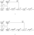
以下、本発明の実施形態を説明する。図1は本発明の実施形態としてのビデオカメラ100の構成を示す図である。なお、本件発明の適用は、撮像手段を有するカメラに限るものではなく、取得した高画素数の画像を画素数の少ない表示手段を有する他の装置、例えばPCや携帯機器にも適用できることは以下の説明から明らかである。
Embodiments of the present invention will be described below. FIG. 1 is a diagram showing a configuration of a
図1において、撮像部101は被写体を撮影して動画データを出力する。本実施形態では、撮像部101は、1フレームが水平1920画素×垂直1080画素で、毎秒60フレームの動画信号を出力する。メモリ102は、撮像部101により得られた動画信号や符号化された動画信号、表示制御部103により処理される画像信号、或いは、動画像に多重して表示するためのオンスクリーンディスプレイ信号(OSD信号)などを記憶する。表示制御部103は、撮影時には撮像部101により得られた動画信号に係る画像を表示部104に表示し、再生時には再生された動画信号に係る画像を表示する。また、表示制御部103は、メニュー画面等の各種のOSD情報を画像に多重して表示部104に表示する。
In FIG. 1, an
表示部104は、液晶ディスプレイやディスプレイドライバを有し、表示制御部103から出力された画像信号に応じて画像を表示する。本実施形態では、表示部104における液晶ディスプレイはデルタ配列の液晶ディスプレイで、その画素数は、水平320画素×垂直240画素である。また、表示部104のディスプレイは、RGBの三種類の色成分に対応した画素を有し、RGBの各画素についてそれぞれ水平方向に320画素を持つ。また、表示部104のディスプレイの各画素のアスペクトを、横1:縦180/240=4:3としている。
The
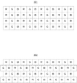
図3に液晶ディスプレイの画素配列の様子を示す。301はストライプ配列を示している。また、302はデルタ配列を示している。302に示す様に、デルタ配列は、1ラインおきに、RGBの各画素が1.5画素ずれて配置される。本実施例は、画素配列がデルタ配列である表示装置に本件発明を適用した例であるが、画素配列がストライプ配列である表示装置であっても、後述のように適宜本件発明を適用することができる。
FIG. 3 shows a pixel arrangement of the liquid crystal display.
また、本実施形態では、表示部104が、ビデオカメラ100の本体に対して回転できるように構成されている。そして、ユーザは、表示部104の向きを撮影者の方に向けるほか、表示部104を回転させて、被写体の方に向けることも可能である。被写体の方に向けた場合、表示部104の上限が逆になるので、画像はその上下の向きが反転されて表示される。
In the present embodiment, the
操作部105は、電源スイッチや撮影開始、停止の指示スイッチ、撮影モードと再生モードを切り替えるためのモードスイッチ、メニュー画面を操作するためのスイッチ等を備える。制御部106はマイクロコンピュータを有し、図示しないメモリに記憶されたプログラムに従ってビデオカメラ100の各部を制御する。制御部106は操作部105からの指示に応じて各部を制御する。また、制御部106は、上記プログラムの制御に従ってOSD情報を生成し、メモリ102に記憶する。
The
記録信号処理部107は、記録時においては撮像部101により得られたフルハイビジョンの動画信号に対して決められた処理を施すと共に、H.264方式等の公知の符号化方式に従って符号化する。また、再生時においては、再生された動画信号を復号する。
The recording
記録再生部108は、記録媒体109に対して動画信号を記録し、また、記録媒体108から動画信号を再生する。記録媒体109は、フラッシュメモリカード等のランダムアクセス可能な記録媒体である。記録媒体109は、不図示の装着、排出機構により、ビデオカメラ100に対して容易に交換可能である。また、記録再生部108は、FATファイルシステム等の公知のファイルシステムに従い、記録媒体109に記録する各種のデータをファイルとして管理する。出力部110は、撮像部101により得られた動画信号や、再生された動画信号をビデオカメラ100の外部の表示装置などに出力する。また、出力部110は、制御部106からの指示に従い、外部出力する動画信号に対し、OSD信号を合成して出力する。データバス111は、各部の間でデータやコマンドを送受信する。
The recording / reproducing
まず、撮影時の動作について説明する。操作部105により電源が投入されると、撮像部101により得られた動画信号はバス111を介してメモリ102に記憶される。表示制御部103は、後述の様にメモリ102に記憶された動画信号を表示部104の画素数にあわせて縮小し、撮影された被写体に係る動画像を表示部104に表示する。
First, the operation during shooting will be described. When the
この様な記録ポーズ状態で、操作部105により記録開始の指示があると、記録信号処理部107は、符号化処理に適した順序でメモリ102に記憶された動画信号を順次読み出す。そして、記録信号処理部107は、H.264/MPEG4−AVC方式に従ってメモリ102から読み出した動画信号を符号化し、再度メモリ102に記憶する。制御部106は各種の制御情報などをメモリ102に記憶し、符号化された動画信号に多重することにより、ストリームデータを生成する。そして、記録再生部108は、メモリ102に所定量のストリームデータが蓄積されたことに応じてメモリ102からデータを読み出し、記録媒体109に記録する。
When a recording start instruction is given by the
これ以降、記録停止の指示があるまでの間、同様の処理を継続する。そして、記録停止の指示があると、記録媒体109に対するデータの記録を停止する。本実施形態では、記録開始の指示から記録停止の指示までの間に記録媒体109に記録された一連のシーンのデータ(クリップ)を一つの動画ファイルとして記録媒体上において管理する。また、記録再生部108は、制御部106の指示により、記録媒体109に記録された動画ファイル等のデータを管理するための管理情報を生成し、この管理情報を記録媒体の所定の領域に記録する。また、記録再生部108は、記録媒体109に記録された管理情報を、動画ファイルを生成、記録するごとに更新する。
Thereafter, the same processing is continued until a recording stop instruction is issued. Then, when there is an instruction to stop recording, data recording to the
次に、再生時の動作を説明する。本実施形態では、記録媒体109に記録された各クリップ(シーン)の代表画像の一覧を示すインデックス画面(後述する)を表示し、これら代表画面から所望のシーンを選択する。制御部106は、操作部105から再生モードへの切り替え指示があると、記録媒体109に記録された各動画ファイルのインデックス画面を表示部104に表示させる。記録再生部108は、インデックス表示の指示があると、記録媒体109に記録された各動画ファイルの先頭部分を読み出し、メモリ102に記憶する。記録信号処理部107はメモリ102に記憶された各動画信号の先頭部分を復号し、その先頭画面をメモリ102に記憶する。表示制御部103は、各動画ファイルの先頭画面を縮小し、メモリ102に記憶する。制御部106はメモリ102に記憶された縮小画面からなるインデックス画面を生成し、表示制御部103に出力する。表示制御部103は、インデックス画面を表示部104に表示する。ユーザは操作部105を操作して、表示部104に表示された代表画像のうち、所望のクリップの代表画像を選択する。
Next, the operation during reproduction will be described. In this embodiment, an index screen (described later) showing a list of representative images of each clip (scene) recorded on the
制御部106は、記録媒体109に記録された管理情報に基づいて記録再生108を制御し、ユーザが選択した代表画像に対応する動画ファイルを記録媒体109から再生する。再生された動画信号は一旦メモリ102に蓄積される。そして、記録信号処理部105はメモリ102から動画信号を読み出して復号し、メモリ102に送る。メモリ102に記憶された動画信号は、出力部110により外部のモニタなどの表示形態に適応した形態に変換されて出力される。また、表示制御部103は、インデックス画面に代えて、メモリ102に記憶された動画信号に係る動画像を表示部104に表示する。
The
次に、表示制御部103について説明する。表示制御部103は、撮影された動画信号、或いは、再生された動画信号の画素数を表示部104における液晶ディスプレイ装置の画素数(サイズ)にあわせて変換する。また、表示制御部103は、表示部104における液晶ディスプレイの画素配列である、デルタ配列に応じて、表示対象となる動画信号の各画素の重心を補正して表示部104に出力する。
Next, the
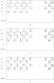
図2(a)は表示制御部103の要部の構成を示す図である。図2(a)において、水平方向変換部201は、撮像部101から出力されて、または記録再生部108で記録媒体109から再生されてメモリ102に記憶された動画信号を読み出し、水平方向の画素数を減少してメモリ102に記憶する。撮像部101から出力された動画信号、或いは、再生された動画信号は、1フレームが水平1920画素×垂直1080画素である。また、撮像部101からの動画信号と再生動画信号は、輝度信号Yと二つの(複数)色差信号Cr,Cbからなる。また、本実施形態では、撮像部101からの動画信号と再生動画信号は、輝度信号Yと色差信号Cr,Cbとの画素の比率が2:1となっている。即ち、各水平ラインの輝度信号Yに対し、Cr,Cbはそれぞれ1画素おきにサブサンプルされた状態で出力され、メモリ102に記憶される。従って、撮像部101からの動画信号或いは再生動画信号における輝度信号Yの水平画素数は1920画素で、色差信号Cr,Cbの水平画素数はそれぞれ960画素となる。
FIG. 2A is a diagram illustrating a configuration of a main part of the
具体的には、水平方向変換部201は帯域制限フィルタとサブサンプル回路を有し、メモリ102に記憶された動画信号を読み出してその周波数帯域を制限する。そして、輝度信号Yと色差信号Cr,Cbそれぞれについて、水平方向の画素数を、表示部104の液晶ディスプレイの水平画素数320画素の2倍である640画素に変換する。
Specifically, the horizontal
本実施形態では、液晶ディスプレイの画素数にあわせて、撮像部101からの元の動画信号の水平画素数1920画素を、その1/6の320画素に変換する。そして、本実施形態では、水平画素数1920画素から直接320画素に変換するのではなく、デルタ配列のディスプレイに適した動画を生成するため、一旦、ディスプレイの水平画素数320画素の2倍の640画素に変換する。このとき、画素間引きのための帯域制限フィルタとしてのLPFのカットオフ周波数を、撮像部101からの動画信号の周波数の1/6から1/3の間に設定する。通常、画素数を1/6に減少する場合、周波数帯域も低域通過フィルタを用いて1/6に制限するが、本実施形態では1/6から1/3の間の帯域に設定する。1/6は入力動画信号の水平画素数に対するディスプレイの水平画素数の比率であり、1/3は入力動画信号の画素数に対するディスプレイの水平画素数の2倍の画素数の比率である。このように、入力画像の水平画素数と表示画素数との比を入力画像の周波数に掛けた周波数よりも高い周波数を帯域制限フィルタの制限周波数帯域として設定している。これにより、ディスプレイに表示される動画の解像感を高くしながら、折り返し雑音を低減することができる。なお、水平方向変換部201における帯域制限フィルタの制限周波数帯域は、制御部106が指示することにより変更することができる。
In this embodiment, according to the number of pixels of the liquid crystal display, the horizontal number of 1920 pixels of the original moving image signal from the
水平変換部201は、このように低域制限を施した後、動画信号の画素をサブサンプルすることにより、水平画素数を640画素に変換する(第1の変換)。ここで、輝度信号Yについては1920画素を3画素ごとに2画素を間引いて640画素に変換する。また、色差信号Cr,Cbについては、入力動画信号の水平画素数960画素を一旦2倍の画素数1920画素に変換した後で帯域制限フィルタにより帯域制限し、その後、3画素ごとに2画素を間引いて640画素に変換する。そして、水平方向変換部201は、画素数を変換した動画信号をメモリ102に記憶する。このように、水平方向変換部201からの動画信号は、水平640画素×垂直1080画素となる。
The
図4に、水平方向変換部201からの動画信号の1フレームの様子を示す。図4(a)は輝度信号Yの様子を示し、図4(b)、(c)はそれぞれ色差信号Cr,Cbの様子を示す。また、図4における各画素の数字は1フレームにおける各画素の位置を示す。図4に示す様に、水平方向変換部201からの動画信号では、互いに同じ位置に輝度信号Yと色差信号Cr,Cbが存在する。
FIG. 4 shows a state of one frame of the moving image signal from the horizontal
次に、垂直方向変換部202は、水平方向変換部201により水平画素数が640画素に変換された動画信号をメモリ102から読み出す。そして、垂直方向変換部202は、読み出した動画信号の水平方向の画素数を、帯域を維持したまま更に1/2に減少した後、垂直方向の画素数をディスプレイの画素数に合わせて240画素に減少して画質調整部203に出力する(第2の変換)。
Next, the vertical
本実施形態では、垂直方向変換部202がメモリ102から読み出した動画信号の水平画素を1/2に変換する際、ディスプレイの画素配列に対応じてサンプリングする画素の位置を決めている。即ち、図5に示す様に、図3のデルタ配列302に対応して、輝度信号Yと色差信号Cr,Cbについて、1ラインごとに水平方向のサンプリング位置をずらしている。図5(a)は輝度信号Yのサンプリング位置を示している。図5(a)より明らかな様に、偶数ライン0、2・・・については2画素目、4画素目、6画素目・・というように1画素おきにサンプリングされる。一方、奇数ライン1、3・・・については1画素目、3画素目、5画素目・・・というように1画素おきにサンプリングされる。このように、サンプリングされる画素の位置が偶数ラインと奇数ラインとで異なっている。図5(b)、(c)も同様に、色差信号Cr,Cbのサンプリング位置を示している。表示部104の画素配列がストライプ配列の場合は、すべてのラインについて同じサンプリング位置を設定すればよい。
In the present embodiment, when the
垂直方向変換部202は、垂直方向の帯域制限フィルタ及び画素補間のための空間フィルタを備えている。そして、垂直方向変換部202は、このようにサンプリングされた動画信号に対して、帯域制限フィルタにより垂直方向に周波数帯域を制限する。1080画素を240画素に変換するため、帯域制限フィルタのカットオフ周波数は元の動画信号の2/9とする。更に、垂直方向変換部202は、空間フィルタにより垂直方向画素数1080画素を240画素に変換するための画素補間を行い、次いで垂直方向に画素を間引くことにより垂直方向画素数1080画素を240画素に変換する。このように変換された動画信号が画質調整部203に出力される。
The vertical
画質調整部203は、制御部106からの指示により垂直方向変換部202からの動画信号に対し、所定の画像処理を施す。例えば、制御部106より画面の一部を明るくする指示があった場合には、指定された位置の画素を指示にあわせて変更する。画質調整部203で処理された動画信号は多重化部204に出力される。なお、実施例のビデオカメラのように、OSD信号の生成、表示機能がない装置に本件発明を適用した場合は、多重化部を入力された画像信号がそのまま出力されるよう設定すればよい。また、OSD信号処理に係わる構成および多重化部を適宜取り除いて本件発明の画像信号を構成しても本件発明の効果が損なわれるものではない。
The image
次に、OSD信号の処理について説明する。制御部106により生成されたOSD信号はメモリ102に記憶される。本実施形態では、OSD信号の1フレームの画素数を、撮像部101からの動画信号の水平、垂直画素数のそれぞれ1/2である水平960画素×水平540画素とする。また、OSD信号は輝度信号Yと色差信号Cr,Cbとから構成される。OSD信号の画素数は、輝度信号Yと色差信号Cr,Cb共に同じであるとする。なお、出力部110により動画信号のOSD信号を合成する場合には、メモリ102に記憶されたOSD信号の画素数を水平、垂直方向にそれぞれ2倍に増加した後に合成する。
Next, OSD signal processing will be described. The OSD signal generated by the
水平方向変換部207は、制御部106からの指示に従ってメモリ102からOSD信号を読み出し、その水平方向の画素数を一旦1920画素に変換する。水平方向変換部207は帯域制限フィルタを有し、1920画素に変換されたOSD信号の周波数帯域を制限し、その後、水平方向の画素数を640画素に変換してメモリ102に記憶する(第3の変換)。
The horizontal
水平方向変換部207における帯域制限フィルタの制限周波数は、水平方向変換部201における帯域制限フィルタの制限周波数と同じとしている。なお、OSD信号の解像感を動画と変えたい場合もあるので、制御部106により、動画信号の場合とは別にOSD信号の制限周波数を設定可能としている。水平方向変換部207により画素数が変換されたOSD信号は、水平640画素×垂直540画素であり、垂直画素数が540画素である以外は、図4の状態と同様である。
The limiting frequency of the band limiting filter in the horizontal
次に、垂直方向変換部208は、水平方向変換部207により水平画素数を640画素に変換されたOSD信号をメモリ102から読み出す。そして、垂直方向変換部208は、読み出したOSD信号の水平方向の画素数を更に1/2に減少した後、垂直方向の画素数をディスプレイの画素数に合わせて240画素に減少して多重化部204に出力する(第4の変換)。
Next, the vertical
垂直方向変換部208は、垂直方向変換部202と同様に、OSD信号の水平画素を1/2に変換する際、ディスプレイの画素配列に応じてサンプリングする画素の位置を決定している。即ち、図5に示す様に、表示部104の画素配列がデルタ配列であることに対応して輝度信号Yと色差信号Cr,Cbについて、1ラインごとに隣接するライン間で水平方向のサンプリング位置をずらしている。なお、表示部104の画素配列がストライプ配列の場合は、動画信号と同様に、すべてのラインについて同じサンプリング位置を適用すればよい。
Similarly to the vertical
また、垂直方向変換部208は、垂直方向の帯域制限フィルタ及び画素補間のための空間フィルタを備えている。そして、垂直方向変換部208は、上述のようにサンプリングされたOSD信号に対して、帯域制限フィルタにより垂直方向に周波数帯域を制限する。垂直画素数540画素を240画素に変換するため、帯域制限フィルタのカットオフ周波数は元の動画信号の4/9とする。更に、垂直方向変換部208は、空間フィルタにより垂直方向画素数540画素を240画素に変換するための画素補間を行い、垂直方向に画素を間引くことにより垂直方向画素数540画素を240画素に変換する。このように変換されたOSD信号が多重化部204に出力される。
The vertical
多重化部204は、制御部106からの指示に従い、画質調整部203からの動画信号と垂直方向変換部208からのOSD信号を多重し、RGB変換部205に出力する。多重化部204は、制御部106から指示された比率に従って、動画信号とOSD信号の各画素に対する合成比率(割合)を設定する。
The
RGB変換部205は、制御部106からの指示に従い、多重化部204から出力された動画信号の輝度信号Yと色差信号Cr,Cbを、R(レッド)、G(グリーン)、B(ブルー)の三種類の色成分信号に変換する。RGB変換部205は、制御部106から出力された変換マトリクスに従い、輝度信号と色差信号をRGB信号に変換する。RGB変換部205は、フレーム内で同じ位置にある輝度信号Yと色差信号Cr,Cbを1画素ずつ用いて、RGB信号を1画素ずつ生成する。即ち、同じ画素位置にある一組の輝度信号Yと色差信号Cr,Cbを、一組のRGB信号に変換する(色変換)。
In accordance with an instruction from the
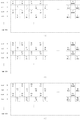
RGB変換部205から出力される動画信号を図6(a)に示す。垂直方向変換部202により水平方向のサンプリング位置がラインごとにずれた状態でサンプリングされているため、一組のRGB画素のサンプリング位置も図6(a)に示す様にライン間でずれている。
The moving image signal output from the
重心補正部206は、RGB変換部205から出力された動画信号におけるRGB各画素の画素重心を表示部104のディスプレイの画素配列に対応した重心となるように補正する。重心補正部206はオーバーサンプリングフィルタを有し、入力された動画信号のRGB各画素に対してフィルタ処理を施すことにより画素重心を補正する。
The center-of-
図6(a)に示す様に、水平方向のサンプリング位置をライン間でずらした結果、RGB変換部205から出力された動画信号におけるGの画素位置が図3の302に示すデルタ配列におけるGの位置に対応している。これは、輝度成分を主成分とする色がGであるため、垂直方向変換部202におけるサンプリング処理でGの位置を最も意識しているためである。このように、Gの重心は既にデルタ配列に合わせてあるため、重心補正部206によりRとBの重心をGの重心を中心として補正する。具体的には、図6(b)に示すとおり、偶数ラインでは、Gを中心とすると、両隣のRとBは3分の1画素重心がずれていることになる。また、奇数ラインでは、一組のRBG画素が、画面左からGBRの順に配置されるので、Gに対し、Bの重心が1/3ずれ、Rの重心が2/3ずれている。
As shown in FIG. 6A, as a result of shifting the sampling position in the horizontal direction between the lines, the G pixel position in the moving image signal output from the
図7(a)は、重心補正部206におけるオーバーサンプリングフィルタを示している。また、図7(b)は、図7(a)のオーバーサンプリングフィルタの周波数特性を示している。図7(b)の各画素が図7(a)のフィルタにおける各タップから出力される画素位置に対応し、また、各画素の記号がタップ係数に対応している。図7(b)のフィルタの特性はGを中心として、RとBの重心をデルタ配列に合わせてずらすための特性である。フィルタの総タップ数は23タップ、Rは8個、Gは7個、Bは8個のフィルタ演算係数を有する。
FIG. 7A shows an oversampling filter in the
RGB変換部205からのRGB各画素の動画信号がラインごとに順次フィルタに入力される。遅延部701aから701gはそれぞれ、入力されたRGB各画素の動画信号を3画素分順次遅延させて出力する。従って、フィルタに入力された画素がGの画素の場合、各タップからはGの画素が出力される。同様に、入力された画素がB,Rのときは、各タップからそれぞれB,Rの画素が出力される。乗算器702aから702hは、制御部106からの指示に従って係数を選択し、選択した係数と各タップからの信号とを乗算する。本実施形態では、フィルタに入力された画素がGの場合、各乗算器702aから702gが係数G1からG7をそれぞれ選択するように制御する。また、フィルタに入力された画素がB,Rの場合、各乗算器702aから702hがそれぞれ係数B1からB8、或いはR1からR8をそれぞれ選択するように制御する。
The moving image signal of each RGB pixel from the
加算器703は各乗算器からの出力を加算し、重心が補正されたRGB信号の動画信号として出力する。このように重心補正部206からの重心補正されたRGBの動画信号が表示部104に出力される。
An
なお、表示部104の画素配列がストライプ配列である場合は、垂直方向変換部と同様に、表示部の画素配列に対応して重心補正の設定を適宜変更すればよい(例えばフィルタ係数の設定変更)。
When the pixel arrangement of the
なお、本実施形態では、輝度信号と色差信号とからなるOSD信号を生成したが、RGB信号からなるOSD信号を生成するようにしてもよい。RGB信号からなるOSD信号を生成した場合の表示制御部103の構成を図2(b)に示す。この場合、OSD信号として、水平960画素×垂直540画素のRGB信号からなるOSD信号を生成する。また、OSD信号は、RGBの各色成分について、それぞれ水平画素数が960画素であるとする。
In the present embodiment, an OSD signal composed of a luminance signal and a color difference signal is generated. However, an OSD signal composed of an RGB signal may be generated. FIG. 2B shows the configuration of the
図2(b)の水平方向変換部207は、RGB信号からなるOSD信号をメモリ207から読み出し、RGBの各色成分信号について、水平方向の画素数を640画素に変換する。この際、図2(a)での輝度信号と色差信号の場合と同様に、一旦1920画素に変換した後、帯域制限を施して640画素に変換する。そして、垂直方向変換部208は、メモリ102より水平画素数が640画素のRGB信号を読み出し、水平方向の画素数をディスプレイの水平画素数に合わせて320画素に変換する。このとき、輝度信号と色差信号の場合と同様に、ライン間でサンプリング位置をずらす。そして、サンプリングされたRGB信号に対し、垂直方向に帯域制限を施した後、垂直方向の画素数をディスプレイの画素数にあわせて240画素に変換して多重化部205に出力する。垂直方向変換部208から出力されるRGB信号の画素位置は、図6(a)に示す状態となっている。
The horizontal
これ以降は前述と同様に、多重化部204によりOSD信号と動画信号を多重し、重心補正部206により各画素の重心を補正して出力する。
Thereafter, as described above, the
次に、表示部104を回転させて、表示する画像を反転する場合の処理について説明する。表示部104を回転させて被写体の方に向けた場合、本実施形態では、表示部104に表示する画像の向きを上下方向に反転して表示する。反転表示の場合には、通常表示の状態において最も下のラインに動画の最も上のラインが表示されることになる。本実施形態では、ディスプレイの垂直画素数が240画素のため、通常表示の状態においてディスプレイの最も下のラインは図5の場合、水平方向の奇数ライン(239)となる。反転表示の状態では、このラインが最初(偶数ライン)に表示されるため、図5のサンプリング位置は図3のデルタ配列に対応しなくなる。そのため、垂直方向変換部202においてサンプリングする画素の位置を通常表示のときとは異なる設定にする。
Next, processing when the
図2(a)において、水平方向変換部201は前述の様にメモリ102より動画信号を読み出し、水平方向の画素数を640画素に変換してメモリ102に記憶する。垂直方向変換部202は、メモリ102から動画信号を読み出し、水平方向の画素数をディスプレイの画素数にあわせて320画素に変換する。このとき、垂直方向変換部202は、制御部106からの反転表示の指示に応じて、通常の表示の場合とは異なる画素位置をサンプリングする。反転表示の際にサンプリングされる画素位置を図8に示す。図8(a)から(c)はそれぞれ、輝度信号Yと色差信号Cr,Cbのサンプリング位置を示している。図8に示す様に、各ラインにおいて、図5に示した通常の表示の際のサンプリング位置とは異なる位置をサンプリングしている。
2A, the horizontal
そして、垂直方向変換部202は、動画信号の垂直方向の画素数をディスプレイの画素数にあわせて240画素に変換し、画質調整部203に出力する。画質調整部203は前記の様に動画信号を処理して多重化部204に出力する。
Then, the vertical
一方、OSD信号についても、通常の表示の場合と同様に水平方向変換部207により水平方向の画素数を640画素に変換する。そして、垂直方向変換部208により、図8に示す様に、各ラインについて、通常の表示の場合とは異なる位置をサンプリングして水平方向の画素数を320画素に変換した後、垂直方向の画素数を240画素に変換して多重化部204に出力する。
On the other hand, for the OSD signal, the horizontal
多重化部204は動画信号とOSD信号を多重し、RGB変換部205に出力する。RGB変換部205は、前述の様に、多重化部204から出力された動画信号の輝度信号Yと色差信号Cr,CbをRGBの色成分信号に変換する。RGB変換部205から出力されるRGB信号を図9(a)に示す。
The
RGB変換部205から出力された動画信号は重心補正部206に出力される。重心補正部206は、RGB変換部205から出力された動画信号におけるRGB各画素の画素重心を表示部104のディスプレイの画素配列に対応した重心となるように補正する。また、重心補正部206は、制御部106より反転表示の指示があると、表示部104を回転した状態での画素配列に応じて重心を適宜補正する。
The moving image signal output from the
図9(b)は、反転表示の際の各画素の重心を示している。重心補正部206は、反転表示の場合、図9(b)に示した重心となるように、フィルタの係数を設定する。重心補正部206により画素重心が反転表示に応じて変更されたRGB信号からなる動画信号は表示部104に出力される。
FIG. 9B shows the center of gravity of each pixel in the reverse display. The center-of-
表示部104は、制御部106より反転表示の指示があると、表示制御部103より出力された動画信号の各ラインを、通常表示の場合とは逆に、画像の最も下のラインから順次表示する。
When the
このように本実施形態では、水平n画素×垂直m画素の(n、mはそれぞれ所定の自然数)デルタ配列のディスプレイに対して画素数が多い動画信号を表示する構成を開示している。すなわち、輝度信号と色差信号からなる動画信号の水平画素数を、一旦ディスプレイの表示画素数nの2倍の2n画素に変換する。そして、ライン間でサンプリング位置をずらしながら、水平方向の画素数をディスプレイの水平画素数に合わせてn画素に変換するとともに垂直方向をm画素に変換する。その後、輝度信号と色差信号とを、RGBの色成分信号に変換し、更に、画素重心をディスプレイの画素配列に対応じて補正している。 As described above, the present embodiment discloses a configuration in which a moving image signal having a large number of pixels is displayed on a display having a delta arrangement of horizontal n pixels × vertical m pixels (n and m are predetermined natural numbers, respectively). That is, the horizontal pixel number of the moving image signal composed of the luminance signal and the color difference signal is once converted to 2n pixels, which is twice the display pixel number n of the display. Then, while shifting the sampling position between lines, the number of pixels in the horizontal direction is converted to n pixels in accordance with the number of horizontal pixels of the display, and the vertical direction is converted to m pixels. Thereafter, the luminance signal and the color difference signal are converted into RGB color component signals, and the pixel centroid is corrected in accordance with the pixel arrangement of the display.
反転表示の場合においても、表示部104の画素配列のタイプに対応して、垂直方向変換部での水平画素のサンプリング位置および重心補正の構成を適宜設定すればよい。
Also in the case of reverse display, the horizontal pixel sampling position and the center-of-gravity correction configuration in the vertical direction conversion unit may be set as appropriate in accordance with the pixel arrangement type of the
上述したように、本件発明によれば、高精度な補間フィルタなどを用いずに、ディスプレイの画素配列に対応した高精細な画像を出力できる画像信号処理装置を提供できる。 As described above, according to the present invention, it is possible to provide an image signal processing apparatus that can output a high-definition image corresponding to the pixel arrangement of the display without using a high-precision interpolation filter or the like.
なお、本実施形態では、動画を撮影するビデオカメラにおいて動画像を表示する場合について説明したが、静止画像などの画像信号を表示する場合にも本発明を同様に適用可能である。また、撮像手段を有しない装置において、記録媒体、通信等を介して提供(取得)される高精細画像を画素数の少ない表示部に表示する場合にも適用可能である。この場合は、提供された高精細画像(例えば動画ファイル)をメモリ102に記憶すればよい。
In the present embodiment, the case where a moving image is displayed in a video camera that shoots a moving image has been described. However, the present invention is also applicable to the case where an image signal such as a still image is displayed. Further, the present invention can be applied to a case where a high-definition image provided (acquired) via a recording medium, communication, or the like is displayed on a display unit with a small number of pixels in an apparatus that does not include an imaging unit. In this case, the provided high-definition image (for example, a moving image file) may be stored in the
また、本発明の目的は次の構成によっても達成されることは言うまでもない。すなわち、前述した実施形態の機能を実現するソフトウェアのプログラムコードを記録した記憶媒体をシステム或いは装置に供給する構成である。この場合、そのシステム或いは装置のコンピュータ(またはCPUやMPU)が記憶媒体に格納されたプログラムコードを読み出し実行することによって本件発明が達成される。 Needless to say, the object of the present invention can also be achieved by the following configuration. That is, the storage medium storing the program code of software that realizes the functions of the above-described embodiments is supplied to the system or apparatus. In this case, the present invention is achieved by the computer (or CPU or MPU) of the system or apparatus reading and executing the program code stored in the storage medium.
この場合、記憶媒体から読み出されたプログラムコード自体が前述した実施形態の機能を実現することになり、プログラムコード自体及びそのプログラムコードを記憶した記憶媒体は本発明を構成することになる。 In this case, the program code itself read from the storage medium realizes the functions of the above-described embodiments, and the program code itself and the storage medium storing the program code constitute the present invention.
プログラムコードを供給するための記憶媒体としては、例えば、フレキシブルディスク、ハードディスク、光ディスク、光磁気ディスク、CD−ROM、CD−R、磁気テープ、不揮発性のメモリカード、ROM等を用いることができる。 As a storage medium for supplying the program code, for example, a flexible disk, a hard disk, an optical disk, a magneto-optical disk, a CD-ROM, a CD-R, a magnetic tape, a nonvolatile memory card, a ROM, or the like can be used.
また、コンピュータが読み出したプログラムコードを実行することにより、前述した実施形態の機能が実現されるだけでなく、次のような場合も本件発明に含まれることは言うまでもない。すなわち、そのプログラムコードの指示に基づき、コンピュータ上で稼動しているOS(基本システム或いはオペレーティングシステム)などが実際の処理の一部又は全部を行い、その処理によって前述した実施形態の機能が実現される場合である。 In addition, by executing the program code read by the computer, not only the functions of the above-described embodiments are realized, but the following cases are also included in the present invention. That is, based on the instruction of the program code, an OS (basic system or operating system) running on the computer performs part or all of the actual processing, and the functions of the above-described embodiments are realized by the processing. This is the case.
さらに、記憶媒体から読み出されたプログラムコードが、コンピュータに挿入された機能拡張ボードやコンピュータに接続された機能拡張ユニットに備わるメモリに書込まれた場合も本件発明に含まれる。すなわち、メモリに書き込まれたプログラムコードの指示に基づき、その機能拡張ボードや機能拡張ユニットに備わるCPU等が実際の処理の一部又は全部を行い、その処理によって前述した実施形態の機能が実現される場合である。 Further, the present invention includes a case where the program code read from the storage medium is written in a memory provided in a function expansion board inserted into the computer or a function expansion unit connected to the computer. That is, the CPU of the function expansion board or function expansion unit performs part or all of the actual processing based on the instruction of the program code written in the memory, and the functions of the above-described embodiments are realized by the processing. This is the case.
以上、本発明を好ましい実施例により説明したが、本発明は上述した実施例に限ることなくクレームに示した範囲で種々の変更が可能である。 Although the present invention has been described with reference to the preferred embodiments, the present invention is not limited to the above-described embodiments, and various modifications can be made within the scope shown in the claims.
Claims (6)
輝度信号と色差信号とを含む画像信号を入力する入力手段と、
メモリと、
前記入力手段により入力された画像信号の水平方向の画素数を2n画素に変換し、前記画素数が変換された画像信号を前記メモリに記憶する第1の変換手段と、
前記第1の変換手段により前記メモリに記憶された画像信号を読み出し、前記読み出した画像信号の画素を前記表示装置の画素配列に応じてサンプリングすることにより前記読み出した画像信号の水平方向の画素数をn画素に変換すると共に、前記読み出した画像信号の垂直方向の画素数をm画素に変換する第2の変換手段と、
前記第2の変換手段から出力された画像信号を、前記表示装置の画素に対応したレッド、グリーン、ブルーの色成分信号に変換する色変換手段と、
前記色変換手段から出力された色成分信号を前記表示装置の画素配列に応じて重心補正し、前記重心補正された色成分信号を前記表示装置に出力する補正手段とを備え、
前記第2の変換手段は、前記色変換手段から出力された色成分信号におけるグリーンの画素位置が前記表示装置における偶数ラインと奇数ラインそれぞれのグリーンの画素位置に対応するように、サンプリングする画素の位置を隣接するライン間で異ならせ、
前記補正手段は、前記色変換手段から出力された色成分信号における、レッド及びブルーの色成分信号の重心を、前記表示装置におけるそれぞれの色成分信号の画素位置に応じて補正することを特徴とする画像信号処理装置。 An image signal processing device that outputs an image signal to a display device having a horizontal delta pixel × vertical m pixel (n and m are natural numbers, respectively) and a pixel arrangement of which is a delta arrangement ,
An input means for inputting an image signal including a luminance signal and a color difference signal;
Memory,
First conversion means for converting the number of pixels in the horizontal direction of the image signal input by the input means to 2n pixels, and storing the image signal in which the number of pixels is converted in the memory;
The number of pixels in the horizontal direction of the read image signal by reading the image signal stored in the memory by the first conversion unit and sampling the pixels of the read image signal according to the pixel arrangement of the display device Second conversion means for converting the number of pixels in the vertical direction of the read image signal into m pixels,
Color conversion means for converting the image signal outputted from said second converting means, red corresponding to a pixel of the display device, green, and blue color component signals,
E Bei and correction means for outputting a color component signal output from the color converting unit and centroid corrected according to the pixel arrangement of said display device, the center of gravity corrected color component signals to said display device,
The second conversion unit is configured to select a pixel to be sampled so that a green pixel position in the color component signal output from the color conversion unit corresponds to a green pixel position in each of the even line and the odd line in the display device. Make the position different between adjacent lines,
The correction unit corrects the center of gravity of the red and blue color component signals in the color component signal output from the color conversion unit according to the pixel position of each color component signal in the display device. An image signal processing device.
前記出力手段から出力されたオンスクリーンディスプレイ信号と前記第2の変換手段から出力された画像信号とを多重する多重手段とを備え、
前記出力手段から出力されるオンスクリーンディスプレイ信号は輝度信号と色差信号からなり、前記出力手段から出力されるオンスクリーンディスプレイ信号の水平方向および垂直方向の画素数と画素位置は、前記第2の変換手段から出力される画像信号の水平方向および垂直方向の画素数及び画素位置とそれぞれ同じであることを特徴とする請求項1に記載の画像信号処理装置。 Output means for outputting an on-screen display signal for multiplexing and displaying the input image signal;
A multiplexing unit that multiplexes the on-screen display signal output from the output unit and the image signal output from the second conversion unit;
The on-screen display signal output from the output means includes a luminance signal and a color difference signal, and the number of pixels and the pixel position in the horizontal direction and the vertical direction of the on-screen display signal output from the output means are the second conversion. 2. The image signal processing apparatus according to claim 1, wherein the number of pixels and the pixel position in the horizontal direction and the vertical direction of the image signal output from the means are the same.
前記第4の変換手段はオンスクリーンディスプレイ信号を前記多重手段に出力することを特徴とする請求項2に記載の画像信号処理装置。 The output means is a means for inputting an on-screen display signal; converts the number of pixels in the horizontal direction of the input on-screen display signal to 2n pixels; and the on-screen display signal having the converted number of pixels is stored in the memory. Third storage means for storing, and the on-screen display signal stored in the memory by the third conversion means is read, and the pixels of the read on-screen display signal are sampled corresponding to the pixel arrangement of the display device A fourth conversion means for converting the number of pixels in the horizontal direction of the read on-screen display signal into n pixels and converting the number of pixels in the vertical direction of the read-out on-screen display signal into m pixels. Have
The image signal processing apparatus according to claim 2, wherein the fourth conversion unit outputs an on-screen display signal to the multiplexing unit.
前記撮像手段により得られた画像信号を記録媒体に記録し、前記記録媒体から画像信号を再生する記録再生手段とを備え、
前記入力手段は、前記撮像手段により得られた画像信号および前記記録再生手段により記録媒体から再生された画像信号のいずれかを入力することを特徴とする請求項1から4の何れか1項に記載の画像信号処理装置。 Imaging means;
Recording and reproducing means for recording an image signal obtained by the imaging means on a recording medium and reproducing the image signal from the recording medium;
5. The input device according to claim 1, wherein the input unit inputs one of an image signal obtained by the imaging unit and an image signal reproduced from a recording medium by the recording / reproducing unit. The image signal processing apparatus described.
輝度信号と色差信号とを含む画像信号を入力する入力ステップと、
前記入力ステップで入力した画像信号の水平方向の画素数を2n画素に変換し、前記画素数が変換された画像信号をメモリに記憶する第1の変換ステップと、
前記第1の変換ステップで前記メモリに記憶した画像信号を読み出し、前記読み出した画像信号の画素を前記表示装置の所定の画素配列に応じてサンプリングすることにより前記読み出した画像信号の水平方向の画素数をn画素に変換すると共に、前記読み出した画像信号の垂直方向の画素数をm画素に変換する第2の変換ステップと、
前記第2の変換ステップで得られた画像信号を、前記表示装置の画素に対応したレッド、グリーン、ブルーの色成分信号に変換する色変換ステップと、
前記色変換ステップで得られた色成分信号を前記表示装置の画素配列に応じて重心補正し、前記重心補正された色成分信号を前記表示装置に出力する補正ステップとを備え、
前記第2の変換ステップは、前記色変換手段から出力された色成分信号におけるグリーンの画素位置が前記表示装置における偶数ラインと奇数ラインそれぞれのグリーンの画素位置に対応するように、サンプリングする画素の位置を隣接するライン間で異ならせ、
前記補正ステップは、前記色変換ステップで出力された色成分信号における、レッド及びブルーの色成分信号の重心を、前記表示装置におけるそれぞれの色成分信号の画素位置に応じて補正することを特徴とする画像信号処理方法。 An image signal processing method for outputting an image signal to a display device comprising a horizontal n pixels × vertical m pixels (n and m are natural numbers, respectively) and a pixel arrangement of a delta arrangement ,
An input step for inputting an image signal including a luminance signal and a color difference signal;
A first conversion step of converting the number of pixels in the horizontal direction of the image signal input in the input step into 2n pixels, and storing the image signal in which the number of pixels is converted in a memory;
Pixels in the horizontal direction of the read image signal are read by reading the image signal stored in the memory in the first conversion step and sampling the pixels of the read image signal according to a predetermined pixel arrangement of the display device A second conversion step of converting the number of pixels into n pixels and converting the number of pixels in the vertical direction of the read image signal into m pixels;
A color conversion step of converting an image signal obtained by the second conversion step, red corresponding to a pixel of the display device, green, and blue color component signals,
E Bei a correction step of outputting color component signals obtained by the color conversion step to the center of gravity corrected in accordance with the picture element array of the display device, the center of gravity corrected color component signals to said display device,
In the second conversion step, the pixel to be sampled is adjusted so that the green pixel position in the color component signal output from the color conversion unit corresponds to the green pixel position in each of the even-numbered line and the odd-numbered line in the display device. Make the position different between adjacent lines,
In the correction step, the center of gravity of the red and blue color component signals in the color component signal output in the color conversion step is corrected according to the pixel position of each color component signal in the display device. image signal processing method of.
Priority Applications (2)
| Application Number | Priority Date | Filing Date | Title |
|---|---|---|---|
| JP2010273567A JP5658548B2 (en) | 2010-12-08 | 2010-12-08 | Image signal processing apparatus, image signal processing method, and program |
| US13/306,479 US8744233B2 (en) | 2010-12-08 | 2011-11-29 | Image signal processing apparatus, image signal processing method, and program |
Applications Claiming Priority (1)
| Application Number | Priority Date | Filing Date | Title |
|---|---|---|---|
| JP2010273567A JP5658548B2 (en) | 2010-12-08 | 2010-12-08 | Image signal processing apparatus, image signal processing method, and program |
Publications (3)
| Publication Number | Publication Date |
|---|---|
| JP2012123175A JP2012123175A (en) | 2012-06-28 |
| JP2012123175A5 JP2012123175A5 (en) | 2014-01-30 |
| JP5658548B2 true JP5658548B2 (en) | 2015-01-28 |
Family
ID=46199476
Family Applications (1)
| Application Number | Title | Priority Date | Filing Date |
|---|---|---|---|
| JP2010273567A Expired - Fee Related JP5658548B2 (en) | 2010-12-08 | 2010-12-08 | Image signal processing apparatus, image signal processing method, and program |
Country Status (2)
| Country | Link |
|---|---|
| US (1) | US8744233B2 (en) |
| JP (1) | JP5658548B2 (en) |
Families Citing this family (9)
| Publication number | Priority date | Publication date | Assignee | Title |
|---|---|---|---|---|
| CN105027191B (en) * | 2013-09-12 | 2017-11-17 | 深圳云英谷科技有限公司 | The method and apparatus rendered for sub-pixel |
| KR102459917B1 (en) * | 2015-02-23 | 2022-10-27 | 삼성전자주식회사 | Image signal processor and devices having the same |
| CN104933980B (en) * | 2015-06-30 | 2017-10-31 | 京东方科技集团股份有限公司 | A kind of display drive method, device and display device |
| US11308848B2 (en) | 2020-08-05 | 2022-04-19 | Jade Bird Display (shanghai) Limited | Scan needle and scan display system including same |
| US11317065B2 (en) * | 2020-08-05 | 2022-04-26 | Jade Bird Display (shanghai) Limited | Scan needle and scan display system including same |
| US11270632B2 (en) | 2020-08-05 | 2022-03-08 | Jade Bird Display (shanghai) Limited | Scan needle and scan display system including same |
| US11270620B2 (en) | 2020-08-05 | 2022-03-08 | Jade Bird Display (shanghai) Limited | Scan needle and scan display system including same |
| US11308862B2 (en) | 2020-08-05 | 2022-04-19 | Jade Bird Display (shanghai) Limited | Scan needle and scan display system including same |
| US11527572B2 (en) | 2020-08-05 | 2022-12-13 | Jade Bird Display (shanghai) Limited | Scan needle and scan display system including same |
Family Cites Families (8)
| Publication number | Priority date | Publication date | Assignee | Title |
|---|---|---|---|---|
| JPH10105143A (en) * | 1996-09-30 | 1998-04-24 | Toshiba Corp | Image display device |
| JPH10187089A (en) * | 1996-12-26 | 1998-07-14 | Canon Inc | Device and method for display control |
| JP2000293145A (en) * | 1999-04-06 | 2000-10-20 | Canon Inc | Picture display device and its method |
| US20060012714A1 (en) * | 2004-07-16 | 2006-01-19 | Greenforest Consulting, Inc | Dual-scaler architecture for reducing video processing requirements |
| JP2007096472A (en) | 2005-09-27 | 2007-04-12 | Canon Inc | Image display device |
| JP5424534B2 (en) * | 2007-01-31 | 2014-02-26 | 日立コンシューマエレクトロニクス株式会社 | Image processing apparatus and image display apparatus |
| JP4450014B2 (en) * | 2007-05-30 | 2010-04-14 | セイコーエプソン株式会社 | Projector, image display device, and image processing device |
| JP2011097541A (en) * | 2009-11-02 | 2011-05-12 | Sony Corp | Solid-state imaging element, camera system, method of reading solid imaging element, and program |
-
2010
- 2010-12-08 JP JP2010273567A patent/JP5658548B2/en not_active Expired - Fee Related
-
2011
- 2011-11-29 US US13/306,479 patent/US8744233B2/en not_active Expired - Fee Related
Also Published As
| Publication number | Publication date |
|---|---|
| JP2012123175A (en) | 2012-06-28 |
| US20120148209A1 (en) | 2012-06-14 |
| US8744233B2 (en) | 2014-06-03 |
Similar Documents
| Publication | Publication Date | Title |
|---|---|---|
| JP5658548B2 (en) | Image signal processing apparatus, image signal processing method, and program | |
| JP5036410B2 (en) | Imaging apparatus and control method thereof | |
| US7586522B2 (en) | Image processing device | |
| KR100957261B1 (en) | Image pickup device and chromatic aberration correction method | |
| JP4596986B2 (en) | Imaging device | |
| US8368775B2 (en) | Imaging apparatus and live-view image display method thereof | |
| US7466451B2 (en) | Method and apparatus for converting motion image data, and method and apparatus for reproducing motion image data | |
| US7787023B2 (en) | Video signal processing apparatus | |
| JP2007336515A (en) | Camera, image output apparatus, image output method, image recording method, program and recording medium | |
| JP2007221181A (en) | Imaging apparatus | |
| JP2008124671A (en) | Imaging apparatus and imaging method | |
| US20060232688A1 (en) | Image processing system, image pickup apparatus, image pickup method, image reproducing apparatus, and image reproducing method | |
| JP4596987B2 (en) | Imaging device | |
| JP6351212B2 (en) | IMAGING DEVICE, IMAGING DEVICE CONTROL METHOD AND SYSTEM | |
| JP5938655B2 (en) | Playback device, imaging device, and program | |
| JP5866826B2 (en) | Imaging device | |
| US7389004B2 (en) | Image processing apparatus | |
| JP6351213B2 (en) | IMAGING DEVICE, IMAGING DEVICE CONTROL METHOD AND SYSTEM | |
| JP4387264B2 (en) | Imaging apparatus and image generation method thereof | |
| JP4379334B2 (en) | Image composition apparatus and electronic camera | |
| JP2001024975A (en) | Image pickup device | |
| JP4586044B2 (en) | Image recording apparatus, control method therefor, and imaging apparatus | |
| JP2017032879A (en) | Liquid crystal display device | |
| JP2006134030A (en) | Image processor | |
| JP2015106820A (en) | Imaging device, image processing method, and image processing program |
Legal Events
| Date | Code | Title | Description |
|---|---|---|---|
| RD05 | Notification of revocation of power of attorney |
Free format text: JAPANESE INTERMEDIATE CODE: A7425 Effective date: 20120730 |
|
| RD05 | Notification of revocation of power of attorney |
Free format text: JAPANESE INTERMEDIATE CODE: A7425 Effective date: 20120731 |
|
| RD03 | Notification of appointment of power of attorney |
Free format text: JAPANESE INTERMEDIATE CODE: A7423 Effective date: 20120831 |
|
| RD05 | Notification of revocation of power of attorney |
Free format text: JAPANESE INTERMEDIATE CODE: A7425 Effective date: 20130701 |
|
| A521 | Request for written amendment filed |
Free format text: JAPANESE INTERMEDIATE CODE: A523 Effective date: 20131206 |
|
| A621 | Written request for application examination |
Free format text: JAPANESE INTERMEDIATE CODE: A621 Effective date: 20131206 |
|
| A977 | Report on retrieval |
Free format text: JAPANESE INTERMEDIATE CODE: A971007 Effective date: 20140625 |
|
| A131 | Notification of reasons for refusal |
Free format text: JAPANESE INTERMEDIATE CODE: A131 Effective date: 20140708 |
|
| A521 | Request for written amendment filed |
Free format text: JAPANESE INTERMEDIATE CODE: A523 Effective date: 20140903 |
|
| TRDD | Decision of grant or rejection written | ||
| A01 | Written decision to grant a patent or to grant a registration (utility model) |
Free format text: JAPANESE INTERMEDIATE CODE: A01 Effective date: 20141030 |
|
| A61 | First payment of annual fees (during grant procedure) |
Free format text: JAPANESE INTERMEDIATE CODE: A61 Effective date: 20141128 |
|
| R151 | Written notification of patent or utility model registration |
Ref document number: 5658548 Country of ref document: JP Free format text: JAPANESE INTERMEDIATE CODE: R151 |
|
| LAPS | Cancellation because of no payment of annual fees |