JP5657740B2 - Method and apparatus for dispensing diagnostic test strips - Google Patents
Method and apparatus for dispensing diagnostic test strips Download PDFInfo
- Publication number
- JP5657740B2 JP5657740B2 JP2013097687A JP2013097687A JP5657740B2 JP 5657740 B2 JP5657740 B2 JP 5657740B2 JP 2013097687 A JP2013097687 A JP 2013097687A JP 2013097687 A JP2013097687 A JP 2013097687A JP 5657740 B2 JP5657740 B2 JP 5657740B2
- Authority
- JP
- Japan
- Prior art keywords
- test strip
- test strips
- test
- lid
- stack
- Prior art date
- Legal status (The legal status is an assumption and is not a legal conclusion. Google has not performed a legal analysis and makes no representation as to the accuracy of the status listed.)
- Active
Links
Images


Classifications
-
- G—PHYSICS
- G01—MEASURING; TESTING
- G01N—INVESTIGATING OR ANALYSING MATERIALS BY DETERMINING THEIR CHEMICAL OR PHYSICAL PROPERTIES
- G01N33/00—Investigating or analysing materials by specific methods not covered by groups G01N1/00 - G01N31/00
- G01N33/48—Biological material, e.g. blood, urine; Haemocytometers
- G01N33/483—Physical analysis of biological material
- G01N33/487—Physical analysis of biological material of liquid biological material
- G01N33/4875—Details of handling test elements, e.g. dispensing or storage, not specific to a particular test method
- G01N33/48757—Test elements dispensed from a stack
-
- B—PERFORMING OPERATIONS; TRANSPORTING
- B65—CONVEYING; PACKING; STORING; HANDLING THIN OR FILAMENTARY MATERIAL
- B65D—CONTAINERS FOR STORAGE OR TRANSPORT OF ARTICLES OR MATERIALS, e.g. BAGS, BARRELS, BOTTLES, BOXES, CANS, CARTONS, CRATES, DRUMS, JARS, TANKS, HOPPERS, FORWARDING CONTAINERS; ACCESSORIES, CLOSURES, OR FITTINGS THEREFOR; PACKAGING ELEMENTS; PACKAGES
- B65D83/00—Containers or packages with special means for dispensing contents
- B65D83/08—Containers or packages with special means for dispensing contents for dispensing thin flat articles in succession
- B65D83/0805—Containers or packages with special means for dispensing contents for dispensing thin flat articles in succession through an aperture in a wall
- B65D83/0811—Containers or packages with special means for dispensing contents for dispensing thin flat articles in succession through an aperture in a wall with means for assisting dispensing
- B65D83/0823—Containers or packages with special means for dispensing contents for dispensing thin flat articles in succession through an aperture in a wall with means for assisting dispensing the articles being pushed and slid through the aperture
- B65D83/0829—Containers or packages with special means for dispensing contents for dispensing thin flat articles in succession through an aperture in a wall with means for assisting dispensing the articles being pushed and slid through the aperture by means of an actuator
-
- B—PERFORMING OPERATIONS; TRANSPORTING
- B65—CONVEYING; PACKING; STORING; HANDLING THIN OR FILAMENTARY MATERIAL
- B65D—CONTAINERS FOR STORAGE OR TRANSPORT OF ARTICLES OR MATERIALS, e.g. BAGS, BARRELS, BOTTLES, BOXES, CANS, CARTONS, CRATES, DRUMS, JARS, TANKS, HOPPERS, FORWARDING CONTAINERS; ACCESSORIES, CLOSURES, OR FITTINGS THEREFOR; PACKAGING ELEMENTS; PACKAGES
- B65D83/00—Containers or packages with special means for dispensing contents
- B65D83/08—Containers or packages with special means for dispensing contents for dispensing thin flat articles in succession
- B65D83/0847—Containers or packages with special means for dispensing contents for dispensing thin flat articles in succession through an aperture at the junction of two walls
- B65D83/0852—Containers or packages with special means for dispensing contents for dispensing thin flat articles in succession through an aperture at the junction of two walls with means for assisting dispensing
- B65D83/0864—Containers or packages with special means for dispensing contents for dispensing thin flat articles in succession through an aperture at the junction of two walls with means for assisting dispensing the articles being pushed and slid through the aperture
- B65D83/087—Containers or packages with special means for dispensing contents for dispensing thin flat articles in succession through an aperture at the junction of two walls with means for assisting dispensing the articles being pushed and slid through the aperture by means of an actuator
-
- B—PERFORMING OPERATIONS; TRANSPORTING
- B65—CONVEYING; PACKING; STORING; HANDLING THIN OR FILAMENTARY MATERIAL
- B65H—HANDLING THIN OR FILAMENTARY MATERIAL, e.g. SHEETS, WEBS, CABLES
- B65H3/00—Separating articles from piles
- B65H3/24—Separating articles from piles by pushers engaging the edges of the articles
-
- G—PHYSICS
- G01—MEASURING; TESTING
- G01N—INVESTIGATING OR ANALYSING MATERIALS BY DETERMINING THEIR CHEMICAL OR PHYSICAL PROPERTIES
- G01N33/00—Investigating or analysing materials by specific methods not covered by groups G01N1/00 - G01N31/00
- G01N33/48—Biological material, e.g. blood, urine; Haemocytometers
- G01N33/483—Physical analysis of biological material
- G01N33/487—Physical analysis of biological material of liquid biological material
- G01N33/4875—Details of handling test elements, e.g. dispensing or storage, not specific to a particular test method
Abstract
Description
本発明は、全体的に、生物学流体を試験するための診断試験ストリップに関する。より詳細には、本発明は、診断試験ストリップを格納しかつ分与するための装置および方法に関する。 The present invention relates generally to diagnostic test strips for testing biological fluids. More particularly, the present invention relates to an apparatus and method for storing and dispensing diagnostic test strips.
診断試験ストリップは、生物学流体内の検体濃度を測定するために使用される。例えば、診断試験ストリップは、血液グルコースレベルを監視するために糖尿病患者によってしばしば使用される。 The diagnostic test strip is used to measure the analyte concentration in the biological fluid. For example, diagnostic test strips are often used by diabetic patients to monitor blood glucose levels.
それらの完全性を保存するために、診断試験ストリップは、適切な環境条件で維持されなければならない。すなわち、試験ストリップは、適切な湿度レベルで維持されなければならず、かつ異物がないままでなければならない。さらに、油または異物による汚染を避けるために、試験ストリップは、使用の前に取り扱われてはならない。 In order to preserve their integrity, diagnostic test strips must be maintained at appropriate environmental conditions. That is, the test strip must be maintained at an appropriate humidity level and remain free of foreign matter. In addition, the test strip should not be handled before use to avoid contamination with oil or foreign objects.
したがって、試験ストリップを保存するために、それらは、典型的に格納バイアル(strage vial)など内で維持される。試験ストリップを使用するために、使用者は、バイアル内に到達し、単一の試験ストリップを取り出さなければならない。しかしながら、糖尿病患者などの多くの使用者は、視覚または身体上の器用さが損なわれている。そのような使用者は、格納バイアルから単一の試験ストリップを取り出すことに困難を感じることがある。さらに、使用者は、1つの試験ストリップを引き出すために格納バイアル内に到達する間に多数の試験ストリップに誤って接触し、使用されていない試験ストリップを汚染することがある。 Thus, to store the test strips, they are typically maintained in storage vials or the like. In order to use the test strip, the user must reach into the vial and remove a single test strip. However, many users, such as diabetics, have impaired visual or physical dexterity. Such users may find it difficult to remove a single test strip from the storage vial. In addition, the user may accidentally contact multiple test strips while reaching into the storage vial to withdraw one test strip, contaminating unused test strips.
したがって、適切な環境条件内に診断試験ストリップを格納し、かつ1つずつ試験ストリップを好都合に分与するための装置の必要性がある。 Accordingly, there is a need for an apparatus for storing diagnostic test strips within appropriate environmental conditions and conveniently dispensing test strips one at a time.
本発明の目的は、少なくとも上記問題および/または欠点に対処でき、かつ以下に記載される少なくとも利点を提供することである。すなわち、本発明の目的は、複数の試験ストリップを格納し、かつ1つずつ試験ストリップを分与する装置を提供することである。 The object of the present invention is to address at least the above problems and / or drawbacks and to provide at least the advantages described below. That is, an object of the present invention is to provide an apparatus for storing a plurality of test strips and dispensing test strips one by one.
本発明の一実施形態によれば、上記および他の目的は、試験ストリップを格納しかつ分与する装置によって達成され、この装置は、試験ストリップのスタック(stack)を格納するように構成された容器と、容器内に配置されかつ試験ストリップのスタックの1つの試験ストリップに接触するように構成されたローラと、容器から1つの試験ストリップを分与するためにローラを作動するためのアクチュエータとを備える。 In accordance with one embodiment of the present invention, the above and other objects are achieved by an apparatus for storing and dispensing test strips, the apparatus being configured to store a stack of test strips. A container, a roller disposed within the container and configured to contact one test strip of the stack of test strips, and an actuator for actuating the roller to dispense one test strip from the container Prepare.
本発明の他の実施形態によれば、試験ストリップを格納しかつ分与する装置は、試験ストリップのスタックを格納するように構成された容器と、リビング蝶番(living hinge)によって容器に接続された蓋と、蓋に動作式に接続されたリンク装置アセンブリ(linkage assembly)とを備える。リンク装置アセンブリは、蓋が開かれたときに、試験ストリップが分与されるように、試験ストリップのスタックの1つの試験ストリップに接触するように構成される。 In accordance with another embodiment of the present invention, an apparatus for storing and dispensing test strips is connected to a container by a container configured to store a stack of test strips and a living hinge. A lid, and a link assembly operatively connected to the lid. The linkage assembly is configured to contact one test strip of the stack of test strips such that when the lid is opened, the test strip is dispensed.
本発明のさらに他の実施形態によれば、試験ストリップを格納しかつ分与する装置は、試験ストリップのスタックを格納するように構成された容器と、容器内に配置され、かつ試験ストリップのスタックの1つの試験ストリップに接触するように構成されたばねと、容器から1つの試験ストリップを分与するためにばねを作動するためのアクチュエータとを備える。 According to yet another embodiment of the present invention, an apparatus for storing and dispensing test strips includes a container configured to store a stack of test strips, and a stack of test strips disposed within the container. A spring configured to contact the one test strip and an actuator for actuating the spring to dispense one test strip from the container.
本発明のさらに他の実施形態によれば、試験ストリップを格納しかつ分与する装置は、試験ストリップのスタックを格納する手段と、試験ストリップのスタックの1つの試験ストリップに接触する手段と、接触する試験ストリップを分与するために接触する手段を作動する手段とを備える。 According to yet another embodiment of the present invention, an apparatus for storing and dispensing test strips comprises: means for storing a stack of test strips; means for contacting one test strip of the stack of test strips; Means for activating the contacting means for dispensing the test strip.
本発明のさらに他の実施形態によれば、試験ストリップを格納しかつ分与する方法は、試験ストリップのスタックを形成するために複数の試験ストリップを配置するステップと、複数の試験ストリップを格納容器内に格納するステップと、試験ストリップのスタックを分与位置へ向けて付勢するステップと、試験ストリップのスタックを係合部材に係合するステップと、接触された試験ストリップを分与するために係合部材を作動するステップと、他の試験ストリップが分与位置に配置されるように、残りの試験ストリップを分与位置に向けて付勢するステップとを含む。 According to yet another embodiment of the present invention, a method for storing and dispensing test strips includes the steps of placing a plurality of test strips to form a stack of test strips, and storing a plurality of test strips in a container. Storing in, urging the stack of test strips toward a dispensing position, engaging the stack of test strips with an engagement member, and dispensing the contacted test strip Activating the engagement member and biasing the remaining test strips toward the dispensing position such that other test strips are positioned at the dispensing position.
本発明のいくつかの例示的実施形態の上記および他の目的、特徴、ならびに利点は、添付の図面に関連して行われる以下の記載からより明らかになろう。 The above and other objects, features and advantages of some exemplary embodiments of the invention will become more apparent from the following description taken in conjunction with the accompanying drawings.
複数の図面を通して、同一の参照符号は、同一の要素、特徴、および構造を参照すると理解される。 Throughout the drawings, the same reference numerals are understood to refer to the same elements, features, and structures.
詳細な構造および要素などの記載において規定される事象は、本発明の実施形態の包括的な理解を助長するために提供される。したがって、当業者は、本明細書に記載される実施形態の様々な変更および修正が、本発明の範囲および趣旨から逸脱せずに行われることができることを認識するであろう。また、良く知られている機能および構造の記載は、明瞭性および簡潔性のために省略される。 Events defined in the description such as detailed structure and elements are provided to facilitate a comprehensive understanding of embodiments of the present invention. Accordingly, those skilled in the art will recognize that various changes and modifications of the embodiments described herein can be made without departing from the scope and spirit of the invention. Also, descriptions of well-known functions and structures are omitted for clarity and brevity.
第1の例示的実施形態
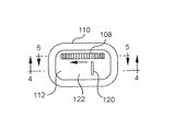
図1〜図7を参照すると、本発明の第1の例示的実施形態による試験ストリップを格納しかつ分与するための格納バイアル100は、試験ストリップのスタック104を格納するように構成された格納容器102と、容器内に回転可能に配置されたストリップローラ106と、容器内に回転可能に配置されたサムホイール(thumbwheel)108とを含む。ストリップローラ106は、試験ストリップのスタック104の1つの試験ストリップ142と接触する。サムホイール108が回転されるとき、ストリップローラ106が、ストリップローラ106と接触する試験ストリップ142を分与するために回転するように、サムホイール108は、ストリップローラ106を動作させる。
First Exemplary Embodiment Referring to FIGS. 1-7, a
格納容器102は、下方本体部分110、および下方本体部分110内に搭載された上方壁112を含む。格納容器102の下方本体部分110は、全体的に矩形であり、かつ試験ストリップのスタック104を格納するように構成された空洞114を形成する。試験ストリップ支持壁116は、容器の底部壁118から上方に延びる。試験ストリップ支持壁116は、格納容器102内に装填される試験ストリップのスタック104のための支持体を提供するのに十分に高い。試験ストリップ支持壁116は、それがストリップローラ106を妨げないように、ストリップローラ106に達しないで終端することができる。代わりに、試験ストリップ支持壁は、格納容器102の上部壁112の底部表面に延び、かつストリップローラ106(図14における要素331を参照)の設置および動作のための間隔を提供するための延ばされたスロットを有することができる。
The
格納容器102は、容器の内側の固有の相対湿度を調整するために乾燥剤が混入されたポリマーで作られることができる。その全体が参照によって本明細書に組み込まれる特許文献1は、1つの適切な乾燥剤が混入されたポリマーを開示する。代わりに、格納容器102は、インサート(insert)成形された乾燥剤を有するポリマーで作られることができ、または乾燥剤は、空洞114内に配置されることができる。
The
格納容器102の上部壁112は、好ましくは、より容易な製造およびアセンブリのために格納容器102の残りとは別個に作られる。試験ストリップ104が格納容器102内に装填された後、上部壁112は、超音波溶接によって、接着剤によって、機械的な係合(スナップはめ込みなど)によって、または当業者によって知られている任意の他の適切な方法によって格納容器102に固定されることができる。格納容器102の上部壁112は、それを通って試験ストリップが分与される分与スロット120を形成する。上部壁112の上部表面122は、試験ストリップを分与するためにサムホイール108を回転する方向を示すための表示136(矢印など)を持たせることができる。第1の支持部材124は、以下に詳細に議論されるように、ストリップローラ106を回転可能に支持するために上部壁112の底部表面126から延びる。第2の支持部材128は、また、上部壁112の底部表面から延びる。サムホイール108は、第2の支持部材128によって回転可能に支持され、かつサムホイール108は、格納容器102の上部壁112を通る第2のスロットを通って延びる。下方に延びる試験ストリップ支持壁は、それらが分与されているとき(図6参照)、分与スロット120内に試験ストリップを支持しかつ案内するために、試験ストリップ分与スロット120に隣接して配置されることができる(図14の831参照)。
The
格納容器102は、湿気または他の環境汚染物が格納容器102に入ることを妨げるために蓋138を備えることができる。蓋138は、別個の構成部品であり得るが、蓋138は、好ましくは蝶番122によって格納容器102に接続される。示される実施形態において、蓋138は、それが、リビング蝶番140によって格納容器121に接続されるように、格納容器102の下方本体部分110と一体に形成される。蓋138は、好ましくは、格納容器102の下方本体部分110と実質的に密閉シールを形成する。そのようなシールは、当業者には知られており、したがって、シールの詳細な記載は、簡潔性のために省略される。また、説明の便宜のために、蓋は図1にだけ示される。
The
圧縮ばねまたは板ばねなどのバイアス要素132は、格納容器102に格納された試験ストリップのスタック104をストリップローラ106と接触するように付勢する。プラットフォーム(platform)134は、試験ストリップのスタック104の長さに沿ってバイアス要素132によって生成される力を均一に分配するために、バイアス要素132と試験ストリップのスタック104との間に配置しても良い。しかしながら、試験ストリップが十分に堅固であるなら、バイアス要素132は、試験ストリップと直接接触しても良い。
A biasing
ストリップローラ106は、格納容器102の上部壁112から下方へ延びる第1の支持部材124によって回転可能に支持される。ストリップローラ106は、試験ストリップのスタック104内の試験ストリップ142の1つと接触する。示される実施形態(図4)において、ストリップローラ106は、最も右側の試験ストリップ142と係合する。好ましくは、ストリップローラ106は、試験ストリップの上方部分内の試験ストリップと係合する。ストリップローラ106の外側周囲表面144は、試験ストリップと摩擦係合しかつ分与するために、十分な摩擦係数を有するべきである。例えば、ストリップローラ106は、金属または成形されたプラスチックローラインサートに結合されたゴムで作ることができる。ストリップローラ歯車146は、ストリップローラ106の一方側に配置される。
The
サムホイール108は、第2の支持部材128によって回転可能に支持される。複数の歯車歯148は、サムホイール108の外側周囲の周りに配置され、かつサムホイール108上の歯車歯148は、ストリップローラ歯車146と係合する。歯車歯148は、また、ユーザが、親指、他の指などでサムホイール108をより好都合に動作することを可能にするために摩擦を提供する。
The
代わりに、図7に示されるように、格納容器102は、完全に自動化された試験ストリップ分与器で使用されることができる。この場合、自動化された試験ストリップ分与器は、ピニオン(pinion)歯車152を有するモータ150を備え、格納容器102は、ピニオン歯車152がサムホイール108と係合するように、自動化された試験ストリップ分与器内に配置される。自動化された試験ストリップ分与器は、所望であれば、試験ストリップ104を読み取る血液グルコースメータと組み合わされることができる。
Alternatively, as shown in FIG. 7, the
さらに、ラチェット(ratchet)または歯止めなどのロッキング部材154は、サムホイール108を係合するために格納容器102上に配置されることができる。ロッキング部材154は、サムホイール108が、一方向(すなわち分与方向)に回転することを可能にするが、サムホイール108が反対方向に回転することを妨げる。
In addition, a locking
本発明の第1の例示的実施形態による試験ストリップを格納しかつ分与するための格納バイアルを使用する方法は、以下に記載される。最初に、ストリップローラ106およびサムホイール108は、格納容器102の上方壁112上でそれぞれ第1の支持部材128および第2の支持部材130にアセンブリされる。試験ストリップのスタック104は、試験ストリップのスタック104が、プラットフォーム134と試験ストリップ支持壁130との間に配置されるように、格納容器102の下方本体部分110内に装填される。バイアス要素132は、プラットフォーム134と格納容器の反対側の壁との間の空洞114内に設置される。ストリップローラ106およびサムホイール108が取り付けられた上部壁112は、次に、格納容器102の下方本体にアセンブリされる。蓋138は、実質的に密閉シールを形成するために格納容器102上に配置される。格納バイアル100は、以降格納されることができ、試験ストリップのスタック104は、湿気などの環境危険物から保護される。典型的に、これらステップは、格納バイアルの最終使用者よりむしろ製造者によって行われる。
A method of using a storage vial for storing and dispensing test strips according to a first exemplary embodiment of the present invention is described below. Initially, the
試験ストリップを分与するために、使用者は、サムホイール108およびストリップ分与スロット120を露出するために蓋138を開く。使用者は、次に、使用者の指などによってサムホイール108を操作することによって、分与方向にサムホイール108を回転する。サムホイール108の回転時に、サムホイール108は、サムホイール108上の歯車歯148およびストリップローラ歯車146を介して、ストリップローラ106に回転力を伝達する。この結果、ストリップローラ106は回転する。ストリップローラ106は、試験ストリップのスタック104の1つの試験ストリップ142と接触し、かつストリップローラ106と接触された試験ストリップ142との間に生成される摩擦力によって、試験ストリップ分与スロット120を通して接触された試験ストリップ142を分与する。サムホイール108は、試験ストリップ142が格納容器102から完全に分与されて出るように回転されることができ、または試験ストリップ142は、使用者が、試験ストリップを完全に引き出しかつ試験ストリップを使用するために、露出された試験ストリップ142を把持することができるように、試験ストリップを露出するために格納容器102から部分的に分与されることができる。
To dispense the test strip, the user opens the
試験ストリップが、格納容器102から完全に分与されると、バイアス要素132は、新規の試験ストリップが、ストリップローラ106と接触して配置されるように、試験ストリップのスタック104内の残る試験ストリップをストリップローラ106の方に付勢する。したがって、次の試験ストリップを分与するために、使用者は、再びサムホイール108を回転する。所望の数の試験ストリップを分与した後、使用者は、次に、将来の使用のために残る試験ストリップを格納するために、格納容器102上に蓋を元の場所に戻すことができる。
When the test strip is fully dispensed from the
格納容器102内に格納された全ての格納された試験ストリップが分与された後、格納バイアル100は、廃棄されることができ、またはリサイクルのために製造者に戻されることができる。代わりに、格納容器102は、再使用可能であるように構成されることができる(例えば、上方壁112を下方本体部分110から取り外し可能とすることによって)。
After all stored test strips stored in the
第2の例示的実施形態
図8〜図12を参照すると、本発明の第2の例示的実施形態による試験ストリップを格納しかつ分与するための格納バイアル200は、試験ストリップのスタック204を格納するように構成された格納容器202と、格納容器202内に回転可能に配置されたストリップローラ206と、容器内に配置された押しボタン208とを含む。ストリップローラ206は、試験ストリップのスタック204の1つの試験ストリップ226と接触する。押しボタン208が押されるとき、ストリップローラ206が、ストリップローラと接触する試験ストリップ226を分与するために回転するように、押しボタン208は、歯車列230によってストリップローラ206と連結される。
Second Exemplary Embodiment Referring to FIGS. 8-12, a
格納容器202は、下方本体部分210、および下方本体部分210内に搭載された上方壁212を含む。格納容器202の下方本体部分210は、本発明の第1の例示的実施形態の格納容器100の下方本体部分110と実質的に同一に構成される。したがって、下方本体部分210の詳細な記載は繰り返されない。
The
格納容器202の上部壁212は、それを通って試験ストリップが分与される試験ストリップ分与スロット216を有する。第1の支持部材218は、以下に詳細に議論されるように、ストリップローラ206を回転可能に支持するために上部壁212の底部表面220から延びる。第2の支持部材222は、中間歯車232を回転可能に支持するために、上部壁212の底部表面220から延びる。
The
押しボタン208は、第1の端部234および第2の端部236を有する。押しボタン208の第1の端部234は、それが使用者によって操作されることができるように、格納容器202の上方壁212内に配置されたスロットを通して延びる。押しボタン208の第2の端部236は、格納容器202の空洞214の内側に配置される。ラック歯車238は、押しボタン208の第2の端部236の近くで、押しボタン208の長さに沿って形成される。
The
押しボタンは、静止位置(例えば図10に示される)と分与位置との間で移動可能である。拡張ばねなどのバイアス要素240は、上方壁212と押しボタン208との間に配置される。バイアス要素240は、押しボタン208を静止位置へ付勢する。
The push button is movable between a rest position (eg shown in FIG. 10) and a dispensing position. A biasing element 240, such as an expansion spring, is disposed between the
押しボタン208は、押しボタンの一方側に配置された少なくとも1つのトラック242を有し、かつ押しボタン208の両側に配置されたトラックを有することができる。トラック242は、押しボタン208が、試験ストリップを分与するために押されるとき、押しボタン208上のラック歯車238が、中間歯車232と係合するように、押しボタン208の移動を案内するように構成される。押しボタン208が解放されるとき、トラック242は、ラック歯車238を中間歯車232から分離させるように構成される。したがって、押しボタン208は、中間歯車232を回転することなく、分与位置から静止位置へ復元されることができる。
The
中間歯車232は、格納容器202の上方壁212の底部表面220から下方へ延びる第2の支持部材222上に回転可能に配置される。中間歯車232は、歯車を動作式に接続しかつ歯車列230を形成するために、押しボタン208上のラック歯車238とストリップローラ206上のストリップローラ歯車228との間に配置される。
The
ストリップローラ206は、格納容器202の上方壁212の底部表面220から下方に延びる第1の支持部材218によって回転可能に支持される。ストリップローラ206は、本発明の第1の例示的実施形態のストリップローラ106とほぼ同一に構成される。したがって、ストリップローラ206の詳細な記載は、繰り返されない。
The
本発明の第2の例示的実施形態による試験ストリップを格納しかつ分与するための格納バイアル200を使用する方法は、以下に記載される。最初に、ストリップローラ206、押しボタン208、バイアス要素240、および中間歯車232は、格納容器202の上方壁212にアセンブリされる。試験ストリップのスタック204は、試験ストリップのスタック204が、プラットフォーム246(およびバイアス要素232)と試験ストリップ支持壁248との間に配置されるように、格納容器202の下方本体部分210内に装填される。設置された構成要素を有する上部壁212は、次に、ストリップローラ206が、試験ストリップのスタック204の1つの試験ストリップ226と係合するように、格納容器202の下方本体部分210にアセンブリされる。その後、蓋224を閉じることができ、試験ストリップのスタックを、所望な限り長く格納することができる。
A method of using the
試験ストリップを分与するために、使用者は、蓋224を開き、かつ静止位置から分与位置に押しボタン208を移動するために押しボタン208を押す。最初に、押しボタン208上のラック242は、ラック歯車238を中間歯車232に係合させる。したがって、押しボタン208の移動は、ラック歯車238に中間歯車232を回転させる。中間歯車232の回転は、ストリップローラ歯車228を回転させ、ストリップローラ206に、ストリップローラ206が接触する試験ストリップ226を分与させる。押しボタン208は、試験ストリップ226が格納容器202から完全に分与されて出るように構成することができ、または試験ストリップ226は、使用者が、試験ストリップを格納容器202から完全に引き出すために、露出された試験ストリップ226を把持することができるように、試験ストリップを露出するために格納容器202から部分的に分与され得る。
To dispense the test strip, the user opens the
試験ストリップ226が分与されると、バイアス要素244は、新規の試験ストリップが、分与されることができるように、試験ストリップ支持壁248に対してプラットフォーム246および試験ストリップのスタック204を付勢する。
As
使用者が、押しボタン208を解放するとき、押しボタン上のトラック242の構成は、押しボタン208を、ラック歯車238に沿って中間歯車232から離してかつ中間歯車232との係合を解く。したがって、押しボタン208は、中間歯車232およびストリップローラ歯車228を逆方向に回転させずに、静止位置に戻ることができる。
When the user releases the
第3の例示的実施形態
図13〜図14を参照すると、本発明の第3の例示的実施形態による試験ストリップを格納しかつ分与するための格納バイアル300は、試験ストリップのスタックを格納するように構成された格納容器302と、格納容器302内に回転可能に配置されたストリップローラ306と、格納容器302内に配置された押しボタン308とを含む。ストリップローラ306は、試験ストリップのスタックの1つの試験ストリップと接触する。押しボタン308が押されるとき、ストリップローラ306が、ストリップローラ306と接触する試験ストリップを分与するために回転するように、押しボタン308は、歯車列によってストリップローラ306と連結される。
Third Exemplary Embodiment Referring to FIGS. 13-14, a
本発明の第3の例示的実施形態の格納容器302は、歯車列の中間歯車316および押しボタン308の構成を除いて、本発明の第2の例示的実施形態の格納容器202とほぼ同一である。
The
本発明のこの実施形態において、押しボタン308は、中間歯車316にラック歯車を係合しかつ中間歯車316からラック歯車を分離するためのトラックを有さない。実際、押しボタン308は、格納容器302の下方本体部分304の外側壁の内表面に配置されかつ格納容器302の下方本体部分304の外側壁の内表面に配置された押しボタンガイドトラック310によって案内される延長されたガイドピン(図示せず)を有する。ガイドトラック310は、押しボタン部材が、実質的に真っ直ぐ格納容器302内にかつ格納容器302から外に移動するように、下方本体部分の縁部にほぼ平行である。
In this embodiment of the invention, the
本発明のこの実施形態の中間歯車316は、格納容器の上部壁から延びる支持部材によって支持されていない。その代わり、中間歯車316は、格納容器302の下方本体部分304の外側壁の内表面に形成された一対の中間歯車ガイドトラック312内に配置されかつ中間歯車ガイドトラック312によって案内される延長されたシャフト部分(図示せず)を有する。したがって、中間歯車316は、中間歯車ガイドトラック312の長さに沿って直線的に自由に移動する。
The
本発明の第3の例示的実施形態による試験ストリップを格納しかつ分与するための格納バイアル300を使用する方法は、以下に記載される。最初に、格納バイアル300は、試験ストリップのスタックを装填され、かつ実質的に上述と同じ方法でアセンブリされる。
A method of using a
試験ストリップを分与するために、使用者は、静止位置から分与位置に押しボタン308を移動するために押しボタン308を押す。最初に、押しボタン308上のラック歯車は、中間歯車316に係合し、中間歯車316は、中間歯車ガイドトラック312の下側端部314へ向かって直線的に移動する。中間歯車ガイドトラック312の下側端部314に到達すると、ガイドトラック312は、中間歯車316の任意のさらなる線形移動を防止する。したがって、押しボタン308のさらなる移動は、押しボタン308上のラック歯車に中間歯車316を回転させる。中間歯車316の回転は、ストリップローラ歯車を回転させ、ストリップローラ306に試験ストリップを分与させる。押しボタン308は、試験ストリップを完全に分与するように構成されることができ、または試験ストリップは、使用者が、試験ストリップを格納容器302から完全に引き出すために、露出された試験ストリップを把持することができるように、試験ストリップを露出するために格納容器302から部分的に分与され得る。
To dispense the test strip, the user presses
使用者が、押しボタン308を解放するとき、バイアス要素は、押しボタン308を、分与位置から静止位置に戻るように付勢する。静止位置へ向かう押しボタン308の初期に移動の間に、中間歯車316は、中間歯車ガイドトラック312に沿って、ガイドトラックの上方端部へ向かう移動に変換する。中間歯車316が、十分に離れて移動するとき、それは、ストリップローラ歯車を分離する。したがって、押しボタン308は、ストリップローラ歯車が反対方向に回転することなく、静止位置に戻ることができる。
When the user releases the
第4の例示的実施形態
図15〜図17を参照すると、本発明の第4の例示的実施形態による試験ストリップを格納しかつ分与するための格納バイアル400は、試験ストリップのスタック404を格納するように構成された格納容器402と、蝶番408によって格納容器に接続された蓋406と、蓋406に動作式に接続されたリンク装置アセンブリ410とを含む。蓋406が開かれたとき、リンク装置アセンブリ410は、試験ストリップのスタック404の1つの試験ストリップ412と係合し、かつ試験ストリップ412を分与する。
Fourth Exemplary Embodiment Referring to FIGS. 15-17, a
格納容器402は、全体的に矩形である下方本体部分414を有し、かつ試験ストリップのスタック404を格納するように構成された空洞416を形成する。格納容器402は、前述されたように任意の適切な材料で形成される。
The
格納バイアル400は、湿気または他の環境汚染物が格納容器に入ることを妨げるために蓋406を備える。蓋406は、蝶番408によって格納バイアルに接続される。示される実施形態において、蓋406が、リビング蝶番408に接続されるように、格納容器の下方本体部分と一体に形成される。しかしながら、任意のタイプの蝶番構成が使用されることができる。蓋406は、好ましくは、格納容器402の下方本体部分414と密閉シールを形成する。
The
リンク装置アセンブリ410は、蓋406に接続された第1のアーム部材418と、リビング蝶番428によって第1のアーム部材418に接続された第2のアーム部材420と、リビング蝶番428によって第2のアーム部材420に接続された第3のアーム部材422とを含む。第1のアーム部材418は、全体的にV形状部材である。示される実施形態において、V形状部材の2つの脚部は、互いに対して鈍角を形成する。第1のアーム部材418は、熱ステーキング(staking)、超音波溶接、機械的な取付け、または当業者により知られている任意の他の適切な方法によって蓋406に取り付けられる。
The
第2のアーム部材420は、第2のアーム部材の両端部でリビング蝶番428によって第1のアーム部材418および第3のアーム部材422を結合する。リビング蝶番の使用は、より低い製造価格などのいくつかの利点を提供するが、アームも、他のタイプの蝶番によって結合されることができることは理解されるべきである。
The
第3のアーム部材422は、格納容器402の下方本体部分414の側壁内に配置されたレール内に配置されかつレール内で移動するように構成された、ガイドピンなどのガイド部材430を有する。第3のアーム部材422は、試験ストリップのスタック404の1つの試験ストリップ412の下方縁部に接触するように構成された下方接触部材426を有する。特に、図示された実施形態において、第3のアーム部材422は、最も右側の試験ストリップ412の下方縁部と接触する。
The
図示のように、一組の第1、第2、および第3のアーム部材は、格納容器402の前方側(図において手前側)に提供される。安定性のために、第1の組の第1、第2、および第3のアーム部材と実質的に同一である第2の組の第1、第2、および第3のアーム部材は、格納容器402の後方側(図において背面側)に配置されることができる。
As shown, a set of first, second, and third arm members are provided on the front side (front side in the drawing) of the
本発明の第4の例示的実施形態による試験ストリップを格納しかつ分与するための格納バイアル400を使用する方法は、以下に記載される。最初に、蓋406が開かれ、試験ストリップのスタック404は、プラットフォーム432と格納容器402の外側壁434との間で容器内に装填され、かつ蓋406が閉じられる。蓋406が閉じられると、リンク装置アセンブリ410は、静止位置に配置される。静止位置において、第3のアーム部材422は、格納容器の底部に配置され、かつ下方接触部材426は、最も右側の試験ストリップ412の底部縁部の下側に配置される。
A method of using a
(0083)
試験ストリップを分与するために、使用者は、格納容器402の蓋406を開く。蓋406を開くことは、第1のアーム部材418を格納容器まで回転させかつ格納容器の外に回転させる。第1のアーム部材418に接続される第2のアーム部材420および第3のアーム部材422もまた上昇される。第3のアーム部材422は、ガイド部材430とガイドレールとの協働のために実質的に垂直に上方に移動し、かつ分与位置まで上昇させられる。第3のアーム部材422の下方接触部材426は、試験ストリップ412の下に配置されるので、それは、上昇しかつ試験ストリップ412を分与する。第3のアーム部材422が、分与位置に到達すると、使用者は、試験ストリップを把持しかつ分与された試験ストリップ412を取り出すことができる。第1のアーム部材418、第2のアーム部材420、および第3のアーム部材422は、試験ストリップ412を格納容器402の外に完全に分与するように構成されることができ、または試験ストリップ412は、使用者が、試験ストリップを格納容器402から完全に引き出しかつ試験ストリップを使用するために露出された試験ストリップ412を把持することができるように、試験ストリップを露出するために格納容器402から部分的に分与されることができる。
(0083)
To dispense the test strip, the user opens the
試験ストリップ412が分与された後、使用者は、次に蓋406を閉じることができる。蓋406を閉じることは、リンク装置アセンブリ410をその静止位置に戻させる。リンク装置アセンブリ410、および特に第3のアーム部材422が、静止位置に到達するとき、バイアス要素436は、新規な試験ストリップが、新規な試験ストリップの下方接触部材426上に配置されるように、試験ストリップのスタック404を外側壁434に向かって付勢する。したがって、格納バイアル400は、次の試験ストリップを分与する準備がなされる。
After the
第5の例示的実施形態
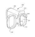
図18〜図20を参照すると、本発明の第5の例示的実施形態による試験ストリップを格納しかつ分与するための格納バイアル500は、試験ストリップのスタックを格納するように構成された格納容器502と、蝶番506によって格納容器502に接続された蓋504と、蓋504に動作式に接続されたリンク装置アセンブリ508とを含む。蓋504が開かれたとき、リンク装置アセンブリ508は、試験ストリップのスタックの1つの試験ストリップ510と係合し、かつ試験ストリップを分与する。
Fifth Exemplary Embodiment Referring to FIGS. 18-20, a
この実施形態の格納容器502および蓋504は、第4の例示的実施形態の格納容器502および蓋504と全体的に同一に構成される。
The
リンク装置アセンブリ508は、少なくとも1つのスライダアーム(slider arm)512、少なくとも1つの第1のリンク装置部材514、および少なくとも1つの第2のリンク装置部材516を含む。図示される実施形態において、一対のスライダアーム512、一対の第1のリンク装置部材514、および一対の第2のリンク装置部材516は、リンク装置アセンブリの安定性および信頼性を増大するように提供される。
スライダアーム512の第1の端部518は、蓋504に旋回可能に接続される。スライダアーム512の第2の端部520は、第1のリンク装置部材514に旋回可能に接続される。各スライダアーム512は、格納容器502上に配置されるガイドボス(guide boss)536を係合するスロット522を有する。
A
第1のリンク装置部材514の第1の端部524は、スライダアーム512の第2の端部520に旋回可能に接続され、かつ第1のリンク装置部材514の第2の端部526は、第2のリンク装置部材516に旋回可能に接続される。
The
第2のリンク装置部材516は、格納容器502の側壁内に配置されたガイドレール内に配置されかつガイドレール内で移動するように構成された、ガイドピンなどのガイド部材528を有する。第2のリンク装置部材516の第1の端部530は、第1のリンク装置部材514の第2の端部526に接続される。下方接触部材534は、第2のリンク装置部材516の第2の端部532間に配置される。下方接触部材は、蓋504が開かれたときに、試験ストリップ510が分与されるように、1つの試験ストリップ510と接触する。
The second
本発明の第5の例示的実施形態による試験ストリップを格納しかつ分与するための格納バイアル500を使用する方法は、以下に記載される。最初に、蓋504が開かれ、試験ストリップのスタックは、格納容器502内に装填され、かつ蓋504が閉じられる。蓋504が閉じられて、リンク装置アセンブリ508は、静止位置に配置される。静止位置において、第2のリンク装置部材516は、格納容器502の底部に配置され、かつ下方接触部材534は、最も右側の試験ストリップ510の底部縁部下方縁部の下側に配置される。
A method of using a
試験ストリップを分与するために、使用者は、格納容器502の蓋504を開く。蓋504を開くことは、スライダアーム512を格納容器502まで回転させかつ格納容器502の外に回転させる。スライダアーム512は、所定の経路に沿って、ガイドボス536とスライダアーム512内のスロットとの協働によって案内される。スライダアーム512の第2の端部520は、第1のリンク装置部材514を引き、第1のリンク装置部材514は、次に第2のリンク装置部材516を引く。第2のリンク装置部材516は、ガイド部材528とガイドレールとの協働のために格納容器502の内側で実質的に垂直に上方に移動し、かつ分与位置まで上昇させられる。下方接触部材534は、試験ストリップの下に配置されるので、それは、上昇しかつ試験ストリップを分与する。第2のリンク装置部材516が、分与位置に到達すると、使用者は、試験ストリップを把持しかつ分与された試験ストリップを取り出すことができる。スライダアーム512、第1のリンク装置部材514、および第2のリンク装置部材516は、試験ストリップを格納容器502の外に完全に分与するように構成されることができ、または試験ストリップは、使用者が、試験ストリップを格納容器から完全に引き出しかつ試験ストリップを使用するために露出された試験ストリップを把持することができるように、試験ストリップを露出するために格納容器502から部分的に分与されることができる。
To dispense the test strip, the user opens the
試験ストリップが分与された後、使用者は、次に蓋504を閉じることができる。蓋504を閉じることは、リンク装置アセンブリ508をその静止位置に戻させる。リンク装置アセンブリ508、および特に第2のリンク装置部材516が、静止位置に到達するとき、バイアス要素は、新規な試験ストリップが、下方接触部材上に配置されるように、試験ストリップのスタックを格納容器502の側壁に向かって付勢する。したがって、格納容器502は、次の試験ストリップを分与する準備がされている。
After the test strip is dispensed, the user can then close the
第6の例示的実施形態
図21を参照すると、本発明の第6の例示的実施形態による試験ストリップを格納しかつ分与するための格納バイアル600は、試験ストリップのスタックを格納するように構成された格納容器602と、螺旋プッシャばね(spiral pusher spring)604と、サムホイール606の回転が、ばねを試験ストリップのスタックの1つの試験ストリップを分与させるように、歯車列628によって螺旋プッシャばね604に接続されたサムホイール606とを含む。
Sixth Exemplary Embodiment Referring to FIG. 21, a
格納容器602は、全体的に矩形であり、かつ試験ストリップのスタックを格納するためのカートリッジ610を受けるように構成された空洞612を形成する。格納容器602は、前述されたように任意の適切な材料で形成される。
The
格納バイアル600は、湿気および他の環境汚染物が格納容器602に入ることを妨げるために蓋608を備える。蓋608は、リビング蝶番などの任意の適切なタイプの蝶番によって格納バイアルに接続されることができる。
The
カートリッジ610は、格納容器602内の空洞に挿入される。螺旋プッシャばね604および結合される歯車列628は、カートリッジ610内に配置される。カートリッジ610内の空洞612は、試験ストリップのスタックを保持するように構成され、かつプラットフォームならびにバイアス要素は、カートリッジ610の1つの壁に向かって要素のスタックを付勢するために空洞内に配置される。カートリッジ610は、格納容器602から取り外し可能でありまたはそこに恒久的に固定されることができる。
The
螺旋プッシャばね604は、円筒状ばねドラム614の周りに巻かれる。螺旋プッシャばね604の第1の端部616は、カートリッジ610内に形成されたガイドトラック618内に配置される。螺旋プッシャばね604の第2の端部620は、円筒状ばねドラム614に固定される。螺旋プッシャばね604の第1の端部616は、試験ストリップの縁部と接触するように構成される。したがって、ばねドラム614が回転されたとき、螺旋プッシャばね604の第1の端部616は、延長され、かつ試験ストリップを分与するためにガイドトラック618に沿って移動する。
The
示される実施形態において、歯車列628は、サムホイール駆動歯車606、第1のアイドラ(ideler)歯車622、第2のアイドラ歯車624、およびばねドラム駆動歯車626を備える。サムホイール駆動歯車606は、使用者がサムホイール606を操作することができるように、格納容器602の外側に部分的に露出される。第1のアイドラ歯車622および第2のアイドラ歯車624は、サムホイール606と係合し、サムホイール606によって生成される回転力をばねドラム駆動歯車626に伝達する。歯車列628は、任意の所望の歯車比で構成されることができる。
In the illustrated embodiment, the
本発明の第6の例示的実施形態による試験ストリップを格納しかつ分与するための格納バイアル600を使用する方法は、以下に記載される。最初に、試験ストリップのスタックは、カートリッジ610内に装填され、螺旋プッシャばね604は、最初の静止位置内に引き込まれ、かつカートリッジは、格納容器602内に挿入される。静止位置において、螺旋プッシャばね604は、ばねの端部が、格納容器602の底部に配置され、かつ試験ストリップの一端部の下方縁部下にあるように、引き込まれる。
A method of using a
試験ストリップを分与するために、使用者は、分与方向に露出されたサムホイール606を回転する。サムホイール606の回転力は、歯車列628を介して螺旋プッシャばね604に伝達される。螺旋プッシャばね604は、伸張されて試験ストリップを分与する。サムホイール606は、試験ストリップが、格納容器602の外に完全に分与するように回転されることができ、または試験ストリップは、使用者が、試験ストリップを完全に引き出しかつ試験ストリップを使用するために露出された試験ストリップを把持することができるように、試験ストリップを露出するために格納容器602から部分的に分与されることができる。
To dispense the test strip, the user rotates the
試験ストリップが分与された後、使用者は、次に、螺旋プッシャばね604をその静止位置に戻すために、分与方向に対する反対方向にサムホイール606を回転することができる。代わりに、螺旋プッシャばね604の固有のばね力は、自動的にそれをその静止位置へ戻させることができる。螺旋プッシャばね604が静止位置に到達するとき、バイアス要素は、新規の試験ストリップが、プッシャばねの端部上に配置されるように、試験ストリップのスタックを螺旋ばねに向かって付勢する。その結果、格納容器602は、次の試験ストリップを分与する準備がなされる。
After the test strip is dispensed, the user can then rotate the
第7の例示的実施形態
図22を参照すると、本発明の第7の例示的実施形態による試験ストリップを格納しかつ分与するための格納バイアル700は、試験ストリップのスタックを格納するように構成された格納容器702と、試験ストリップのスタックの1つの試験ストリップと接触するように構成されたばね704と、ばね704に接続されたラック706と、ラック706に係合するピニオン708と、サムホイール710の回転が、ラック706を変位し、かつばね704を接触された試験ストリップを分与させるように、ピニオン708と係合するサムホイール710とを含む。
Seventh Exemplary Embodiment Referring to FIG. 22, a
この実施形態の格納容器702および蓋は、第6の例示的実施形態の格納容器702および蓋と全体的に同一に構成される。
The
カートリッジ712は、格納容器702内の空洞714に挿入される。カートリッジ712は、試験ストリップのスタックを保持するように構成された空洞を有し、かつプラットフォームならびにバイアス要素は、カートリッジ712の1つの壁に向かって試験ストリップのスタックを付勢するためにカートリッジ712内に配置される。カートリッジ712は、格納容器602から取り外し可能でありまたはそこに恒久的に固定されることができる。
The
ばね704は、カートリッジ712内に形成されたガイドトラック722内に配置される。ばね704の第1の端部716は、ガイドトラック722によって案内され、かつ試験ストリップの縁部と接触するように構成される。ばね704の第2の端部718は、ラック706に固定される。
The
ラック706は、格納容器702内で直線的に移動可能である。ラック706は、ラックの一方側に配置されたラック歯車720を有する。
The
ピニオン歯車708は、カートリッジ712上に回転可能に配置され、かつラック歯車720と係合する。
The
サムホイール710は、また、カートリッジ712上に回転可能に配置され、かつピニオン歯車708と係合する。したがって、サムホイール710が回転されるとき、ピニオン歯車708は回転し、かつラック706は線形に変位する。したがって、取り付けられたばね704の第1の端部は、ガイドトラック722に沿って移動される。
The
本発明の第7の例示的実施形態による試験ストリップを格納しかつ分与するための格納バイアルを使用する方法は、以下に記載される。最初に、試験ストリップのスタックは、カートリッジ712内に装填され、プッシャばね704およびラック706は、最初の静止位置内に配置され、かつカートリッジは、格納容器702内に挿入される。静止位置において、ラック706およびプッシャばね704は、ばね704の端部が、格納容器702の底部に配置され、かつ試験ストリップの一縁部の下方縁部の下方にあるように、引き込まれる。
A method of using a storage vial for storing and dispensing test strips according to a seventh exemplary embodiment of the present invention is described below. Initially, a stack of test strips is loaded into the
試験ストリップを分与するために、使用者は、分与方向に露出されたサムホイール710を回転する。サムホイール710の回転力は、ピニオン歯車708に伝達され、かつピニオン歯車708は、ピニオン歯車708の回転力をラック706の線形移動に変換するためにラック歯車706と係合する。ラック歯車706の線形移動は、プッシャばね704を伸張し、かつ試験ストリップを分与する。サムホイール710は、試験ストリップが、格納容器702の外に完全に分与されるように回転されることができ、または試験ストリップは、使用者が、試験ストリップを完全に引き出しかつ試験ストリップを使用するために露出された試験ストリップを把持することができるように、試験ストリップを露出するために格納容器702から部分的に分与されることができる。
To dispense the test strip, the user rotates the
試験ストリップが分与された後、使用者は、次に、プッシャばね704をその静止位置に戻すために、分与方向に対する反対方向にサムホイール710を回転することができる。一方、プッシャばねは、自動的にその静止位置へ戻ることができる。プッシャばね704が静止位置に到達するとき、バイアス要素は、新規の試験ストリップが、プッシャばね704の端部上に配置されるように、試験ストリップのスタックをプッシャばね704に向かって付勢する。その結果、格納容器702は、次の試験ストリップを分与する準備がなされる。
After the test strip has been dispensed, the user can then rotate the
第8の例示的実施形態
図23〜図24を参照すると、本発明の第8の例示的実施形態による試験ストリップを格納しかつ分与するための格納バイアル800は、試験ストリップラックのスタックを格納するように構成された格納容器802と、試験ストリップのスタックの1つの試験ストリップと接触するように構成されたばね804と、旋回点808の周りで旋回するレバーアーム806を含む。レバーアーム806の第1の端部810は、レバーの旋回が、ばね804に接触する試験ストリップを分与させるように、ばね804を駆動するためにばね804に接続される。
Eighth Exemplary Embodiment Referring to FIGS. 23-24, a
この実施形態の格納容器802および蓋(図示せず)は、第6の例示的実施形態の格納容器602および蓋608と全体的に同一に構成される。
The
カートリッジ814は、格納容器802内の空洞内に挿入される。カートリッジ814内の空洞は、試験ストリップのスタックを保持するように構成され、かつプラットフォームならびにバイアス要素は、カートリッジの1つの壁に向かって試験ストリップのスタックを付勢するために空洞内に配置される。カートリッジ814は、格納容器802から取り外し可能でありまたはそこに恒久的に固定されることができる。
The
ばね804は、カートリッジ814によって形成されたガイドトラック818内に配置される。ばね804の第1の端部820は、ガイドトラック818によって案内され、かつ試験ストリップ816の縁部と接触するように構成される。ばね804の第2の端部822は、レバーアーム806の第1の端部810に固定される。
The
レバーアーム806は、カートリッジ上の旋回点808の周りに旋回可能に配置される。レバーアーム806の第2の端部824は、使用者がレバーアーム806を操作することができるように、カートリッジの上方端部上に延びる。
The
本発明の第8の例示的実施形態による試験ストリップを格納しかつ分与するための格納バイアル800を使用する方法は、以下に記載される。最初に、試験ストリップのスタックは、カートリッジ814内に装填され、レバーアーム806およびプッシャばね804は、最初の静止位置内に配置され、かつカートリッジは、格納容器802内に挿入される。静止位置において、レバーアーム806は、格納容器802の一方側に旋回され、かつプッシャばね804は、ばね804の端部が、格納容器802の底部に配置され、かつ試験ストリップの一縁部の下方縁部の下方にあるように、引き込まれる。
A method of using a
試験ストリップを分与するために、使用者は、レバーアーム806を旋回するためにレバーアーム806を押す。レバーアーム806の旋回は、プッシャばね804をガイドトラックに沿って延ばさせかつ試験ストリップを分与させる。レバーアーム806は、使用者が、試験ストリップを把持しかつ分与された試験ストリップを取り出すために十分に離れて旋回させられる。
To dispense the test strip, the user pushes
試験ストリップが分与された後、使用者は、次に、レバーアーム806をその最初の静止位置に戻すために旋回することができる。一方、レバーアームは、自動的にその静止位置へ戻ることができる。レバーアーム806が静止位置に到達するとき、バイアス要素は、新規の試験ストリップが、プッシャばね804の端部上に配置されるように、試験ストリップのスタックをプッシャばね804に向かって付勢する。したがって、格納容器802は、次の試験ストリップを分与する準備がなされる。
After the test strip is dispensed, the user can then pivot to return the
様々な実施形態は、本発明を示すために選択されたが、様々な変更および修正は、添付の特許請求の範囲に規定される本発明の範囲から逸脱することなく行われることができることは、当業者には理解されるであろう。 While various embodiments have been selected to illustrate the present invention, it is understood that various changes and modifications can be made without departing from the scope of the invention as defined in the appended claims. Those skilled in the art will appreciate.
100 格納バイアル
102 格納容器
104 スタック
106 ストリップローラ
108 サムホイール
120 スロット
132 バイアス要素
140 リビング蝶番
150 モータ
152 ピニオン
154 ロッキング部材
208 押しボタン
206 ストリップローラ
224 蓋
228 ストリップローラ歯車
232 中間歯車
238 ラック歯車
244 バイアス要素
418 第1のアーム部材
420 第2のアーム部材
422 第3のアーム部材
DESCRIPTION OF
Claims (9)
試験ストリップのスタックを格納するように構成された容器と、
蝶番によって前記容器に接続された蓋と、
前記蓋に動作式に接続され、前記試験ストリップのスタックの1つの試験ストリップに接触するように構成されたリンク装置アセンブリとを備え、
前記蓋が開かれたとき、試験ストリップが分与され、
前記リンク装置アセンブリは、引上げ部材を備え、前記引上げ部材は、試験ストリップのスタックの1つの試験ストリップの縁部に接触するための下方接触部材を備え、
前記引上げ部材は、引上げ部材の移動をガイドするために容器のガイドレールの中で移動するガイド部材を備え、前記ガイドレールは、容器の側壁上に配置されており、
前記リンク装置アセンブリは、前記ストリップを分与する間、前記蓋に接続された状態を維持することを特徴とする装置。 An apparatus for storing and dispensing test strips,
A container configured to store a stack of test strips;
A lid connected to the container by a hinge;
A linkage assembly operatively connected to the lid and configured to contact one test strip of the stack of test strips;
When the lid is opened, a test strip is dispensed,
The linkage assembly comprises a pulling member, the pulling member comprising a lower contact member for contacting an edge of one test strip of the stack of test strips;
The pulling member comprises a guide member that moves in a guide rail of the container to guide the movement of the pulling member, the guide rail being disposed on a side wall of the container ;
The apparatus is characterized in that the linkage assembly remains connected to the lid while dispensing the strip .
前記蓋に接続された第1のアーム部材と、
リビング蝶番によって前記第1のアーム部材に接続された第2のアーム部材と、
リビング蝶番によって前記第2のアーム部材に接続された第3のアーム部材とを備え、前記第3のアーム部材は、前記引上げ部材であり、前記蓋が開かれたときに、前記試験ストリップが分与されるように、前記1つの試験ストリップに接触することを特徴とする請求項1に記載の装置。 The link assembly is
A first arm member connected to the lid;
A second arm member connected to the first arm member by a living hinge;
And a third arm member connected to the second arm member by a living hinge, wherein the third arm member is the pulling member, and the test strip is separated when the lid is opened. The apparatus of claim 1, wherein the apparatus contacts the one test strip as provided.
前記蓋に接続され、かつ前記容器上のボスに係合するスロットを有するスライダアームと、
前記スライダアームに接続される第1のリンク装置部材と、
前記第1のリンク装置部材に接続された第2のリンク装置部材と、を備え、前記第2のリンク装置部材は、前記引上げ部材であり、前記蓋が開かれたときに、前記試験ストリップが分与されるように、前記1つの試験ストリップと接触することを特徴とする請求項1に記載の装置。 The link assembly is
A slider arm having a slot connected to the lid and engaging a boss on the container;
A first link device member connected to the slider arm;
A second link device member connected to the first link device member, wherein the second link device member is the pulling member, and the test strip is opened when the lid is opened. The apparatus of claim 1, wherein the apparatus is in contact with the one test strip to be dispensed.
試験ストリップのスタックを形成するために複数の試験ストリップを配置するステップと、
前記複数の試験ストリップを格納容器内に格納するステップと、
前記試験ストリップのスタックを分与位置へ向けて付勢するステップと、
前記試験ストリップのスタックをリンク装置アセンブリに係合するステップと、
前記格納容器の蓋を開けることにより、前記係合された試験ストリップを分与するために前記リンク装置アセンブリを作動するステップであって、前記蓋は前記リンク装置アセンブリに動作式に係合するステップと、
他の試験ストリップが分与位置に配置されるように、残りの試験ストリップを前記分与位置に向けて付勢するステップと、を含み、
前記リンク装置アセンブリは、溝を有するスライダアームを備え、かつ前記容器は前記溝に係合されるガイドボスを備え、
前記作動操作は、前記ガイドボスと前記スライダアームとの協働によって前記リンク装置アセンブリの移動を案内することを備えることを特徴とする方法。 A method for storing and dispensing test strips, comprising:
Placing a plurality of test strips to form a stack of test strips;
Storing the plurality of test strips in a containment vessel;
Urging the stack of test strips toward a dispensing position;
Engaging the stack of test strips with a linkage assembly ;
By opening the lid of the storage container, comprising the steps of actuating said linkage assembly for dispensing said engaged with the test strip, step the lid which engages the operation expression to the link assembly When,
Urging the remaining test strips toward the dispensing position such that other test strips are placed in the dispensing position;
The link device assembly comprises a slider arm having a groove, and the container comprises a guide boss engaged with the groove;
The actuating operation comprises guiding movement of the linkage assembly by cooperation of the guide boss and the slider arm.
Applications Claiming Priority (2)
| Application Number | Priority Date | Filing Date | Title |
|---|---|---|---|
| US11/430,178 | 2006-05-09 | ||
| US11/430,178 US7887757B2 (en) | 2006-05-09 | 2006-05-09 | Method and apparatus for dispensing diagnostic test strips |
Related Parent Applications (1)
| Application Number | Title | Priority Date | Filing Date |
|---|---|---|---|
| JP2007124509A Division JP5268281B2 (en) | 2006-05-09 | 2007-05-09 | Method and apparatus for dispensing diagnostic test strips |
Publications (2)
| Publication Number | Publication Date |
|---|---|
| JP2013154962A JP2013154962A (en) | 2013-08-15 |
| JP5657740B2 true JP5657740B2 (en) | 2015-01-21 |
Family
ID=38441865
Family Applications (3)
| Application Number | Title | Priority Date | Filing Date |
|---|---|---|---|
| JP2007124509A Active JP5268281B2 (en) | 2006-05-09 | 2007-05-09 | Method and apparatus for dispensing diagnostic test strips |
| JP2013097687A Active JP5657740B2 (en) | 2006-05-09 | 2013-05-07 | Method and apparatus for dispensing diagnostic test strips |
| JP2013097699A Active JP5948279B2 (en) | 2006-05-09 | 2013-05-07 | Method and apparatus for dispensing diagnostic test strips |
Family Applications Before (1)
| Application Number | Title | Priority Date | Filing Date |
|---|---|---|---|
| JP2007124509A Active JP5268281B2 (en) | 2006-05-09 | 2007-05-09 | Method and apparatus for dispensing diagnostic test strips |
Family Applications After (1)
| Application Number | Title | Priority Date | Filing Date |
|---|---|---|---|
| JP2013097699A Active JP5948279B2 (en) | 2006-05-09 | 2013-05-07 | Method and apparatus for dispensing diagnostic test strips |
Country Status (7)
| Country | Link |
|---|---|
| US (4) | US7887757B2 (en) |
| EP (3) | EP1854738B1 (en) |
| JP (3) | JP5268281B2 (en) |
| AT (1) | ATE506287T1 (en) |
| CA (1) | CA2587993C (en) |
| DE (1) | DE602007013964D1 (en) |
| ES (3) | ES2407649T3 (en) |
Families Citing this family (47)
| Publication number | Priority date | Publication date | Assignee | Title |
|---|---|---|---|---|
| US7858046B2 (en) * | 2006-09-14 | 2010-12-28 | Bayer Healthcare Llc | Detachable test sensor container having a system for reducing coding errors |
| CA2679593C (en) * | 2007-02-27 | 2016-07-26 | Csp Technologies, Inc. | Bulk dispenser for pre-cut edible film |
| US20080217353A1 (en) * | 2007-03-06 | 2008-09-11 | Michael John Newman | Method of Dispensing A Test Strip |
| GB2443893B (en) * | 2007-03-19 | 2009-06-24 | Donald Dallas | A dispensing mechanism |
| US20080230554A1 (en) * | 2007-03-23 | 2008-09-25 | Randolph Maryann | Chewing gum dispenser |
| PL2219581T3 (en) * | 2007-11-15 | 2014-06-30 | Sca Hygiene Prod Ab | Dispenser for absorbent articles |
| CN102026890B (en) | 2008-05-15 | 2012-05-09 | Csp技术公司 | Container, dispenser for strip and method for manufacturing the dispenser |
| US8684172B2 (en) * | 2008-12-02 | 2014-04-01 | Bayer Healthcare Llc | Analyte sensor container systems with sensor elevator and storage methods |
| US8574510B2 (en) | 2009-09-30 | 2013-11-05 | Bayer Healthcare Llc | Stackable electrochemical analyte sensors, systems and methods including same |
| US8550295B2 (en) * | 2010-02-22 | 2013-10-08 | Roche Diagnostics Operations, Inc. | Container for dispensing a single test strip |
| CA2730432A1 (en) * | 2010-03-05 | 2011-09-05 | Unique & Handy Corp. | Box and system for dispensing a product |
| JP5476174B2 (en) * | 2010-03-19 | 2014-04-23 | 大王製紙株式会社 | Household thin paper storage container |
| US8919607B2 (en) * | 2010-04-16 | 2014-12-30 | Abbott Diabetes Care Inc. | Analyte test strip vial |
| US20110278321A1 (en) * | 2010-05-11 | 2011-11-17 | Roche Diagnostics Operations, Inc. | Hermetically sealed test strip container |
| CN103958376A (en) * | 2011-04-08 | 2014-07-30 | Csp技术公司 | Strip dispenser and strips for use with the same |
| US9924892B2 (en) * | 2011-05-31 | 2018-03-27 | Tara Chand Singhal | Integrated blood glucose measuring device |
| US10352921B2 (en) * | 2011-05-31 | 2019-07-16 | Tara Chand Singhal | Integrated blood glucose measuring device with a test strip packaging system |
| US20130020347A1 (en) * | 2011-06-10 | 2013-01-24 | Union Street Brand Packaging | Strip Dispenser |
| EP2793687B1 (en) | 2011-12-20 | 2017-05-10 | Ascensia Diabetes Care Holdings AG | Linear, cartridge-based glucose measurement system |
| EP2618144A1 (en) | 2012-01-18 | 2013-07-24 | Medical Device UG | Method and container for loading a measuring device with measuring units |
| FR2990604B1 (en) | 2012-05-15 | 2015-11-06 | Albea Services | DEVICE FOR DISTRIBUTING ARTIFICIAL EILS |
| US9383333B2 (en) | 2012-05-31 | 2016-07-05 | Ascensia Diabetes Care Holdings Ag | Replaceable multistrip cartridge and biosensor meter |
| EP2856155B1 (en) | 2012-05-31 | 2017-05-24 | Ascensia Diabetes Care Holdings AG | Multistrip cartridge |
| CN103057848B (en) * | 2013-01-09 | 2016-03-02 | 中南大学湘雅二医院 | A kind of ampoule neck is sterilized anti-dandruff containing the convenient taking device of the cotton formula of liquid |
| CN105051532B (en) * | 2013-02-01 | 2017-11-28 | 赛诺菲-安万特德国有限公司 | For measuring the distributor gear of bar |
| WO2014118359A1 (en) * | 2013-02-04 | 2014-08-07 | Clariant Production (France) Sas | Dispensing device for holding and dispensing strip-like objects |
| JP6563892B2 (en) | 2013-03-11 | 2019-08-21 | アセンシア・ディアベティス・ケア・ホールディングス・アーゲー | Strip grabber |
| US10533949B2 (en) | 2013-03-12 | 2020-01-14 | Ascensia Diabetes Care Holdings Ag | Test strip meter with a mechanism for pushing the test strip against an optical reader |
| US9376708B2 (en) | 2013-03-13 | 2016-06-28 | Ascensia Diabetes Care Holdings Ag | Bottled glucose sensor with no handling |
| WO2014145074A1 (en) * | 2013-03-15 | 2014-09-18 | Makefield Llc | Functional desiccants |
| MX2016005945A (en) * | 2013-11-07 | 2017-09-28 | Accutec Blades Inc | Blade dispenser. |
| KR101494318B1 (en) * | 2014-01-14 | 2015-02-26 | 허윤아 | Case for sheet or papers |
| CA3201166A1 (en) | 2014-08-05 | 2016-02-11 | Hero Health, Inc. | Dispensable unit retrieval mechanism, identification, and networked notification |
| US20160236506A1 (en) * | 2015-02-14 | 2016-08-18 | Kristin Michelle Davis | Writing Instrument Having A Replaceable Sleeve |
| EP3369017A4 (en) * | 2015-10-28 | 2019-06-12 | Sikorsky Aircraft Corporation | Protective cover and gear assembly |
| US10259642B2 (en) * | 2015-12-17 | 2019-04-16 | Accutec Blades, Inc. | Blade dispenser |
| US10265700B2 (en) * | 2016-11-11 | 2019-04-23 | Samuel Messinger | System for improving diabetes testing and reducing counterfeiting |
| AT520530B1 (en) * | 2018-02-14 | 2019-05-15 | Pez Ag | Pill dispenser |
| US10709229B2 (en) * | 2018-04-10 | 2020-07-14 | Brian Edward McGuinness | Garment and accessory with bag pulling system |
| CN108957021A (en) * | 2018-07-05 | 2018-12-07 | 嘉兴凯实生物科技有限公司 | It is a kind of list rifle take beat reagent strip device |
| CN110182476B (en) * | 2019-06-06 | 2020-10-23 | 泰州泰慧达科技信息咨询中心 | Medical collagen sponge piece spits out case |
| CN110861823B (en) * | 2019-12-09 | 2020-07-24 | 张艳艳 | Device for containing blood sugar test paper |
| FR3104561B1 (en) * | 2019-12-16 | 2022-03-04 | Biomerieux Sa | Strip storage and dispensing device |
| FR3109869A1 (en) * | 2020-05-07 | 2021-11-12 | Formes Et Sculptures | Perfume tester device |
| CN111634533B (en) * | 2020-06-15 | 2022-12-06 | 帕蒙兰德(宁夏)生物技术有限公司 | Plastic bag storage box beneficial to environmental protection |
| CN112607457B (en) * | 2020-12-21 | 2022-11-22 | 泉州铕之易工程管理有限公司 | Marketing is with propaganda list granting device |
| CN116101607B (en) * | 2023-04-13 | 2023-06-16 | 佳木斯大学 | Storage for disposable reagent strips |
Family Cites Families (62)
| Publication number | Priority date | Publication date | Assignee | Title |
|---|---|---|---|---|
| US2269525A (en) * | 1938-12-16 | 1942-01-13 | Fleischer Nathan | Carbon paper container |
| US3094323A (en) * | 1961-06-16 | 1963-06-18 | Salvatore J Catania | End papers for hair-waving and dispenser therefor |
| US3276622A (en) * | 1964-04-01 | 1966-10-04 | Milprint Inc | Dispenser carton |
| US3269591A (en) * | 1964-12-03 | 1966-08-30 | William W Harter | Paper dispenser with flywheel |
| GB1573084A (en) * | 1978-05-23 | 1980-08-13 | Ross H | Dispenser for light sensitive papers |
| JPS6121417Y2 (en) * | 1979-03-05 | 1986-06-26 | ||
| JPS55127074A (en) | 1979-03-26 | 1980-10-01 | Canon Inc | Photoelectric transfer element with high molecular film as substrate |
| DE3001332A1 (en) | 1980-01-16 | 1981-07-23 | Fritz 8730 Bad Kissingen Herzig | Ignition strip pocket dispenser - has strip packet spring loaded against knurled rollers turned by protruding hand wheel |
| US4324345A (en) * | 1980-03-07 | 1982-04-13 | Martinez Manuel M | Dispenser for automatically dispensing permanent wave tissue sheets |
| US4812116A (en) * | 1986-11-10 | 1989-03-14 | Abrams Robert S | Mold for making an aseptic vial and cap |
| US4783056A (en) * | 1986-11-10 | 1988-11-08 | Abrams Robert S | Process for making an aseptic vial and cap |
| GB2210603A (en) * | 1987-10-02 | 1989-06-14 | Philip Nigel Record | Card dispenser |
| US4911344A (en) * | 1988-03-23 | 1990-03-27 | Tek-Aids Inc. | Strip dispenser box |
| US5018614A (en) * | 1990-01-08 | 1991-05-28 | Theodor Braun, Ges, M.B.H | Ticket vending machine |
| US5197630A (en) * | 1991-11-25 | 1993-03-30 | Kirla Stanley J | Dispenser for nested conical articles |
| US5280845A (en) * | 1992-10-15 | 1994-01-25 | Leight Howard S | Earplug dispenser |
| ATE186232T1 (en) * | 1993-04-23 | 1999-11-15 | Roche Diagnostics Gmbh | SYSTEM FOR STOCKING AND PROVIDING TEST ELEMENTS |
| US5687876A (en) * | 1993-05-14 | 1997-11-18 | Lucas, Jr.; Orlan R. | Method and improved apparatus for separating and dispensing coffee filters |
| FR2709475B3 (en) * | 1993-09-02 | 1995-07-13 | Bricaud Piron Ets | Card distributor, including business cards. |
| US5723085A (en) * | 1994-10-14 | 1998-03-03 | Capitol Vial, Inc. | Process and apparatus for making a leak proof cap and body assembly |
| US5575403A (en) * | 1995-01-13 | 1996-11-19 | Bayer Corporation | Dispensing instrument for fluid monitoring sensors |
| US5630986A (en) * | 1995-01-13 | 1997-05-20 | Bayer Corporation | Dispensing instrument for fluid monitoring sensors |
| CA2170560C (en) * | 1995-04-17 | 2005-10-25 | Joseph L. Moulton | Means of handling multiple sensors in a glucose monitoring instrument system |
| US5911937A (en) * | 1995-04-19 | 1999-06-15 | Capitol Specialty Plastics, Inc. | Desiccant entrained polymer |
| US5510266A (en) * | 1995-05-05 | 1996-04-23 | Bayer Corporation | Method and apparatus of handling multiple sensors in a glucose monitoring instrument system |
| JPH09250998A (en) | 1996-03-14 | 1997-09-22 | Daikin Ind Ltd | Apparatus for measuring concentration |
| US5810199A (en) * | 1996-06-10 | 1998-09-22 | Bayer Corporation | Dispensing instrument for fluid monitoring sensor |
| JPH10253570A (en) | 1997-03-14 | 1998-09-25 | Daikin Ind Ltd | Concentration-measuring device |
| DE19824036A1 (en) * | 1997-11-28 | 1999-06-02 | Roche Diagnostics Gmbh | Analytical measuring device with lancing device |
| DE19755529A1 (en) * | 1997-12-13 | 1999-06-17 | Roche Diagnostics Gmbh | Analysis system for sample liquids |
| CA2230417A1 (en) * | 1998-02-25 | 1999-08-25 | Brian Conway | Business card dispenser |
| DE19811622A1 (en) * | 1998-03-17 | 1999-09-23 | Lre Technology Partner Gmbh | Laboratory instrument incorporating split test card housing |
| SG102538A1 (en) * | 1998-04-24 | 2004-03-26 | Roche Diagnostics Gmbh | Storage container for analytical devices |
| US6213343B1 (en) * | 1998-10-13 | 2001-04-10 | Avery Dennison Corporation | Portable sterile bandage dispenser |
| DE19902601A1 (en) * | 1999-01-23 | 2000-07-27 | Roche Diagnostics Gmbh | Method and device for removing analytical consumables from a storage container |
| JP4283382B2 (en) | 1999-07-06 | 2009-06-24 | 株式会社コナミデジタルエンタテインメント | Confectionery dispenser |
| AU2010101A (en) * | 1999-12-23 | 2001-07-09 | Alfred Von Schuckmann | Dispenser for dispensing elements in strips |
| US7063234B2 (en) * | 2000-12-29 | 2006-06-20 | Csp Technologies, Inc. | Meter strip dispenser assembly |
| US20020125628A1 (en) * | 2001-03-09 | 2002-09-12 | Pao-Jung Chen | Locating structure of a card-dispensing stop board of a card device |
| EP1250877A1 (en) * | 2001-04-19 | 2002-10-23 | The Procter & Gamble Company | A container for flat, substantially planar articles with one-by-one article dispensing |
| CA2694412C (en) * | 2001-06-08 | 2018-06-19 | F. Hoffmann-La Roche Ag | Bodily fluid sampling device and test media cassette to be used with such a device |
| GB0127322D0 (en) | 2001-11-14 | 2002-01-02 | Hypoguard Ltd | Test device |
| DE10159746B4 (en) * | 2001-12-05 | 2006-05-18 | Lts Lohmann Therapie-Systeme Ag | Dispensing device for sheet-like dosage forms |
| US6908008B2 (en) * | 2001-12-21 | 2005-06-21 | Lifescan, Inc. | Test device with means for storing and dispensing diagnostic strips |
| US20030121932A1 (en) * | 2001-12-27 | 2003-07-03 | Krystyna Wajda | Apparatus for dispensing flat articles |
| US6872358B2 (en) * | 2002-01-16 | 2005-03-29 | Lifescan, Inc. | Test strip dispenser |
| AU2003209475A1 (en) * | 2002-03-07 | 2003-09-16 | Vectura Limited | Fast melt multiparticulate formulations for oral delivery |
| JP2003284977A (en) * | 2002-03-28 | 2003-10-07 | Daizo:Kk | Aerosol apparatus |
| GB2388898B (en) | 2002-04-02 | 2005-10-05 | Inverness Medical Ltd | Integrated sample testing meter |
| JP4439198B2 (en) | 2002-04-19 | 2010-03-24 | パナソニック株式会社 | Biosensor cartridge and biosensor dispensing device |
| US7661555B1 (en) * | 2002-12-13 | 2010-02-16 | Union Street Brand Packaging | Single dispensing film strip container |
| GB0300765D0 (en) | 2003-01-14 | 2003-02-12 | Hypoguard Ltd | Sensor dispensing device |
| US7264139B2 (en) * | 2003-01-14 | 2007-09-04 | Hypoguard Limited | Sensor dispensing device |
| US7237869B2 (en) * | 2003-08-01 | 2007-07-03 | Brother Kogyo Kabushiki Kaisha | Inkjet printer |
| US7156388B2 (en) * | 2003-08-13 | 2007-01-02 | Samsung Electronics Co., Ltd. | Inkjet printer and paper feeding method therefor |
| DE10353445B4 (en) * | 2003-11-15 | 2017-03-02 | Roche Diabetes Care Gmbh | Dispenser container and storage container for analytical consumables |
| JP2007513840A (en) | 2003-11-24 | 2007-05-31 | シーエスピー テクノロジーズ,インコーポレイティド | Moisture-proof edible film dispenser and method |
| TWI440453B (en) * | 2004-02-18 | 2014-06-11 | Universal Biosensors Pty Ltd | Strip ejection system |
| US20060182656A1 (en) * | 2004-06-18 | 2006-08-17 | Tom Funke | Dispenser for flattened articles |
| BRPI0606692A2 (en) * | 2005-01-14 | 2009-07-14 | Bayer Healthcare Llc | test sensor cartridges and sensor dispensing instruments |
| US7552843B2 (en) | 2005-03-22 | 2009-06-30 | Bayer Healthcare Llc | Cartridge with a wheel for sealing the opening |
| US20070215634A1 (en) * | 2006-03-15 | 2007-09-20 | Marda Medical | Individual containers for use in medical pad warming units |
-
2006
- 2006-05-09 US US11/430,178 patent/US7887757B2/en active Active - Reinstated
-
2007
- 2007-05-08 CA CA2587993A patent/CA2587993C/en active Active
- 2007-05-09 JP JP2007124509A patent/JP5268281B2/en active Active
- 2007-05-09 EP EP07107830A patent/EP1854738B1/en active Active
- 2007-05-09 DE DE602007013964T patent/DE602007013964D1/en active Active
- 2007-05-09 ES ES11151979T patent/ES2407649T3/en active Active
- 2007-05-09 ES ES11152085T patent/ES2422902T3/en active Active
- 2007-05-09 AT AT07107830T patent/ATE506287T1/en not_active IP Right Cessation
- 2007-05-09 ES ES07107830T patent/ES2364777T3/en active Active
- 2007-05-09 EP EP11152085.4A patent/EP2327639B1/en active Active
- 2007-05-09 EP EP11151979A patent/EP2360106B1/en active Active
-
2010
- 2010-09-13 US US12/923,268 patent/US9039977B2/en active Active
- 2010-09-13 US US12/923,267 patent/US8652415B2/en active Active
-
2013
- 2013-05-07 JP JP2013097687A patent/JP5657740B2/en active Active
- 2013-05-07 JP JP2013097699A patent/JP5948279B2/en active Active
-
2014
- 2014-02-14 US US14/181,443 patent/US9372184B2/en active Active
Also Published As
| Publication number | Publication date |
|---|---|
| JP5948279B2 (en) | 2016-07-06 |
| US20070264165A1 (en) | 2007-11-15 |
| US20140219889A1 (en) | 2014-08-07 |
| EP2327639B1 (en) | 2013-04-24 |
| EP1854738B1 (en) | 2011-04-20 |
| JP2013154963A (en) | 2013-08-15 |
| EP2360106B1 (en) | 2013-02-20 |
| US20110000932A1 (en) | 2011-01-06 |
| CA2587993C (en) | 2018-06-05 |
| EP1854738A2 (en) | 2007-11-14 |
| JP2013154962A (en) | 2013-08-15 |
| ATE506287T1 (en) | 2011-05-15 |
| JP2008001428A (en) | 2008-01-10 |
| EP1854738A3 (en) | 2009-04-22 |
| US7887757B2 (en) | 2011-02-15 |
| CA2587993A1 (en) | 2007-11-09 |
| US20110000933A1 (en) | 2011-01-06 |
| ES2364777T3 (en) | 2011-09-14 |
| US9039977B2 (en) | 2015-05-26 |
| EP2327639A1 (en) | 2011-06-01 |
| JP5268281B2 (en) | 2013-08-21 |
| ES2407649T3 (en) | 2013-06-13 |
| ES2422902T3 (en) | 2013-09-16 |
| US8652415B2 (en) | 2014-02-18 |
| US9372184B2 (en) | 2016-06-21 |
| DE602007013964D1 (en) | 2011-06-01 |
| EP2360106A1 (en) | 2011-08-24 |
Similar Documents
| Publication | Publication Date | Title |
|---|---|---|
| JP5657740B2 (en) | Method and apparatus for dispensing diagnostic test strips | |
| JP6619856B2 (en) | Interchangeable multi-strip cartridge and biosensor meter | |
| JP4002184B2 (en) | Measuring strip dispensing assembly | |
| JP5001065B2 (en) | Method and apparatus for dispensing diagnostic test strips | |
| US8409505B2 (en) | Sensor release mechanism for a meter | |
| WO2006000805A1 (en) | A method and apparatus for inserting and removing a test strip vial | |
| US8545755B2 (en) | Sensor release mechanism for a test meter | |
| JP6563892B2 (en) | Strip grabber |
Legal Events
| Date | Code | Title | Description |
|---|---|---|---|
| A621 | Written request for application examination |
Free format text: JAPANESE INTERMEDIATE CODE: A621 Effective date: 20130516 |
|
| A131 | Notification of reasons for refusal |
Free format text: JAPANESE INTERMEDIATE CODE: A131 Effective date: 20140128 |
|
| A521 | Request for written amendment filed |
Free format text: JAPANESE INTERMEDIATE CODE: A523 Effective date: 20140428 |
|
| TRDD | Decision of grant or rejection written | ||
| A01 | Written decision to grant a patent or to grant a registration (utility model) |
Free format text: JAPANESE INTERMEDIATE CODE: A01 Effective date: 20141028 |
|
| A61 | First payment of annual fees (during grant procedure) |
Free format text: JAPANESE INTERMEDIATE CODE: A61 Effective date: 20141126 |
|
| R150 | Certificate of patent or registration of utility model |
Ref document number: 5657740 Country of ref document: JP Free format text: JAPANESE INTERMEDIATE CODE: R150 |
|
| R250 | Receipt of annual fees |
Free format text: JAPANESE INTERMEDIATE CODE: R250 |
|
| R250 | Receipt of annual fees |
Free format text: JAPANESE INTERMEDIATE CODE: R250 |
|
| R250 | Receipt of annual fees |
Free format text: JAPANESE INTERMEDIATE CODE: R250 |
|
| R250 | Receipt of annual fees |
Free format text: JAPANESE INTERMEDIATE CODE: R250 |
|
| R250 | Receipt of annual fees |
Free format text: JAPANESE INTERMEDIATE CODE: R250 |
|
| S111 | Request for change of ownership or part of ownership |
Free format text: JAPANESE INTERMEDIATE CODE: R313113 |
|
| R350 | Written notification of registration of transfer |
Free format text: JAPANESE INTERMEDIATE CODE: R350 |
|
| R250 | Receipt of annual fees |
Free format text: JAPANESE INTERMEDIATE CODE: R250 |