JP5657183B2 - Method and apparatus for enabling a first computer program to execute application logic of a second computer program, for interfacing the first computer program and the second computer program And apparatus for generating computer program code for the same, a computer program, and a software interface for enabling a first computer program to execute application logic of a second computer program For providing information (computer program interface) - Google Patents
Method and apparatus for enabling a first computer program to execute application logic of a second computer program, for interfacing the first computer program and the second computer program And apparatus for generating computer program code for the same, a computer program, and a software interface for enabling a first computer program to execute application logic of a second computer program For providing information (computer program interface) Download PDFInfo
- Publication number
- JP5657183B2 JP5657183B2 JP2014532519A JP2014532519A JP5657183B2 JP 5657183 B2 JP5657183 B2 JP 5657183B2 JP 2014532519 A JP2014532519 A JP 2014532519A JP 2014532519 A JP2014532519 A JP 2014532519A JP 5657183 B2 JP5657183 B2 JP 5657183B2
- Authority
- JP
- Japan
- Prior art keywords
- computer program
- display window
- application logic
- display
- program
- Prior art date
- Legal status (The legal status is an assumption and is not a legal conclusion. Google has not performed a legal analysis and makes no representation as to the accuracy of the status listed.)
- Active
Links
Images


Classifications
-
- G—PHYSICS
- G06—COMPUTING; CALCULATING OR COUNTING
- G06F—ELECTRIC DIGITAL DATA PROCESSING
- G06F9/00—Arrangements for program control, e.g. control units
- G06F9/06—Arrangements for program control, e.g. control units using stored programs, i.e. using an internal store of processing equipment to receive or retain programs
- G06F9/44—Arrangements for executing specific programs
- G06F9/445—Program loading or initiating
-
- G—PHYSICS
- G06—COMPUTING; CALCULATING OR COUNTING
- G06F—ELECTRIC DIGITAL DATA PROCESSING
- G06F8/00—Arrangements for software engineering
- G06F8/30—Creation or generation of source code
-
- G—PHYSICS
- G06—COMPUTING; CALCULATING OR COUNTING
- G06F—ELECTRIC DIGITAL DATA PROCESSING
- G06F9/00—Arrangements for program control, e.g. control units
- G06F9/06—Arrangements for program control, e.g. control units using stored programs, i.e. using an internal store of processing equipment to receive or retain programs
- G06F9/44—Arrangements for executing specific programs
- G06F9/451—Execution arrangements for user interfaces
Description
本発明は、第1のコンピュータ・プログラムが、アプリケーション・ロジックが表示ロジックを通じて操作可能であるように前記アプリケーション・ロジックと密接に関連して前記表示ロジックを含む第2のコンピュータ・プログラムのアプリケーション・ロジックを実行することを可能にするように構成されたソフトウェア・インターフェースを提供するための方法、装置、またはコンピュータ・プログラム製品に関する。 The present invention provides an application logic for a second computer program, wherein the first computer program includes the display logic in close association with the application logic such that the application logic is operable through the display logic. Relates to a method, apparatus, or computer program product for providing a software interface configured to enable execution of
一部のコンピュータ・プログラムは、その他のソフトウェア・システムに統合されるか、またはその他のソフトウェア・システムとインターフェースをとることが難しいような方法で設計される。これは、レガシー・プログラムと呼ばれることが多い比較的古いコンピュータ・プログラムで特に問題となり得る。プログラムは、プログラムの処理またはアプリケーション・ロジックと表現または表示ロジックとの間の密接な結びつきが原因で、統合されることが難しい可能性がある。これは、アプリケーションおよび表示ロジックが単一のプログラム・コンポーネントによって提供されることに起因する可能性がある。言い換えると、プログラムは、データまたはコマンド入力およびデータ出力をともなう表示ウィンドウの形態のユーザ・インターフェース要素を、適切な出力を与えるように入力によって駆動されるデータ処理ロジックから分離することが難しいような方法で設計される可能性がある。 Some computer programs are designed in such a way that they are either integrated into other software systems or difficult to interface with other software systems. This can be especially problematic with older computer programs that are often referred to as legacy programs. Programs can be difficult to integrate due to the close connection between program processing or application logic and representation or display logic. This may be due to the application and display logic being provided by a single program component. In other words, the program is such that it is difficult to separate user interface elements in the form of display windows with data or command inputs and data outputs from the data processing logic driven by the inputs to provide the appropriate output. There is a possibility to be designed in.
そのようなプログラムとインターフェースをとる1つの方法は、スクリーン・スクレイピングなどの知られている方法を使用してプログラムの元のもしくは既存のユーザ・インターフェースによるか、またはプログラムのすべての入力および出力を変換して、そのプログラムをその他のソフトウェア・システムに統合することを可能にする変換システムによる。そのようなプログラムとインターフェースをとる別の方法は、プログラム・コードを、そのプログラム・コードがその他のソフトウェア・システムに統合するために組み直され得るように好適なプログラミング言語に変換することである。そのようなインターフェース技術は、時間がかかり、誤りが起こりやすく、したがって高価であるという点で問題をはらんでいる。さらに、レガシー・プログラムのユーザは、アプリケーションに関する元のコードをもはや保有していない可能性がある。通例、レガシー・プログラムは、ユーザの組織または会社の中核となっており、したがって、ユーザは、そのような重要なシステムへのいかなる変更のリスクも冒したくない可能性がある。 One way to interface with such a program is through a program's original or existing user interface, using known methods such as screen scraping, or translating all inputs and outputs of the program And a conversion system that allows the program to be integrated into other software systems. Another way to interface with such a program is to convert the program code into a suitable programming language so that the program code can be recombined for integration into other software systems. Such interface technology is problematic in that it is time consuming, error prone and therefore expensive. In addition, users of legacy programs may no longer have the original code for the application. Typically, legacy programs are at the core of a user's organization or company, and therefore users may not want to risk any changes to such critical systems.
本発明の目的は、従来技術における課題を解決することにある。 An object of the present invention is to solve the problems in the prior art.
本発明の第1の実施形態は、第1のコンピュータ・プログラムが、アプリケーション・ロジックが表示ロジックを通じて操作可能であるようにアプリケーション・ロジックと密接に関連して表示ロジックを含む第2のコンピュータ・プログラムのアプリケーション・ロジックを実行することを可能にするための方法であって、第2のコンピュータ・プログラムの選択されたアプリケーション・ロジック・フローに関連する所定の第1の表示ウィンドウを特定するステップと、第2のコンピュータ・プログラムによる第1の表示ウィンドウの提供に応答して、a)第1のコンピュータ・プログラムに提供するために第1の表示ウィンドウの任意の所定の出力からデータを読み出すステップと、b)第2のコンピュータ・プログラムに入力するために第1の表示ウィンドウへの任意の所定の入力にデータを書き込むステップと、c)第1の表示ウィンドウに関連する選択されたアプリケーション・ロジック・フローの処理を開始するために第2のコンピュータ・プログラムに任意の所定の実行コマンドを与えるステップとを含む、方法を提供する。 A first embodiment of the present invention provides a second computer program wherein the first computer program includes display logic in close association with the application logic such that the application logic is operable through the display logic. Identifying a predetermined first display window associated with a selected application logic flow of a second computer program; In response to providing a first display window by a second computer program, a) reading data from any predetermined output of the first display window for provision to the first computer program; b) To input to a second computer program Writing data to any given input to the first display window, and c) a second computer to initiate processing of the selected application logic flow associated with the first display window. Providing a program with any predetermined execution command.
方法は、選択されたアプリケーション・ロジック・フローの処理に応答して第1の表示ウィンドウの直後に提供され得る第2のコンピュータ・プログラムからの所定の1組の1つまたは複数の第2の表示ウィンドウを特定するステップと、第2のコンピュータ・プログラムによる第2の表示ウィンドウのうちの1つの提供に応答して、第2の表示ウィンドウに関してステップa)からc)までを実行するステップとをさらに含み得る。 The method includes a predetermined set of one or more second displays from a second computer program that may be provided immediately after the first display window in response to processing of the selected application logic flow. Identifying a window and executing steps a) to c) with respect to the second display window in response to providing one of the second display windows by the second computer program. May be included.
方法は、第1のコンピュータ・プログラムが第2のコンピュータ・プログラムの複数の選択されたアプリケーション・ロジック・フローを実行することを可能にするように構成され得る。ステップb)において、データは、第1のコンピュータ・プログラムから入力され得る。実行コマンドは、シミュレーションされたユーザ・コマンドである可能性がある。選択されたアプリケーション・ロジック・フローは、表示ウィンドウの所定のシーケンスによって特定される可能性があり、シーケンス内の表示ウィンドウ間の遷移は、所与の遷移に関連する1つまたは複数の所定のアプリケーション・ロジック要素の処理の結果として起こる。 The method may be configured to allow a first computer program to execute a plurality of selected application logic flows of a second computer program. In step b), data can be input from the first computer program. The execution command may be a simulated user command. The selected application logic flow may be identified by a predetermined sequence of display windows, and the transitions between display windows in the sequence are one or more predetermined applications associated with a given transition Occurs as a result of processing a logic element.
第2の実施形態は、第1のコンピュータ・プログラムと、アプリケーション・ロジックが表示ロジックを通じて操作可能であるようにアプリケーション・ロジックと密接に関連して表示ロジックを含む第2のコンピュータ・プログラムとのインターフェースをとるためのコンピュータ・プログラム・コードを生成するための方法であって、a)第2のアプリケーション・プログラムの選択されたアプリケーション・ロジック・フローに関連する第1の表示ウィンドウを特定するステップと、b)第1のコンピュータ・プログラムに与えるための第1の表示ウィンドウからの1つまたは複数の表示ウィンドウの出力を割り振るステップと、c)第2のコンピュータ・プログラムに与えるために第1の表示ウィンドウに入力するための1つまたは複数のデータ入力を割り振るステップと、d)第1の表示ウィンドウに関連する選択されたアプリケーション・ロジック・フローを開始するために第1の表示ウィンドウに入力するための1つまたは複数の実行コマンドを割り振るステップと、e)第1の表示ウィンドウ、ならびに関連する表示ウィンドウの出力、データ入力、および実行コマンドによって、選択されたアプリケーション・ロジック・フローに関して第1のコンピュータ・プログラムと第2のコンピュータ・プログラムとの間のインターフェースを提供するように構成され、本発明の第1の実施形態による方法を実行するように構成されるプログラム・インターフェース・コードを生成するステップとを含む、方法を提供する。 The second embodiment provides an interface between a first computer program and a second computer program that includes display logic in close association with the application logic such that the application logic is operable through the display logic. A method for generating computer program code for: a) identifying a first display window associated with a selected application logic flow of a second application program; b) allocating the output of one or more display windows from the first display window for feeding to the first computer program; and c) the first display window for feeding to the second computer program. One to enter into or Allocating a number of data inputs; and d) one or more execute commands for entering the first display window to initiate the selected application logic flow associated with the first display window. And e) a first computer program and a second computer program for the selected application logic flow by the first display window and the associated display window output, data input, and execute commands. Generating program interface code that is configured to provide an interface to and configured to perform the method according to the first embodiment of the present invention.
方法は、選択されたアプリケーション・ロジック・フローの処理に応答して第1の表示ウィンドウの直後に提供され得る第2のコンピュータ・プログラムからの所定の1組の1つまたは複数の第2の表示ウィンドウを特定するステップと、それぞれの第2の表示ウィンドウに関してステップb)、c)、およびd)を実行するステップと、第1の表示ウィンドウおよび第2の表示ウィンドウ、ならびに関連する表示ウィンドウの出力、データ入力、および実行コマンドによって、選択されたアプリケーション・ロジック・フローに関して第1のコンピュータ・プログラムと第2のコンピュータ・プログラムとの間のインターフェースを提供するように構成され、本発明の第1の実施形態による方法を実行するように構成されるプログラム・インターフェース・コードを生成するステップとをさらに含み得る。 The method includes a predetermined set of one or more second displays from a second computer program that may be provided immediately after the first display window in response to processing of the selected application logic flow. Identifying a window, performing steps b), c), and d) for each second display window, and outputting the first and second display windows and associated display windows , Configured to provide an interface between the first computer program and the second computer program with respect to the selected application logic flow by data entry and execution commands, A program image configured to perform a method according to an embodiment. It may further include the steps of generating interface code.
プログラム・コードは、第2のアプリケーション・プログラムの選択されたアプリケーション・ロジック・フローの所定のフロー定義から少なくとも部分的に自動で生成され得る。フロー定義は、ユーザによって少なくとも部分的にグラフィカルに決定され得る。 The program code may be automatically generated at least partially from a predetermined flow definition of a selected application logic flow of the second application program. The flow definition may be determined at least partially graphically by the user.
第3の実施形態は、第1のコンピュータ・プログラムが、アプリケーション・ロジックが表示ロジックを通じて操作可能であるようにアプリケーション・ロジックと密接に関連して表示ロジックを含む第2のコンピュータ・プログラムのアプリケーション・ロジックを実行することを可能にするための装置であって、第2のコンピュータ・プログラムの選択されたアプリケーション・ロジック・フローに関連する所定の第1の表示ウィンドウを特定し、第2のコンピュータ・プログラムによる第1の表示ウィンドウの提供に応答して、a)第1のコンピュータ・プログラムに提供するために第1の表示ウィンドウの任意の所定の出力からデータを読み出し、b)第2のコンピュータ・プログラムに入力するために第1の表示ウィンドウへの任意の所定の入力にデータを書き込み、c)第1の表示ウィンドウに関連する選択されたアプリケーション・ロジック・フローの処理を開始するために第2のコンピュータ・プログラムに任意の所定の実行コマンドを与えるように動作可能である、装置を提供する。 The third embodiment provides an application program for a second computer program in which the first computer program includes display logic in close association with the application logic such that the application logic is operable through the display logic. An apparatus for enabling execution of logic, wherein a predetermined first display window associated with a selected application logic flow of a second computer program is identified and the second computer program In response to providing the first display window by the program, a) reading data from any predetermined output of the first display window for provision to the first computer program; b) the second computer Assign to the first display window for input to the program C) to write data to the predetermined input, and c) to provide any predetermined execution command to the second computer program to initiate processing of the selected application logic flow associated with the first display window. An apparatus is provided that is operable.
第4の実施形態は、第1のコンピュータ・プログラムと、アプリケーション・ロジックが表示ロジックを通じて操作可能であるようにアプリケーション・ロジックと密接に関連して表示ロジックを含む第2のコンピュータ・プログラムとのインターフェースをとるためのコンピュータ・プログラム・コードを生成するための装置であって、a)第2のアプリケーション・プログラムの選択されたアプリケーション・ロジック・フローに関連する第1の表示ウィンドウを特定し、b)第1のコンピュータ・プログラムに与えるための第1の表示ウィンドウからの1つまたは複数の表示ウィンドウの出力を割り振り、c)第2のコンピュータ・プログラムに与えるために第1の表示ウィンドウに入力するための1つまたは複数のデータ入力を割り振り、d)第1の表示ウィンドウに関連する選択されたアプリケーション・ロジック・フローを開始するために第1の表示ウィンドウに入力するための1つまたは複数の実行コマンドを割り振り、e)第1の表示ウィンドウ、ならびに関連する表示ウィンドウの出力、データ入力、および実行コマンドによって、選択されたアプリケーション・ロジック・フローに関して第1のコンピュータ・プログラムと第2のコンピュータ・プログラムとの間のインターフェースを提供するように構成され、本発明の第3の実施形態による装置をもたらすように構成されるプログラム・インターフェース・コードを生成するように動作可能である、装置を提供する。 The fourth embodiment provides an interface between a first computer program and a second computer program that includes display logic in close association with the application logic so that the application logic is operable through the display logic. An apparatus for generating computer program code for: a) identifying a first display window associated with a selected application logic flow of a second application program; b) Allocating the output of one or more display windows from a first display window for feeding to a first computer program, and c) entering the first display window for feeding to a second computer program Assign one or more data inputs D) allocate one or more execution commands for entering the first display window to initiate the selected application logic flow associated with the first display window; e) first A display window and associated display window output, data input, and execute commands provide an interface between the first computer program and the second computer program for the selected application logic flow. An apparatus is provided that is configured to generate program interface code configured to provide an apparatus according to a third embodiment of the present invention.
さらなる実施形態は、コンピュータ可読媒体に記憶され、コンピュータの内部メモリにロードされ得るコンピュータ・プログラムであって、プログラムがコンピュータで実行されるときに第1の実施形態による方法を実行するように構成されたソフトウェア・コード部分を含む、コンピュータ・プログラムを提供する。 A further embodiment is a computer program that can be stored on a computer readable medium and loaded into an internal memory of a computer, which is configured to execute the method according to the first embodiment when the program is executed on a computer. A computer program is provided that includes a software code portion.
別の実施形態は、第1のプログラムが、アプリケーション・ロジックが表示ロジックを通じて操作可能であるように1つまたは複数のユーザ・インターフェース要素を含むアプリケーション・ロジックと密接に関連して表示ロジックを有する第2のプログラムのアプリケーション・ロジックを実行することを可能にするためのソフトウェア・インターフェースを提供するための方法であって、インターフェースが第2のプログラムの実行を引き起こすステップと、インターフェースが、第2のプログラムのアプリケーション・ロジックに対する第1のプログラムからの入力引数を受け付け、1つまたは複数のユーザ・インターフェース要素を介して第2のプログラムに入力引数を与えるステップと、インターフェースが、第2のプログラムの1つまたは複数のユーザ・インターフェース要素から抽出される第2のプログラムからの出力データを第1のプログラムに与えるステップとを含む、方法を提供する。 Another embodiment provides a first program having display logic in close association with application logic that includes one or more user interface elements such that the application logic is operable through the display logic. A method for providing a software interface for enabling execution of application logic of a second program, wherein the interface causes execution of a second program; and the interface comprises a second program Receiving input arguments from the first program for the first application logic and providing the input arguments to the second program via one or more user interface elements; One or output data from the second program which is extracted from a plurality of user interface elements and a step of giving to the first program, a method.
ここで、本発明の実施形態が、添付の図面を参照して単なる例として説明される。 Embodiments of the present invention will now be described by way of example only with reference to the accompanying drawings.
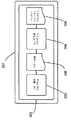
図1を参照すると、コンピュータ・システム101が、第2のコンピュータ103に接続された第1のコンピュータ102を含む。第1のコンピュータは、ネットワーク104を介して第3のコンピュータ105にも接続されている。本実施形態において、第1のコンピュータ102は、ウェブ・サーバ・アプリケーション・プログラムの形態の第1のコンピュータ・プログラム106を搭載しており、第2のコンピュータ103は、第2のコンピュータ・プログラム107を搭載している。本実施形態において、第1のコンピュータ・プログラム106は、第2のコンピュータ・プログラム107によって提供される機能を、第3のコンピュータ105のユーザが第3のコンピュータ105にインストールされたウェブ・ブラウザ・アプリケーション・プログラム108を通じてネットワーク104経由で利用できるようにするように構成される。言い換えると、第1のコンピュータ・プログラム106は、第2のコンピュータ・プログラム107のラッパとして構成される。
Referring to FIG. 1, a
本実施形態において、第2のコンピュータ・プログラム107は、第1のコンピュータ・プログラム106などのその他のアプリケーション・プログラムと通信するためのインターフェースなしで設計されたレガシー・アプリケーション・プログラムである。したがって、第1のコンピュータ・プログラム106は、第2のコンピュータ・プログラム107とインターフェースをとるためのインターフェース・プログラム109を与えられる。第2のコンピュータ・プログラム107は、関連するデータ処理ロジックと一体的にコーディングされ、したがって別々に再利用できない画面または表示ウィンドウなどのその第2のコンピュータ・プログラム107のデータ表現要素を用いて設計される。言い換えると、第2のコンピュータ・プログラム107の表示ロジックは、アプリケーション・ロジックに密接に関連して設けられる。インターフェース・プログラム109は、第1のコンピュータ・プログラム106が第2のコンピュータ・プログラム107の選択されたアプリケーション・ロジックを実行することを可能にするように、第2のコンピュータ・プログラム107の選択された表示画面を通じて第1のコンピュータ・プログラム106と第2のコンピュータ・プログラム107とのインターフェースをとるように構成される。
In this embodiment, the
本実施形態において、第2のコンピュータ103は、IBM(商標)AS/400コンピュータである。第2のコンピュータ・プログラム107は、IBM(商標)5250端末の形態の端末を介して使用するように元々設計されている。本実施形態において、インターフェース・プログラム109は、IBM(商標)社から入手可能なIBM(商標)Host on Demandライブラリを使用して、IBM(商標)5250端末を必要とせずにIBM(商標)AS/400コンピュータ上の第2のコンピュータ・プログラム107の表示ロジックに直接アクセスするように構成される。
In the present embodiment, the
図2を参照すると、第4のコンピュータ201が、Eclipse Foundation(商標),Inc.のEclipse(商標)SDEの形態のソフトウェア開発環境(SDE)プログラム202を搭載している。本実施形態において、SDE202は、フロー規定プログラム203およびコード生成プログラム204を提供するように構成される。フロー規定プログラム203は、ユーザが第2のコンピュータ・プログラム107の選択された処理フローを規定することを可能にするように構成される。本実施形態において、フロー規定プログラム203は、図4を参照して以下でさらに説明されるように、ユーザが選択された処理フローをグラフィカルに規定することを可能にするように構成される。そのようなユーザの規定に応じて、フロー規定プログラム203は、コード生成プログラム204への入力であるフロー定義205を出力する。コード生成プログラム204は、以下でさらに説明されるように、入力されたフロー定義205からインターフェース・プログラム109のためのコードを生成するように構成される。
Referring to FIG. 2, a
本実施形態において、第2のコンピュータ・プログラム107は、適切な端末の画面としてユーザに対して表示するために設計された1組の表示ウィンドウを含むユーザ・インターフェースを用いて構成される。表示ウィンドウは、入力フィールド、出力フィールドの形態の1つまたは複数のユーザ・インターフェース要素を含む可能性があり、所与の表示ウィンドウに関連する処理ロジックを実行するように第2のコンピュータ・プログラム107に命令するためのコマンドの形態の1つまたは複数のユーザ入力を受け付けるように構成される可能性がある。本実施形態において、インターフェース・プログラム109は、選択された機能が表示ウィンドウの関連するフローによって特定されるようにして、第2のコンピュータ・プログラム107の選択された機能または処理ロジックのフローとインターフェースをとるように構成される。図3は、第2のコンピュータ・プログラム107の選択されたデータ表示機能に関連する1組の表示ウィンドウ301、302、303の例を示す。選択されたデータ表示機能は、表示することができる利用可能なデータの範囲のメニューを提供する第1の表示ウィンドウ301によって開始される。第1の表示ウィンドウ301は、ユーザが、データの範囲、すなわち、AからMまでの範囲のデータ、またはNからZまでの範囲のデータを選択するためのコマンドを入力することを可能にする。そのようなコマンドに応答して、第2のコンピュータ・プログラム107は、第1の表示ウィンドウ301に戻る前に、選択されたデータの範囲に応じて表示ウィンドウのうちの第2のウィンドウ302または第3のウィンドウ303のどちらかに選択された範囲内の利用可能なデータを表示する。
In this embodiment, the
図4を参照すると、フロー規定プログラム203は、ユーザが、第2のコンピュータ・プログラム107の選択された処理ロジックを、関連する画面401、402、403、404、入力405、および出力406、407を特定するフロー定義205として規定することを可能にするように構成される。画面間の遷移408、409、410が規定され、データまたはコマンドが入力されるかまたはデータが出力される選択された処理内の点を表す。遷移408、409、410のそれぞれは、第2のコンピュータ・プログラム107によって処理される選択されたアプリケーション・ロジック・フローの対応する要素を表す。画面401、402、403、404のそれぞれは、それぞれの画面の一意識別子の働きをするそれぞれの画面種別(screen description)411、412、413、414を与えられる。一部の画面は、図4、および同じ画面種別「A」411、414を有する画面1および3 401、404の場合のように、所与の遷移において2回以上現れる可能性があるが、異なる結果を生じる可能性がある。図3から、表示ウィンドウのシーケンスはループと見なされる可能性があるが、処理ロジックの単一のフローの観点から見れば、画面1および3 401、404は、それぞれ、処理の開始点および終了点を表す。インターフェース・プログラム109は、以下でさらに説明されるように、画面種別を、第2のコンピュータ・プログラム107の処理中の任意の所与の時間に現在位置を特定するために使用する。本実施形態においては、上述のようにフロー定義205を生成するために、Eclipse Modelling Framework(EMF)が使用される。
Referring to FIG. 4, the
図5を参照すると、本実施形態において、コード生成プログラム204は、フロー定義205からインターフェース・プログラム109のためのJava(商標)のコードを生成するように構成される。図5は、生成されたJava(商標)のコードの機能要素を示す。当業者に理解されるであろうように、インターフェース・プログラム109は、第2のコンピュータ・プログラム107の1組の1つまたは複数の選択された処理ロジック・フローにインターフェースを提供するように構成され得る。本実施形態において、それぞれのそのような選択された処理ロジック・フローは、フロー処理クラス501およびデータ処理クラス502の形態の対応するインターフェース・ルーチンによってインターフェースをとられる。フロー処理クラス501は、インターフェース・プログラム109への入り口点(entry point)を提供し、第2のコンピュータ・プログラム107とのインターフェース動作を実行する。データ処理クラス502は、入力および出力405、406ならびにコマンド入力407のための必要なデータ構造を提供する。データ処理クラス502は、インターフェース・プログラム109と第1のコンピュータ・プログラム106との間のインターフェースを含む。フロー処理クラス501は、第2のコンピュータ・プログラム107の状態を特定するため、例えば、第2のコンピュータ・プログラム107が選択された機能を実行するためのその第2のコンピュータ・プログラム107の処理の開始点にいるときを判定するためにフロー処理クラス501によって使用される1組の予想される画面種別503を与えられる。
Referring to FIG. 5, in the present embodiment, the
フロー処理クラス501は、フロー定義205の画面401、402、403、404のそれぞれに対して1つずつ、1組の画面種別メソッド504および1組の画面識別子メソッド505をさらに含む。画面種別メソッド504は、それぞれの画面種別411、412、413、414を保持する。画面識別子メソッド505は、対応する画面種別メソッド504から得られた画面種別411、412、413、414を比較して、第2のコンピュータ・プログラム107の現在の画面を特定するように構成される。画面種別メソッド504および1組の画面識別子メソッド505は、予想される画面種別503などの1組の画面種別を入力し、もしあれば、特定された画面のうちのどれが第2のコンピュータ・プログラム107の現在の画面であるかを特定するように構成される画面チェッカー・メソッド506によって使用される。
The
フロー処理クラスは、フロー定義205の遷移408、409、410のそれぞれに対して1つずつ、1組の遷移メソッド507をさらに含む。各遷移メソッド507は、フロー定義205の所与の遷移に割り振られた入力、出力、またはコマンド508のいずれかのインターフェースをとるように構成される。したがって、遷移メソッド507は、データを、第2のコンピュータ・プログラム107の表示ウィンドウから、第1のコンピュータ・プログラム106に出力するためにデータ処理クラス502によって提供される対応するデータ構造に移すように構成され得る。同様に、遷移メソッド507は、データを、データ処理クラス502によって提供される関連するデータ構造から、第2のコンピュータ・プログラム107の表示ウィンドウの指定された入力フィールドに移すように構成され得る。遷移メソッド507は、所与の遷移に関連するレガシー・プログラムの処理を開始するために、シミュレーションされたキーの押下などのコマンドを第2のコンピュータ・プログラム107に入力するようにさらに構成され得る。
The flow processing class further includes a set of
さらに、各遷移メソッド507は、フロー定義205による所与の遷移に続くあり得る遷移先画面を特定する予想される画面の組509を与えられ、それぞれのそのようなあり得る遷移先画面に関連する適切な遷移メソッド507をやはり特定する。したがって、各遷移メソッド507は、入力、出力、またはコマンドの割り振られた処理が完了すると、予想される画面の組509のうちのどの画面が第2のコンピュータ・プログラム107によって指示されているかを特定するようにさらに構成される。このように新しい現在の画面が特定されると、遷移メソッド507は、フロー定義205で定義されたように、新しい現在の画面に対応する次の遷移メソッド507を呼び出すように構成される。要約すると、各遷移メソッド507は、以下の機能を実行するように構成される。
1.現在のレガシー・アプリケーションの表示ウィンドウからの任意の割り振られた出力からデータを読み出すこと。
2.現在のレガシー・アプリケーションの表示ウィンドウの任意の割り振られた入力にデータを書き込むこと。
3.現在の遷移の処理の結果として生じると予想される1組の表示ウィンドウを決定すること。
4.レガシー・アプリケーションにコマンドを与えることによって現在の遷移を実行すること。および
5.結果として生じる画面を特定し、対応する遷移メソッドを実行すること。
In addition, each
1. Reading data from any allocated output from the display window of the current legacy application.
2. Write data to any allocated input in the display window of the current legacy application.
3. Determining a set of display windows that are expected to result from processing the current transition.
4). Performing the current transition by giving a command to a legacy application. And 5. Identify the resulting screen and execute the corresponding transition method.
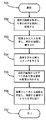
第1のコンピュータ・プログラム106からの、第2のコンピュータ・プログラム107によって提供される所定の選択された機能の要求に応答してインターフェース・プログラム109によって実行される処理が、以降、図6の流れ図を参照してさらに詳細に説明される。処理は、第1のコンピュータ・プログラム106からの要求に応答してステップ601で開始され、ステップ602に移る。ステップ602において、第1のコンピュータ・プログラム106による選択された処理ロジック・フローの要求に対応するインターフェースをとるルーチンが特定され、処理はステップ603に移る。ステップ603において、第2のコンピュータ・プログラム107との通信が、特定されたインターフェースをとるルーチンによって開始され、処理は、ステップ604に移る。ステップ604において、インターフェースをとるルーチンに対する最初の画面が待ち受けられ、与えられると、処理はステップ605に移る。ステップ605において、関連するインターフェース・データ構造から入力およびコマンドを取得し、関連するインターフェース・データ構造に出力を与える、インターフェースをとるルーチンに対して指定された遷移のシーケンスが、処理される。遷移のシーケンスの処理が完了すると、処理はステップ606に移り、終了する。
The process executed by the
所与の遷移メソッド507のインターフェース・プログラム109による処理が、以降、図7の流れ図を参照してさらに詳細に説明される。処理は、ステップ701において、フロー処理クラス501の入り口点からか、または別の遷移メソッド507によってかのいずれかで開始され、処理は、ステップ702に移る。ステップ702において、現在の画面の内容が、適切なHoD(商標)ライブラリ・ルーチンによって第2のコンピュータ・プログラム107から取得され、画面から任意の所定の出力、すなわち、フロー定義205で遷移に割り振られた任意の出力を抽出するために解析される。抽出された出力は、次に、第1のコンピュータ・プログラム106によるアクセスのために関連するデータ処理クラス502に記憶され、処理は、ステップ703に移る。ステップ703において、第2のコンピュータ・プログラム107に対する任意のデータ入力が、適切なHoD(商標)ライブラリ・ルーチンによって、関連するデータ処理クラス502から第2のコンピュータ・プログラム107の現在の画面に移され、処理は、ステップ704に移る。ステップ704において、第2のコンピュータ・プログラム107に対する任意のコマンド入力が、適切なHoD(商標)ライブラリ・ルーチンによって第2のコンピュータ・プログラム107に与えられ、処理は、ステップ705に移る。ステップ705において、現在の画面からのすべてのあり得る遷移先画面が、予想される画面の組509から特定され、処理は、ステップ706に移る。ステップ706において、第2のコンピュータ・プログラム107の出力が、適切なHoD(商標)ライブラリ・ルーチンによって問い合わされ、あり得る遷移先画面から新しい現在の画面が特定され、対応する遷移メソッド507が呼び出される。次に、処理は、ステップ707に進み、現在の遷移メソッド507に関して終了する。
The processing by the
フロー定義205からインターフェース・プログラム109を生成するためにコード生成プログラム204によって実行される処理が、以降、図8の流れ図を参照してさらに詳細に説明される。処理は、ステップ801で開始され、ステップ802に移り、ステップ802において、EMFの関連するフロー定義205が入力される。次に、処理はステップ803に移り、ステップ803において、インターフェース・プログラム109が、入力されたフロー定義205に対応するフロー・クラス(flow class)の形態のフロー処理クラス501によって初期化され、処理は、ステップ804に移る。ステップ804において、フロー定義205で定義された各入力および出力405、406、407に対応するデータ記憶要素を含むフロー入力/出力データ処理クラス502が生成され、処理はステップ805に移る。ステップ805において、フロー定義205の画面401、402、403、404のそれぞれに対する画面種別メソッド504および画面識別子メソッドを画面チェッカー・メソッド506とともに含む画面種別クラスが生成され、処理はステップ806に移る。ステップ806において、フロー定義205の各遷移408、409、410に対する遷移メソッド507が生成され、処理はステップ807に移る。ステップ807において、各遷移メソッド507が、対応する予想される画面の組509および対応する遷移メソッドによって補完される。次に、処理はステップ808に移り、ステップ808において、インターフェース・プログラム109が出力され、処理は終了する。
The process executed by the
インターフェース・プログラム109は、第2のコンピュータ・プログラム107の選択された1組のフロー定義205のそれぞれにアクセスできるようにするために複数のフロー処理クラス501を与えられる可能性がある。
The
別の実施形態においては、インターフェース・プログラムは、レガシー・プログラムの誤ったまたは予期せぬ振る舞いに対処し、例えば、そのレガシー・プログラムがインターフェースをとられているアプリケーション・プログラムにエラーを報告することによってそのような振る舞いを適切に処理するためのエラー処理機能が設けられる。 In another embodiment, the interface program addresses the incorrect or unexpected behavior of the legacy program, for example by reporting an error to the application program that the legacy program is interfaced with. An error handling function is provided to properly handle such behavior.
さらなる実施形態においては、フロー定義が、インターフェースをとられているプログラムのより複雑な処理ロジックの記述を容易にするためのサブルーチン、条件、またはループを含む可能性がある。 In further embodiments, the flow definition may include subroutines, conditions, or loops to facilitate the description of more complex processing logic of the interfaced program.
本発明の実施形態は、インターフェースをとられるプログラムの表現を用いて動作するためのインターフェース・コードを生成するように構成される。TN3270E、TN5250、VT100、VT220、VT420などのレガシー・システムを含むシステムのためのホスト・アクセス・メソッドをサポートするIBM Java Host−On−Demand(商標)などのホスト・アクセス・メソッド。それによって、インターフェース・コードは、レガシー・コンポーネントとインターフェースをとるためにその表現にぴったりとはまることによって、レガシーのロジックを最新のランタイム環境で提供する。 Embodiments of the present invention are configured to generate interface code for operation using a representation of an interfaced program. Host access methods such as IBM Java Host-On-Demand ™ that support host access methods for systems including legacy systems such as TN3270E, TN5250, VT100, VT220, VT420. Thereby, the interface code provides legacy logic in a modern runtime environment by fitting in its representation to interface with legacy components.
当業者に理解されるであろうように、上記の教示は、Java(商標)でのインターフェース・プログラムの生成に限定されず、任意の好適なソフトウェア言語で使用され得る。 As will be appreciated by those skilled in the art, the above teachings are not limited to generating interface programs in Java ™, but can be used in any suitable software language.
上述のフロー定義はグラフィカルに行われるが、選択されたアプリケーション・ロジック・フローが任意のその他の好適な手段で定義され得ることは、当業者に理解されるであろう。 Although the above flow definition is done graphically, those skilled in the art will appreciate that the selected application logic flow may be defined by any other suitable means.
上述のように、上述のインターフェース・プログラムは、特定のレガシー・システムにアクセスするために既存のHoD(商標)ライブラリ・ルーチンを利用する。当業者に理解されるであろうように、任意の好適なシステムに関してそのようなライブラリ・ルーチンが提供され得る。そのようなシステム・アクセス・ルーチンの機能は、インターフェースをとるプログラムの実施形態の機能の一部として提供され得る。さらに、任意のそのようなライブラリが、サード・パーティの提供者から得られるか、または特に所与のアプリケーション用に、つまり、カスタム開発によって開発される可能性がある。 As described above, the interface program described above utilizes existing HoD ™ library routines to access a specific legacy system. As will be appreciated by those skilled in the art, such library routines may be provided for any suitable system. The functionality of such system access routines can be provided as part of the functionality of the programmatic embodiment of the interface. In addition, any such library may be obtained from a third party provider or developed specifically for a given application, ie by custom development.
本発明の実施形態は、いわゆるレガシー・システムでの使用に限定されず、任意のコンピュータ・プログラムと、そのプログラムの選択された処理ロジックを駆動するためのそのプログラムの表示ウィンドウを通じてインターフェースをとるために提供され得る。 Embodiments of the present invention are not limited to use in so-called legacy systems, but to interface through any computer program and its display window for driving selected processing logic of that program. Can be provided.
本発明の実施形態は、レガシーのソフトウェア・コンポーネントがロジックと表現との間の堅い結びつきを含む、言い換えると、表現とロジックとが1つのコンポーネントでリンクされている場合に、レガシー・コンポーネントをサービス指向アーキテクチャ(SOA)などの最新のソフトウェア環境に統合するためのコードを生成するためのツールを提供する。 Embodiments of the present invention service a legacy component when the legacy software component includes a tight connection between logic and representation, in other words, when the representation and logic are linked by a single component. A tool is provided for generating code for integration into modern software environments such as architecture (SOA).
コンピュータ・プログラムは、使用されているソフトウェア言語と、そのようなソフトウェアが実行されるように意図されているシステムとに応じて、よくある補助的なソフトウェア要素および構造を含む。そのような要素および構造は、説明を明瞭にするために上記の説明に含まれていないが、当業者には明らかであろう。 Computer programs include common auxiliary software elements and structures, depending on the software language being used and the system on which such software is intended to be executed. Such elements and structures are not included in the above description for clarity of description, but will be apparent to those skilled in the art.
本発明の一部またはすべてを具現化する装置が、本発明の実施形態の一部またはすべてを提供するように構成されたソフトウェアを有する汎用デバイスである可能性があることは、当業者に理解されるであろう。デバイスは、単一のデバイスまたはデバイスのグループである可能性があり、ソフトウェアは、単一のプログラムまたは1組のプログラムである可能性がある。さらに、本発明を実装するために使用されるソフトウェアのいずれかまたはすべては、1つまたは複数のデバイスにロードされ得るように任意の好適な送信または記憶手段を介して伝達される可能性がある。 Those skilled in the art will appreciate that an apparatus embodying some or all of the present invention may be a general purpose device having software configured to provide some or all of the embodiments of the present invention. Will be done. A device can be a single device or a group of devices, and the software can be a single program or a set of programs. Further, any or all of the software used to implement the present invention may be communicated via any suitable transmission or storage means so that it can be loaded into one or more devices. .
本発明が本発明の実施形態の説明によって示され、実施形態が非常に詳細に説明されたが、出願人は、添付の特許請求の範囲をそのような詳細に制限するか、または何らかの形で限定することを意図していない。さらなる利点および改変が、当業者には容易に分かるであろう。したがって、本発明は、本発明のより広い態様において、代表的な装置および方法、ならびに図示され、説明された例示的な例の特定の詳細に限定されない。ゆえに、出願人の包括的な発明の概念の精神または範囲を逸脱することなく、そのような詳細から離れることができる。 While the invention has been shown by way of description of embodiments of the invention and the embodiments have been described in great detail, the applicant has limited the appended claims to such details or in some way It is not intended to be limiting. Additional advantages and modifications will be readily apparent to those skilled in the art. Accordingly, the invention in its broader aspects is not limited to the specific details of the exemplary apparatus and method and illustrative examples shown and described. Accordingly, departures may be made from such details without departing from the spirit or scope of applicants' general inventive concept.
Claims (8)
A)前記第2のコンピュータ・プログラムの選択されたアプリケーション・ロジック・フローに関連する第1の表示ウィンドウを特定するステップと、
B)前記第1のコンピュータ・プログラムに与えるための前記第1の表示ウィンドウからの1つまたは複数の表示ウィンドウの出力を割り振るステップと、
C)前記第2のコンピュータ・プログラムに与えるために前記第1の表示ウィンドウに入力するための1つまたは複数のデータ入力を割り振るステップと、
D)前記第1の表示ウィンドウに関連する前記選択されたアプリケーション・ロジック・フローを開始するために前記第1の表示ウィンドウに入力するための1つまたは複数の実行コマンドを割り振るステップと、
E)前記第1の表示ウィンドウ、ならびに前記関連する表示ウィンドウの出力、前記データ入力、および前記実行コマンドによって、前記選択されたアプリケーション・ロジック・フローに関して前記第1のコンピュータ・プログラムと前記第2のコンピュータ・プログラムとの間のインターフェースを提供するように構成され、
第1のコンピュータ・プログラムが、アプリケーション・ロジックが表示ロジックを通じて操作可能であるように前記アプリケーション・ロジックと密接に関連して前記表示ロジックを含む第2のコンピュータ・プログラムのアプリケーション・ロジックを実行することを可能にするための方法であって、
前記第2のコンピュータ・プログラムの選択されたアプリケーション・ロジック・フローに関連する所定の第1の表示ウィンドウを特定するステップと、
前記第2のコンピュータ・プログラムによる前記第1の表示ウィンドウの提供に応答して、
a)前記第1のコンピュータ・プログラムに提供するために前記第1の表示ウィンドウの任意の所定の出力からデータを読み出すステップと、
b)前記第2のコンピュータ・プログラムに入力するために前記第1の表示ウィンドウへの任意の所定の入力にデータを書き込むステップと、
c)前記第1の表示ウィンドウに関連する前記選択されたアプリケーション・ロジック・フローの処理を開始するために前記第2のコンピュータ・プログラムに任意の所定の実行コマンドを与えるステップと
を含む、方法を実行するように構成されるプログラム・インターフェース・コードを生成するステップと
を含む、方法。 A computer for interfacing with a first computer program and a second computer program including the display logic in close association with the application logic such that the application logic is operable through the display logic A method for generating program code, comprising:
A ) identifying a first display window associated with the selected application logic flow of the second computer program;
B ) allocating the output of one or more display windows from the first display window for providing to the first computer program;
C ) allocating one or more data inputs for input to the first display window for provision to the second computer program;
D ) allocating one or more execution commands for entering the first display window to initiate the selected application logic flow associated with the first display window;
E ) The first computer program and the second display window with respect to the selected application logic flow by the first display window and the output of the associated display window, the data input, and the execute command. Configured to provide an interface to a computer program;
A first computer program executing application logic of a second computer program including the display logic in close association with the application logic such that the application logic is operable through the display logic; A method for enabling
Identifying a predetermined first display window associated with a selected application logic flow of the second computer program;
In response to providing the first display window by the second computer program,
a) reading data from any predetermined output of the first display window for provision to the first computer program;
b) writing data to any given input to the first display window for input to the second computer program;
c) providing any predetermined execution command to the second computer program to initiate processing of the selected application logic flow associated with the first display window. Generating program interface code configured to execute.
それぞれの第2の表示ウィンドウに関して前記ステップB)、C)、およびD)を実行するステップと、
前記第1の表示ウィンドウおよび前記第2の表示ウィンドウ、ならびに前記関連する表示ウィンドウの出力、前記データ入力、および前記実行コマンドによって、前記選択されたアプリケーション・ロジック・フローに関して前記第1のコンピュータ・プログラムと前記第2のコンピュータ・プログラムとの間のインターフェースを提供するように構成され、
第1のコンピュータ・プログラムが、アプリケーション・ロジックが表示ロジックを通じて操作可能であるように前記アプリケーション・ロジックと密接に関連して前記表示ロジックを含む第2のコンピュータ・プログラムのアプリケーション・ロジックを実行することを可能にするための方法であって、
前記第2のコンピュータ・プログラムの選択されたアプリケーション・ロジック・フローに関連する所定の第1の表示ウィンドウを特定するステップと、
前記第2のコンピュータ・プログラムによる前記第1の表示ウィンドウの提供に応答して、
a)前記第1のコンピュータ・プログラムに提供するために前記第1の表示ウィンドウの任意の所定の出力からデータを読み出すステップと、
b)前記第2のコンピュータ・プログラムに入力するために前記第1の表示ウィンドウへの任意の所定の入力にデータを書き込むステップと、
c)前記第1の表示ウィンドウに関連する前記選択されたアプリケーション・ロジック・フローの処理を開始するために前記第2のコンピュータ・プログラムに任意の所定の実行コマンドを与えるステップと
を含む、方法を実行するように構成される前記プログラム・インターフェース・コードを生成するステップと
をさらに含む、請求項1に記載の方法。 A predetermined set of one or more second from the second computer program that may be provided immediately after the first display window in response to the processing of the selected application logic flow. Identifying the display window;
Performing said steps B ), C ), and D ) for each second display window;
The first computer program with respect to the selected application logic flow by the first display window and the second display window, and the output of the associated display window, the data input, and the execute command And an interface between the second computer program and the second computer program,
A first computer program executing application logic of a second computer program including the display logic in close association with the application logic such that the application logic is operable through the display logic; A method for enabling
Identifying a predetermined first display window associated with a selected application logic flow of the second computer program;
In response to providing the first display window by the second computer program,
a) reading data from any predetermined output of the first display window for provision to the first computer program;
b) writing data to any given input to the first display window for input to the second computer program;
c) providing any predetermined execution command to the second computer program to initiate processing of the selected application logic flow associated with the first display window. Generating the program interface code configured to execute. The method of claim 1, further comprising:
A)前記第2のコンピュータ・プログラムの選択されたアプリケーション・ロジック・フローに関連する第1の表示ウィンドウを特定し、
B)前記第1のコンピュータ・プログラムに与えるための前記第1の表示ウィンドウからの1つまたは複数の表示ウィンドウの出力を割り振り、
C)前記第2のコンピュータ・プログラムに与えるために前記第1の表示ウィンドウに入力するための1つまたは複数のデータ入力を割り振り、
D)前記第1の表示ウィンドウに関連する前記選択されたアプリケーション・ロジック・フローを開始するために前記第1の表示ウィンドウに入力するための1つまたは複数の実行コマンドを割り振り、
E)前記第1の表示ウィンドウ、ならびに前記関連する表示ウィンドウの出力、前記データ入力、および前記実行コマンドによって、前記選択されたアプリケーション・ロジック・フローに関して前記第1のコンピュータ・プログラムと前記第2のコンピュータ・プログラムとの間のインターフェースを提供するように構成され、
第1のコンピュータ・プログラムが、アプリケーション・ロジックが表示ロジックを通じて操作可能であるように前記アプリケーション・ロジックと密接に関連して前記表示ロジックを含む第2のコンピュータ・プログラムのアプリケーション・ロジックを実行することを可能にするための装置であって、
前記第2のコンピュータ・プログラムの選択されたアプリケーション・ロジック・フローに関連する所定の第1の表示ウィンドウを特定し、
前記第2のコンピュータ・プログラムによる前記第1の表示ウィンドウの提供に応答して、
a)前記第1のコンピュータ・プログラムに提供するために前記第1の表示ウィンドウの任意の所定の出力からデータを読み出し、
b)前記第2のコンピュータ・プログラムに入力するために前記第1の表示ウィンドウへの任意の所定の入力にデータを書き込み、
c)前記第1の表示ウィンドウに関連する前記選択されたアプリケーション・ロジック・フローの処理を開始するために前記第2のコンピュータ・プログラムに任意の所定の実行コマンドを与える
ように動作可能である、装置をもたらすように構成されるプログラム・インターフェース・コードを生成する
ように動作可能である、装置。 A computer for interfacing with a first computer program and a second computer program including the display logic in close association with the application logic such that the application logic is operable through the display logic An apparatus for generating program code,
A ) identifying a first display window associated with the selected application logic flow of the second computer program;
B ) Allocating the output of one or more display windows from the first display window for providing to the first computer program;
C ) allocate one or more data inputs for input to the first display window for provision to the second computer program;
D ) Allocate one or more execution commands to enter the first display window to initiate the selected application logic flow associated with the first display window;
E ) The first computer program and the second display window with respect to the selected application logic flow by the first display window and the output of the associated display window, the data input, and the execute command. Configured to provide an interface to a computer program;
A first computer program executing application logic of a second computer program including the display logic in close association with the application logic such that the application logic is operable through the display logic; A device for enabling
Identifying a predetermined first display window associated with the selected application logic flow of the second computer program;
In response to providing the first display window by the second computer program,
a) reading data from any given output of the first display window for provision to the first computer program;
b) write data to any given input to the first display window for input to the second computer program;
c) operable to provide any predetermined execution command to the second computer program to initiate processing of the selected application logic flow associated with the first display window; A device that is operable to generate program interface code configured to yield a device.
それぞれの第2の表示ウィンドウに関して動作B)、C)、およびD)を実行し、
前記第1の表示ウィンドウおよび前記第2の表示ウィンドウ、ならびに前記関連する表示ウィンドウの出力、前記データ入力、および前記実行コマンドによって、前記選択されたアプリケーション・ロジック・フローに関して前記第1のコンピュータ・プログラムと前記第2のコンピュータ・プログラムとの間のインターフェースを提供するように構成され、
第1のコンピュータ・プログラムが、アプリケーション・ロジックが表示ロジックを通じて操作可能であるように前記アプリケーション・ロジックと密接に関連して前記表示ロジックを含む第2のコンピュータ・プログラムのアプリケーション・ロジックを実行することを可能にするための装置であって、
前記第2のコンピュータ・プログラムの選択されたアプリケーション・ロジック・フローに関連する所定の第1の表示ウィンドウを特定し、
前記第2のコンピュータ・プログラムによる前記第1の表示ウィンドウの提供に応答して、
a)前記第1のコンピュータ・プログラムに提供するために前記第1の表示ウィンドウの任意の所定の出力からデータを読み出し、
b)前記第2のコンピュータ・プログラムに入力するために前記第1の表示ウィンドウへの任意の所定の入力にデータを書き込み、
c)前記第1の表示ウィンドウに関連する前記選択されたアプリケーション・ロジック・フローの処理を開始するために前記第2のコンピュータ・プログラムに任意の所定の実行コマンドを与える
ように動作可能である、装置をもたらすように構成される前記プログラム・インターフェース・コードを生成する
ようにさらに動作可能である、請求項5に記載の装置。 A predetermined set of one or more second from the second computer program that may be provided immediately after the first display window in response to the processing of the selected application logic flow. Identify the display window,
Perform operations B ), C ), and D ) for each second display window;
The first computer program with respect to the selected application logic flow by the first display window and the second display window, and the output of the associated display window, the data input, and the execute command And an interface between the second computer program and the second computer program,
A first computer program executing application logic of a second computer program including the display logic in close association with the application logic such that the application logic is operable through the display logic; A device for enabling
Identifying a predetermined first display window associated with the selected application logic flow of the second computer program;
In response to providing the first display window by the second computer program,
a) reading data from any given output of the first display window for provision to the first computer program;
b) write data to any given input to the first display window for input to the second computer program;
c) operable to provide any predetermined execution command to the second computer program to initiate processing of the selected application logic flow associated with the first display window; The apparatus of claim 5, further operable to generate the program interface code configured to provide an apparatus.
Applications Claiming Priority (3)
| Application Number | Priority Date | Filing Date | Title |
|---|---|---|---|
| EP11185994.8 | 2011-10-20 | ||
| EP11185994 | 2011-10-20 | ||
| PCT/IB2012/054962 WO2013057607A1 (en) | 2011-10-20 | 2012-09-19 | Computer program interface |
Publications (2)
| Publication Number | Publication Date |
|---|---|
| JP2014532223A JP2014532223A (en) | 2014-12-04 |
| JP5657183B2 true JP5657183B2 (en) | 2015-01-21 |
Family
ID=48140416
Family Applications (1)
| Application Number | Title | Priority Date | Filing Date |
|---|---|---|---|
| JP2014532519A Active JP5657183B2 (en) | 2011-10-20 | 2012-09-19 | Method and apparatus for enabling a first computer program to execute application logic of a second computer program, for interfacing the first computer program and the second computer program And apparatus for generating computer program code for the same, a computer program, and a software interface for enabling a first computer program to execute application logic of a second computer program For providing information (computer program interface) |
Country Status (4)
| Country | Link |
|---|---|
| US (1) | US10545729B2 (en) |
| JP (1) | JP5657183B2 (en) |
| CN (1) | CN103890721B (en) |
| WO (1) | WO2013057607A1 (en) |
Families Citing this family (2)
| Publication number | Priority date | Publication date | Assignee | Title |
|---|---|---|---|---|
| EP3405865A1 (en) * | 2016-01-21 | 2018-11-28 | Playgiga S.L. | Modification of software behavior in run time |
| US11481233B2 (en) * | 2019-09-13 | 2022-10-25 | Logistiview, Inc. | Augmenting legacy user interfaces using workflows |
Family Cites Families (12)
| Publication number | Priority date | Publication date | Assignee | Title |
|---|---|---|---|---|
| JP2002091780A (en) * | 2000-09-12 | 2002-03-29 | Nec Corp | System and method for processing transaction |
| JP2002334058A (en) * | 2001-05-10 | 2002-11-22 | Beacon Information Technology:Kk | Method and system for executing application of mainframe and program |
| CA2348706A1 (en) | 2001-05-25 | 2002-11-25 | Ibm Canada Limited-Ibm Canada Limitee | Converting user interface source code of a legacy application to web pages |
| JP2003114874A (en) * | 2001-10-09 | 2003-04-18 | Canon Software Inc | Web server device, method of controlling web server device, program, and recording medium |
| US7099447B2 (en) * | 2002-04-08 | 2006-08-29 | Sbc Services, Inc. | System and method for modifying package service subscriptions online |
| US7665064B2 (en) * | 2004-05-14 | 2010-02-16 | Gt Software, Inc. | Systems and methods for web service function, definition, implementation, and/or execution |
| KR100616157B1 (en) * | 2005-01-11 | 2006-08-28 | 와이더댄 주식회사 | Method and syetem for interworking plurality of applications |
| WO2007122640A2 (en) | 2006-04-26 | 2007-11-01 | Tata Consultancy Services | A system and method for automated re-architectureing of legacy systems using object-oriented language |
| KR100910336B1 (en) | 2006-10-19 | 2009-07-31 | 신동혁 | A system and method for managing the business process model which mapped the logical process and the physical process model |
| GB0622063D0 (en) | 2006-11-06 | 2006-12-13 | Standard Life Employee Service | Improvements in and relating to financial systems |
| US7792853B2 (en) | 2006-11-08 | 2010-09-07 | Ragothaman Subbian | Presenting data flow in legacy program |
| US20080270153A1 (en) | 2007-04-30 | 2008-10-30 | International Business Machines Corporation | Service oriented architecture (soa) lifecycle model migration |
-
2012
- 2012-09-19 JP JP2014532519A patent/JP5657183B2/en active Active
- 2012-09-19 CN CN201280050017.7A patent/CN103890721B/en active Active
- 2012-09-19 WO PCT/IB2012/054962 patent/WO2013057607A1/en active Application Filing
- 2012-10-22 US US13/657,099 patent/US10545729B2/en not_active Expired - Fee Related
Also Published As
| Publication number | Publication date |
|---|---|
| JP2014532223A (en) | 2014-12-04 |
| US20130117728A1 (en) | 2013-05-09 |
| CN103890721B (en) | 2017-07-07 |
| WO2013057607A1 (en) | 2013-04-25 |
| US10545729B2 (en) | 2020-01-28 |
| CN103890721A (en) | 2014-06-25 |
Similar Documents
| Publication | Publication Date | Title |
|---|---|---|
| US8875098B2 (en) | Workflow engine for execution of web mashups | |
| KR101645052B1 (en) | Debugging pipeline | |
| CN108351764B (en) | Data processing method and system | |
| NL2010546C2 (en) | Method and apparatus for automatically generating a test script for a graphical user interface. | |
| US8201143B2 (en) | Dynamic mating of a modified user interface with pre-modified user interface code library | |
| US7992128B2 (en) | Computer software adaptation method and system | |
| CN108427642A (en) | The method and apparatus of components testing in a kind of interface | |
| EP2697715A1 (en) | System and method for mobile application development | |
| JPH09259153A (en) | Device and method for generating batch execution control program | |
| US7730495B2 (en) | Declaratively defined control actions | |
| US20110126171A1 (en) | Dynamic native editor code view facade | |
| JP5657183B2 (en) | Method and apparatus for enabling a first computer program to execute application logic of a second computer program, for interfacing the first computer program and the second computer program And apparatus for generating computer program code for the same, a computer program, and a software interface for enabling a first computer program to execute application logic of a second computer program For providing information (computer program interface) | |
| US10606569B2 (en) | Declarative configuration elements | |
| JP4735854B2 (en) | PLC program development support device | |
| US9298428B2 (en) | Graphical user interface editor that displays live data during editing | |
| US10203939B2 (en) | Method and system for parameter model framework | |
| JP5540856B2 (en) | Apparatus and method for setting a workflow | |
| CN111782196A (en) | MVP architecture-based development method and device | |
| US20240086182A1 (en) | Method for connecting a web socket session with an object instance with automation device association | |
| JP2010204840A (en) | Customization method, terminal apparatus, computer program, and information recording medium for user interface operation integration system | |
| JP5645325B2 (en) | User interface operation integration system customization method, terminal device, computer program, and information recording medium | |
| Wu et al. | Using MFC and Managed C++ to Realize Configuration Utility | |
| CN112764721A (en) | Data processing method, device, system and computer readable storage medium | |
| JP2012022425A (en) | Device and method for automatically generating program and program | |
| CN111052071A (en) | Software introduction system, software introduction method, and software introduction program |
Legal Events
| Date | Code | Title | Description |
|---|---|---|---|
| A131 | Notification of reasons for refusal |
Free format text: JAPANESE INTERMEDIATE CODE: A131 Effective date: 20140902 |
|
| A521 | Request for written amendment filed |
Free format text: JAPANESE INTERMEDIATE CODE: A523 Effective date: 20141021 |
|
| TRDD | Decision of grant or rejection written | ||
| A01 | Written decision to grant a patent or to grant a registration (utility model) |
Free format text: JAPANESE INTERMEDIATE CODE: A01 Effective date: 20141104 |
|
| A61 | First payment of annual fees (during grant procedure) |
Free format text: JAPANESE INTERMEDIATE CODE: A61 Effective date: 20141125 |
|
| R150 | Certificate of patent or registration of utility model |
Ref document number: 5657183 Country of ref document: JP Free format text: JAPANESE INTERMEDIATE CODE: R150 |