JP5655152B2 - Polar borehole - Google Patents
Polar borehole Download PDFInfo
- Publication number
- JP5655152B2 JP5655152B2 JP2013536486A JP2013536486A JP5655152B2 JP 5655152 B2 JP5655152 B2 JP 5655152B2 JP 2013536486 A JP2013536486 A JP 2013536486A JP 2013536486 A JP2013536486 A JP 2013536486A JP 5655152 B2 JP5655152 B2 JP 5655152B2
- Authority
- JP
- Japan
- Prior art keywords
- side wall
- drilling
- drill floor
- polar
- borehole
- Prior art date
- Legal status (The legal status is an assumption and is not a legal conclusion. Google has not performed a legal analysis and makes no representation as to the accuracy of the status listed.)
- Expired - Fee Related
Links
- 238000005553 drilling Methods 0.000 claims description 37
- 230000003014 reinforcing effect Effects 0.000 claims description 9
- 230000002787 reinforcement Effects 0.000 claims description 4
- PEDCQBHIVMGVHV-UHFFFAOYSA-N Glycerine Chemical compound OCC(O)CO PEDCQBHIVMGVHV-UHFFFAOYSA-N 0.000 description 6
- 230000000903 blocking effect Effects 0.000 description 2
- VNWKTOKETHGBQD-UHFFFAOYSA-N methane Chemical compound C VNWKTOKETHGBQD-UHFFFAOYSA-N 0.000 description 2
- 238000003466 welding Methods 0.000 description 2
- 239000010779 crude oil Substances 0.000 description 1
- 230000000694 effects Effects 0.000 description 1
- 238000005516 engineering process Methods 0.000 description 1
- 230000007613 environmental effect Effects 0.000 description 1
- 239000007789 gas Substances 0.000 description 1
- 230000002452 interceptive effect Effects 0.000 description 1
- 238000004519 manufacturing process Methods 0.000 description 1
- 238000005065 mining Methods 0.000 description 1
- 239000003345 natural gas Substances 0.000 description 1
- 230000000414 obstructive effect Effects 0.000 description 1
- 239000003921 oil Substances 0.000 description 1
- 239000012779 reinforcing material Substances 0.000 description 1
- XLYOFNOQVPJJNP-UHFFFAOYSA-N water Substances O XLYOFNOQVPJJNP-UHFFFAOYSA-N 0.000 description 1
Images

Classifications
-
- B—PERFORMING OPERATIONS; TRANSPORTING
- B63—SHIPS OR OTHER WATERBORNE VESSELS; RELATED EQUIPMENT
- B63B—SHIPS OR OTHER WATERBORNE VESSELS; EQUIPMENT FOR SHIPPING
- B63B35/00—Vessels or similar floating structures specially adapted for specific purposes and not otherwise provided for
- B63B35/44—Floating buildings, stores, drilling platforms, or workshops, e.g. carrying water-oil separating devices
- B63B35/4413—Floating drilling platforms, e.g. carrying water-oil separating devices
Landscapes
- Engineering & Computer Science (AREA)
- Architecture (AREA)
- Civil Engineering (AREA)
- Structural Engineering (AREA)
- Chemical & Material Sciences (AREA)
- Combustion & Propulsion (AREA)
- Mechanical Engineering (AREA)
- Ocean & Marine Engineering (AREA)
- Earth Drilling (AREA)
- Working Measures On Existing Buildindgs (AREA)
- Signal Processing For Digital Recording And Reproducing (AREA)
- Eye Examination Apparatus (AREA)
Description
本発明は、極地用試錐船に関し、より詳細には、極地での試錐作業に対する外気の影響を最小化するためのウェザータイト(weather tight)構造を経済的且つ容易に設けることができるようにし、試錐作業区域において邪魔になる構造物を最小化するように構成された極地用試錐船に関する。 The present invention relates to a polar borehole, and more particularly, to enable economical and easy provision of a weather tight structure for minimizing the effect of outside air on polar borehole operations, TECHNICAL FIELD The present invention relates to a polar borehole configured to minimize structures that are obstructive in a borehole work area.
一般的に、試錐船は、原油やガスなどの海洋地下資源を探査して試錐する船舶を称するものであり、固定式プラットホーム、半潜水式試錐船、ドリルシップなどがある。 Generally, a borehole refers to a vessel that explores an underground underground resource such as crude oil or gas, and includes a fixed platform, a semi-submersible borehole, and a drillship.
このような試錐船は、海底面に埋め込まれている石油や天然ガスの探査及び採掘に要される技術の急速な発展により、水深200m程度の大陸棚のような浅い海域から、2,000m以上の深海や極地のような劣悪な環境の地域にまで、作業海域が拡大している。 Such drills are more than 2,000m from shallow sea areas such as continental shelves with a water depth of about 200m due to the rapid development of technology required for exploration and mining of oil and natural gas embedded in the ocean floor. The work area has been extended to areas of poor environment such as the deep sea and polar regions.
図1は従来の技術による試錐船を図示した横断面図である。図1に図示されたように、従来の技術による試錐船10は、船体11のデッキ(deck)上にドリルフロア(drill floor)12が設けられ、ビーム(beam)及び各種試錐装備で構成されている複雑な形態の大型構造物であるデリック(derrick)13がドリルフロア12に固定され、試錐装備の装着のために試錐井(drill well)のような大規模のムーンプール(moon pool)14が船体11に形成される。
FIG. 1 is a cross-sectional view illustrating a conventional drilling vessel. As shown in FIG. 1, a conventional drilling vessel 10 is provided with a drill floor 12 on a deck of a hull 11 and includes a beam and various types of drilling equipment. The
このような従来の試錐船は、極地で作業する場合、外気の温度によって試錐装備及び作業空間が低温の外気に露出され試錐作業が困難になるため、試錐装備及び作業空間を外気の露出から遮断しなければならない。 In such a conventional drilling vessel, when working in the polar region, the drilling equipment and work space are exposed to low temperature outside air due to the temperature of the outside air, making the drilling work difficult. Must.
しかし、試錐船の場合、主要な試錐装備がリグフロア(rig floor)、最上甲板、及びムーンプールの区域に広範囲に配置されるため、既存のドリルシップの船体タイプに船殻化構造物で試錐作業区域を遮断するように製作することが困難であるだけでなく、非経済的である。また、試錐の運用特性を考慮すると、運用時に干渉の危険がある構造が所々に配置されることを避けることができないという問題点を有していた。 However, in the case of a drilling vessel, the main drilling equipment is extensively located on the rig floor, top deck, and moon pool area, so that the drilling work can be carried out with the hulled structure of the existing drillship hull type. Not only is it difficult to fabricate to block the area, it is also uneconomical. In addition, when considering the operational characteristics of the borehole, there is a problem in that it is unavoidable that there are places where there is a risk of interference during operation.
本発明は、上記のような従来の問題点を解決するためのものであり、船側外板地点または船側外板に近い地点から最上甲板の上部に、一つのコンパートメント(compartment)の概念で、ウェザータイト(weather tight)構造物を形成することにより、極地での試錐作業における外気による影響を最小化し、試錐作業区域において邪魔になる構造物を最小化することを目的とする。 The present invention is intended to solve the above-described conventional problems, and it is a weather concept in the concept of a single compartment from a ship side skin plate point or a point close to the ship side skin plate to the upper part of the top deck. The object is to minimize the influence of outside air in the drilling work in the polar region by forming a tighter structure, and to minimize the structure that becomes an obstacle in the drilling work area.
前記目的を果たすための本発明の一側面によると、極地で運用可能な試錐船であって、ドリルフロア及び試錐作業区域を外気から保護するために、ウェザータイト構造物の左側壁及び右側壁は試錐作業区域を中心に船側外板に連結され、前記ウェザータイト構造物の前側壁及び後側壁は前記試錐作業区域の前後側で最上甲板に連結され、前記ウェザータイト構造物に加えられるドリリングの運用荷重に対する補強のために設けられる補強部が、前記左側壁、右側壁、前側壁及び後側壁に連結されていることを特徴とする極地用試錐船が提供される。 According to one aspect of the present invention for achieving the above object, the left and right side walls of the weathertight structure are a drilling vessel that can be operated in a polar region and protect the drill floor and the drilling work area from outside air. The drilling operation is connected to the ship side skin centering around the drilling work area, and the front and rear side walls of the weathertight structure are connected to the uppermost deck on the front and rear sides of the drilling work area and added to the weathertight structure. There is provided a polar borehole characterized in that a reinforcing portion provided for reinforcement against a load is connected to the left side wall, the right side wall, the front side wall, and the rear side wall.
前記ウェザータイト構造物の補強部は格子桁構造を有することが好ましい。 It is preferable that the reinforcing part of the weather tight structure has a lattice beam structure.
前記補強部は前記ドリルフロアの下部構造を形成することが好ましい。 The reinforcing part preferably forms a lower structure of the drill floor.
前記ドリルフロアは、両側が船体の幅に対応する位置まで延長して形成されることが好ましい。 The drill floor is preferably formed so that both sides extend to a position corresponding to the width of the hull.
前記左側壁及び右側壁の下端は、前記船側外板と同一平面を成すように互いに連結されることが好ましい。 It is preferable that lower ends of the left side wall and the right side wall are connected to each other so as to be flush with the ship side skin.
本発明によると、極地での試錐作業に対する外気の影響を最小化するためのウェザータイト(weather tight)構造を経済的且つ容易に製作することができる。また、船側外板のみで船体縦強度部材及びウェザータイト構造物を効率的に支持することにより、試錐作業区域において邪魔になる構造物を最小化し、極地での試錐作業空間に対する構造補強材を別に設ける必要がないだけでなく、極地での試錐作業空間の確保に効果的であり、ムーンプールの上部区域の空間制約を解決することができる。 According to the present invention, it is possible to economically and easily manufacture a weather tight structure for minimizing the influence of outside air on a drilling operation in a polar region. In addition, by efficiently supporting the hull longitudinal strength members and weathertight structures only by the ship side skin, the structure that becomes an obstacle in the borehole work area is minimized, and the structural reinforcement for the borehole work space in the polar region is separated. Not only does it need to be provided, it is also effective in securing a drilling work space in the polar region, and can solve the space constraints in the upper area of the moon pool.
また、本発明によると、船側外板と連結された上部構造は、ウェザータイト構造の前側壁及び後側壁とともに格子桁構造(Grillage Girder System)を形成することができるため、上部構造(例えば、ドリルフロア)に加えられるドリリングの運用荷重に対する補強が可能である。 In addition, according to the present invention, the upper structure connected to the ship side skin can form a grid girder structure together with the front side wall and the rear side wall of the weathertight structure. It is possible to reinforce the operational load of drilling applied to the floor.
以下、添付図面を参照して本発明の好ましい実施例に係る構成及び作用を詳細に説明すると次のとおりである。また、下記実施例は、様々な他の形態に変形されることができ、本発明の範囲が下記実施例に限定されるものではない。 Hereinafter, a configuration and an operation according to a preferred embodiment of the present invention will be described in detail with reference to the accompanying drawings. The following examples can be modified in various other forms, and the scope of the present invention is not limited to the following examples.
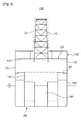
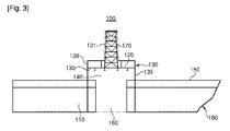
図2は本発明による極地用試錐船を図示した横断面図であり、図3は本発明による極地用試錐船を図示した縦断面図である。 FIG. 2 is a cross-sectional view illustrating a polar borehole according to the present invention, and FIG. 3 is a longitudinal cross-sectional view illustrating a polar borehole according to the present invention.
図2及び図3に図示されたように、本発明による極地用試錐船100は、極地で運用可能な試錐船であり、ドリルフロア(drill floor)120及び試錐作業区域140を外気から保護するウェザータイト構造物(weather tight structure)130が試錐作業区域140を中心に船側外板110に連結される。
As shown in FIGS. 2 and 3, the
ウェザータイト構造物130は、ドリルフロア120及び試錐作業区域140を外気から保護するために、ドリルフロア120及び試錐作業区域140を包むように製作される。図2に図示されたように、ウェザータイト構造物130の左右側には、下方に延長して船側外板110に連結されるための連結部、即ち、左右側壁132が形成され、図3に図示されたように、ウェザータイト構造物130の前後側には前側壁135及び後側壁136が形成される。
The
左右側壁132の下端は、例えば熔接や別の締結部材により、船側外板110と略同一平面を成すように互いに連結されることができる。一方、前側壁135及び後側壁136の下端は、例えば熔接や別の締結部材により、最上甲板150上に互いに連結されることができる。図3には、前側壁135及び後側壁136の下端が最上甲板150と直角を成すように図示されているが、前側壁135と後側壁136のうち少なくとも一つは最上甲板150に傾斜するように連結されることができることはいうまでもない。
The lower ends of the left and
従って、ウェザータイト構造物130は、ムーンプール(moon pool)160からドリルフロア120に至る区域を外気から遮断するだけでなく、船体180に容易に設けられることができる。
Accordingly, the
ドリルフロア120の上にはデリック(derrick)170が固定され、試錐作業区域140の確保、試錐作業区域140に干渉を起こす構造物の最小化、及びウェザータイト構造物130の安定した支持のために、ドリルフロア120の両側が船体180の幅に対応する位置まで延長して形成されることができる。これにより、ウェザータイト構造物130も船体180の幅と相応する幅を有するようになる。
A derrick 170 is fixed on the
ウェザータイト構造物130は、デリック170などの荷重を安定して支持するために、格子桁構造(grillage girder system)を有する補強部133を備えることができる。ここで、補強部133は、例えばドリルフロア120の下部構造を成すことができ、左右側壁132と前後側壁135、136(即ち、ウェザータイト構造物130の長さ方向の両端構造)とによって製作されることができる。これにより、ウェザータイト構造物130に加えられるドリリングの運用荷重に対する補強を可能にする。
The
また、ウェザータイト構造物130は、上方に突出するデリック170を包むための遮断部131を備えることができる。これにより、デリック170を介する外気の出入りを遮断することができる。
In addition, the weather
このような本発明による極地用試錐船の作用について説明する。 The operation of the polar borehole according to the present invention will be described.
本発明によると、ドリルフロア120及び試錐作業区域140を包むウェザータイト構造物130が船側外板110に連結されることにより、船体縦強度部材及びウェザータイト構造物130が容易に設けられることができる。これにより、ウェザータイト構造物130によってムーンプール160からドリルフロア120に至る全区域を外気から保護することができる。
According to the present invention, the weather
また、ウェザータイト構造物130の左右側壁132は船側外板110に連結され、ウェザータイト構造物130の前後側壁135、136は最上甲板150に連結されるため、格子桁構造を形成して、ウェザータイト構造物130の上部に加えられるドリリングの運用荷重に対する補強が可能になる。さらに、ウェザータイト構造物130の設置にかかる時間及びコストを減らすことができ、ウェザータイト構造物130の補強構造が試錐作業の運用に邪魔にならないようにすることができ、ウェザータイト構造物130の補強部133によって試錐作業時に発生する可能性のある運用荷重及び環境荷重に耐えるようにする。これにより、極地での試錐作業空間に対する別の構造補強材を設ける必要がないだけでなく、極地での試錐作業空間を効果的に確保することができ、ムーンプール160の上部区域の空間が制約されてしまうことを防止する。
In addition, the left and
Claims (2)
ドリルフロアの上にデリックが固定され、
前記ドリルフロア及び試錐作業区域を外気から保護するために、ウェザータイト構造物の左側壁及び右側壁は試錐作業区域を中心に船側外板と同一平面を成すように連結され、
前記ウェザータイト構造物の前側壁及び後側壁は前記試錐作業区域の前後側で最上甲板に連結され、
前記ウェザータイト構造物に加えられるドリリングの運用荷重に対する補強のために設けられる補強部が、前記左側壁、右側壁、前側壁及び後側壁に連結され、
前記補強部は前記ドリルフロアの下部構造を形成し、
前記ドリルフロアは、両側が船体の幅に対応する位置まで延長して形成され、前記デリックの荷重が前記船側外板にかかることを特徴とする極地用試錐船。 A drilling vessel that can be operated in polar regions,
The derrick is fixed on the drill floor,
In order to protect the drill floor and the drilling work area from the outside air, the left side wall and the right side wall of the weathertight structure are connected so as to be flush with the ship side skin plate around the drilling work area,
The front and rear side walls of the weathertight structure are connected to the uppermost deck on the front and rear sides of the borehole work area,
Reinforcing portions provided for reinforcement against the operational load of drilling applied to the weathertight structure are connected to the left side wall, right side wall, front side wall and rear side wall,
The reinforcing portion forms a lower structure of the drill floor,
The drill floor for a polar region, wherein both sides of the drill floor are extended to a position corresponding to the width of the hull, and the load of the derrick is applied to the outer shell plate .
Applications Claiming Priority (3)
| Application Number | Priority Date | Filing Date | Title |
|---|---|---|---|
| KR10-2010-0107702 | 2010-11-01 | ||
| KR1020100107702A KR20120045858A (en) | 2010-11-01 | 2010-11-01 | Drill ship for polar region |
| PCT/KR2011/004691 WO2012060531A1 (en) | 2010-11-01 | 2011-06-28 | Drilling ship for a polar region |
Publications (2)
| Publication Number | Publication Date |
|---|---|
| JP2013540646A JP2013540646A (en) | 2013-11-07 |
| JP5655152B2 true JP5655152B2 (en) | 2015-01-14 |
Family
ID=46024631
Family Applications (1)
| Application Number | Title | Priority Date | Filing Date |
|---|---|---|---|
| JP2013536486A Expired - Fee Related JP5655152B2 (en) | 2010-11-01 | 2011-06-28 | Polar borehole |
Country Status (7)
| Country | Link |
|---|---|
| US (1) | US9327806B2 (en) |
| EP (1) | EP2636588A4 (en) |
| JP (1) | JP5655152B2 (en) |
| KR (1) | KR20120045858A (en) |
| CN (1) | CN103261018B (en) |
| SG (1) | SG189539A1 (en) |
| WO (1) | WO2012060531A1 (en) |
Families Citing this family (2)
| Publication number | Priority date | Publication date | Assignee | Title |
|---|---|---|---|---|
| CN106335620B (en) * | 2016-08-27 | 2018-03-16 | 南通中远川崎船舶工程有限公司 | A kind of antifreeze method suitable for arctic navigation ship |
| CN110331946A (en) * | 2019-03-27 | 2019-10-15 | 中国石油大学(华东) | Polar region drilling platforms derrick attemperator and its design method |
Family Cites Families (16)
| Publication number | Priority date | Publication date | Assignee | Title |
|---|---|---|---|---|
| US3023808A (en) * | 1958-03-24 | 1962-03-06 | Texaco Inc | Deep well drilling apparatus |
| US3618679A (en) | 1969-09-25 | 1971-11-09 | Global Marine Inc | Limitation of drill string bending |
| US3749162A (en) * | 1971-04-01 | 1973-07-31 | Global Marine Inc | Arctic oil and gas development |
| NO790634L (en) * | 1979-02-23 | 1980-08-26 | Akers Mek Verksted As | DEVICE BY FARTOEY. |
| US4502551A (en) * | 1982-04-01 | 1985-03-05 | Rule Kenneth C | Deep draft drilling platform |
| JPS59223593A (en) * | 1983-05-31 | 1984-12-15 | Mitsubishi Heavy Ind Ltd | Seabed excavation ship |
| SE446392B (en) * | 1983-09-21 | 1986-09-08 | Goetaverken Arendal Ab | LIVING ROOM WITH PROTECTED WORK AREA |
| JPS60126589U (en) * | 1984-01-31 | 1985-08-26 | 三菱重工業株式会社 | excavation tower |
| JPS61150890A (en) * | 1984-12-26 | 1986-07-09 | Nippon Kokan Kk <Nkk> | Tallet jumping preventive method for tallet mooring vessel |
| JPH035197Y2 (en) * | 1985-04-13 | 1991-02-08 | ||
| FR2717148B1 (en) | 1994-03-10 | 1996-07-12 | Ifremer | Method of recovering a cargo on board a wreck. |
| US6085851A (en) * | 1996-05-03 | 2000-07-11 | Transocean Offshore Inc. | Multi-activity offshore exploration and/or development drill method and apparatus |
| WO2002038438A1 (en) * | 2000-11-13 | 2002-05-16 | Single Buoy Moorings Inc. | Vessel comprising transverse skirts |
| US20040052586A1 (en) * | 2002-08-07 | 2004-03-18 | Deepwater Technology, Inc. | Offshore platform with vertically-restrained buoy and well deck |
| NO20071491L (en) * | 2007-03-21 | 2008-09-22 | Sevan Marine Asa | Detachable platform for operation in exposed areas |
| CN101857072B (en) * | 2010-06-09 | 2012-09-26 | 中国海洋石油总公司 | Unconditional stability equipped deep-draft floating production platform and offshore installation method thereof |
-
2010
- 2010-11-01 KR KR1020100107702A patent/KR20120045858A/en not_active Ceased
-
2011
- 2011-06-28 WO PCT/KR2011/004691 patent/WO2012060531A1/en not_active Ceased
- 2011-06-28 CN CN201180051356.2A patent/CN103261018B/en not_active Expired - Fee Related
- 2011-06-28 JP JP2013536486A patent/JP5655152B2/en not_active Expired - Fee Related
- 2011-06-28 SG SG2013032461A patent/SG189539A1/en unknown
- 2011-06-28 US US13/882,735 patent/US9327806B2/en not_active Expired - Fee Related
- 2011-06-28 EP EP11838136.7A patent/EP2636588A4/en not_active Withdrawn
Also Published As
| Publication number | Publication date |
|---|---|
| US9327806B2 (en) | 2016-05-03 |
| WO2012060531A1 (en) | 2012-05-10 |
| CN103261018A (en) | 2013-08-21 |
| US20140102345A1 (en) | 2014-04-17 |
| SG189539A1 (en) | 2013-06-28 |
| EP2636588A4 (en) | 2017-04-26 |
| JP2013540646A (en) | 2013-11-07 |
| CN103261018B (en) | 2016-08-03 |
| KR20120045858A (en) | 2012-05-09 |
| EP2636588A1 (en) | 2013-09-11 |
Similar Documents
| Publication | Publication Date | Title |
|---|---|---|
| KR20130045318A (en) | Drill ship for polar region | |
| JP5655152B2 (en) | Polar borehole | |
| JP5655151B2 (en) | Polar borehole | |
| KR200448757Y1 (en) | Floating offshore structures with riser protection pipes installed inside the hull | |
| KR102125104B1 (en) | Hatch structure and drillship including the same | |
| KR102117387B1 (en) | Arrangement scheme of living quarter in semi-submersible drilling rig | |
| JP7088452B2 (en) | Offshore floating structure | |
| KR101356000B1 (en) | Apparatus for loading pipes of marine structure | |
| KR101593977B1 (en) | Column structure of offshore structure and semi-rig having the same | |
| KR101773919B1 (en) | Drill ship | |
| KR101418220B1 (en) | Structure of Riser Rack | |
| KR101607942B1 (en) | Method for loading riser guide tubes | |
| KR101593973B1 (en) | Drill ship for polar region | |
| KR20140063052A (en) | Panel type drill floor supporting apparatus for marine structure | |
| KR101713855B1 (en) | Drillingship having a hatch cover | |
| KR20140006337A (en) | Integration structure for drillship | |
| JP2004084199A (en) | Guide horn | |
| KR20150007414A (en) | Upper construction of floating ship and floating ship | |
| KR20140062261A (en) | Drillship hull structure | |
| KR20150142720A (en) | Moon po0l hose connecting structure and drill ship | |
| KR20160012443A (en) | Riser guiding type side stanchion and riser stacking apparatus having the same | |
| KR20190080112A (en) | Fixing structure of riser pipe | |
| KR20140009749A (en) | Drillship having reinforce bracket for leading edge | |
| KR20140036730A (en) | Reinforcement structure for vertical stiffener of hull body | |
| KR20160032871A (en) | Semi-submersible drilling rig |
Legal Events
| Date | Code | Title | Description |
|---|---|---|---|
| A621 | Written request for application examination |
Free format text: JAPANESE INTERMEDIATE CODE: A621 Effective date: 20130426 |
|
| A131 | Notification of reasons for refusal |
Free format text: JAPANESE INTERMEDIATE CODE: A131 Effective date: 20140218 |
|
| A521 | Request for written amendment filed |
Free format text: JAPANESE INTERMEDIATE CODE: A523 Effective date: 20140519 |
|
| TRDD | Decision of grant or rejection written | ||
| A01 | Written decision to grant a patent or to grant a registration (utility model) |
Free format text: JAPANESE INTERMEDIATE CODE: A01 Effective date: 20141104 |
|
| A61 | First payment of annual fees (during grant procedure) |
Free format text: JAPANESE INTERMEDIATE CODE: A61 Effective date: 20141121 |
|
| R150 | Certificate of patent or registration of utility model |
Ref document number: 5655152 Country of ref document: JP Free format text: JAPANESE INTERMEDIATE CODE: R150 |
|
| R250 | Receipt of annual fees |
Free format text: JAPANESE INTERMEDIATE CODE: R250 |
|
| LAPS | Cancellation because of no payment of annual fees |