JP5654142B2 - Method for configuring network switches - Google Patents
Method for configuring network switches Download PDFInfo
- Publication number
- JP5654142B2 JP5654142B2 JP2013544766A JP2013544766A JP5654142B2 JP 5654142 B2 JP5654142 B2 JP 5654142B2 JP 2013544766 A JP2013544766 A JP 2013544766A JP 2013544766 A JP2013544766 A JP 2013544766A JP 5654142 B2 JP5654142 B2 JP 5654142B2
- Authority
- JP
- Japan
- Prior art keywords
- network
- switch
- flow table
- table entry
- switches
- Prior art date
- Legal status (The legal status is an assumption and is not a legal conclusion. Google has not performed a legal analysis and makes no representation as to the accuracy of the status listed.)
- Expired - Fee Related
Links
Images


Classifications
-
- H—ELECTRICITY
- H04—ELECTRIC COMMUNICATION TECHNIQUE
- H04L—TRANSMISSION OF DIGITAL INFORMATION, e.g. TELEGRAPHIC COMMUNICATION
- H04L45/00—Routing or path finding of packets in data switching networks
- H04L45/58—Association of routers
- H04L45/583—Stackable routers
-
- H—ELECTRICITY
- H04—ELECTRIC COMMUNICATION TECHNIQUE
- H04L—TRANSMISSION OF DIGITAL INFORMATION, e.g. TELEGRAPHIC COMMUNICATION
- H04L45/00—Routing or path finding of packets in data switching networks
- H04L45/02—Topology update or discovery
-
- H—ELECTRICITY
- H04—ELECTRIC COMMUNICATION TECHNIQUE
- H04L—TRANSMISSION OF DIGITAL INFORMATION, e.g. TELEGRAPHIC COMMUNICATION
- H04L45/00—Routing or path finding of packets in data switching networks
- H04L45/54—Organization of routing tables
-
- H—ELECTRICITY
- H04—ELECTRIC COMMUNICATION TECHNIQUE
- H04L—TRANSMISSION OF DIGITAL INFORMATION, e.g. TELEGRAPHIC COMMUNICATION
- H04L45/00—Routing or path finding of packets in data switching networks
- H04L45/56—Routing software
-
- H—ELECTRICITY
- H04—ELECTRIC COMMUNICATION TECHNIQUE
- H04L—TRANSMISSION OF DIGITAL INFORMATION, e.g. TELEGRAPHIC COMMUNICATION
- H04L45/00—Routing or path finding of packets in data switching networks
- H04L45/64—Routing or path finding of packets in data switching networks using an overlay routing layer
-
- H—ELECTRICITY
- H04—ELECTRIC COMMUNICATION TECHNIQUE
- H04L—TRANSMISSION OF DIGITAL INFORMATION, e.g. TELEGRAPHIC COMMUNICATION
- H04L49/00—Packet switching elements
- H04L49/25—Routing or path finding in a switch fabric
- H04L49/253—Routing or path finding in a switch fabric using establishment or release of connections between ports
- H04L49/254—Centralised controller, i.e. arbitration or scheduling
-
- H—ELECTRICITY
- H04—ELECTRIC COMMUNICATION TECHNIQUE
- H04L—TRANSMISSION OF DIGITAL INFORMATION, e.g. TELEGRAPHIC COMMUNICATION
- H04L49/00—Packet switching elements
- H04L49/30—Peripheral units, e.g. input or output ports
- H04L49/3009—Header conversion, routing tables or routing tags
-
- H—ELECTRICITY
- H04—ELECTRIC COMMUNICATION TECHNIQUE
- H04L—TRANSMISSION OF DIGITAL INFORMATION, e.g. TELEGRAPHIC COMMUNICATION
- H04L49/00—Packet switching elements
- H04L49/70—Virtual switches
-
- H—ELECTRICITY
- H04—ELECTRIC COMMUNICATION TECHNIQUE
- H04L—TRANSMISSION OF DIGITAL INFORMATION, e.g. TELEGRAPHIC COMMUNICATION
- H04L41/00—Arrangements for maintenance, administration or management of data switching networks, e.g. of packet switching networks
- H04L41/08—Configuration management of networks or network elements
- H04L41/0803—Configuration setting
- H04L41/0823—Configuration setting characterised by the purposes of a change of settings, e.g. optimising configuration for enhancing reliability
-
- H—ELECTRICITY
- H04—ELECTRIC COMMUNICATION TECHNIQUE
- H04L—TRANSMISSION OF DIGITAL INFORMATION, e.g. TELEGRAPHIC COMMUNICATION
- H04L41/00—Arrangements for maintenance, administration or management of data switching networks, e.g. of packet switching networks
- H04L41/08—Configuration management of networks or network elements
- H04L41/0895—Configuration of virtualised networks or elements, e.g. virtualised network function or OpenFlow elements
-
- H—ELECTRICITY
- H04—ELECTRIC COMMUNICATION TECHNIQUE
- H04L—TRANSMISSION OF DIGITAL INFORMATION, e.g. TELEGRAPHIC COMMUNICATION
- H04L41/00—Arrangements for maintenance, administration or management of data switching networks, e.g. of packet switching networks
- H04L41/12—Discovery or management of network topologies
-
- H—ELECTRICITY
- H04—ELECTRIC COMMUNICATION TECHNIQUE
- H04L—TRANSMISSION OF DIGITAL INFORMATION, e.g. TELEGRAPHIC COMMUNICATION
- H04L41/00—Arrangements for maintenance, administration or management of data switching networks, e.g. of packet switching networks
- H04L41/34—Signalling channels for network management communication
- H04L41/342—Signalling channels for network management communication between virtual entities, e.g. orchestrators, SDN or NFV entities
-
- H—ELECTRICITY
- H04—ELECTRIC COMMUNICATION TECHNIQUE
- H04L—TRANSMISSION OF DIGITAL INFORMATION, e.g. TELEGRAPHIC COMMUNICATION
- H04L41/00—Arrangements for maintenance, administration or management of data switching networks, e.g. of packet switching networks
- H04L41/40—Arrangements for maintenance, administration or management of data switching networks, e.g. of packet switching networks using virtualisation of network functions or resources, e.g. SDN or NFV entities
Landscapes
- Engineering & Computer Science (AREA)
- Computer Networks & Wireless Communication (AREA)
- Signal Processing (AREA)
- Data Exchanges In Wide-Area Networks (AREA)
Description
本発明は、通信ネットワークに関し、より特定的には、通信ネットワークにおけるスイッチの構成に関する。
本出願は、全体が引用により本明細書に組み入れられる2010年12月17日に出願された米国特許出願第12/971,924号に基づく優先権を主張するものである。
The present invention relates to a communication network, and more particularly to a configuration of a switch in the communication network.
This application claims priority from US patent application Ser. No. 12 / 971,924 filed Dec. 17, 2010, which is incorporated herein by reference in its entirety.
インターネット及びインターネットに接続されたローカル・データ・ネットワークのようなパケット・ベースのネットワークは、ネットワーク・スイッチを含む。ネットワーク・スイッチは、パケット送信元(packet source)からパケット宛先(packet destination)へパケットを転送するために用いられる。 Packet-based networks, such as the Internet and local data networks connected to the Internet, include network switches. The network switch is used to transfer a packet from a packet source to a packet destination.
1つのベンダーのスイッチを別のベンダーの機器を用いて制御するのは困難であるか又は不可能である場合がある。これは、1つのベンダーのスイッチ機器が、別のベンダーのスイッチ機器とは異なるオペレーティング・システム及び制御手順の組を用いることがあるためである。異なるタイプのスイッチ・プラットフォームの制御に関連した問題に対処するために、クロスプラットフォーム(cross−platform)のプロトコルが開発された。これらのプロトコルは、他の場合には互換性のないスイッチの集中制御を可能にする。 It may be difficult or impossible to control one vendor's switch with another vendor's equipment. This is because one vendor's switch equipment may use a different set of operating systems and control procedures than another vendor's switch equipment. In order to address the problems associated with controlling different types of switch platforms, cross-platform protocols have been developed. These protocols allow centralized control of switches that are otherwise incompatible.
クロスプラットフォームのコントローラ・クライアントを、ネットワーク内のスイッチ上に含ませることができる。コントローラ・クライアントは、ネットワーク経路上で対応するコントローラ・サーバと通信することができる。コントローラ・クライアントは様々なスイッチ・ハードウェア上に実装できるので、単一のコントローラが、他の場合には互換性のないことがあるスイッチ機器を制御することが可能である。 A cross-platform controller client can be included on a switch in the network. A controller client can communicate with a corresponding controller server over a network path. Since the controller client can be implemented on a variety of switch hardware, a single controller can control switch equipment that may otherwise be incompatible.
コントローラ・クライアントが実装されたネットワーク・スイッチの各々は、そのスイッチによってパケットがどのように転送されるかを指定するエントリを有するフロー・テーブルを含むことができる。気を付けなければ、このタイプの構成を実装するために必要なフロー・テーブル・エントリの数が、ネットワーク内のスイッチの一部の能力を超えることがある。このタイプのクロスプラットフォームのネットワーク・スイッチに基づく隔離されたネットワーク・ドメイン間でトラフィックを伝達する際にも問題が生じ得る。 Each network switch in which a controller client is implemented can include a flow table having entries that specify how packets are forwarded by that switch. If you are not careful, the number of flow table entries required to implement this type of configuration may exceed the capabilities of some of the switches in the network. Problems can also arise in passing traffic between isolated network domains based on this type of cross-platform network switch.
従って、ネットワーク・スイッチを動作させるための改良された構成を提供できることが望ましい。 Accordingly, it would be desirable to be able to provide an improved configuration for operating a network switch.
フロー・テーブルを用いて、ネットワーク・スイッチを構成することができる。フロー・テーブル・エントリは、ヘッダ・フィールドと、関連したアクションとを含むことができる。パケットがネットワーク・スイッチにより受信されると、ネットワーク・スイッチは、パケット・フィールドをフロー・テーブル・エントリのフィールドと比較することができる。ネットワーク・スイッチは、一致が検出された場合に適切なアクションを取ることができる。例えば、ネットワーク・スイッチは、パケットを適切なスイッチ・ポートに転送することができる。 A network switch can be configured using a flow table. A flow table entry can include header fields and associated actions. When a packet is received by the network switch, the network switch can compare the packet field with the field of the flow table entry. The network switch can take appropriate action if a match is detected. For example, the network switch can forward the packet to the appropriate switch port.
コントローラ・サーバを用いて、ネットワーク・スイッチを制御することができる。ネットワーク・スイッチの各々は、コントローラ・クライアントを含むことができる。コントローラ・サーバ及びコントローラ・クライアントは、ネットワーク・プロトコル・スタックを用いて、ネットワーク接続上で通信することができる。例えば、コントローラ・サーバは、ネットワーク・スイッチに、所望のパケット処理動作を行うように指示するフロー・テーブル・エントリを、コントローラ・クライアントに分散させることができる。 A controller server can be used to control the network switch. Each of the network switches can include a controller client. The controller server and controller client can communicate over a network connection using a network protocol stack. For example, the controller server can distribute to the controller client a flow table entry that instructs the network switch to perform a desired packet processing operation.
コントローラ・サーバは、ネットワークのトポロジーを判断し、かつ、ネットワーク・スイッチの容量及び他のネットワーク・スイッチの能力についての情報を集めることができる。この情報に基づいて、コントローラ・サーバは、スイッチに、パケットを、ネットワークを通じて所望の経路に沿って転送するように指示する、ネットワーク・スイッチについてのフロー・テーブルを生成することができる。ネットワーク・コアに近いスイッチについてのフロー・テーブル・エントリには、ネットワーク・エッジに近いスイッチより多くのワイルドカード指定(wildcarding)を与え、ネットワーク・コアに近いスイッチの容量に追いつかなくなることを回避することができる。ネットワーク・エッジにおけるスイッチについてのフロー・テーブル・エントリが、ネットワーク・コアに近いスイッチより少ないワイルドカード指定を有することを保証することによって、ワイルドカード指定の存在下で、パケット転送機能を保つことができる。 The controller server can determine the topology of the network and collect information about the capacity of the network switch and the capabilities of other network switches. Based on this information, the controller server can generate a flow table for the network switch that instructs the switch to forward the packet along the desired path through the network. Give flow table entries for switches near the network core more wildcarding than switches near the network edge to avoid catching up with the capacity of the switches near the network core. Can do. By ensuring that flow table entries for switches at the network edge have fewer wildcard designations than switches near the network core, packet forwarding functionality can be maintained in the presence of wildcard designations .
幾つかのネットワークにおいては、コア・スイッチのようなスイッチが、コントローラ・サーバが生成したフロー・テーブル・エントリによって構成されていないローカル・コア・ネットワークを形成することができる。ローカル・コア・ネットワークは、フロー・テーブルを用いて構成されるスイッチのネットワークにおけるドメインの間に置くことができる。従って、ローカル・コア・ネットワークは、ネットワーク・ドメインを互いに隔離することができる。 In some networks, a switch, such as a core switch, can form a local core network that is not configured by flow table entries generated by the controller server. A local core network can be placed between domains in a network of switches that are configured using a flow table. Thus, the local core network can isolate network domains from each other.
このタイプのネットワークにおいては、ローカル・コア・ネットワークを通じて、トラフィックを、1つの隔離ドメインから他方の隔離ドメインに通すことができる。トラフィックは、パケットをカプセル化する1つのドメインにおけるカプセル化(encapsulation)エンジンと、パケットをカプセル化解除する他方のドメインにおける対応するカプセル化解除(deencapsulation)エンジンとを用いて通すことができる。カプセル化エンジン及びカプセル化解除エンジンを実装するのに用いられるネットワーク・スイッチは、隔離されたネットワーク・ドメイン内の潜在的に任意の位置におけるネットワーク・スイッチ上に配置することができる。コントローラ・サーバは、これらスイッチの位置を発見し、ネットワーク・スイッチに、カプセル化エンジン及びカプセル化解除エンジンを含む適切な経路に沿ってトラフィックを転送するように指示するフロー・テーブル・エントリを生成することができる。 In this type of network, traffic can be passed from one isolated domain to another through the local core network. Traffic can be passed using an encapsulation engine in one domain that encapsulates the packet and a corresponding deencapsulation engine in the other domain that decapsulates the packet. The network switch used to implement the encapsulation and decapsulation engines can be located on the network switch at potentially any location within the isolated network domain. The controller server locates these switches and creates a flow table entry that directs the network switch to forward traffic along the appropriate path, including the encapsulation and decapsulation engines be able to.
本発明のさらなる特徴、その性質及び種々の利点は、添付図面及び以下の好ましい実施形態の詳細な説明からより明らかになるであろう。 Further features of the invention, its nature and various advantages will be more apparent from the accompanying drawings and the following detailed description of the preferred embodiments.
インターネット、並びにインターネットに結合されたローカル及び地域ネットワークのようなネットワークは、パケット・ベースのスイッチに依存する。本明細書ではネットワーク・スイッチ、パケット処理システム、又はパケット転送システムと呼ばれることがあるこれらのスイッチは、アドレス情報に基づいてパケットを転送することができる。このように、パケット送信元により伝送されるデータ・パケットをパケット宛先に配信することができる。ネットワーク用語では、パケットの送信元(source)及び宛先(destination)は、エンド・ホストと呼ばれることがある。エンド・ホストの例は、パーソナル・コンピュータ、サーバ、及び他のコンピューティング機器である。 Networks such as the Internet and local and regional networks coupled to the Internet rely on packet-based switches. These switches, sometimes referred to herein as network switches, packet processing systems, or packet forwarding systems, can forward packets based on address information. In this way, data packets transmitted by the packet source can be distributed to the packet destination. In network terms, the source and destination of a packet may be referred to as an end host. Examples of end hosts are personal computers, servers, and other computing devices.
ネットワーク・スイッチの能力は、比較的小型のイーサネット・スイッチ及び無線アクセス・ポイントから、複数のライン・カード、冗長電源、及びスーパバイザ能力を含む大型のラック・ベースのシステムまでの範囲に及ぶ。イーサネット・スイッチは、ネットワークのエッジ付近で用いられることがあるので、エッジ・スイッチ又はトップ・オブ・ラック・スイッチと呼ばれることがある。より大型のラック・ベースのシステムは、多くの場合、ネットワーク・コア位置で用いられ、かつ、ルータ、コア・ルータ、又はコア・スイッチと呼ばれることがある。幾つかのネットワーク環境においては、コア・スイッチとエッジ・スイッチとの間にあるネットワーク・スイッチは、集約(aggregation)スイッチ又は分散スイッチと呼ばれる。集約スイッチ及びコア・スイッチは、まとめて非エッジ・スイッチと呼ばれることもある。 Network switch capabilities range from relatively small Ethernet switches and wireless access points to large rack-based systems that include multiple line cards, redundant power supplies, and supervisor capabilities. Ethernet switches are sometimes referred to as edge switches or top-of-rack switches because they may be used near the edge of the network. Larger rack-based systems are often used at network core locations and are sometimes referred to as routers, core routers, or core switches. In some network environments, the network switch between the core switch and the edge switch is referred to as an aggregation switch or a distributed switch. Aggregate switches and core switches are sometimes collectively referred to as non-edge switches.
ネットワークが、複数のベンダーからの機器を含むのは珍しいことではない。一例として、大学又は会社構内のためのネットワークが、1つのベンダーからのコア・スイッチと、別のベンダーからのエッジ・スイッチと、さらに別のベンダーからの集約スイッチとを含むことがある。異なるベンダーからのネットワーク・スイッチを相互接続して、パケット転送ネットワークを形成することができるが、それらのオペレーティング・システムと制御プロトコルとの間の非互換性のために、集中方式で管理するのは困難であり得る。 It is not uncommon for a network to include equipment from multiple vendors. As an example, a network for a university or company campus may include a core switch from one vendor, an edge switch from another vendor, and an aggregation switch from yet another vendor. Network switches from different vendors can be interconnected to form a packet forwarding network, but due to incompatibilities between their operating systems and control protocols, it is not centrally managed Can be difficult.
これらの潜在的な非互換性は、共通のクロスプラットフォーム制御モジュール(本明細書ではコントローラ・クライアントと呼ばれることがある)を各々のネットワーク・スイッチに組み込むことによって克服することができる。集中型クロスプラットフォーム・コントローラ・サーバは、それぞれのネットワーク・リンク上で、制御クライアントの各々と対話することができる。クロスプラットフォーム・コントローラ・サーバ、及び対応するコントローラ・クライアントを用いることにより、潜在的に異種のネットワーク・スイッチ機器の中央管理が可能になる。 These potential incompatibilities can be overcome by incorporating a common cross-platform control module (sometimes referred to herein as a controller client) into each network switch. A centralized cross-platform controller server can interact with each of the control clients over a respective network link. By using a cross-platform controller server and a corresponding controller client, central management of potentially disparate network switch equipment is possible.
本明細書では一例として説明されることがある1つの例証となる構成の場合、集中制御は、図1のコントローラ・サーバ18のような1つ又はそれ以上のコントローラ・サーバにより提供される。コントローラ・サーバ18は、スタンド・アロン・コンピュータ上、コンピュータのクラスタ上、複数の位置の間に分散された一組のコンピュータ上、ネットワーク・スイッチ内に埋め込まれたハードウェア上、又は他の適切なコンピューティング機器12上に実装することができる。コントローラ・サーバ10は、単一のコンピュータ上の単一のプロセスとして実行することができ、又は、冗長性のために幾つかのホストにわたって分散させることができる。分散型構成の使用は、予期しないネットワーク分割(例えば、2つの構内間のネットワーク・リンクが中断される状況)に対して、ネットワーク10に弾力性を与える助けになり得る。
For one illustrative configuration that may be described herein as an example, centralized control is provided by one or more controller servers, such as
分散型コントローラ構成において、コントローラ・ノードは、コントローラ内のプロトコルを用いて、情報を交換することができる。例えば、新しいエンド・ホストが、第1のコントローラ・ノードにのみ接続されたネットワーク・ハードウェア(例えば、スイッチ)に接続される場合、その第1のコントローラ・ノードは、コントローラ内のプロトコルを用いて、他のコントローラ・ノードに、新しいエンド・ホストの存在を知らせることができる。所望であれば、スイッチ又は他のネットワーク・コンポーネントを複数のコントローラ・ノードに接続することができる。単一のコントローラ・サーバを用いて、関連したスイッチのネットワークを制御する構成が、本明細書において一例として説明されることがある。 In a distributed controller configuration, controller nodes can exchange information using protocols within the controller. For example, if a new end host is connected to network hardware (eg, a switch) that is connected only to the first controller node, the first controller node uses the protocol in the controller. , Other controller nodes can be informed of the presence of a new end host. If desired, switches or other network components can be connected to multiple controller nodes. A configuration that uses a single controller server to control a network of related switches may be described herein as an example.
図1のコントローラ・サーバ18は、ネットワーク10のトポロジーについての情報を収集することができる。例えば、コントローラ・サーバ18は、ネットワークを通じて、リンク層検出プロトコル(Link Layer Discovery Protocol:LLDP)プローブ・パケットを送信して、ネットワーク10のトポロジーを見いだすことができる。コントローラ・サーバ18は、ネットワーク・トポロジーに関する情報、及びネットワーク機器の能力に関する情報を用いて、ネットワークを通って流れるパケットのための適切な経路を判断することができる。ひとたび適切な経路が識別されると、コントローラ・サーバ18は、対応する設定データをネットワーク10内のハードウェアに送信し、パケットが所望の通りにネットワークを通って流れることを保証することができる。これらのようなネットワーク構成動作は、システム設定動作中バックグラウンドで連続的に、又は、新たに伝送されたデータ・パケット(すなわち、既存の経路が確立されなかったパケット)の出現に応答して、実行することができる。
The
コントローラ・サーバ18を用いて、ネットワーク構成規則20を実装することができる。規則20は、種々のネットワーク・エンティティがどのサービスを利用可能であるかを指定することができる。一例として、規則20は、ネットワーク20におけるどのユーザ(又はどのタイプのユーザ)が特定のサーバにアクセスできるかを指定することができる。規則20は、例えば、コンピューティング機器12のデータベース内に維持することができる。
The network configuration rules 20 can be implemented using the
コントローラ・サーバ18、及びそれぞれのネットワーク・スイッチ14におけるコントローラ・クライアント30は、ネットワーク・プロトコル・スタックを用いて、ネットワーク・リンク16上で通信することができる。
各々のスイッチ(パケット転送システム)14は、入力・出力ポート34を有することができる。ケーブルを用いて、機器の部品をポート34に接続することができる。例えば、パーソナル・コンピュータ、ウェブ・サーバ、及び他のコンピューティング機器などのエンド・ホストを、ポート34にプラグ接続することができる。ポート34を用いて、スイッチ14の1つを他のスイッチ14に接続することもできる。
Each switch (packet transfer system) 14 may have an input /
ポート34の1つからポート34の別のものにパケットを転送する際、及び着信パケットに対して他の適切なアクションを行う際に、パケット処理回路32を用いることができる。パケット処理回路32は、専用高速スイッチ回路のような1つ又はそれ以上の集積回路を用いて実装することができ、かつ、ハードウェアのデータ経路として働くことができる。所望であれば、ソフトウェアのデータ経路を実装する際に、制御ユニット24上で実行されているパケット処理ソフトウェア26を用いることができる。
The
制御ユニット24は、制御ソフトウェアを格納及び実行するための処理及びメモリ回路(例えば、1つ又はそれ以上のマイクロプロセッサ、メモリ・チップ、及び他の制御回路)を含むことができる。例えば、制御ユニット24は、パケット処理ソフトウェア26のようなソフトウェアを格納及び実行することができ、フロー・テーブル28を格納することができ、コントローラ・クライアント30の動作をサポートするために用いることができる。
The
コントローラ・クライアント30及びコントローラ・サーバ18は、OpenFlowプロトコル(例えば、OpenFlowスイッチ仕様バージョン1.0.0を参照されたい)などのネットワーク・スイッチのプロトコルに準拠することができる。コントローラ・クライアント30の中の1つ又はそれ以上のクライアントは、他のプロトコル(例えば、簡易ネットワーク管理プロトコル)に準拠することもできる。OpenFlowプロトコル又は他の適切なプロトコルを用いて、コントローラ・サーバ18は、コントローラ・クライアント30に、スイッチ14が、入力・出力ポート34からの着信パケットをどのように処理するかを決定するデータを与えることができる。
1つの適切な構成の場合、コントローラ・サーバ18からのフロー・テーブル・データを、フロー・テーブル28のようなフロー・テーブル内に格納することができる。スイッチ14を構成する際に、フロー・テーブル28のエントリを用いることができる(例えば、パケット処理回路32及び/又はパケット処理ソフトウェア26の機能)。典型的なシナリオにおいては、フロー・テーブル28は、フロー・テーブル・エントリのキャッシュ記憶装置として働き、これらのフロー・テーブル・エントリの対応するバージョンが、パケット処理回路32の回路が維持する設定内に埋め込まれる。しかしながら、これは例証にすぎない。フロー・テーブル28は、スイッチ14内のフロー・テーブル・エントリのための排他的な記憶装置として働くことができ、又は、パケット処理回路32内のフロー・テーブルの記憶装置リソースを優先して、省くことができる。一般に、フロー・テーブル・エントリは、いずれかの適切なデータ構造体(例えば、1つ又はそれ以上のテーブル、リスト等)を用いて格納することができる。明確にするために、フロー・テーブル28のデータ(制御ユニット24のデータベース内に維持されたものでも、又はパケット処理回路32の構成内に埋め込まれたものでも)は、本明細書では、フロー・テーブル・エントリを形成するもの(例えば、フロー・テーブル28における行)と呼ばれる。
In one suitable configuration, flow table data from the
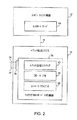
所望であれば、スイッチ14は、制御ソフトウェアを実行し、パケット処理回路32を省いた、図2の汎用処理プラットフォームを用いて実装することができる。このタイプの構成が図2に示される。図2の例証となる構成に示されるように、コンピューティング機器12上のコントローラ・サーバ18は、ネットワーク・リンク16上で、スイッチ(パケット転送システム)14上のコントローラ・クライアント30と通信することができる。コントローラ・サーバ18は、例えば、フロー・テーブル28内に維持されるフロー・テーブル・エントリをコントローラ・クライアント30に伝送することができる。パケット処理ソフトウェア40は、ネットワーク・インターフェース38を用いて、パケット(例えば、ポート34を用いて送受信されるパケット)を転送し、他の方法で処理することができる。ネットワーク・インターフェース38は、スイッチ14内のシステム・ボード(一例として)にプラグ接続された1つ又はそれ以上のネットワーク・インターフェースを用いて実装することができる。
If desired, the
別の例示的なタイプのネットワーク・スイッチが、図3に示される。図3の例においては、コンピューティング機器42は、仮想マシン44を実装するために用いられる。コンピューティング機器42は、例えば、1つ又はそれ以上のコンピュータに基づくサーバとすることができ、仮想マシン44は、ウェブ・サーバ又は他のオンライン・サービスを実装するために用いることができる。典型的なシナリオにおいては、仮想マシンサービスを購入した顧客に、仮想マシン44の番号が割り当てられることがある。これらの仮想マシンが互いに通信できることを保証するために、コンピューティング機器42のリソースの一部を用いて、ネットワーク・スイッチ14(例えば、パケット処理ソフトウェア40のようなソフトウェア、フロー・テーブル28、及びコントローラ・クライアント30に基づいたパケット処理システム)を実装する。仮想スイッチと呼ばれることもあるスイッチ14は、それぞれの仮想マシン44間でパケットを転送できる1つのタイプのパケット転送システムを形成する。
Another exemplary type of network switch is shown in FIG. In the example of FIG. 3, the
図1のネットワーク・スイッチ14のようなネットワーク・スイッチは、1つ又はそれ以上の高速スイッチング集積回路(「スイッチIC」)に結合された制御回路を用いて実装することができる。このタイプの構成が、図4に示される。図4に示されるように、コンピューティング機器12上のコントローラ・サーバ18は、経路16を介してネットワーク・スイッチ14と通信することができる。スイッチ14は、処理回路24と、スイッチIC32−1...スイッチIC32−Nのような1つ又はそれ以上の関連したスイッチIC32とを含むことができる。制御回路24は、例えば、マイクロプロセッサ及びメモリに基づくことができる。スイッチIC32−1...IC32−Nは、高速でパケット処理タスクを処理することができる専用スイッチング回路とすることができる。一例として、制御回路24は、500MHzのマイクロプロセッサに基づくことができ、スイッチIC32−1...IC32−Nは、入力・出力ポート34の48からのデータを処理することができ、その各々は、(一例として)1−10Gbpsの関連したデータ転送速度を有する。
A network switch, such as network switch 14 of FIG. 1, may be implemented using a control circuit coupled to one or more fast switching integrated circuits (“switch ICs”). This type of configuration is shown in FIG. As shown in FIG. 4, the
図1のネットワーク・スイッチ14を実装する際に用いることができる別の例証としてのスイッチ・アーキテクチャが、図5に示される。図5の例において、スイッチ(パケット転送システム)14は、プロセッサ24−1のようなマスター・プロセッサと、スレーブ・プロセッサ24−2のような1つ又はそれ以上の関連したスレーブ・プロセッサとを含むことができる。スイッチIC32及びプロセッサ24−2のようなスレーブ・プロセッサは、ライン・カード48のようなライン・カード上に実装することができる。ライン・カード50のような1つ又はそれ以上のライン・カードは、処理回路(例えば、マイクロプロセッサ及びメモリ)を含むことができる。ライン・カード48及び50は、バックプレーン52を用いて相互接続することができる。
Another illustrative switch architecture that can be used in implementing the
図5に示されるタイプの構成の場合、コントローラ・サーバは、ライン・カードの処理リソースを用いて実装することができる。例えば、コントローラ・サーバは、図5のコントローラ・サーバ18−Bにより示されるように、ライン・カード50上に実装することができる。所望であれば、コントローラ・サーバは、コンピューティング機器12上に実装することができる(例えば、図5のコントローラ・サーバ18−Aのように)。コントローラ・サーバ18−A又はコントローラ・サーバ18−Bは、プロセッサ24−1及び/又は24−2のようなプロセッサを用いて実装されるコントローラ・クライアント30と通信することができる。コントローラ・サーバ18−Aとコントローラ・クライアントとの間の通信は、ネットワーク接続16上で行われ得る。コントローラ・サーバ18−Bとコントローラ・クライアントとの間の通信は、バックプレーン52上で(例えば、TCP/IPのようなプロトコルを用いたネットワーク接続上で)行われ得る。
For the type of configuration shown in FIG. 5, the controller server can be implemented using line card processing resources. For example, the controller server can be implemented on the
図6に示されるように、コントローラ・サーバ18及びコントローラ・クライアント30は、ネットワーク・プロトコル・スタック58及びネットワーク・プロトコル・スタック60のようなネットワーク・プロトコル・スタックを用いて、ネットワーク経路66上で通信することができる。スタック58及び60は、例えば、Linux TCP/IPスタック又はVxWorksオペレーティング・システムにおけるTCP/IPスタックとすることができる(例として)。経路66は、例えば、スイッチ14と外部機器との間のネットワーク接続をサポートする経路(例えば、図1のネットワーク経路16)とすることができ、又は図5に示されるような、スイッチ14のバックプレーン52におけるネットワーク接続をサポートする経路とすることができる。経路66が経路16のようなネットワーク経路である構成が、一例として本明細書で説明されることもある。
As shown in FIG. 6,
制御プロトコル・スタック56は、ネットワーク・プロトコル・スタック58と制御ソフトウェア54との間のインターフェースとして働く。制御プロトコル・スタック62は、ネットワーク・プロトコル・スタック60と制御ソフトウェア64との間のインターフェースとして働く。動作中、コントローラ・サーバ18がコントローラ・クライアント30と通信するとき、制御プロトコル・スタック56は、制御プロトコル・メッセージ(例えば、ポートを作動させ又は特定のフロー・テーブル・エントリをフロー・テーブル28にインストールするための制御メッセージ)を生成し、構文解析する。図6に示されるタイプの構成を用いることにより、コントローラ・サーバ18とコントローラ・クライアント30との間のリンク上に、ネットワーク接続が形成される。コントローラ・サーバ18とコントローラ・クライアント30は、インターネット・プロトコル(IP)ネットワーク接続上で、伝送制御プロトコル(Transmission Control Protocol、TCP)又はユーザ・データグラム・プロトコル(User Datagram Protocol、UDP)を用いて通信することができる。ネットワーク接続上でコントローラ・サーバ18とコントローラ・クライアント30との間で通信するときに用いることができる制御プロトコルの例として、SNMP及びOpenFlowプロトコル・スタック・バージョン1.0.0が挙げられる(例として)。
The
フロー・テーブル28は、複数のフィールド(ヘッダ・フィールドと呼ばれることがある)を有するフロー・テーブル・エントリ(例えば、テーブルにおける行)を含む。スイッチ14により受信されたパケット・フィールドを、フロー・テーブルのフィールドと比較することができる。各々のフロー・テーブル・エントリは、関連したアクションを有することができる。パケット・フィールドと、フロー・テーブル・エントリのフィールドとの間に一致がある場合、そのフロー・テーブル・エントリについての対応するアクションをとることができる。
The flow table 28 includes a flow table entry (eg, a row in the table) having a plurality of fields (sometimes referred to as header fields). The packet field received by the
例証となるフロー・テーブルが、図7に示される。図7Aに示されるように、テーブル28は、フロー・テーブル・エントリ(行)68を有することができる。各々のフロー・テーブル・エントリは、ヘッダ70、アクション72、及び統計データ74と関連付けることができる。ヘッダ70は各々、複数のヘッダ・フィールド76を含むことができる。各々のフロー・テーブル・エントリにおけるアクションは、パケット・フィールドと、そのフロー・テーブル・エントリのヘッダの対応するフィールドとの間に一致が検出されたときに、スイッチ14がパケットに対してどのアクションを行うべきかを示す。スイッチ14は、統計データ(カウンタ値)をフロー・テーブル28の統計データ部分内に維持することができ、この統計データには、スイッチ14の性能についての情報を得ることが望まれる場合、コントローラ・サーバ18により照会することができる。
An illustrative flow table is shown in FIG. As shown in FIG. 7A, the table 28 may have flow table entries (rows) 68. Each flow table entry can be associated with a
ヘッダ70のヘッダ・フィールド(及び、各着信パケットの対応するフィールド)は、以下のフィールド、すなわち入力ポート(すなわち、パケットが受信される、スイッチ14の物理ポートのアイデンティティ)、イーサネット送信元アドレス、イーサネット宛先アドレス、イーサネットのタイプ、仮想ローカル・エリア・ネットワーク(VLAN)id、VLAN優先順位、IP送信元アドレス、IP宛先アドレス、IPプロトコル、IP ToS(サービスのタイプ)ビット、トランスポート送信元ポート/インターネット制御メッセージ・プロトコル(ICMP)タイプ(送信元TCPポートと呼ばれることもある)、及びトランスポート宛先ポート/ICMPコード(宛先TCPポートと呼ばれることがある)を含むことができる。所望であれば、他のフィールドを用いることができる。
The header field of header 70 (and the corresponding field of each incoming packet) includes the following fields: input port (ie identity of physical port of
各々のフロー・テーブル・エントリ(フロー・エントリ)は、スイッチが一致するパケットをどのように処理するかを命令する、ゼロ又はそれ以上のアクションと関連付けられる。転送アクションが存在しない場合、パケットはドロップされることが好ましい。パケット・フィールドと、フロー・テーブル・エントリのヘッダ・フィールドとの間に一致が検出された場合、スイッチ14が取り得るアクションは、以下のアクション、すなわち、転送(例えば、着信インターフェースを含まない全てのインターフェース上でパケットを送信するためのALL、パケットをカプセル化し、コントローラ・サーバに送信するためのCONTROLLER、パケットをスイッチのローカル・ネットワーキング・スタックに送信するためのLOCAL、フロー・テーブル28におけるアクションを行うためのTABLE、パケットを入力ポートの外に送信するためのIN_PORT、例えば、伝統的なレベル2、VLAN、及びレベル3の処理を用いて、スイッチによりサポートされるデフォルト転送経路によってパケットを処理するためのNORMAL、及び着信インターフェースを含まない最小スパニンング・ツリーに沿ってパケットをフラッドさせるためのFLOOD)を含むことができる。スイッチ14が取ることができる付加的なアクションは、ポートに取り付けられたキューを通してパケットを転送するためのエンキュー・アクション、及びドロップ・アクション(例えば、指定されたアクションなしに、フロー・テーブル・エントリと一致するパケットをドロップするための)を含む。(フィールド修正(Modify−field)アクションをスイッチ14によりサポートすることもできる。取り得るフィールド修正アクションの例は、VLAN IDの設定(Set VLAN ID)、VLAN優先順位の設定(Set VLAN priority)、VLANヘッダの除去(Strip VLAN header)、イーサネット送信元アドレスMAC(媒体アクセス制御)アドレスの修正(Modify Ethernet source MAC address)の修正、イーサネット宛先MACアドレスの修正(Modify Ethernet destination MAC address)、IPv4送信元アドレスの修正(Modify IPv4 source address
、Modify IPv4 Tosビット、Modify IPv4 ToSビットの修正(Modify IPv4 ToS bits)、トランスポート宛先ポートの修正(Modify transport destination port)を含む。
Each flow table entry (flow entry) is associated with zero or more actions that dictate how the switch handles matching packets. If there is no transfer action, the packet is preferably dropped. If a match is detected between the packet field and the header field of the flow table entry, the actions that the
, Modify IPv4 Tos bit, Modify IPv4 ToS bit (Modify IPv4 ToS bits), and Modify transport destination port (Modify transport destination port).
図7Bは、3つのフロー・テーブル・エントリを有する例証となるフロー・テーブルである。エントリは、ワイルドカード(例えば、「*」記号)を有するフィールドを含む。特定のフィールド内にワイルドカードが存在する場合、着信パケット内のフィールドの特定の値に関係なく、全ての着信パケットは、フィールドに対する「一致」を形成すると考えられる。 FIG. 7B is an illustrative flow table having three flow table entries. The entry includes a field with a wildcard (eg, “*” symbol). If there is a wildcard in a particular field, all incoming packets are considered to form a “match” for the field, regardless of the specific value of the field in the incoming packet.
図7Bのテーブルの第1行のエントリは、フロー・テーブル・エントリが動作しているスイッチが、イーサネットのスイッチングを行うように指示する。特に、一致するイーサネット宛先アドレスを有する着信パケットは、ポート3に転送される。
The entry in the first row of the table of FIG. 7B instructs the switch on which the flow table entry is operating to perform Ethernet switching. In particular, incoming packets with matching Ethernet destination addresses are forwarded to
図7Bのテーブルの第2行のエントリは、インターネットの経路指定を行うために(すなわち、パケットはその宛先IPアドレスに基づいて転送される)、スイッチをどのように構成するかを示す。 The entry in the second row of the table of FIG. 7B shows how to configure the switch for Internet routing (ie, packets are forwarded based on their destination IP address).
図7Bのテーブルの第3行は、ファイヤウォール処理を行うのに、どのようにスイッチを構成できるかを示すエントリを含む。宛先IPポート値が80であるパケットを受信すると、そのパケットはドロップされる(すなわち、スイッチは、ポート80のトラフィックをブロックするファイヤウォールとして働くように構成される)。
The third row of the table of FIG. 7B includes an entry indicating how the switch can be configured to perform firewall processing. When a packet with a destination IP port value of 80 is received, the packet is dropped (ie, the switch is configured to act as a
図7Bに示されるタイプのフロー・テーブル・エントリは、システムの設定動作中にコントローラ・サーバ18によりスイッチ14にロードすることができ、又は、コントローラ・サーバ18におけるスイッチ14からのパケットの受信及び処理に応答して、リアルタイムでコントローラ・サーバ18からスイッチ14に与えることができる。多数のスイッチ14を有するネットワークにおいては、ネットワークを通して経路を形成するために、各スイッチに、適切なフロー・テーブル・エントリを与えることができる。
A flow table entry of the type shown in FIG. 7B can be loaded into the
一例として、それぞれのエンド・ホスト間に直列に接続された第1及び第2のスイッチを含むネットワークを考える。トラフィックをエンド・ホストの第1のものからエンド・ホストの第2のものに送信する場合、第1及び第2のスイッチを通じてトラフィックを経路指定することが望ましい。第2のスイッチが第1のスイッチのポート3に接続されている場合、第2のエンド・ホストが第2のスイッチのポート5に接続されている場合、及び第2のエンド・ホストの宛先IPアドレスが172.12.3.4である場合、コントローラ・サーバ18は、第1のスイッチに、図7Cのフロー・テーブル・エントリを与え、かつ、第2のスイッチに、図7Dのフロー・テーブル・エントリを与えることができる。宛先IPアドレス172.12.3.4を有するパケットが、第1のスイッチにおいて受信された場合、これらは、図7Cのテーブルにおける「ポート3に転送」アクションに従って、第2のスイッチに転送される。これらのパケットが第2のスイッチにおいて受信された場合、図7Dにおける「ポート5に転送」アクションに従って、第2のスイッチのポート5に接続された第2のエンド・ホストに転送される。
As an example, consider a network that includes first and second switches connected in series between respective end hosts. When sending traffic from a first one of the end hosts to a second one of the end hosts, it is desirable to route the traffic through the first and second switches. If the second switch is connected to
入力・出力ポート34上で受信されたパケットを処理する際にスイッチ14によって行うことができる例証となるステップが、図8に示される。ステップ78において、スイッチ14は、そのポートの1つ(例えば、図1の入力・出力ポート34の1つ)においてパケットを受信する。
Illustrative steps that can be performed by the
ステップ80において、スイッチ14は、受信したパケット・フィールドを、そのスイッチのフロー・テーブル28におけるフロー・テーブル・エントリのフィールドと比較して、一致があるかどうかを判断する。フロー・テーブル・エントリにおける幾つかのフィールドは、完全な値(すなわち、完全なアドレス)を含むことができる。他のフィールドは、ワイルドカードを含むことができる(すなわち、「*」の「don’t care」ワイルドカード文字でマーク付けされたフィールド)。さらに他のフィールドは、部分的に完全なエントリ(すなわち、部分的にワイルドカード指定された部分アドレス)を有することができる。幾つかのフィールドは、範囲を用いることができ(例えば、TCPのポート番号を1から4096までの間の値に制限することにより)、事実上、この範囲を用いて、1つのタイプの部分的ワイルドカード指定を実施することができる。受信したパケットとフロー・テーブル・エントリとの比較を行う際、スイッチ14は、フロー・テーブル・エントリにおける各フィールドが、いずれのワイルドカード指定もない完全な値、ワイルドカード指定を有する部分的な値、又はワイルドカード文字(すなわち、完全にワイルドカード指定されたフィールド)を含むかどうか考慮することができる。
In
ステップ80の動作中、パケット・フィールドとフロー・テーブル・エントリの対応するフィールドとの間に一致がないと判断された場合、スイッチ14は、リンク16上でパケットをコントローラ・サーバ18に送信することができる(ステップ84)。
During the operation of
ステップ80の動作中、パケットとフロー・テーブル・エントリとの間に一致があると判断された場合、スイッチ14は、そのフロー・テーブル・エントリと関連付けられたアクションを実行し、かつ、そのフロー・テーブル・エントリの統計フィールドにおけるカウンタ値を更新することができる(ステップ82)。次いで、線86で示されるように、処理は、ステップ78にループバックすることができるので、スイッチ14により別のパケットを処理することができる。
If it is determined during operation of
図9は、複数の関連したネットワーク接続16を用いて、コントローラ・サーバ18が複数のスイッチ14をどのように制御できるかを示す例証となるネットワークの図である。図9に示される例証となるネットワークにおいて、第1のエンド・ホスト(図9の左側のエンド・ホスト88)は、第2のエンド・ホスト(図9の右側のエンド・ホスト88)と通信する。エンド・ホスト88は、コンピュータ(例えば、パーソナル・コンピュータ)、サーバ、コンピュータのクラスタ、セットトップ・ボックス、手持ち式機器、又はいずれかの他のコンピューティング機器とすることができる。エンド・ホスト88の間の通信の一部の間、第1のエンド・ホストはパケット送信元として働くことができ、第2のエンド・ホストはパケット宛先として働くことができる。あるときには、役割を逆にすることができ、第2のエンド・ホストがパケット送信元として働き、一方、第1のエンド・ホストがパケット宛先として働くことができる。
FIG. 9 is an illustrative network diagram illustrating how a
ネットワークを通してパケットが正しく転送されることを保証するために、コントローラ18は、図9に示されるスイッチの各々に、適当なフロー・テーブル・エントリを与えることができる。1つの適切な構成において、コントローラ・サーバ18は、着信パケットとそのフロー・テーブル・エントリとの間に一致を検出しなかったスイッチからコントローラ・サーバ18に送信されたパケットの受信に応答して、スイッチ14に、フロー・テーブル・エントリを与えることができる。コントローラ・サーバ18がパケットを受信すると、コントローラ・サーバ18は、スイッチ14のフロー・テーブル28についての適切なエントリを判断するのに、ネットワーク構成規則20(図1)、パケットからの情報、ネットワーク・トポロジー情報、及び他の情報を用いることができる。次に、コントローラ・サーバ18は、フロー・テーブル・エントリをスイッチ14に与えて、ネットワークを通してパケットを転送するように、スイッチを構成することができる。別の適切な構成の場合、コントローラ・サーバ18は、設定動作中に、フロー・テーブル28をスイッチ28に与える。
In order to ensure that packets are forwarded correctly through the network, the
コントローラ・サーバ18が、スイッチからパケットを受信する前に又はその受信に応じてリアルタイムで、スイッチ14にフロー・テーブル・エントリを与えるかどうかに関係なく、ひとたび各スイッチ14にフロー・テーブル・エントリが与えられると、フロー・テーブル・エントリは、スイッチ14が、ネットワークを通して満足のいく経路に沿ってパケットを転送することを保証する。
Regardless of whether
スイッチ14のリソースに過負荷をかけないように注意しなければならない。通常、各スイッチ14のフロー・テーブルの容量は制限されている。スイッチの容量は、例えば、10,000を超えないフロー・テーブル・エントリを処理するように、そのスイッチを制限することができる。この制限を超過するのを回避するために、異なるネットワーク位置におけるスイッチに、異なるレベルの特定性(specificity)を有する規則を実装するフロー・テーブル・エントリを与えることができる。
Care must be taken not to overload the resources of the
一例として、図10のネットワーク10を考える。図10のネットワーク10において、エンド・ホスト88は、ネットワーク10のエッジ部分10Eにおけるエッジ・スイッチ14E、ネットワーク10の集約・分散部分10ADにおける集約スイッチ14AD、及びネットワーク10のコア部分10Cにおけるコア・スイッチ14C(その1つ又はそれ以上がインターネットに結合される)を通して通信する。エンド・ホスト88の各々と関連したアクティブなユーザが存在し得る。典型的なエッジ・スイッチ14Eは、約50の異なるエンド・ホスト88に接続することができる(一例として)。典型的には、集約スイッチ14ADは、約20のエッジ・スイッチ14Eに接続することができる(一例として)。このアーキテクチャの結果として、集約スイッチ10ADは、約1000のエンド・ホスト88からのトラフィックを処理する必要があり得る。
As an example, consider the
アクティブなユーザは、ウェブ・ブラウザ、及び多数のネットワーク接続をもたらす他のアプリケーションを用いることができるので、集約スイッチ14ADが、10,000乃至20,000又はそれ以上のネットワーク接続を処理するように要求されることもある。集約スイッチ14ADのハードウェアが、最大10,000のフロー・テーブル・エントリしか処理できない場合、ネットワーク10が過負荷になる可能性があるので、幾つかの所望のネットワーク接続が、ユーザに利用不能になる。
An active user can use a web browser and other applications that provide a large number of network connections, so the aggregation switch 14AD requests that 10,000 to 20,000 or more network connections be processed. Sometimes it is done. If the aggregation switch 14AD hardware can only handle a maximum of 10,000 flow table entries, the
この潜在的な問題の回避を確実にするために、コントローラ・サーバ18は、ネットワーク10の異なる部分におけるスイッチに、異なる特定性のフロー・テーブル・エントリ(一致規則)を与えることができる。例えば、エッジ・スイッチ14Eに、集約スイッチ14ADよりも制限的なエントリを与えることができ、及び/又は、集約スイッチ14ADに、コア・スイッチ14Cよりも制限的なエントリを与えることができる。このタイプの構成により、所望のレベルのパケット処理を全体的に維持することを可能にする一方で、他の場合にはその容量に追いつかなくなることがある、集約スイッチ14AD及び14Cのようなスイッチにかかる負担を軽減することができる。
To ensure avoidance of this potential problem, the
図11は、より多くのワイルドカード指定を組み込むことにより、例証となるヘッダ・フィールド(すなわち、IP宛先アドレス・フィールド)と関連した一致規則をどのようにより制限的でなくできるかを示す。図11の例において、IP宛先アドレス・フィールドに用いることができる最も制限的な値は、完全なIPアドレス「2.2.2.2」である。フロー・テーブル・エントリがこの値を有する場合、このフィールドに一致するパケットのみが、同一のIP宛先アドレス(すなわち、2.2.2.2)を含むものとなる。フロー・テーブル・エントリに用いることができる、僅かにより制限的でないIP宛先アドレス・フィールドは、「2.2.2.*」である。最後のIPアドレス位置にワイルドカードを用いることにより、2.2.2.1、2.2.2.2、2.2.2.3等のようなアドレスは全て2.2.2.*エントリと一致するので、着信パケットにおけるIP宛先アドレス・フィールドに一致するための要件が緩和される。より多くのワイルドカード指定を組み込むことにより、さらにより制限的でない一致規則がもたらされる。例えば、図11における「2.2.*」エントリは、2.2.0.0、2.2.0.1、...、2.2.1.0、2.2.1.1、...のIP宛先アドレスと一致する。フロー・テーブル・エントリ・フィールドが2.*の値を有する場合、アドレスにおける最後の3つの位置の値に関係なく、「2」で始まる全てのIP宛先アドレスが一致する。フィールド全体がワイルドカード指定された場合(すなわち、図11のIP宛先アドレス・フィールドが「*」の値を有する場合)、全ての着信パケットが、フロー・テーブルのIP宛先アドレス・フィールドに一致するとみなされるIP宛先アドレス・フィールドを含む(すなわち、「*」はあらゆるアドレス値に一致するとみなされる)。 FIG. 11 shows how by incorporating more wildcard specifications, the matching rules associated with the illustrative header field (ie, IP destination address field) can be made less restrictive. In the example of FIG. 11, the most restrictive value that can be used for the IP destination address field is the complete IP address “2.2.2.2”. If the flow table entry has this value, only packets that match this field will contain the same IP destination address (ie, 2.2.2.2). A slightly less restrictive IP destination address field that can be used for flow table entries is "2.2.2. * ". By using a wildcard at the last IP address location, all addresses such as 2.2.2.1, 2.2.2.2, 2.2.2.3, etc. will be 2.2.2. * Matches the entry, so the requirement to match the IP destination address field in the incoming packet is relaxed. Incorporating more wildcard specifications results in even less restrictive matching rules. For example, “2.2. * ” Entries in FIG. 11 include 2.2.0.0, 2.2.0.1,. . . , 2.2.1.0, 2.2.1.1,. . . Match the IP destination address. The flow table entry field is 2. If it has a value of * , all IP destination addresses starting with "2" will match regardless of the value of the last three positions in the address. If the entire field is wildcarded (ie, the IP destination address field in FIG. 11 has a value of “ * ”), all incoming packets are considered to match the IP destination address field of the flow table. IP destination address field (ie, “ * ” is considered to match any address value).
図11の例が実証するように、より多くワイルドカード指定されたフロー・テーブルの値は、より制限的でない一致規則に対応し、一方、より少なくワイルドカード指定されたフロー・テーブルの値は、より特定の一致基準に対応する。所定のネットワークにおけるパケット処理のために特定の機能を実装する場合には、ネットワークにおけるスイッチ14の少なくとも一部が詳細なフロー・テーブル・エントリ、及びそれに対応する制限的な一致規則を用いることが望ましい。例えば、ネットワーク・エッジにおける又はその近くのスイッチが、詳細なフロー・テーブル・エントリを処理できる場合がある。しかしながら、ネットワークのコアのより近くでは、図10に関連して説明されたトラフィックにおける集中のせいで、そのような詳細なフロー・テーブル・エントリが、スイッチに追いつかなくなる傾向がある。従って、ネットワーク・コアにより近いスイッチに対して、より制限的でない規則を用いることが有利であり得る。一例として、「2.2.2.2」のIP宛先アドレス・フィールドを、エッジ・スイッチ14Eにおけるフロー・テーブルに用いることができ、一方、コア・スイッチ14Cにおけるフロー・テーブル・エントリに対して、*のIP宛先アドレス・フィールドを用いることができる。コア・スイッチにおける「*」のエントリは、多数の可能な宛先IPアドレスに適用できるため、あまり制限的でない「*」値を使用することは、コア・スイッチ14Cに必要とされる異なるフロー・テーブル・エントリ数を最小にする助けとなる。
As the example of FIG. 11 demonstrates, more wildcarded flow table values correspond to less restrictive matching rules, while less wildcarded flow table values are: Corresponds to more specific matching criteria. When implementing specific functions for packet processing in a given network, it is desirable that at least some of the
一例として、図12の例証となるネットワークを考える。図12の例においては、2つのエンド・ホスト88がある。エンド・ホストEHAはパケット送信元として働くことができ、エンド・ホストEHBはパケット宛先として働くことができる。スイッチ14は、エッジ・スイッチ14Eと、スイッチ14Cのようなコア・スイッチとを含む。設定動作中、又はリアルタイムのネットワーク構成動作中、コントローラ・サーバ18は、スイッチSW E1、SW C1及びSW E2に、スイッチSW E1、SW C1及びSW E2を通じて、ネットワーク経路上で、エンド・ホストEHAからエンド・ホストEHBにパケットを転送するのに適したフロー・テーブル・エントリを与えることができる。図12のスイッチと関連した物理的な入力・出力ポートが、スイッチを接続するリンクに隣接して示される。例えば、スイッチSW E1に隣接するラベル「1」は、エンド・ホストEHAがスイッチE1のポート1に接続されることを示す。スイッチSW E1に隣接するラベル2及びスイッチSW C1に隣接するラベル「3」は、スイッチE1のポート2がスイッチSW C1のポート3に接続されることなどを示す。
As an example, consider the network illustrated in FIG. In the example of FIG. 12, there are two end hosts 88. The end host EHA can act as a packet source and the end host EHB can act as a packet destination.
1つの従来の手法を用いる場合、完全な一致規則が、ワイルドカードのないフロー・テーブル・エントリの形で、ネットワーク内のスイッチに与えられる。エントリは、スイッチがどのように着信パケットを転送するかを指定する。図13は、このタイプの構成を用いて、図12のネットワークのスイッチを与えることができるフロー・テーブル・エントリを示す。図13に示されるように、フロー・テーブル・エントリE1は、スイッチSW E1に、着信パケットをポート1からポート2に転送するように指示する。フロー・テーブル・エントリC1は、スイッチSW C1に、着信パケットをスイッチSW C1のポート3からポート4に転送するように指示する。スイッチSW E2は、フロー・テーブル・エントリE2に従って、着信パケットをスイッチSW E2のポート5からポート6に転送する。従って、図13のフロー・テーブル・エントリは、図12のネットワーク10において、パケットをエンド・ホストEHAからEHBに流れさせる。このタイプの手法は、フロー・テーブル・エントリにおいてワイルドカードを使用することを必要とせず、このことは、フロー・テーブル・エントリがスイッチの容量に追いつかなくなる状況をもたらし得る。例えば、スイッチC1のようなスイッチには、多数のエッジ・スイッチ及びエンド・ホストについてのフロー・テーブル・エントリを与える必要があり得る。スイッチSW C1内に格納する必要があるフロー・テーブル・エントリの数が、スイッチSWC1のハードウェア能力を上回ることがある。
With one conventional approach, perfect match rules are given to switches in the network in the form of flow table entries without wildcards. The entry specifies how the switch forwards incoming packets. FIG. 13 shows a flow table entry that can be used to provide a switch of the network of FIG. 12 using this type of configuration. As shown in FIG. 13, the flow table entry E1 instructs the switch SW E1 to transfer the incoming packet from
この問題に対処する従来の構成が、図14に示される。図14の構成では、フロー・テーブル・エントリの選択されたフィールド内に、ワイルドカード指定が用いられる。例えば、図14の各フロー・テーブル・エントリの物理ポートのフィールドが、ワイルドカードを有する。これにより、各エンド・ホストが取り付けられる物理ポートの識別情報に関係なく、スイッチに結合されたエンド・ホストの全てからのパケットが、同じく処理されることが可能になる。物理ポートの情報に基づいてパケットを異なるように処理する試みは行われないため(及び、図14のテーブルにおける他のワイルドカード指定情報のため)、必要とされるフロー・テーブル・エントリの数は低減する。 A conventional configuration that addresses this problem is shown in FIG. In the configuration of FIG. 14, wildcard designation is used in the selected field of the flow table entry. For example, the physical port field of each flow table entry in FIG. 14 has a wild card. This allows packets from all of the end hosts coupled to the switch to be processed the same, regardless of the identification information of the physical port to which each end host is attached. Since no attempt is made to process packets differently based on physical port information (and because of other wildcard specification information in the table of FIG. 14), the number of flow table entries required is To reduce.
図14の従来の手法は、低減した数のフロー・テーブル・エントリを用いて、パケットをエンド・ホストEHAからエンド・ホストEHBに転送するのを可能にするが、セキュリティが危険にさらされる。特に、スイッチは物理ポートの情報に基づいてトラフィックをブロックできないため、図14の手法は、攻撃者が物理ポートをスプーフィング(spoof)するのを可能にする。 The conventional approach of FIG. 14 allows a packet to be forwarded from end host EHA to end host EHB using a reduced number of flow table entries, but security is compromised. In particular, since the switch cannot block traffic based on physical port information, the approach of FIG. 14 allows an attacker to spoof a physical port.
フロー・テーブル・エントリからネットワークのスイッチ(例えば、集約スイッチ及びコア・スイッチ)に課される負担を減らしながら、所望のレベルのネットワーク性能を維持するために(例えば、セキュリティを維持するために)用いることができるスキームが、図15のフロー・テーブル・エントリにより示される。フロー・テーブル・エントリE1’、C1’及びE2’をネットワークの異なる部分にあるスイッチに与えることができる。例えば、エントリE1’及びE2’を、それぞれ図12のスイッチSW E1及びSW E2に用いることができ、エントリC1’をスイッチ14Cに用いることができる。フロー・テーブル・エントリE1’、C1’及びE2’は、異なるレベルの制限性を有することができる。特に、ネットワークのコアにより近いスイッチ(例えば、図12のコア・スイッチSW C1についてのエントリC1’)のための一致規則は、より多くのワイルドカード指定を有することができ、かつ、ネットワークのコアからより遠くにあるスイッチ(例えば、エッジ・スイッチ14EについてのエントリE1’及びE2’)のための一致規則より制限的でないものとすることができる。
Used to maintain a desired level of network performance (eg, to maintain security) while reducing the burden placed on network switches (eg, aggregation switches and core switches) from flow table entries. A possible scheme is shown by the flow table entry in FIG. Flow table entries E1 ', C1' and E2 'can be provided to switches in different parts of the network. For example, entries E1 'and E2' can be used for switches SW E1 and SW E2 in FIG. 12, respectively, and entry C1 'can be used for
例えば、スイッチSW E1に、着信パケットをどのように転送するかを指示するのに用いることができる、エントリE1’のようなフロー・テーブル・エントリは、物理ポートの入力フィールド及びIP送信元アドレスのフィールド内に特定の情報を含むことができ、一方、集約スイッチ又はコア・スイッチSW C1に、着信パケットをどのように転送するかを指示するのに用いることができる、エントリC1’のようなフロー・テーブル・エントリは、少なくとも幾つかのワイルドカード指定を含むことができる。図15の例の場合、エントリE1’(スイッチSW E1により用いられる)及びエントリE2’(スイッチSW E2により用いられる)の両方とも、完全なフィールドのみを含み、ワイルドカード指定を有するフィールドは含んでおらず、一方、エントリC1’は、完全にワイルドカード指定された複数のフィールド(すなわち、物理入力ポート、IP送信元アドレス、宛先TCPポート、及び送信元TCPポート)を含む。 For example, a flow table entry, such as entry E1 ', that can be used to instruct switch SW E1 how to forward an incoming packet, includes a physical port input field and an IP source address. A flow such as entry C1 ′ that can contain specific information in the field, but can be used to instruct the aggregation switch or core switch SW C1 how to forward incoming packets. A table entry can contain at least some wildcard specifications. In the case of the example of FIG. 15, both entry E1 ′ (used by switch SW E1) and entry E2 ′ (used by switch SW E2) contain only complete fields and fields with wildcard designations. On the other hand, the entry C1 ′ includes a plurality of completely wildcarded fields (ie, physical input port, IP source address, destination TCP port, and source TCP port).
C1’エントリのようなエントリは、E1’及びE2’エントリのようなエントリより多くのワイルドカード指定を含むので、C1’エントリのようなエントリを用いることは、コア・スイッチSWC1(本例において)が維持するフロー・テーブル・エントリの数を減らす助けとなる。これにより、スイッチSW C1へのフロー・テーブルの負担が減り、スイッチ14に追いつかなくなるのを防ぐ助けとなる。同時に、エッジ・スイッチSW E1及びSW E2(本例において)に対応するフロー・テーブル・エントリの完全性のために、セキュリティが保護される。エントリE1’及びE2’は、物理ポートの情報を保持し、かつ、コア・スイッチC1にアクセスすることができないので、物理ポートのスプーフィングは可能でない(エンド・ホストをコア・スイッチC1に物理的に直接接続できないと仮定して)。
Since entries such as C1 ′ entries contain more wildcard specifications than entries such as E1 ′ and E2 ′ entries, using an entry such as C1 ′ entry is the core switch SWC1 (in this example). Helps reduce the number of flow table entries maintained. This reduces the load of the flow table on the switch SW C1 and helps prevent the
コントローラ・サーバ18は、図15に示されるタイプのテーブルについてのフロー・テーブル・エントリを選択的に分散させることができる。例えば、コントローラ・サーバ18は、フロー・テーブル・エントリE1’のようなフロー・テーブル・エントリを、スイッチSW C1のようなネットワーク・コアにより近いスイッチではなく、スイッチE1のようなエッジ・スイッチに分散させ、かつ、フロー・テーブル・エントリC1’のようなフロー・テーブル・エントリを、エッジ・スイッチではなく、スイッチSW C1のようなコア・スイッチ又はコアに近いスイッチに分散させることができる。
図16は、エッジ・スイッチのフロー・テーブル・エントリがワイルドカード指定を含むスキームについてのフロー・テーブル・エントリを示す。例えば、図12のスイッチSW E1についてのエントリE1’’により示されるように、宛先TCPポート・フィールドをワイルドカード指定し、かつ、送信元TCPポート・フィールドをワイルドカード指定することができる。図12のスイッチSW E2についてのエントリE2’’により示されるように、IP送信元アドレス・フィール及び送信元TCPポートをワイルドカード指定することができる。パケットにおける送信元TCPポート情報は、IPリンクを確立する通常のプロセスの一部としてランダムに割り当てられ(戻りトラフィックが適切なエンド・ホスト処理に向けられることを保証するために)、かつ、通常有用なセキュリティ情報は含まないため、送信元TCPポートにワイルドカード指定を使用することにより、セキュリティを低減させずに、フロー・テーブル・エントリを低減させることが可能になる。E1’’エントリにおける宛先TCPポート情報のワイルドカード指定は、スイッチSW E1が、エンド・ホストEHBにおける権限のないTCPポートに向かうその関連したエンド・ホストEHAからのトラフィックをブロックすることができないので、セキュリティ上の問題をもたらす可能性がある。それにもかかわらず、宛先TCPポート・フィールドは、フロー・テーブル・エントリE2’’において22の完全な(ワイルドカード指定のない)エントリで満たされているので、スイッチSW E2は、この所望のトラフィック・ブロック動作を行うことができる。 FIG. 16 shows a flow table entry for a scheme in which the edge switch flow table entry includes a wildcard designation. For example, as indicated by entry E1 ″ for switch SW E1 in FIG. 12, the destination TCP port field can be wildcarded and the source TCP port field can be wildcarded. As indicated by the entry E2 ″ for the switch SW E2 in FIG. 12, the IP source address field and source TCP port can be wildcarded. The source TCP port information in the packet is randomly assigned as part of the normal process of establishing an IP link (to ensure that return traffic is directed to proper end host processing) and is usually useful Since no security information is included, it is possible to reduce flow table entries without reducing security by using a wildcard designation for the source TCP port. Since the wildcard designation of the destination TCP port information in the E1 '' entry cannot switch traffic from its associated end host EHA towards the unauthorized TCP port in the end host EHB, the switch SW E1 May cause security problems. Nevertheless, because the destination TCP port field is filled with 22 complete (no wildcard designation) entries in the flow table entry E2 ″, switch SW E2 Block operation can be performed.
従って、図16のフロー・テーブル・エントリにおいて幾つかのワイルドカード指定が存在していても、パケット転送機能の全体的な損失はない。エントリE1’’のワイルドカード指定により失われたどの機能も、フロー・テーブル・エントリE2’’のより完全なフィールドの機能によって埋め合わせられるので、図15の例において実行された同じパケット処理機能が、図16の例において実行される。図15の例におけるように、エントリC1’’のようなコア・スイッチのフロー・テーブル・エントリは、スイッチSW C1により維持されなければならないフロー・テーブル・エントリの総数を減らすために、ワイルドカード指定(例えば、ネットワーク・エッジにより近いスイッチについてのフロー・テーブル・エントリより多いワイルドカード指定)を含むことができる。 Accordingly, there is no overall loss of packet forwarding functionality even if there are several wildcard designations in the flow table entry of FIG. Since any function lost due to the wildcard specification of entry E1 '' is compensated by the more complete field function of flow table entry E2 '', the same packet processing function performed in the example of FIG. This is executed in the example of FIG. As in the example of FIG. 15, the core switch flow table entry, such as entry C1 ″, can be wildcarded to reduce the total number of flow table entries that must be maintained by switch SW C1. (E.g., more wildcard specifications than flow table entries for switches closer to the network edge).
図17は、ネットワークの異なる位置において異なるレベルの特定性を有するフロー・テーブル・エントリ(すなわち、ネットワークのエッジにおける又はこれに近いスイッチに対してはより制限的であり、ネットワークのコア又はその近くであまり制限的ではないフロー・テーブル・エントリ)を含むネットワークを動作させる際に必要とされる例証となるステップのフローチャートである。 FIG. 17 shows flow table entries with different levels of specificity at different locations in the network (ie, more restrictive for switches at or near the edge of the network and at or near the core of the network. FIG. 6 is a flowchart of illustrative steps required in operating a network that includes a less restrictive flow table entry).
ステップ90の動作中、コントローラ・サーバ18はネットワーク機器を識別し、ネットワークのトポロジーを判断することができる。例えば、ステップ92の動作中、コントローラ・サーバ18は、各スイッチ14の能力を判断することができる。ステップ94の動作中、コントローラ・サーバ18は、ネットワークのレイアウトについての情報(例えば、どのスイッチ及びエンド・ホストが、スイッチにおける入力・出力ポートの各々に接続されているか等)を得ることができる。スイッチ能力について収集することができる情報は、各スイッチにおける最大公称フロー・テーブル容量(例えば、各スイッチにおいて処理することができるフロー・テーブル・エントリの公称最大数)、フロー・テーブル・エントリを処理するためのスイッチの実際の現在の容量(すなわち、スイッチのフロー・テーブル内に現在存在する新しいフロー・テーブル・エントリについての空いている行の数)、各スイッチが行うことができるアクションのタイプ等を含む。所望であれば、ネットワーク内のエンド・ホストの能力についての情報を収集することができる。エンド・ホストの能力について収集することができる情報は、どのタイプの処理がサポートされるか、及びどの接続規則がそれらのプロセスと関連付けられるか(例えば、エンド・ホスト番号Xは、いずれかのエンド・ホストがポート80を用いて接続するのを可能にするウェブ・サーバである)情報を含む。ネットワーク・トポロジー情報は、どのスイッチ・ポートが互いに接続されているか、幾つのエンド・ホストが各スイッチに取り付けられるか、幾つの他のスイッチが各スイッチに接続されるか、及びエンド・ホストが取り付けられたポートのアイデンティティについての情報を含むことができる。ネットワークのトポロジーを判断するために、コントローラ・サーバ18は、リンク層検出プロトコル(LLDP)パケットのようなプローブ・パケットをネットワーク全体にわたって送信することができる。スイッチ及び他のネットワーク・コンポーネントは、コントローラ・サーバにより照会されたときに、それらの能力についての情報を戻すことができる。ステップ90の動作は、ネットワーク10の動作中連続的に行うことができる。
During operation of
ステップ94の動作中にネットワークのトポロジーを判断する際、コントローラ・サーバ18は、スイッチ14を、主にネットワーク・エッジ10E、集約(集約・分散)ネットワーク部分10AD、又はネットワーク・コア10Cと関連付けられたものとしてカテゴリ化することができる(例えば、図10を参照されたい)(例えば、スイッチ14を、エッジ・ネットワーク・スイッチとして又は非エッジ・スイッチとしてカテゴリ化する)。測定基準を各々のスイッチに適用して、スイッチがエッジ・スイッチであるか(例えば、スイッチが多数のエンド・ホストに接続されている場合)、又は非エッジ・スイッチであるか(例えば、スイッチがどのエンド・ホストにも接続されていない及び/又は監視ホストにだけ接続されている場合)を判断することができる。測定基準を各々の非エッジ・スイッチに適用して、非エッジ・スイッチが集約スイッチであるか(例えば、スイッチが多数のエッジ・スイッチに接続されている場合)、又はコア・スイッチであるか(例えば、集約スイッチ又はコア・スイッチに接続されており、エッジ・スイッチにほとんど又は全く接続されていないスイッチ)を判断することができる。
In determining the network topology during the operation of
1つの例証となる測定基準では、スイッチが1つ又はそれ以上のエンド・ホスト(例えば、多数のエンド・ホスト)に接続されている場合、スイッチをエッジ・スイッチとしてカテゴリ化することができ、スイッチがエンド・ホストに接続されておらず、及び/又は1つのホスト(又は、場合によっては1つより多いホスト)に排他的に又は主として監視目的のために接続されている場合、非エッジ・スイッチとしてカテゴリ化することができる。スイッチ14をカテゴリ化する際にコントローラ・サーバ18により用いることができる別の例証としての測定基準では、第1のスイッチが第2のスイッチより多くのエンド・ホストに接続されている場合、第1のスイッチは、第2のスイッチよりエッジ様のものとしてカテゴリ化することができる。第1のスイッチがエンド・ホストより多くの取り付けられたスイッチを有し、かつ、第2のスイッチがエンド・ホストより少ない取り付けられたスイッチを有する場合、第1の非エッジ・スイッチは、第2の非エッジ・スイッチよりコア様(非エッジ様)であるとみなすことができる。所望であれば、スイッチをカテゴリ化するのに、他の測定基準を用いることができる。これらは、単に説明に役立つ実例にすぎない。ひとたび判断されると、スイッチのカテゴリは、ネットワーク構成中に適切なフロー・テーブル・エントリを分散させる際に用いることができる。
In one illustrative metric, if a switch is connected to one or more end hosts (eg, multiple end hosts), the switch can be categorized as an edge switch and the switch A non-edge switch if it is not connected to an end host and / or is connected exclusively or primarily for monitoring purposes to one host (or possibly more than one host) Can be categorized as: Another illustrative metric that can be used by the
ステップ96の動作中、コントローラ・サーバ18は、パケット送信元(例えば、図12のエンド・ホストEHAのようなエンド・ホスト88の1つ)からパケット宛先(例えば、図12のエンド・ホストEHBのようなエンド・ホスト88の1つ)に送信されたパケットに対して、ネットワーク10を通る適切な経路を判断することができる。コントローラ・サーバ18は、ステップ90の動作中に収集した情報のような情報を用いて、パケットについての適切な経路を判断することができる。経路は、ネットワーク設定動作中に識別することができ、又は、コントローラ・サーバ18においてスイッチ14の1つからのパケット(例えば、パケットを受信したが、パケットに対する一致を生じたフロー・テーブル・エントリは含まなかったスイッチによりコントローラ・サーバ18に送信されたパケット)の受信に応答して、リアルタイムで判断することができる。
During the operation of
ステップ98の動作中、コントローラ・サーバ18は、ステップ96の動作中に識別された経路及びネットワーク構成規則20(図1)を用いて、完全なフロー・テーブル・エントリ(すなわち、図13に示されるタイプのエントリ)を生成することができる。ネットワーク構成規則20は、どのエンド・ホストがどのサービスにアクセスできるか(所望であれば、集合エンド・ホストを用いて)の規則を含むことができる。これらのネットワーク構成規則は、コントローラ・サーバ18が生成するフロー・テーブル・エントリのセットにおいて具体化することができる。例えば、特定のエンド・ホストが特定のサービスにアクセスできない場合、このタイプの権限のないアクセスを防ぐように(例えば、ポートをブロックすること等により)フロー・テーブル・エントリを構築することができる。ステップ98において生成されたフロー・テーブル・エントリは、好ましくは完全なフィールド(ワイルドカード指定のないフィールド)を含み、従って、ネットワークについての完全なパケット転送機能を維持する。
During operation of
図10及び図12に関連して説明されたように、スイッチ14におけるフロー・テーブル・エントリの全てに対して、完全な(ワイルドカード指定のない)フィールドを用いると、スイッチ14に、具体的にはネットワークのエッジから離れたところに位置するスイッチに負担がかかることがある。これらのスイッチが過負荷にならないことを保証するために、コントローラ・サーバ18は、ステップ100の動作中、ステップ98のフロー・テーブル・エントリの圧縮バージョンを生成することができる。図15及び図16に関連して説明されたように、これらのフロー・テーブル・エントリは、必要とされるフロー・テーブル・エントリ数を低減させるためにワイルドカード指定を含んでいる。インテリジェントなワイルドカード割り当てを用いて、スイッチ14の所望のパケット転送機能が、ステップ98で生成されたフロー・テーブル・エントリに対して保護されることを保証することができる。例えば、エッジ・スイッチが物理ポート情報を維持することを保証することにより(すなわち、非エッジ・スイッチのみについての物理ポート情報をワイルドカード指定することにより)、物理ポートのスプーフィングを防ぐためのネットワーク・スイッチの能力を保護することができる。別の例として、ワイルドカード指定されていない適切なTCPポートのフィールドがエッジ・スイッチのエントリに保持されることを保証することによって、TCPポートのブロックを実装するためのスイッチの能力を保持することができる。
As described in connection with FIGS. 10 and 12, using a complete (no wildcard designation) field for all of the flow table entries in
ステップ98の動作を行う際、サーバ・コントローラ18は、スイッチに、ネットワーク内のそれらの位置に合わせたフロー・テーブル・エントリが与えられることを保証することができる。ネットワーク・エッジにおける又はその近くのネットワーク・スイッチ(例えば、エッジ・スイッチ)のために、より制限的なフロー・テーブル・エントリを用いることができ、一方、ネットワーク・コアのより近くにあるスイッチ(例えば、非エッジ・スイッチ)のために、より制限的でないフロー・テーブルのエントリを用いることができる。スイッチの位置、公称スイッチ容量、実際のスイッチ容量等のような要因に基づいて、フロー・テーブル・エントリをスイッチに与えることができる。
In performing the operation of
ネットワークにおけるコア・スイッチが、フロー・テーブルを含み、かつ、コントローラ18により調整可能である場合、コア・スイッチには、集約スイッチについてのフロー・テーブル・エントリと同じだけ制限的な又はそれより制限的ではないフロー・テーブル・エントリを与えることができる。幾つかのネットワークにおいて、コア・スイッチは、コントローラ・サーバ18とは独立して動作するコントローラにより制御することができ、かつ、コントローラ・サーバ18と互換性がないものとすることができる。このタイプの状況において、コア・スイッチは、それぞれのコントローラを用いて構成できるので、コントローラ・サーバ18は、コア・スイッチに、フロー・テーブル・エントリを与える必要がない。
If the core switch in the network includes a flow table and is adjustable by the
典型的なシナリオにおいて、コントローラ・サーバ18は、エッジ・スイッチ14Eに、ワイルドカード指定されるフィールドがほとんどないか又は全くない、完全な又はほぼ完全なフロー・テーブル・エントリを与えることができる。集約スイッチ14ADのような非エッジ・スイッチには、より制限的でないフロー・テーブル・エントリを与えることができる。例えば、集約スイッチ14ADには、その唯一の完全なフィールドが宛先IPフィールドであり、その他のフィールドは完全な又は部分的なワイルドカードを含むフロー・テーブル・エントリを与えることができる。コア・スイッチ14Cがコントローラ18によって制御されない場合、コア・スイッチ14Cのような非エッジ・スイッチには、コントローラ18からフロー・テーブル・エントリを与える必要はない。しかしながら、コア・スイッチ14Cがコントローラ18により制御される場合、コントローラ18は、部分的にワイルドカード指定された宛先IPアドレスを除いて、完全にワイルドカード指定されたフロー・テーブル・エントリをコア・スイッチ14Cに与えることができる。一例として、コア・スイッチについてのフロー・テーブル・エントリは、宛先IPアドレス・フィールドを除いて、全てのフィールドにおいてワイルドカードを有することができる。コア・スイッチについてのフロー・テーブル・エントリにおける宛先IPアドレス・フィールドには、「171.64.123.*」のような部分的にワイルドカード指定された値を与えることができ(所望のサブネットにアドレス指定されたパケットと一致するように)、この部分的にワイルドカード指定された宛先IPアドレス・フィールドに対応するアクションは、「ポート3に送信する」とすることができる。
In a typical scenario, the
ひとたびステップ100のフロー・テーブル・エントリが生成されると、コントローラ・サーバ18は、これらのフロー・テーブル・エントリを適切なスイッチ14に分散させることができる。スイッチ14がこのように構成される場合、パケットは、パケットの送信元とパケット宛先との間でネットワーク10を通じて流れることができる。
Once the flow table entries for
所望であれば、ステップ98の動作をステップ10の動作と結合させることができる(すなわち、ステップ98の完全なフロー・テーブル・エントリを計算する中間ステップを行うことなく、経路及びネットワーク構成規則から、選択的なワイルドカード指定を含む圧縮されたフロー・テーブル・エントリを直接生成することができる。)
If desired, the operation of
図18は、図17のステップ90の動作を行う際(すなわち、ネットワーク10のトポロジー及びそのスイッチ14の能力を判断するとき)に必要とし得る動作を示す。ステップ104の動作中、コントローラ・サーバ18は、適切な測定基準(例えば、取り付けられたエンド・ホストの数、取り付けられたスイッチの数等に基づいた測定基準)を用いて、ネットワーク10内のそれらの位置に応じてスイッチをカテゴリ化することができる。例えば、1つ又はそれ以上のエンド・ホスト88に接続されたスイッチをエッジ・スイッチとしてカテゴリ化することができる。他のスイッチ14は、ネットワークのトポロジー内の位置、及び/又は、取り付けられたスイッチの数等などの要因に基づいて、ネットワーク・コア10C、又は、ネットワーク10ADの集約・分散部分に属するとカテゴリ化することができる。
FIG. 18 illustrates operations that may be required when performing the operation of
ステップ106及び108の動作中、コントローラ・サーバ18は、ネットワーク接続16上で、ネットワーク10内の個々のスイッチ14にクエリを発行することができる。例えば、コントローラ・サーバ18は、ステップ106の動作中、その公称容量についてスイッチ14に照会することができる。スイッチ14は、その公称容量(すなわち、いずれの既存のエントリもない場合、スイッチが処理することができるフロー・テーブル・エントリの理論上の最大数)についての情報で応答することができる。実際の容量の情報について照会された場合(ステップ108)、スイッチ14は、コントローラ・サーバ18に、その実際の(現在の)容量についての情報(すなわち、スイッチの能力を超過することなく、スイッチにロードすることができる付加的なフロー・テーブル・エントリの数)を与えることができる。ステップ90の動作中に収集される情報は、ネットワーク10におけるスイッチについての適切なフロー・テーブル・エントリを生成する際に(例えば、フロー・テーブル・エントリによりスイッチに追いつかなくならないように、図17のステップ96、98及び100の動作中、スイッチ14についてのフロー・テーブル・エントリをどのように生成するかを判断する際に)用いることができる。
During operation of
図19の例証となるネットワーク10において、エンド・ホストEHC及びEHDは、スイッチSW E3及びSW E4のようなエッジ・スイッチ14E、及び、コア・スイッチSW C2のようなコア・スイッチ14Cを介して、インターネット110に結合される。コア・スイッチSW C2は、デフォルトのインターネット・ゲートウェイDGによりインターネットに結合することができる。本例において、エンド・ホスト機器112のようなインターネット機器は、3.3.3.3の関連したIPアドレスを有することができる。エンド・ホストEHCは、1.1.1.1のIPアドレスを有することができ、かつ、TCPポート22と関連付けることができる。エンド・ホストEHDは、2.2.2.2のIPアドレスを有することができ、かつ、TCPポート22と関連付けることができる。
In the
図19の例証となるネットワークのようなネットワークにおいて、コントローラ・サーバ18は、ネットワークにおいて使用中のサブネットの知識を有し得る。この情報に基づいて、コントローラ・サーバ18は、ネットワーク内に「3」で始まるIPアドレスを含むエンド・ホストがない(すなわち、ネットワーク10内に、3.*の有効なIP宛先アドレスがない)と結論付けることができる。このことは、コントローラ・サーバ18が、3.*のIPアドレスを有するトラフィックをデフォルトのゲートウェイDGに転送するフロー・テーブルを構築することを可能にする。ネットワーク10内に、3.*の宛先アドレスがないので、この転送タスクを行う際に、フロー・テーブル・エントリ内の他のフィールドの値を必要としない。
In a network such as the exemplary network of FIG. 19, the
図20は、図19のネットワーク10においてこのタイプのパケット転送スキームを実装するために用いることができる例証となるフロー・テーブルである。スイッチSW E3により用いることができるフロー・テーブル・エントリE3により示されるように、エンド・ホストEHCから宛先IPアドレス3.3.3.3へのパケットは、スイッチSW E3のポート2に転送される(送信元アドレス・ポート5における2.2.2.2を有する、転送ポートと同じタイプのエントリを、エンド・ホストEHDからのパケットのために用いることができる)。スイッチSW C2により用いることができるフロー・テーブルのエントリC2により示されるように、IP宛先アドレスが「3.*」に一致する全てのパケットがポート7に、従って、ゲートウェイDGに転送される。フロー・テーブル・エントリC2における他のフィールドをワイルドカード指定し、必要とされるフロー・テーブル・エントリの数を最小にすることができる。
FIG. 20 is an illustrative flow table that can be used to implement this type of packet forwarding scheme in the
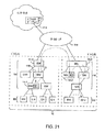
ネットワーク10のための別の可能なトポロジーが、図21に示される。このタイプの構成では、ネットワークのドメインA及びBが、コントローラ・サーバ18からフロー・テーブルをロードすることができるスイッチ14にポピュレートされる。技術的な制限のため又は許可がないために、介在するローカル・コア114におけるネットワーク・スイッチは、コントローラ・サーバ18からフロー・テーブル・エントリがロードされず、コントローラ・サーバ18からフロー・テーブル・エントリをロードすることができない。
Another possible topology for the
コントローラ・サーバ18により与えられるフロー・テーブル・エントリの制御下でドメインA及びBが機能するのを可能にするために、ネットワーク・トンネル(例えば、仮想ローカル・エリア・ネットワーク・トンネル)を、ローカル・コア・ネットワーク114を通して確立することができる。このトンネルは、ネットワーク10の1つのドメイン(例えば、ドメインA)においてカプセル化エンジンを用いて他方のドメインに向かうデータ・トラフィックをカプセル化し、ネットワーク10の他方のドメイン(例えば、ドメインB)においてカプセル化解除(deencapsulation)エンジンを用いてカプセル化解除し、従って、カプセル化されたデータを復旧することにより、形成することができる。ネットワーク10におけるカプセル化エンジン及びカプセル化解除エンジンは、Generic Routing Encapsulation(GRE)、マルチプロトコル・ラベル・スイッチング(Multiprotocol Label Switching、MPLS)、仮想ローカル・エリア・ネットワーク(VLAN)カプセル化技術、ネットワーク・トンネルのデータをカプセル化するための他の技術等といったカプセル化方法を用いることができる。
To allow domains A and B to function under the control of flow table entries provided by
スイッチ14の利用可能なハードウェア及びソフトウェア能力に起因して、特定のスイッチ14が、カプセル化エンジン及びカプセル化解除エンジンを実行するのにより適していることがある。例えば、ドメインAにおけるスイッチ14−1は、カプセル化エンジンEEを実行するのに適切であり、ドメインBにおけるスイッチ14−2は、カプセル化解除エンジンDEを実行するのに適切であり得る。カプセル化エンジンEE及びカプセル化解除エンジンDEが実装されるスイッチは、ローカル・コア114に直接接続される必要はない。図21に示されるように、例えば、1つ又はそれ以上の他のスイッチ14(例えば、カプセル化エンジン又はカプセル化解除エンジンを有さないスイッチ)を、スイッチ14−1とローカル・コア114との間に置くことができ、スイッチ14の1つ又はそれ以上(例えば、カプセル化エンジン又はカプセル化解除エンジンを有さないスイッチ)をスイッチ14−2とローカル・コア114との間に置くことができる。
Due to the available hardware and software capabilities of
トラフィックがローカル・コア114を通って(すなわち、コントローラ・サーバからのフロー・テーブル・エントリにより制御されていないネットワークの部分を通って)進むことができるのを確実にするために、コントローラ・サーバ18は、パケットをネットワーク10の各ドメイン内に転送するフロー・テーブル・エントリを生成し、トラフィックがエンジンEE及びDEにより適切にカプセル化及びカプセル化解除されるようにすることができる。例えば、トラフィックがドメインAのエンド・ホストEH1によりドメインBのエンド・ホストEH2に送信される場合、コントローラ・サーバ18は、パケットを、経路116に沿ってスイッチを通ってEH1からスイッチ14−1上のカプセル化エンジンEEに転送し、カプセル化エンジンEEによりカプセル化されたパケットを、経路118に沿ってローカル・コア114を通ってスイッチ14−2上のカプセル化解除エンジンDEに転送し、かつ、カプセル化解除エンジンDEによりカプセル化解除されたパケットを、経路120を介してエンド・ホスト88に転送するフロー・テーブル・エントリを生成することができる。パケットが取る経路は、特定のスイッチを複数回通ることができる。例えば、パケットは、経路116に沿って流れているときに最初に、経路118に沿って流れているとき二回目に、スイッチ14−3を通過することができ、かつ、経路118に沿って流れているとき最初に、経路120に沿って流れているときに二回目にスイッチ14−4を通過することができる(本例において)。
To ensure that traffic can travel through the local core 114 (ie, through portions of the network that are not controlled by flow table entries from the controller server), the
図21のネットワーク10のスイッチのためのフロー・テーブル・エントリを生成するのに必要とされる例証となるステップのフローチャートが、図22に示される。ステップ122の動作中、コントローラ・サーバ18は、ネットワーク10のトポロジーについての情報(例えば、ドメインA及びBの機器の位置、間に置かれたローカル・コア114又はコントローラ・サーバ18により制御されていない他の機器の性質)、フロー・テーブル・エントリの能力及び各スイッチ14の他の能力(例えば、コア114を通してネットワーク・トンネルを形成するためのあらゆるカプセル化エンジンEE及びカプセル化解除エンジンの位置)、並びに他のネットワーク情報を収集することができる。
A flowchart of illustrative steps required to create a flow table entry for the switch of
ステップ122の動作中に収集された情報に基づいて、コントローラ・サーバ18は、ステップ124において、カプセル化エンジンEE、ローカル・コア114、及びカプセル化解除エンジンDEを通して、エンド・ホストEH1からエンド・ホストEH2にトラフィックを指向させる、図21の経路116、118及び120のような経路を識別することができる。次に、コントローラ・サーバ18は、これに応じて、ステップ126において、適切なフロー・テーブル・エントリを有するスイッチ14をロードすることによって、ネットワークを構成することができる。ネットワーク10の動作中、エンド・ホストEH1からのトラフィックは、ローカル・コア114のネットワーク・スイッチを通り抜け、エンド・ホストEH2に到達する。
Based on the information collected during the operation of
より制限的なフロー・テーブル・エントリを、非エッジ・スイッチではなく、エッジ・スイッチに対して用いることにより、ネットワーク10において安全な通信を保証することができる。例えば、エッジ・スイッチには、特定の物理ポート上のホストが特定のアドレス(例えば、IP送信元アドレス、イーサネット送信元アドレス、VLANタグ、又はイーサネット・アドレス+VLANタグといったこれらと他のフィールドとの組み合わせ)を用いることを要求するフロー・テーブル・エントリを与えることができる。図23の例は、エッジ・スイッチについてのフロー・テーブル・エントリが、関連したアドレス情報に加えて、特定の物理ポート情報(例えば、ポート=4)をどのように含むことができるかを示す。このタイプの構成の場合、エッジ・スイッチ上のフロー・テーブルは、物理ポートのフィールド及び関連したアドレス・フィールドのためのワイルドカードをもたない。エッジ・スイッチのフロー・テーブル・エントリが指定する転送アクション又は他のアクションは、物理ポート及びパケットのアドレスの両方がフロー・テーブル・エントリにより確立された基準を満たす場合にのみ実行される。
By using more restrictive flow table entries for edge switches rather than non-edge switches, secure communication in
非エッジ・スイッチ(例えば、集約スイッチ)には、より制限的でないフロー・テーブル・エントリを与えることができる。例えば、図23の例証となる非エッジ・スイッチのフロー・テーブル・エントリにより示されるように、集約スイッチには、物理ポートがワイルドカード指定され、かつ、転送を決定するためにアドレス・フィールド情報だけが使用されるフロー・テーブル・エントリを与えることができる。エッジ・スイッチは、悪意のあるホストからの攻撃を防ぐフロー・テーブル・エントリを含むので、集約スイッチは、エッジ・スイッチからの着信パケットにおけるアドレス情報が信頼できると考えることができる。 Non-edge switches (eg, aggregation switches) can be provided with less restrictive flow table entries. For example, as shown by the illustrative non-edge switch flow table entry of FIG. 23, the aggregation switch has a physical port wildcarded and only the address field information to determine forwarding. Can be used to provide a flow table entry. Since the edge switch includes a flow table entry that prevents attacks from malicious hosts, the aggregation switch can consider the address information in incoming packets from the edge switch to be reliable.
例えば、エッジ・スイッチの1つに接続された悪意あるエンド・ホストが、別のエンド・ホストになりすまそうとして、IP送信元アドレスを偽造しようとする場合、悪意あるエンド・ホストが接続されるエッジ・スイッチは、悪意あるエンド・ホストの物理ポートに対して適切な一致を検出しない。悪意あるホストが接続されたエッジ・スイッチにおけるフロー・テーブル・エントリは、物理ポート番号情報及びアドレス情報の両方を含む。アドレスが悪意あるエンド・ホストによって成功裏に偽造された場合でも、悪意あるエンド・ホストからのいずれのパケットも、悪意あるエンド・ホストと関連した物理ポート情報を含み、なりすまされたエンド・ホストの正しい物理ポート情報は含まない。悪意あるエンド・ホストの物理ポートは、エッジ・スイッチのフロー・テーブル・エントリにおける要求される物理ポートと一致しないため、エッジ・スイッチは、パケットを悪意あるエンド・ホストから集約スイッチに転送せず、なりすましの試みは失敗する。 For example, if a malicious end host connected to one of the edge switches tries to impersonate another end host and forges an IP source address, the malicious end host is connected The edge switch does not detect an appropriate match for the physical port of the malicious end host. The flow table entry at the edge switch to which the malicious host is connected includes both physical port number information and address information. Even if the address is successfully forged by a malicious end host, any packet from the malicious end host contains physical port information associated with the malicious end host, and the spoofed end host The correct physical port information is not included. Since the physical port of the malicious end host does not match the requested physical port in the edge switch flow table entry, the edge switch does not forward packets from the malicious end host to the aggregation switch, Impersonation attempts fail.
1つの実施形態によれば、コントローラ・サーバを用いて、ネットワーク内のネットワーク・スイッチにフロー・テーブル・エントリを与える方法が提供される。各々のネットワーク・スイッチは、パケット・フィールドをフロー・テーブル・エントリのフィールドと比較することにより、パケットを処理する。この方法は、コントローラ・サーバによって、スイッチの幾つかをエッジ・ネットワーク・スイッチとしてカテゴリ化し、コントローラ・サーバによってネットワーク・スイッチを非エッジ・スイッチとしてカテゴリ化することを含む。この方法は、コントローラ・サーバによって、異なるフロー・テーブル・エントリを、非エッジ・スイッチとしてカテゴリ化されたネットワーク・スイッチではなく、エッジ・ネットワーク・スイッチとしてカテゴリ化されたネットワーク・スイッチに分散させることを含む。 According to one embodiment, a method is provided for providing a flow table entry to a network switch in a network using a controller server. Each network switch processes the packet by comparing the packet field with the field of the flow table entry. The method includes categorizing some of the switches as edge network switches by the controller server and categorizing the network switches as non-edge switches by the controller server. This method allows the controller server to distribute different flow table entries to network switches categorized as edge network switches rather than network switches categorized as non-edge switches. Including.
別の実施形態によれば、フロー・テーブル・エントリを分散させることは、フロー・テーブル・エントリを、ネットワーク接続上でコントローラ・サーバから、ネットワーク・スイッチ上の対応するコントローラ・クライアントに分散させることを含む。 According to another embodiment, distributing the flow table entry comprises distributing the flow table entry from the controller server over the network connection to the corresponding controller client on the network switch. Including.
別の実施形態によれば、フロー・テーブル・エントリを分散させることは、コントローラ・サーバにおけるネットワーク・プロトコル・スタックを用いて、ネットワーク接続上で、コントローラ・クライアントにおける対応するネットワーク・プロトコル・スタックと通信することを含む。 According to another embodiment, distributing the flow table entries communicates with the corresponding network protocol stack at the controller client over the network connection using the network protocol stack at the controller server. Including doing.
別の実施形態によれば、フロー・テーブル・エントリを分散させることは、完全なフィールドのみを有するフロー・テーブル・エントリをエッジ・スイッチに分散させて、少なくとも幾つかのワイルドカード指定されたフィールドを有するフロー・テーブル・エントリを非エッジ・スイッチに分散させることを含む。 According to another embodiment, distributing the flow table entries distributes the flow table entries that have only complete fields to the edge switch, so that at least some of the wildcarded fields are distributed. Distributing the flow table entries having to non-edge switches.
別の実施形態によれば、各々のフロー・テーブル・エントリは、送信元インターネット・プロトコル(IP)アドレス・フィールドを含み、エッジ・スイッチについての各々のフロー・テーブル・エントリの送信元IPアドレス・フィールドにはワイルドカードがなく、非エッジ・スイッチについての各々のフロー・テーブル・エントリの送信元IPアドレス・フィールドは、少なくとも幾つかのワイルドカード指定を含む。 According to another embodiment, each flow table entry includes a source internet protocol (IP) address field, and the source IP address field of each flow table entry for the edge switch. There are no wildcards, and the source IP address field of each flow table entry for a non-edge switch contains at least some wildcard designations.
別の実施形態によれば、ネットワーク・スイッチはポートを含み、フロー・テーブル・エントリは、ネットワーク・スイッチがパケットをポートのどれに転送すべきかを指定するアクション・フィールドを含む。 According to another embodiment, the network switch includes a port and the flow table entry includes an action field that specifies to which of the ports the network switch should forward the packet.
1つの実施形態によれば、第1の組のエンド・ホスト及びネットワーク・スイッチと関連した第1のネットワーク・ドメインと、第2の組のエンド・ホスト及びネットワーク・スイッチと関連した第2のネットワーク・ドメインと、第1のネットワーク・ドメイン及び第2のネットワーク・ドメイン内のネットワーク・スイッチに対してフロー・テーブル・エントリを与えるコントローラ・サーバと、ローカル・コア・ネットワークとを有するネットワークを動作させる方法が提供される。各々のネットワーク・スイッチは、パケット・フィールドをフロー・テーブル・エントリのフィールドと比較することによって、パケットを処理する。カプセル化エンジンが第1のネットワーク・ドメイン内のネットワーク・スイッチの1つの上に実装され、カプセル化解除エンジンが第2のネットワーク・ドメイン内のネットワーク・スイッチの1つの上に実装される。この方法は、制御サーバによって、第1のドメイン及び第2のドメイン内のネットワーク・スイッチに、パケットを第1のネットワーク・ドメイン内の第1のエンド・ホストからカプセル化エンジンに転送し、カプセル化されたパケットを、ローカル・コア・ネットワークを通じてカプセル化エンジンからカプセル化解除エンジンに転送し、かつ、パケットをカプセル化解除エンジンから第2のドメイン内の第2のエンド・ホストに転送するように指示する、第1のドメイン内のネットワーク・スイッチ及び第2のドメイン内のネットワーク・スイッチについてのフロー・テーブル・エントリを生成することを含む。 According to one embodiment, a first network domain associated with a first set of end hosts and network switches and a second network associated with a second set of end hosts and network switches. A method of operating a network having a domain, a controller server for providing a flow table entry for network switches in the first network domain and the second network domain, and a local core network Is provided. Each network switch processes the packet by comparing the packet field with the field of the flow table entry. An encapsulation engine is implemented on one of the network switches in the first network domain, and a decapsulation engine is implemented on one of the network switches in the second network domain. The method forwards a packet from a first end host in a first network domain to an encapsulation engine by a control server to a network switch in a first domain and a second domain for encapsulation Direct the forwarded packet from the encapsulation engine to the decapsulation engine through the local core network and forward the packet from the decapsulation engine to the second end host in the second domain Generating flow table entries for network switches in the first domain and network switches in the second domain.
別の実施形態によれば、ローカル・コア・ネットワークは、コントローラ・サーバからのフロー・テーブル・エントリによって制御されず、第1のネットワーク・ドメイン内のネットワーク・スイッチの少なくとも所与のものが、カプセル化エンジンが実装されるネットワーク・スイッチとローカル・コア・ネットワークとの間に置かれ、フロー・テーブル・エントリを生成することは、ネットワーク・スイッチに、カプセル化されたパケットを、ネットワーク・スイッチの所与のものを通じて転送するように指示するフロー・テーブル・エントリを生成することを含む。 According to another embodiment, the local core network is not controlled by flow table entries from the controller server, and at least a given one of the network switches in the first network domain is encapsulated. Creating a flow table entry, placed between the network switch on which the virtualization engine is implemented and the local core network, sends the encapsulated packet to the network switch location. Generating a flow table entry that directs forwarding through a given one.
別の実施形態によれば、ローカル・コアは、コントローラ・サーバからのフロー・テーブル・エントリをロードできないネットワーク・スイッチを含み、この方法は、コントローラ・サーバからのフロー・テーブル・エントリをネットワーク・スイッチにおける対応するコントローラ・クライアントに与えることをさらに含む。 According to another embodiment, the local core includes a network switch that cannot load a flow table entry from the controller server, and the method transfers the flow table entry from the controller server to the network switch. Further providing to a corresponding controller client at.
別の実施形態によれば、フロー・テーブル・エントリを与えることは、コントローラ・サーバ及びコントローラ・クライアントにおけるネットワーク・プロトコル・スタックを用いて、ネットワーク接続上で前記フロー・テーブル・エントリを伝達することを含む。 According to another embodiment, providing the flow table entry comprises communicating the flow table entry over a network connection using a network protocol stack at the controller server and the controller client. Including.
別の実施形態によれば、前記ネットワーク・プロトコル・スタックを用いることは、伝送制御プロトコル(TCP)/インターネット・プロトコル(IP)スタックを用いて、フロー・テーブル・エントリを伝達することを含む。 According to another embodiment, using the network protocol stack includes communicating a flow table entry using a transmission control protocol (TCP) / Internet protocol (IP) stack.
別の実施形態によれば、フロー・テーブル・エントリは、ヘッダ・フィールド及びアクション・フィールドを含み、フロー・テーブル・エントリを生成することは、ネットワーク・スイッチに、パケットをネットワーク・スイッチの少なくとも所与のものを通じて2度転送するように指示するフロー・テーブル・エントリを生成することを含む。 According to another embodiment, the flow table entry includes a header field and an action field, and generating the flow table entry sends a packet to the network switch at least for the network switch. Generating a flow table entry instructing to transfer twice through.
別の実施形態によれば、この方法は、カプセル化エンジンによって、マルチプロトコル・ラベル・スイッチング(Multiprotocol Label Switching)を用いて、カプセル化されたパケットを生成することをさらに含む。 According to another embodiment, the method further includes generating an encapsulated packet using multiprotocol label switching with an encapsulation engine.
別の実施形態によれば、この方法は、総称ルーティング・カプセル化(Generic Routing Encapsulation)を用いて、カプセル化されたパケットを生成することをさらに含む。 According to another embodiment, the method further includes generating an encapsulated packet using Generic Routing Encapsulation.
1つの実施形態によれば、デフォルトのインターネット・ゲートウェイによりインターネットに結合されたネットワークを動作させるための方法が提供される。ネットワークはエンド・ホストをデフォルトのインターネット・ゲートウェイに結合するネットワーク・スイッチを含む。この方法は、ワイルドカード指定されていない物理ポートのエントリを含むフロー・テーブル・エントリをネットワーク・スイッチ内のエッジ・スイッチに与えることと、少なくとも所与のフロー・テーブル・エントリをネットワーク・スイッチ内の非エッジ・スイッチに与えることとを含む。非エッジ・スイッチは、デフォルトのインターネット・ゲートウェイに接続されており、所与のフロー・テーブル・エントリは、ワイルドカード指定された物理ポート・フィールドを含み、かつ、部分的にワイルドカード指定されて、非エッジ・スイッチに、パケットをデフォルトのインターネット・ゲートウェイに転送するように指示する宛先インターネット・プロトコル・アドレス・フィールドを有する。 According to one embodiment, a method is provided for operating a network coupled to the Internet with a default Internet gateway. The network includes a network switch that couples the end host to a default Internet gateway. This method provides a flow table entry containing an entry for a physical port that is not wildcarded to an edge switch in the network switch, and at least a given flow table entry in the network switch. Providing to non-edge switches. The non-edge switch is connected to the default internet gateway, and a given flow table entry contains a wildcarded physical port field and is partially wildcarded, It has a destination internet protocol address field that instructs the non-edge switch to forward the packet to the default internet gateway.
別の実施形態によれば、ネットワーク・スイッチの各々は、コントローラ・サーバと通信するコントローラ・クライアントを含み、フロー・テーブル・エントリをエッジ・スイッチに与えることは、コントローラ・サーバ及びコントローラ・クライアントにおけるネットワーク・プロトコル・スタックを用いて、ネットワーク接続上で前記フロー・テーブル・エントリを伝達することを含む。 According to another embodiment, each of the network switches includes a controller client in communication with the controller server, and providing the flow table entry to the edge switch includes the network at the controller server and the controller client. Using a protocol stack to communicate the flow table entry over a network connection.
別の実施形態によれば、この方法は、各々のネットワーク・スイッチにおいて、受け取ったパケット・フィールドを、そのネットワーク・スイッチに与えられたフロー・テーブル・エントリのフィールドと比較することを含む。 According to another embodiment, the method includes, at each network switch, comparing the received packet field with a field of a flow table entry provided to that network switch.
1つの実施形態によれば、コントローラ・サーバを用いて、ネットワーク内のネットワーク・スイッチにフロー・テーブル・エントリを与える方法が提供され、ここでは、各々のネットワーク・スイッチは、パケット・フィールドをフロー・テーブル・エントリのフィールドと比較し、一致が検出された場合には対応するアクションを取ることによってパケットを処理し、エンド・ホストはネットワーク・スイッチに接続される。この方法は、コントローラ・サーバによって、ネットワーク・スイッチの第1のものが、エンド・ホストに接続された入力・出力ポートを有するエッジ・スイッチであり、ネットワーク・スイッチの第2のものがネットワーク・スイッチの第1のものに接続された入力・出力ポートを有する集約スイッチであると判断することを含む。この方法は、ネットワーク・スイッチの第1のものがエッジ・スイッチであり、ネットワーク・スイッチの第2のものが集約スイッチであるとの判断に応答して、コントローラ・サーバを用いて、第1のネットワーク・スイッチに第1のフロー・テーブル・エントリを与え、第2のネットワーク・スイッチに第2のフロー・テーブル・エントリを与えることをさらに含み、第1のフロー・テーブル・エントリは、ワイルドカード指定のない物理ポート・フィールドを含み、第2のフロー・テーブル・エントリはワイルドカード指定を有する物理ポート・フィールドを含む。 According to one embodiment, a method is provided for providing a flow table entry to a network switch in a network using a controller server, wherein each network switch flows a packet field into the flow field. The packet is processed by comparing the fields of the table entry and if a match is detected, the corresponding action is taken and the end host is connected to the network switch. In this method, the controller server causes the first network switch to be an edge switch having input and output ports connected to the end host, and the second network switch to be a network switch. Determining that the switch is an aggregation switch having input and output ports connected to the first of the first and second ports. In response to determining that the first of the network switches is an edge switch and the second of the network switches is an aggregation switch, the method uses the controller server to Providing a first flow table entry to the network switch and providing a second flow table entry to the second network switch, wherein the first flow table entry is a wildcard specification The second flow table entry includes a physical port field with a wildcard designation.
別の実施形態によれば、第1のネットワーク・スイッチに第1のフロー・テーブル・エントリを与えることは、第1のネットワーク・スイッチに、ワイルドカード指定のないインターネット・プロトコル送信元アドレス・フィールドを含むフロー・テーブル・エントリを与えることを含む。 According to another embodiment, providing the first flow table entry to the first network switch includes providing the first network switch with an internet protocol source address field without wildcard designation. Including providing a flow table entry containing.
別の実施形態によれば、第2のネットワーク・スイッチに第2のフロー・テーブル・エントリを与えることは、第2のネットワーク・スイッチに、ワイルドカード指定されたインターネット・プロトコル送信元アドレス・フィールドを含むフロー・テーブル・エントリを与えることを含む。 According to another embodiment, providing a second flow table entry to the second network switch includes providing the second network switch with a wildcarded internet protocol source address field. Including providing a flow table entry containing.
別の実施形態によれば、第1のネットワーク・スイッチはコントローラ・クライアントを含み、第2のネットワーク・スイッチはコントローラ・クライアントを含み、コントローラ・サーバは、ネットワーク・プロトコル・スタックを用いて、ネットワーク接続上でコントローラ・クライアントと通信する。 According to another embodiment, the first network switch includes a controller client, the second network switch includes a controller client, and the controller server uses a network protocol stack to connect to the network. Communicate with the controller client above.
別の実施形態によれば、ネットワーク・スイッチの第3のものが、エンド・ホストに接続され、かつ、第2のスイッチに結合され、この方法は、第3のネットワーク・スイッチに、ワイルドカード指定されたインターネット・プロトコル送信元アドレス・フィールドと、ワイルドカード指定のない物理ポート・フィールドとを含む第3のフロー・テーブル・エントリを与えることを含む。 According to another embodiment, a third one of the network switches is connected to the end host and coupled to the second switch, and the method includes a wildcard designation to the third network switch. Providing a third flow table entry that includes a configured Internet Protocol source address field and a physical port field with no wildcard designation.
別の実施形態によれば、この方法は、第1、第2、及び第3のネットワーク・スイッチのフロー・テーブル・エントリに応答して、パケットを、第1、第2、及び第3のネットワーク・スイッチを通じて、第1のネットワーク・スイッチに接続された第1のエンド・ホストから、第3のネットワーク・スイッチに接続された第2のエンド・ホストに転送することを含む。 According to another embodiment, the method responsive to the first, second, and third network switch flow table entries to send packets to the first, second, and third networks. Transferring through a switch from a first end host connected to the first network switch to a second end host connected to the third network switch.
別の実施形態によれば、第1のネットワーク・スイッチに第1のフロー・テーブル・エントリを与えることは、第1のネットワーク・スイッチに、ワイルドカード指定のないイーサネット送信元アドレス・フィールドを含むフロー・テーブル・エントリを与えることを含む。 According to another embodiment, providing the first flow table entry to the first network switch includes a flow including an Ethernet source address field without wildcard designation in the first network switch. Including providing table entries.
別の実施形態によれば、第1のネットワーク・スイッチに第1のフロー・テーブル・エントリを与えることは、第1のネットワーク・スイッチに、ワイルドカード指定のない仮想ローカル・エリア・ネットワーク・タグを含むフロー・テーブル・エントリを与えることを含む。 According to another embodiment, providing the first flow table entry to the first network switch includes providing the first network switch with a virtual local area network tag without a wildcard designation. Including providing a flow table entry containing.
別の実施形態によれば、第1のネットワーク・スイッチに第1のフロー・テーブル・エントリを与えることは、第1のネットワーク・スイッチに、ワイルドカード指定のないインターネット・プロトコル送信元アドレス、ワイルドカード指定のないイーサネット送信元アドレス、及びワイルドカード指定のない仮想ローカル・エリア・ネットワーク・タグからなる群から選択されるワイルドカード指定のないアドレスを含むフロー・テーブル・エントリを与えることを含む。本実施形態において、第2のネットワーク・スイッチに第2のフロー・テーブル・エントリを与えることは、第2のネットワーク・スイッチに所与のアドレスを含むフロー・テーブル・エントリを与えることと、パケット・フィールドが所与のアドレスと一致することを検出したことに応答して、第2のネットワーク・スイッチに、第2のネットワーク・スイッチが取るアクションを与えることを含む。 According to another embodiment, providing the first flow table entry to the first network switch includes providing the first network switch with an internet protocol source address without wildcard designation, a wildcard Including providing a flow table entry including an unspecified Ethernet source address and an address without wildcard selection selected from the group of virtual local area network tags without wildcard specification. In this embodiment, providing the second network table with the second flow table entry includes providing the second network switch with a flow table entry including a given address, In response to detecting that the field matches a given address, the second network switch is provided with an action taken by the second network switch.
上記は、本発明の原理を例証するものにすぎず、当業者であれば、本発明の範囲及び趣旨から逸脱することなく、様々な修正を行うことができる。 The foregoing is merely illustrative of the principles of the invention and various modifications can be made by those skilled in the art without departing from the scope and spirit of the invention.
10:ネットワーク
10E:エッジ部分
10AD:集約・分散部分
10C:コア部分
12、42:コンピューティング機器
14:ネットワーク・スイッチ
14E:エッジ・スイッチ
14AD:集約スイッチ
14C:コア・スイッチ
16:ネットワーク・リンク
18:コントローラ・サーバ
20:ネットワーク構成規則
22:TCPポート
24:制御ユニット
24−1:マスター・プロセッサ
24−2:スレーブ・プロセッサ
26:パケット処理ソフトウェア
28:フロー・テーブル
30:コントローラ・クライアント
32:パケット処理回路
34:入力・出力ポート
38:ネットワーク・インターフェース
40:パケット処理ソフトウェア
44:仮想マシン
48、50:ライン・カード
52:バックプレーン
54、64:制御ソフトウェア
56、62:制御プロトコル・スタック
58、60:ネットワーク・プロトコル・スタック
66:ネットワーク経路
68:フロー・テーブル・エントリ
70:ヘッダ
72:アクション
74:統計データ
76:ヘッダ・フィールド
88:エンド・ホスト
110:インターネット
112:エンド・ホスト機器
114:ローカル・コア
116、118、120:経路
EH:エンド・ホスト
DG:デフォルトのインターネット・ゲートウェイ
EE:カプセル化エンジン
DE:カプセル化解除エンジン
10:
Claims (12)
前記コントローラ・サーバによって、前記ネットワーク・スイッチの幾つかをエッジ・ネットワーク・スイッチとしてカテゴリ化し、前記ネットワーク・スイッチの幾つかを非エッジ・スイッチとしてカテゴリ化するステップと、
前記コントローラ・サーバによって、第1のフロー・テーブル・エントリのセットを、エッジ・ネットワーク・スイッチとしてカテゴリ化された前記ネットワーク・スイッチに分散させ、かつ前記第1のフロー・テーブル・エントリのセットとは異なる第2のフロー・テーブル・エントリのセットを、非エッジ・スイッチとしてカテゴリ化された前記ネットワーク・スイッチに分散させるステップと、
を含み、
前記第1及び第2のフロー・テーブル・エントリを分散させるステップは、完全なフィールドのみを有するフロー・テーブル・エントリを前記エッジ・スイッチに分散させて、少なくとも幾つかのワイルドカード指定されたフィールドを有するフロー・テーブル・エントリを前記非エッジ・スイッチに分散させるステップを含むことを特徴とする方法。 A method of providing a flow table entry to a network switch in a network using a controller server, wherein each of the network switches compares a packet field with a field of the flow table entry. And processing the packet according to
Categorizing some of the network switches as edge network switches and categorizing some of the network switches as non-edge switches by the controller server;
The controller server distributes a first set of flow table entries to the network switches categorized as edge network switches, and what is the first set of flow table entries? Distributing different second sets of flow table entries to the network switches categorized as non-edge switches;
Including
The step of distributing the first and second flow table entries includes distributing a flow table entry having only complete fields to the edge switch to provide at least some wildcarded fields. Distributing the flow table entries having to the non-edge switches.
前記第1及び第2のフロー・テーブル・エントリを分散させるステップは、前記コントロール・サーバにおけるネットワーク・プロトコル・スタックを用いて、前記ネットワーク接続上で、前記コントローラ・クライアントにおける対応するネットワーク・プロトコル・スタックと通信するステップを含むことを特徴とする、請求項1に記載の方法。 Distributing the first and second flow table entries distributes the flow table entries from the controller server over a network connection to corresponding controller clients on the network switch. Including steps,
The step of distributing the first and second flow table entries comprises using a network protocol stack at the control server and over the network connection a corresponding network protocol stack at the controller client. The method of claim 1, comprising communicating with.
前記コントローラによって、ワイルドカード指定されていない物理ポートのエントリを含むフロー・テーブル・エントリを前記ネットワーク・スイッチ内のエッジ・スイッチに与えるステップと、
前記コントローラによって、少なくとも所与のフロー・テーブル・エントリを前記ネットワーク・スイッチ内の非エッジ・スイッチに与えるステップと、
を含み、前記非エッジ・スイッチは、前記デフォルトのインターネット・ゲートウェイに接続されており、前記所与のフロー・テーブル・エントリは、ワイルドカード指定された物理ポート・フィールドを含み、かつ、部分的にワイルドカード指定されて、前記非エッジ・スイッチに、パケットを前記デフォルトのインターネット・ゲートウェイに転送するように指示する宛先インターネット・プロトコルアドレス・フィールドを有することを特徴とする方法。 A method for operating a network coupled to the internet by a default internet gateway, the network comprising a network switch coupling an end host to the default internet gateway, the network switch comprising a controller Controlled by the method,
Providing, by the controller, a flow table entry including an entry for a physical port that is not wildcarded to an edge switch in the network switch;
Providing, by the controller, at least a given flow table entry to a non-edge switch in the network switch;
The non-edge switch is connected to the default Internet gateway, the given flow table entry includes a wildcarded physical port field, and partially A method comprising a destination internet protocol address field that is wildcarded to instruct the non-edge switch to forward a packet to the default internet gateway.
前記ネットワーク・スイッチの各々において、受け取ったパケット・フィールドを、そのネットワーク・スイッチに与えられた前記フロー・テーブル・エントリのフィールドと比較するステップをさらに含むことを特徴とする、請求項5に記載の方法。 Each of the network switch includes a controller client in communication with the controller, wherein the controller includes a controller server, the step of providing the flow table entry to said edge switch, the controller server and the Communicating the flow table entry over a network connection using a network protocol stack at the controller client, the method further comprising:
6. The method of claim 5 , further comprising, at each of the network switches, comparing a received packet field with a field of the flow table entry provided to the network switch. Method.
前記コントローラによって、前記ネットワーク・スイッチの第1のものが、前記エンド・ホストに接続された入力・出力ポートを有するエッジ・スイッチであり、前記ネットワーク・スイッチの第2のものが前記ネットワーク・スイッチの前記第1のものに接続された入力・出力ポートを有する集約スイッチであると判断するステップと、
前記ネットワーク・スイッチの第1のものがエッジ・スイッチであり、前記ネットワーク・スイッチの前記第2のものが集約スイッチであるとの判断に応答して、前記コントローラを用いて、前記第1のネットワーク・スイッチに第1のフロー・テーブル・エントリを与え、前記第2のネットワーク・スイッチに第2のフロー・テーブル・エントリを与えるステップと、
を含み、前記第1のフロー・テーブル・エントリは、ワイルドカード指定のない物理ポート・フィールドを含み、前記第2のフロー・テーブル・エントリはワイルドカード指定を有する物理ポート・フィールドを含むことを特徴とする方法。 A method of providing a flow table entry to a network switch in a network using a controller , wherein each of the network switches compares a packet field with a field of the flow table entry and a match is found. If detected, process the packet by taking the corresponding action, the end host is connected to the network switch, and the method comprises:
According to the controller , the first of the network switches is an edge switch having input and output ports connected to the end host, and the second of the network switches is the network switch. Determining an aggregation switch having input and output ports connected to the first one;
In response to determining that the first one of the network switches is an edge switch and the second one of the network switches is an aggregation switch, using the controller , the first network Providing the switch with a first flow table entry and providing the second network switch with a second flow table entry;
Wherein the first flow table entry includes a physical port field without a wildcard specification and the second flow table entry includes a physical port field with a wildcard specification. And how to.
前記第2のネットワーク・スイッチに前記第2のフロー・テーブル・エントリを与えるステップは、前記第2のネットワーク・スイッチに、ワイルドカード指定されたインターネット・プロトコル送信元アドレス・フィールドを含むフロー・テーブル・エントリを与えるステップを含み、
前記第1のネットワーク・スイッチはコントローラ・クライアントを含み、前記第2のネットワーク・スイッチはコントローラ・クライアントを含み、前記コントローラは、ネットワーク・プロトコル・スタックを用いて、ネットワーク接続上で前記コントローラ・クライアントと通信することを特徴とする、請求項7に記載の方法。 Providing the first network table with the first flow table entry includes a flow table including an internet protocol source address field with no wildcard designation in the first network switch. Including giving an entry,
The step of providing the second flow table entry to the second network switch includes: a flow table including a wildcarded internet protocol source address field for the second network switch. Including the step of giving an entry,
The first network switch includes a controller client, the second network switch includes a controller client, and the controller communicates with the controller client over a network connection using a network protocol stack. The method according to claim 7 , wherein communication is performed.
前記第3のネットワーク・スイッチに、ワイルドカード指定されたインターネット・プロトコル送信元アドレス・フィールドと、ワイルドカード指定のない物理ポート・フィールドを含む第3のフロー・テーブル・エントリを与えるステップを含み、
前記第1、第2、及び第3のネットワーク・スイッチの前記フロー・テーブル・エントリに応答して、パケットを、前記第1、第2、及び第3のネットワーク・スイッチを通じて、前記第1のネットワーク・スイッチに接続された第1のエンド・ホストから、前記第3のネットワーク・スイッチに接続された第2のエンド・ホストに転送するステップをさらに含むことを特徴とする請求項8に記載の方法。 A third one of the network switches is connected to an end host and coupled to the second switch, the method comprising:
Providing the third network switch with a third flow table entry including a wildcarded internet protocol source address field and a physical port field without wildcarding;
In response to the flow table entries of the first, second, and third network switches, packets are routed through the first, second, and third network switches to the first network. 9. The method of claim 8 , further comprising forwarding from a first end host connected to the switch to a second end host connected to the third network switch. .
前記第2のネットワーク・スイッチに前記第2のフロー・テーブル・エントリを与えるステップは、前記第2のネットワーク・スイッチに、所与のアドレスを含むフロー・テーブル・エントリを与えるステップと、パケット・フィールドが前記所与のアドレスと一致することを検出したことに応答して、前記第2のネットワーク・スイッチに前記第2のネットワーク・スイッチが取るアクションを与えるステップを含むことを特徴とする、請求項7に記載の方法。 The step of providing the first flow table entry to the first network switch comprises the steps of: providing the first network switch with an internet protocol source address without wildcard designation, Ethernet transmission without wildcard designation. Providing a flow table entry including an original address and an address with no wildcard designation selected from the group consisting of a virtual local area network tag without wildcard designation;
Providing the second flow table entry to the second network switch includes providing the second network switch with a flow table entry including a given address; and a packet field. Responsive to detecting that the second network switch matches the given address, the second network switch is provided with an action taken by the second network switch. 8. The method according to 7 .
Applications Claiming Priority (3)
| Application Number | Priority Date | Filing Date | Title |
|---|---|---|---|
| US12/971,924 | 2010-12-17 | ||
| US12/971,924 US9001827B2 (en) | 2010-12-17 | 2010-12-17 | Methods for configuring network switches |
| PCT/US2011/065077 WO2012082988A1 (en) | 2010-12-17 | 2011-12-15 | Methods for configuring network switches |
Related Child Applications (1)
| Application Number | Title | Priority Date | Filing Date |
|---|---|---|---|
| JP2014234870A Division JP5913536B2 (en) | 2010-12-17 | 2014-11-19 | Method for configuring network switches |
Publications (2)
| Publication Number | Publication Date |
|---|---|
| JP2014506409A JP2014506409A (en) | 2014-03-13 |
| JP5654142B2 true JP5654142B2 (en) | 2015-01-14 |
Family
ID=46234363
Family Applications (2)
| Application Number | Title | Priority Date | Filing Date |
|---|---|---|---|
| JP2013544766A Expired - Fee Related JP5654142B2 (en) | 2010-12-17 | 2011-12-15 | Method for configuring network switches |
| JP2014234870A Active JP5913536B2 (en) | 2010-12-17 | 2014-11-19 | Method for configuring network switches |
Family Applications After (1)
| Application Number | Title | Priority Date | Filing Date |
|---|---|---|---|
| JP2014234870A Active JP5913536B2 (en) | 2010-12-17 | 2014-11-19 | Method for configuring network switches |
Country Status (4)
| Country | Link |
|---|---|
| US (1) | US9001827B2 (en) |
| EP (1) | EP2652914A4 (en) |
| JP (2) | JP5654142B2 (en) |
| WO (1) | WO2012082988A1 (en) |
Families Citing this family (121)
| Publication number | Priority date | Publication date | Assignee | Title |
|---|---|---|---|---|
| JP5888338B2 (en) * | 2010-12-27 | 2016-03-22 | 日本電気株式会社 | Communication system and communication method |
| CN110086701A (en) * | 2010-12-28 | 2019-08-02 | 日本电气株式会社 | Physical node, control device and communication means |
| WO2012096131A1 (en) * | 2011-01-13 | 2012-07-19 | 日本電気株式会社 | Network system and method of controlling path |
| CA2832019A1 (en) * | 2011-04-04 | 2012-10-11 | Nec Corporation | Network system, switch and connected terminal detection method |
| US8743885B2 (en) | 2011-05-03 | 2014-06-03 | Cisco Technology, Inc. | Mobile service routing in a network environment |
| RU2562760C2 (en) * | 2011-05-30 | 2015-09-10 | Нек Корпорейшн | Control system of communication route, and route control method |
| US9215184B2 (en) * | 2011-10-17 | 2015-12-15 | Hewlett-Packard Development Company, L.P. | Methods of and apparatus for managing non-congestion-controlled message traffic in a datacenter |
| EP2769512A4 (en) * | 2011-10-21 | 2015-06-03 | Nec Corp | Control apparatus for forwarding apparatus, control method for forwarding apparatus, communication system, and program |
| US8681794B2 (en) * | 2011-11-30 | 2014-03-25 | Broadcom Corporation | System and method for efficient matching of regular expression patterns across multiple packets |
| US8711860B2 (en) | 2011-12-22 | 2014-04-29 | Telefonaktiebolaget L M Ericsson (Publ) | Controller for flexible and extensible flow processing in software-defined networks |
| US8718064B2 (en) * | 2011-12-22 | 2014-05-06 | Telefonaktiebolaget L M Ericsson (Publ) | Forwarding element for flexible and extensible flow processing software-defined networks |
| US8521905B2 (en) | 2011-12-22 | 2013-08-27 | Telefonaktiebolaget L M Ericsson (Publ) | System for flexible and extensible flow processing in software-defined networks |
| KR101887581B1 (en) * | 2011-12-26 | 2018-08-14 | 한국전자통신연구원 | Flow-based packet transport device and packet management method thereof |
| US9866500B2 (en) * | 2012-02-29 | 2018-01-09 | Nec Corporation | Communication apparatus, communication method, communication system and program |
| US9264295B1 (en) * | 2012-03-02 | 2016-02-16 | Big Switch Networks, Inc. | Systems and methods for forwarding broadcast network packets with a controller |
| US9571523B2 (en) * | 2012-05-22 | 2017-02-14 | Sri International | Security actuator for a dynamically programmable computer network |
| US10212084B2 (en) * | 2012-06-14 | 2019-02-19 | Nec Corporation | Communication system, control apparatus, communication method, control method and program |
| US9736025B2 (en) * | 2012-07-11 | 2017-08-15 | Ca, Inc. | Determining service dependencies for configuration items |
| US20150236953A1 (en) * | 2012-09-11 | 2015-08-20 | Nec Corporation | Control device, communication system, communication method and storage medium |
| US9537793B2 (en) * | 2012-10-10 | 2017-01-03 | Cisco Technology, Inc. | Ensuring any-to-any reachability with opportunistic layer 3 forwarding in massive scale data center environments |
| FI20126105L (en) * | 2012-10-25 | 2014-04-26 | Tellabs Oy | Method and control device for configuring a software defined network |
| WO2014067065A1 (en) * | 2012-10-30 | 2014-05-08 | 华为技术有限公司 | Method, apparatus and system for implementing tunnel processing |
| BR112015010997A2 (en) * | 2012-11-28 | 2017-07-11 | Nec Corp | vlan switching apparatus, method and configuration management program |
| US9923831B2 (en) * | 2012-11-29 | 2018-03-20 | Futurewei Technologies, Inc. | Packet prioritization in a software-defined network implementing OpenFlow |
| FI20135013L (en) * | 2013-01-04 | 2014-07-05 | Tellabs Oy | Method and control device for configuring software-defined network |
| WO2014112612A1 (en) * | 2013-01-21 | 2014-07-24 | 日本電気株式会社 | Communication system, control device, and method for managing network topology |
| US8897138B2 (en) * | 2013-01-22 | 2014-11-25 | Gigamon Inc. | Systems and methods for configuring a network switch appliance |
| US9374285B1 (en) | 2013-02-07 | 2016-06-21 | Big Switch Networks, Inc. | Systems and methods for determining network topologies |
| JP5860423B2 (en) * | 2013-02-18 | 2016-02-16 | 日本電信電話株式会社 | Carrier network virtualization system and method |
| US9253035B2 (en) | 2013-02-21 | 2016-02-02 | International Business Machines Corporation | Reducing switch state size in flow-based networks |
| CN104022953B (en) * | 2013-02-28 | 2018-02-09 | 新华三技术有限公司 | Message forwarding method and device based on open flows Openflow |
| CN105210329B (en) | 2013-03-15 | 2019-06-04 | 慧与发展有限责任合伙企业 | Loop free hybrid network |
| US9130872B2 (en) * | 2013-03-15 | 2015-09-08 | Cisco Technology, Inc. | Workload based service chain insertion in a network environment |
| WO2014147197A1 (en) | 2013-03-20 | 2014-09-25 | Wolting Holding B.V. | Compiler for and method for software defined networks |
| EP2782291A1 (en) | 2013-03-20 | 2014-09-24 | Wolting Holding B.V. | Compiler for and method of software defined networking |
| CN104079492B (en) * | 2013-03-28 | 2017-10-10 | 华为技术有限公司 | The methods, devices and systems that flow table is configured in a kind of OpenFlow networks |
| FI20135413L (en) | 2013-04-23 | 2014-10-24 | Tellabs Oy | Method and device for optimizing a configuration system of a network element of a software-defined network |
| US9794379B2 (en) | 2013-04-26 | 2017-10-17 | Cisco Technology, Inc. | High-efficiency service chaining with agentless service nodes |
| KR20160006766A (en) * | 2013-05-10 | 2016-01-19 | 후아웨이 테크놀러지 컴퍼니 리미티드 | System and method for photonic switching |
| FI20135519A (en) * | 2013-05-15 | 2014-11-16 | Tellabs Oy | Network element of a software-configurable network |
| JP6236221B2 (en) * | 2013-05-22 | 2017-11-22 | 富士通株式会社 | Management program, management device, and network system |
| KR102153585B1 (en) * | 2013-06-24 | 2020-09-09 | 한국전자통신연구원 | Method and apparatus for network functions virtualization |
| US9742666B2 (en) * | 2013-07-09 | 2017-08-22 | Nicira, Inc. | Using headerspace analysis to identify classes of packets |
| CN105393492A (en) * | 2013-08-01 | 2016-03-09 | 惠普发展公司,有限责任合伙企业 | Address resolution rewriting |
| KR101378313B1 (en) * | 2013-09-12 | 2014-03-27 | 주식회사 파이오링크 | Method, appratus, system and computer-readable recording medium for assisting communication between terminal and local host by using openflow |
| WO2015066878A1 (en) * | 2013-11-07 | 2015-05-14 | 华为技术有限公司 | Control device and control method in software defined network (sdn) |
| EP2892182B1 (en) * | 2013-12-16 | 2019-06-12 | Coriant Oy | A network element for a data transfer network |
| CN105247814B (en) * | 2013-12-30 | 2018-09-21 | 华为技术有限公司 | The method and apparatus for managing the physical location of the network equipment |
| US9344337B2 (en) | 2014-03-13 | 2016-05-17 | Cisco Technology, Inc. | Service node originated service chains in a network environment |
| US9419855B2 (en) | 2014-03-14 | 2016-08-16 | Nicira, Inc. | Static routes for logical routers |
| US9647883B2 (en) | 2014-03-21 | 2017-05-09 | Nicria, Inc. | Multiple levels of logical routers |
| CN105191212B (en) * | 2014-03-25 | 2019-03-26 | 华为技术有限公司 | A kind of data stream statistics mthods, systems and devices |
| JP6287443B2 (en) * | 2014-03-26 | 2018-03-07 | 富士通株式会社 | Control device and table creation method thereof |
| US9454575B2 (en) | 2014-03-28 | 2016-09-27 | Hewlett Packard Enterprise Development Lp | Processing a metric of a component of a software-defined network |
| WO2015161404A1 (en) | 2014-04-21 | 2015-10-29 | 华为技术有限公司 | Tunnel type selection method and apparatus |
| TWI531908B (en) * | 2014-04-24 | 2016-05-01 | A method of supporting virtual machine migration with Software Defined Network (SDN) | |
| US9379931B2 (en) | 2014-05-16 | 2016-06-28 | Cisco Technology, Inc. | System and method for transporting information to services in a network environment |
| US9479443B2 (en) | 2014-05-16 | 2016-10-25 | Cisco Technology, Inc. | System and method for transporting information to services in a network environment |
| WO2015183311A1 (en) * | 2014-05-30 | 2015-12-03 | Hewlett-Packard Development Company, L.P. | Determine edge switch based on network traffic |
| US9553803B2 (en) * | 2014-06-30 | 2017-01-24 | Nicira, Inc. | Periodical generation of network measurement data |
| WO2016023148A1 (en) * | 2014-08-11 | 2016-02-18 | 华为技术有限公司 | Packet control method, switch and controller |
| US9590906B2 (en) * | 2014-09-24 | 2017-03-07 | Cisco Technology, Inc. | Network resource sharing for routing and forwarding information |
| US10417025B2 (en) | 2014-11-18 | 2019-09-17 | Cisco Technology, Inc. | System and method to chain distributed applications in a network environment |
| US9660909B2 (en) | 2014-12-11 | 2017-05-23 | Cisco Technology, Inc. | Network service header metadata for load balancing |
| USRE48131E1 (en) | 2014-12-11 | 2020-07-28 | Cisco Technology, Inc. | Metadata augmentation in a service function chain |
| US9614789B2 (en) * | 2015-01-08 | 2017-04-04 | Futurewei Technologies, Inc. | Supporting multiple virtual switches on a single host |
| US10129180B2 (en) | 2015-01-30 | 2018-11-13 | Nicira, Inc. | Transit logical switch within logical router |
| US9813323B2 (en) * | 2015-02-10 | 2017-11-07 | Big Switch Networks, Inc. | Systems and methods for controlling switches to capture and monitor network traffic |
| US10044676B2 (en) | 2015-04-03 | 2018-08-07 | Nicira, Inc. | Using headerspace analysis to identify unneeded distributed firewall rules |
| US10397114B2 (en) * | 2015-04-29 | 2019-08-27 | Hewlett Packard Enterprise Development Lp | Client communications in multi-tenant data center networks |
| US9762402B2 (en) | 2015-05-20 | 2017-09-12 | Cisco Technology, Inc. | System and method to facilitate the assignment of service functions for service chains in a network environment |
| CN106302184B (en) * | 2015-06-12 | 2020-02-14 | 华为技术有限公司 | Flow entry issuing method, flow entry storing method, related device and system |
| US9553891B1 (en) * | 2015-07-27 | 2017-01-24 | Bank Of America Corporation | Device blocking tool |
| US10230629B2 (en) | 2015-08-11 | 2019-03-12 | Nicira, Inc. | Static route configuration for logical router |
| US10075363B2 (en) | 2015-08-31 | 2018-09-11 | Nicira, Inc. | Authorization for advertised routes among logical routers |
| EP3154225B1 (en) * | 2015-10-08 | 2018-12-26 | ADVA Optical Networking SE | System and method of assessing latency of forwarding data packets in virtual environment |
| US10095535B2 (en) | 2015-10-31 | 2018-10-09 | Nicira, Inc. | Static route types for logical routers |
| US10476735B2 (en) | 2015-10-31 | 2019-11-12 | Nicira, Inc. | Representation of match conditions in logical pipeline data |
| US11044203B2 (en) | 2016-01-19 | 2021-06-22 | Cisco Technology, Inc. | System and method for hosting mobile packet core and value-added services using a software defined network and service chains |
| CN107196891B (en) * | 2016-03-15 | 2020-02-14 | 华为技术有限公司 | Data flow forwarding abnormity detection method, controller and system |
| US10187306B2 (en) | 2016-03-24 | 2019-01-22 | Cisco Technology, Inc. | System and method for improved service chaining |
| US10931793B2 (en) | 2016-04-26 | 2021-02-23 | Cisco Technology, Inc. | System and method for automated rendering of service chaining |
| WO2017188994A1 (en) * | 2016-04-29 | 2017-11-02 | Hewlett Packard Enterprise Development Lp | Transforming a service packet from a first domain to a second domain |
| US10153973B2 (en) * | 2016-06-29 | 2018-12-11 | Nicira, Inc. | Installation of routing tables for logical router in route server mode |
| TW201803314A (en) | 2016-06-29 | 2018-01-16 | 日本電氣股份有限公司 | Server, switch, communication system, communication method, and recording medium |
| US10419550B2 (en) | 2016-07-06 | 2019-09-17 | Cisco Technology, Inc. | Automatic service function validation in a virtual network environment |
| US10218616B2 (en) | 2016-07-21 | 2019-02-26 | Cisco Technology, Inc. | Link selection for communication with a service function cluster |
| US10320664B2 (en) | 2016-07-21 | 2019-06-11 | Cisco Technology, Inc. | Cloud overlay for operations administration and management |
| US10225270B2 (en) | 2016-08-02 | 2019-03-05 | Cisco Technology, Inc. | Steering of cloned traffic in a service function chain |
| US10218593B2 (en) | 2016-08-23 | 2019-02-26 | Cisco Technology, Inc. | Identifying sources of packet drops in a service function chain environment |
| US10361969B2 (en) | 2016-08-30 | 2019-07-23 | Cisco Technology, Inc. | System and method for managing chained services in a network environment |
| US10454758B2 (en) | 2016-08-31 | 2019-10-22 | Nicira, Inc. | Edge node cluster network redundancy and fast convergence using an underlay anycast VTEP IP |
| US10341236B2 (en) | 2016-09-30 | 2019-07-02 | Nicira, Inc. | Anycast edge service gateways |
| US10225187B2 (en) | 2017-03-22 | 2019-03-05 | Cisco Technology, Inc. | System and method for providing a bit indexed service chain |
| US10587479B2 (en) | 2017-04-02 | 2020-03-10 | Nicira, Inc. | GUI for analysis of logical network modifications |
| US10257033B2 (en) | 2017-04-12 | 2019-04-09 | Cisco Technology, Inc. | Virtualized network functions and service chaining in serverless computing infrastructure |
| US10884807B2 (en) | 2017-04-12 | 2021-01-05 | Cisco Technology, Inc. | Serverless computing and task scheduling |
| US10178646B2 (en) | 2017-04-12 | 2019-01-08 | Cisco Technology, Inc. | System and method to facilitate slice management in a network environment |
| US10333855B2 (en) | 2017-04-19 | 2019-06-25 | Cisco Technology, Inc. | Latency reduction in service function paths |
| US10554689B2 (en) | 2017-04-28 | 2020-02-04 | Cisco Technology, Inc. | Secure communication session resumption in a service function chain |
| US10735275B2 (en) | 2017-06-16 | 2020-08-04 | Cisco Technology, Inc. | Releasing and retaining resources for use in a NFV environment |
| US10798187B2 (en) | 2017-06-19 | 2020-10-06 | Cisco Technology, Inc. | Secure service chaining |
| CN109218059B (en) * | 2017-07-06 | 2021-09-14 | 华为技术有限公司 | Method, equipment and system for realizing fault detection |
| US10397271B2 (en) | 2017-07-11 | 2019-08-27 | Cisco Technology, Inc. | Distributed denial of service mitigation for web conferencing |
| US10673698B2 (en) | 2017-07-21 | 2020-06-02 | Cisco Technology, Inc. | Service function chain optimization using live testing |
| US10797959B2 (en) * | 2017-08-11 | 2020-10-06 | Quanta Computer Inc. | LLDP based rack management controller |
| US11063856B2 (en) | 2017-08-24 | 2021-07-13 | Cisco Technology, Inc. | Virtual network function monitoring in a network function virtualization deployment |
| US10791065B2 (en) | 2017-09-19 | 2020-09-29 | Cisco Technology, Inc. | Systems and methods for providing container attributes as part of OAM techniques |
| US11018981B2 (en) | 2017-10-13 | 2021-05-25 | Cisco Technology, Inc. | System and method for replication container performance and policy validation using real time network traffic |
| US10541893B2 (en) | 2017-10-25 | 2020-01-21 | Cisco Technology, Inc. | System and method for obtaining micro-service telemetry data |
| EP3721586B1 (en) | 2017-12-04 | 2022-07-06 | Telefonaktiebolaget LM Ericsson (publ) | Network link verification |
| US10666612B2 (en) | 2018-06-06 | 2020-05-26 | Cisco Technology, Inc. | Service chains for inter-cloud traffic |
| KR101982230B1 (en) * | 2018-07-06 | 2019-08-28 | 고려대학교 산학협력단 | Flow Rule Virtualization Apparatus and Method thereof in Programmable Network Virtualization |
| CN109194517B (en) * | 2018-09-20 | 2022-03-25 | 郑州云海信息技术有限公司 | Method and device for initializing virtual switch component |
| US10931560B2 (en) | 2018-11-23 | 2021-02-23 | Vmware, Inc. | Using route type to determine routing protocol behavior |
| US10797998B2 (en) | 2018-12-05 | 2020-10-06 | Vmware, Inc. | Route server for distributed routers using hierarchical routing protocol |
| US10938788B2 (en) | 2018-12-12 | 2021-03-02 | Vmware, Inc. | Static routes for policy-based VPN |
| CN110365663A (en) * | 2019-06-28 | 2019-10-22 | 北京淇瑀信息科技有限公司 | Access method, device and electronic equipment between a kind of isolation cluster |
| CN112491743A (en) * | 2020-11-02 | 2021-03-12 | 锐捷网络股份有限公司 | Configuration method and device of exchange chip |
| US12081395B2 (en) | 2021-08-24 | 2024-09-03 | VMware LLC | Formal verification of network changes |
| CN115002018B (en) * | 2022-08-03 | 2022-10-14 | 苏州思萃工业互联网技术研究所有限公司 | Method for optimizing distributed edge gateway and distributed edge gateway system |
Family Cites Families (14)
| Publication number | Priority date | Publication date | Assignee | Title |
|---|---|---|---|---|
| US7020166B2 (en) | 2000-10-03 | 2006-03-28 | Broadcom Corporation | Switch transferring data using data encapsulation and decapsulation |
| CN1757210A (en) * | 2003-01-15 | 2006-04-05 | 希尔纳公司 | A method and apparatus for transporting packet data over an optical network |
| US7349981B2 (en) * | 2003-12-18 | 2008-03-25 | Intel Corporation | System, apparatus, and method for string matching |
| KR20050076176A (en) | 2004-01-19 | 2005-07-26 | 삼성전자주식회사 | System and method for communicating between ipv6 mobile ad-hoc network and external network |
| KR100693059B1 (en) * | 2005-01-24 | 2007-03-12 | 삼성전자주식회사 | Apparatus and method for serving the virtual private network based mpls |
| JP2006245896A (en) * | 2005-03-02 | 2006-09-14 | Nippon Telegr & Teleph Corp <Ntt> | Network control server, user terminal accommodation node, communication network, and network control program |
| US8116312B2 (en) * | 2006-02-08 | 2012-02-14 | Solarflare Communications, Inc. | Method and apparatus for multicast packet reception |
| CN1997010B (en) * | 2006-06-28 | 2010-08-18 | 华为技术有限公司 | An implementation method for packet filtering |
| US20080189769A1 (en) | 2007-02-01 | 2008-08-07 | Martin Casado | Secure network switching infrastructure |
| US7729291B2 (en) * | 2007-10-19 | 2010-06-01 | Packetexchange, Inc. | System and method for reducing traffic in a wide area Ethernet network |
| CN101534240B (en) * | 2008-03-14 | 2012-04-25 | 华为技术有限公司 | Method, system and device for sending mapping information |
| JP5141512B2 (en) * | 2008-11-27 | 2013-02-13 | 富士通株式会社 | Communication control method and transmission apparatus |
| WO2010090182A1 (en) * | 2009-02-03 | 2010-08-12 | 日本電気株式会社 | Application switch system, and application switch method |
| EP2408155A4 (en) * | 2009-03-09 | 2015-01-28 | Nec Corp | Openflow communication system and openflow communication method |
-
2010
- 2010-12-17 US US12/971,924 patent/US9001827B2/en not_active Expired - Fee Related
-
2011
- 2011-12-15 EP EP11849775.9A patent/EP2652914A4/en not_active Withdrawn
- 2011-12-15 WO PCT/US2011/065077 patent/WO2012082988A1/en unknown
- 2011-12-15 JP JP2013544766A patent/JP5654142B2/en not_active Expired - Fee Related
-
2014
- 2014-11-19 JP JP2014234870A patent/JP5913536B2/en active Active
Also Published As
| Publication number | Publication date |
|---|---|
| US20120155467A1 (en) | 2012-06-21 |
| EP2652914A4 (en) | 2016-09-28 |
| JP5913536B2 (en) | 2016-04-27 |
| EP2652914A1 (en) | 2013-10-23 |
| JP2014506409A (en) | 2014-03-13 |
| JP2015065684A (en) | 2015-04-09 |
| US9001827B2 (en) | 2015-04-07 |
| WO2012082988A1 (en) | 2012-06-21 |
Similar Documents
| Publication | Publication Date | Title |
|---|---|---|
| JP5913536B2 (en) | Method for configuring network switches | |
| US9185056B2 (en) | System and methods for controlling network traffic through virtual switches | |
| EP3248331B1 (en) | Method for controlling switches to capture and monitor network traffic | |
| US9548896B2 (en) | Systems and methods for performing network service insertion | |
| US8923296B2 (en) | System and methods for managing network packet forwarding with a controller | |
| CN106797351B (en) | System and method for performing logical network forwarding using a controller | |
| US8416796B2 (en) | Systems and methods for managing virtual switches | |
| US10270645B2 (en) | Systems and methods for handling link aggregation failover with a controller | |
| US9654380B1 (en) | Systems and methods for determining network topologies | |
| US9008080B1 (en) | Systems and methods for controlling switches to monitor network traffic | |
| US9548900B1 (en) | Systems and methods for forwarding network packets in a network using network domain topology information | |
| US10291533B1 (en) | Systems and methods for network traffic monitoring | |
| US9356838B1 (en) | Systems and methods for determining network forwarding paths with a controller | |
| US10873476B2 (en) | Networks with multiple tiers of switches |
Legal Events
| Date | Code | Title | Description |
|---|---|---|---|
| A977 | Report on retrieval |
Free format text: JAPANESE INTERMEDIATE CODE: A971007 Effective date: 20140619 |
|
| A131 | Notification of reasons for refusal |
Free format text: JAPANESE INTERMEDIATE CODE: A131 Effective date: 20140625 |
|
| A521 | Request for written amendment filed |
Free format text: JAPANESE INTERMEDIATE CODE: A523 Effective date: 20140925 |
|
| TRDD | Decision of grant or rejection written | ||
| A01 | Written decision to grant a patent or to grant a registration (utility model) |
Free format text: JAPANESE INTERMEDIATE CODE: A01 Effective date: 20141020 |
|
| A61 | First payment of annual fees (during grant procedure) |
Free format text: JAPANESE INTERMEDIATE CODE: A61 Effective date: 20141119 |
|
| R150 | Certificate of patent or registration of utility model |
Ref document number: 5654142 Country of ref document: JP Free format text: JAPANESE INTERMEDIATE CODE: R150 |
|
| R250 | Receipt of annual fees |
Free format text: JAPANESE INTERMEDIATE CODE: R250 |
|
| R250 | Receipt of annual fees |
Free format text: JAPANESE INTERMEDIATE CODE: R250 |
|
| R250 | Receipt of annual fees |
Free format text: JAPANESE INTERMEDIATE CODE: R250 |
|
| LAPS | Cancellation because of no payment of annual fees |