JP5653932B2 - Centrifugal pump with offset volute - Google Patents
Centrifugal pump with offset volute Download PDFInfo
- Publication number
- JP5653932B2 JP5653932B2 JP2011542258A JP2011542258A JP5653932B2 JP 5653932 B2 JP5653932 B2 JP 5653932B2 JP 2011542258 A JP2011542258 A JP 2011542258A JP 2011542258 A JP2011542258 A JP 2011542258A JP 5653932 B2 JP5653932 B2 JP 5653932B2
- Authority
- JP
- Japan
- Prior art keywords
- impeller
- housing
- pump
- primary
- rotor
- Prior art date
- Legal status (The legal status is an assumption and is not a legal conclusion. Google has not performed a legal analysis and makes no representation as to the accuracy of the status listed.)
- Expired - Fee Related
Links
Images


Classifications
-
- F—MECHANICAL ENGINEERING; LIGHTING; HEATING; WEAPONS; BLASTING
- F04—POSITIVE - DISPLACEMENT MACHINES FOR LIQUIDS; PUMPS FOR LIQUIDS OR ELASTIC FLUIDS
- F04D—NON-POSITIVE-DISPLACEMENT PUMPS
- F04D29/00—Details, component parts, or accessories
- F04D29/40—Casings; Connections of working fluid
- F04D29/42—Casings; Connections of working fluid for radial or helico-centrifugal pumps
- F04D29/426—Casings; Connections of working fluid for radial or helico-centrifugal pumps especially adapted for liquid pumps
- F04D29/428—Discharge tongues
-
- A—HUMAN NECESSITIES
- A61—MEDICAL OR VETERINARY SCIENCE; HYGIENE
- A61M—DEVICES FOR INTRODUCING MEDIA INTO, OR ONTO, THE BODY; DEVICES FOR TRANSDUCING BODY MEDIA OR FOR TAKING MEDIA FROM THE BODY; DEVICES FOR PRODUCING OR ENDING SLEEP OR STUPOR
- A61M60/00—Blood pumps; Devices for mechanical circulatory actuation; Balloon pumps for circulatory assistance
- A61M60/20—Type thereof
- A61M60/205—Non-positive displacement blood pumps
- A61M60/216—Non-positive displacement blood pumps including a rotating member acting on the blood, e.g. impeller
- A61M60/226—Non-positive displacement blood pumps including a rotating member acting on the blood, e.g. impeller the blood flow through the rotating member having mainly radial components
- A61M60/232—Centrifugal pumps
-
- A—HUMAN NECESSITIES
- A61—MEDICAL OR VETERINARY SCIENCE; HYGIENE
- A61M—DEVICES FOR INTRODUCING MEDIA INTO, OR ONTO, THE BODY; DEVICES FOR TRANSDUCING BODY MEDIA OR FOR TAKING MEDIA FROM THE BODY; DEVICES FOR PRODUCING OR ENDING SLEEP OR STUPOR
- A61M60/00—Blood pumps; Devices for mechanical circulatory actuation; Balloon pumps for circulatory assistance
- A61M60/40—Details relating to driving
- A61M60/403—Details relating to driving for non-positive displacement blood pumps
- A61M60/419—Details relating to driving for non-positive displacement blood pumps the force acting on the blood contacting member being permanent magnetic, e.g. from a rotating magnetic coupling between driving and driven magnets
-
- A—HUMAN NECESSITIES
- A61—MEDICAL OR VETERINARY SCIENCE; HYGIENE
- A61M—DEVICES FOR INTRODUCING MEDIA INTO, OR ONTO, THE BODY; DEVICES FOR TRANSDUCING BODY MEDIA OR FOR TAKING MEDIA FROM THE BODY; DEVICES FOR PRODUCING OR ENDING SLEEP OR STUPOR
- A61M60/00—Blood pumps; Devices for mechanical circulatory actuation; Balloon pumps for circulatory assistance
- A61M60/40—Details relating to driving
- A61M60/403—Details relating to driving for non-positive displacement blood pumps
- A61M60/422—Details relating to driving for non-positive displacement blood pumps the force acting on the blood contacting member being electromagnetic, e.g. using canned motor pumps
-
- A—HUMAN NECESSITIES
- A61—MEDICAL OR VETERINARY SCIENCE; HYGIENE
- A61M—DEVICES FOR INTRODUCING MEDIA INTO, OR ONTO, THE BODY; DEVICES FOR TRANSDUCING BODY MEDIA OR FOR TAKING MEDIA FROM THE BODY; DEVICES FOR PRODUCING OR ENDING SLEEP OR STUPOR
- A61M60/00—Blood pumps; Devices for mechanical circulatory actuation; Balloon pumps for circulatory assistance
- A61M60/80—Constructional details other than related to driving
- A61M60/802—Constructional details other than related to driving of non-positive displacement blood pumps
- A61M60/804—Impellers
- A61M60/806—Vanes or blades
-
- F—MECHANICAL ENGINEERING; LIGHTING; HEATING; WEAPONS; BLASTING
- F04—POSITIVE - DISPLACEMENT MACHINES FOR LIQUIDS; PUMPS FOR LIQUIDS OR ELASTIC FLUIDS
- F04D—NON-POSITIVE-DISPLACEMENT PUMPS
- F04D13/00—Pumping installations or systems
- F04D13/02—Units comprising pumps and their driving means
- F04D13/06—Units comprising pumps and their driving means the pump being electrically driven
- F04D13/0673—Units comprising pumps and their driving means the pump being electrically driven the motor being of the inside-out type
-
- F—MECHANICAL ENGINEERING; LIGHTING; HEATING; WEAPONS; BLASTING
- F04—POSITIVE - DISPLACEMENT MACHINES FOR LIQUIDS; PUMPS FOR LIQUIDS OR ELASTIC FLUIDS
- F04D—NON-POSITIVE-DISPLACEMENT PUMPS
- F04D29/00—Details, component parts, or accessories
- F04D29/04—Shafts or bearings, or assemblies thereof
- F04D29/046—Bearings
- F04D29/047—Bearings hydrostatic; hydrodynamic
- F04D29/0473—Bearings hydrostatic; hydrodynamic for radial pumps
-
- F—MECHANICAL ENGINEERING; LIGHTING; HEATING; WEAPONS; BLASTING
- F04—POSITIVE - DISPLACEMENT MACHINES FOR LIQUIDS; PUMPS FOR LIQUIDS OR ELASTIC FLUIDS
- F04D—NON-POSITIVE-DISPLACEMENT PUMPS
- F04D29/00—Details, component parts, or accessories
- F04D29/40—Casings; Connections of working fluid
- F04D29/42—Casings; Connections of working fluid for radial or helico-centrifugal pumps
- F04D29/44—Fluid-guiding means, e.g. diffusers
- F04D29/441—Fluid-guiding means, e.g. diffusers especially adapted for elastic fluid pumps
-
- A—HUMAN NECESSITIES
- A61—MEDICAL OR VETERINARY SCIENCE; HYGIENE
- A61M—DEVICES FOR INTRODUCING MEDIA INTO, OR ONTO, THE BODY; DEVICES FOR TRANSDUCING BODY MEDIA OR FOR TAKING MEDIA FROM THE BODY; DEVICES FOR PRODUCING OR ENDING SLEEP OR STUPOR
- A61M60/00—Blood pumps; Devices for mechanical circulatory actuation; Balloon pumps for circulatory assistance
- A61M60/10—Location thereof with respect to the patient's body
- A61M60/122—Implantable pumps or pumping devices, i.e. the blood being pumped inside the patient's body
- A61M60/126—Implantable pumps or pumping devices, i.e. the blood being pumped inside the patient's body implantable via, into, inside, in line, branching on, or around a blood vessel
- A61M60/148—Implantable pumps or pumping devices, i.e. the blood being pumped inside the patient's body implantable via, into, inside, in line, branching on, or around a blood vessel in line with a blood vessel using resection or like techniques, e.g. permanent endovascular heart assist devices
-
- A—HUMAN NECESSITIES
- A61—MEDICAL OR VETERINARY SCIENCE; HYGIENE
- A61M—DEVICES FOR INTRODUCING MEDIA INTO, OR ONTO, THE BODY; DEVICES FOR TRANSDUCING BODY MEDIA OR FOR TAKING MEDIA FROM THE BODY; DEVICES FOR PRODUCING OR ENDING SLEEP OR STUPOR
- A61M60/00—Blood pumps; Devices for mechanical circulatory actuation; Balloon pumps for circulatory assistance
- A61M60/80—Constructional details other than related to driving
- A61M60/802—Constructional details other than related to driving of non-positive displacement blood pumps
- A61M60/818—Bearings
- A61M60/824—Hydrodynamic or fluid film bearings
Description
本発明は、一般的にポンプに関し、特には、医療用として利用される渦巻きポンプに関する。 The present invention relates generally to a pump, and more particularly to a centrifugal pump utilized for medical purposes.
左あるいは右心室補助装置(“LVAD”または“RVAD”)としても知られる心臓補助装置として渦巻きポンプを利用することは知られている。このような利用形態においては、ポンプは、動力源および制御システムと共に患者の体内に埋め込まれる。あるいは動力源と制御システムは体外に保たれる。 It is known to use a spiral pump as a cardiac assist device, also known as a left or right ventricular assist device ("LVAD" or "RVAD"). In such applications, the pump is implanted in the patient's body along with a power source and control system. Alternatively, the power source and control system are kept outside the body.
渦巻きポンプは、インレットを備えるハウジング内に収容される回転インペラと、そのインペラを包囲する環状チャンバとを含む。この環状チャンバは、一般的には“ボリュート”と呼称される。流体は、インペラにその中央付近から流入し、インペラの周囲から流出する。インペラから流出する流体は、ボリュートで回収され、アウトレットにまで送達される。従来の渦巻きポンプは、ボリュートセクションをインペラの外径部と軸方向整合状態に配置している。このような設計によってインペラおよびボリュート内での流体滞留時間は、非常に短く、ポンプのさらに遠方部で再循環する流体の滞留時間を長くする。 The spiral pump includes a rotating impeller housed in a housing with an inlet and an annular chamber that surrounds the impeller. This annular chamber is commonly referred to as a “volute”. The fluid flows into the impeller from around its center and out of the periphery of the impeller. The fluid flowing out of the impeller is collected at the volute and delivered to the outlet. A conventional centrifugal pump places the volute section in axial alignment with the outer diameter of the impeller. With such a design, the fluid residence time in the impeller and volute is very short, increasing the residence time of the fluid recirculated further in the pump.
心室補助システムのための血液ポンプとして利用されるとき、ポンプ内での血液滞留時間の延長は、望ましくない血栓(凝結)形成、並びに溶血(赤血球損傷)を引き起こす可能性がある。 When utilized as a blood pump for a ventricular assist system, prolonged blood residence time within the pump can cause undesirable thrombus (coagulation) formation as well as hemolysis (red blood cell damage).
従来技術のこれら、および他の欠点は、流体の滞留時間を最短化する渦巻きポンプを提供する本発明によって対処される。 These and other shortcomings of the prior art are addressed by the present invention which provides a centrifugal pump that minimizes the residence time of the fluid.
本発明の一実施態様によれば、ポンプは、(a)第1端と第2端とを有した長形ポンプハウジングと、(b)1軸の周囲を回転するようにハウジング内に搭載されており、その外端部がインペラ平面を提供している複数の羽根を含んだプライマリ(一次)インペラと、(c)プライマリインペラと通流状態で提供されているインレットと、(d)プライマリインペラおよびアウトレットと連絡する環状ボリュートハウジングとを含んでいる。このボリュートハウジングは、インペラ平面と軸方向でオフセットされている。 According to one embodiment of the present invention, the pump is mounted in the housing to (a) an elongated pump housing having a first end and a second end, and (b) rotating around one axis. A primary (primary) impeller including a plurality of blades whose outer ends provide an impeller plane; (c) an inlet provided in flow with the primary impeller; and (d) a primary impeller. And an annular volute housing in communication with the outlet. The volute housing is offset axially from the impeller plane.
本発明の別の実施態様によれば、心臓補助装置は、(a)第1端と第2端とを有した長形ハウジングと、(b)1軸の周囲を回転するようにハウジング内に搭載されており、インペラ平面を提供しているプライマリインペラと、(c)プライマリインペラと通流状態で提供されているインレットと、(d)プライマリインペラおよびアウトレットと連絡する環状ボリュートハウジングとを含んでいる。このボリュートハウジングは、インペラ平面と軸方向で離れている。これらハウジング、プライマリインペラ、インレット、およびボリュートハウジングは、生物学的適合材料により製作されている。 In accordance with another embodiment of the present invention, a cardiac assist device includes: (a) an elongated housing having a first end and a second end; and (b) a housing that rotates about one axis. A primary impeller mounted and providing an impeller plane; (c) an inlet provided in flow with the primary impeller; and (d) an annular volute housing communicating with the primary impeller and the outlet. Yes. The volute housing is axially separated from the impeller plane. These housings, primary impellers, inlets, and volute housings are made of biocompatible materials.
本発明は、添付の図面を参考にして以下の説明を読めば十分に理解できよう。 The present invention will be more fully understood from the following description with reference to the accompanying drawings.
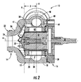
図1と図2は、血液等を送るのに利用される渦巻きポンプ10を図示する。ポンプ10は、両側に提供されている第1端14と第2端16とを備え、中心軸Aを有したポンプハウジング12を含む。
1 and 2 illustrate a
図示の実施例では、ポンプハウジング12は、本体18と別体のカバープレート20とに分割される。カバープレート20は、第2端16を閉鎖し、固定手段によって本体18に固定されている。
In the illustrated embodiment, the
ポンプハウジング12の中央部は、略円筒形である。ポンプハウジング12の第1端14は、内在通路24を含んだ従来形状である中央軸整合状態のインレット22と略錐形部26とを有している。
The central part of the
カバープレート20と一体であるステータ(固定子)ハウジング28は、カバープレート20からポンプハウジング12の中央にまで延びている。ステータハウジング28の先端は、錐形面30を提供する。複数のコイル巻部を含む電気ステータ32は、ステータハウジング28の内部に収容されている。カバープレート20を貫通するケーブル34は、ステータ32に電力、制御およびセンサー機能のための電気接続を提供する。
A stator (stator) housing 28 integral with the
ロータ(回転子)36がポンプハウジング12内に配置され、ステータハウジング28を包囲している。ロータ36は、略円筒形であり、第1端部38と第2端部40は、ポンプハウジング12の第1端14と第2端16に対応する。ロータ36は、第1端部38にプライマリインペラ41を含む。これは、インレット22と錐形面30との間に位置する環状アレイ形態の羽根を含む。プライマリインペラ41の羽根の外側先端は、一般的にインペラ平面内に存在する。イン
ペラ平面は、図2において“P”で示されている。永久磁石42がロータ36の壁部内で環状アレイ内に配置されている。環状アレイの羽根を含んだセカンダリ(二次)インペラ44は、ロータ36の第2端部40に配置されている。ロータ36とステータ32は、従来式にケーブル34を通じたステータ32への変動電流の適用を通してブラシレスDCモータとして機能する。
A rotor (rotor) 36 is disposed in the
ポンプハウジング12とロータ36とを含んだ、血液または組織と接触するポンプ10の全部材は、チタン、医療品質ポリマー、等々の知られた生物学的適応材料により製作される。
All components of
ステータハウジング28とロータ36は共同で、作動中のロータ36のための流体力学ベアリングとして機能するように設計されている。特にセカンダリインペラ44は、プライマリインペラ41を流れる少量の血液を軸方向に流してカバープレート20に送り、放射内側方向にセカンダリインペラ44を通して流し、ロータ36とステータハウジング28との間でプライマリインペラ41側へ軸方向に流す。このベアリングと再循環機能は、ホルバス他のUS特許7189260にてさらに詳細に解説されている。
The
ポンプハウジング12は、プライマリインペラ41から流出する流体を回収し、1つのアウトレット46(図1)へと送る環状通路を含む。この通路は、“ボリュート”またはボリュートハウジング48と呼称される。図2で示すようにボリュートハウジング48の軸位置は、プライマリインペラ41の平面Pからカバープレート20側にオフセットされている。
The
インペラ平面Pとボリュートハウジング48の中央面“V”との間の距離“D”である実際のオフセット距離は、決定的に重要な寸法ではないが、一般的には、ボリュートハウジング48は、ポンプハウジング12およびボリュートハウジング48の壁部の物理的制約範囲内でカバープレート20側に可能な限り大きくオフセットされる。図示の実施例では、ボリュートハウジング48の中央面Vは、インペラ平面Pとポンプハウジング12の第2端16とのほぼ中間に位置する。
The actual offset distance, which is the distance “D” between the impeller plane P and the central plane “V” of the
ボリュートハウジング48のこの配置は、従来の渦巻きポンプのデザインとは対照的である。例えば図3は、ポンプハウジング112、プライマリインペラ141およびボリュートハウジング148を有した従来の渦巻きポンプ110を図示する。ボリュートハウジング148とプライマリインペラ141の羽根の外側先端は、1面“P”で実質的に整合されている。
This arrangement of the
驚くことにボリュートハウジング48のオフセット位置は、ポンプ10の作動中の流体滞留時間を大きく短縮させることが発見された。この“滞留時間”とは、インレット22に入ってからアウトレット46から出るまで、特定の決定可能な体積の流体がポンプ10内に滞在する時間のことである。滞留時間は、平均質量や体積流量に必ずしも関係しない。例えば、従来ポンプ110は、比較的に長い滞留時間を示すであろう。流体の可視化試験によってポンプ10内の最長滞留時間は、従来ポンプ110の最長滞留時間と較べて約半分に短縮されることが発見された。
Surprisingly, it has been discovered that the offset position of the
従来とは異なる配置にも拘わらず全体的なポンプ性能は、その作動範囲に亘って維持される。ポンプ10のメカニカルな効率もボリュートハウジング48を動かすことで実質的に変更なく維持される。
Despite the different arrangement, the overall pump performance is maintained over its operating range. The mechanical efficiency of the
ポンプ10をLVADまたはRVADである心室補助システムのための埋め込み型血液ポンプとして使用するとき滞留時間の短縮は特に有利である。なぜなら血栓(凝結)形成および溶血(赤血球損傷)を回避するために血液の滞留時間を最短にすることが望まれるからである。しかしながら、ここで解説する概念は、作用流体が全血、血漿、血清あるいは複合分子を含む他の治療用流体のごとき、せん断およびメカニカル損傷に対して敏感であるような他の流体送達形態であっても有効である。
Reduction of residence time is particularly advantageous when the
以上、渦巻きポンプを解説した。本発明の特定の実施例を解説したが、本発明の精神と範囲とから逸脱せずにそれら実施例に様々な変更を加えることが可能であることを専門家であれば理解するであろう。従って、上述は、本発明の好適実施例の説明であり、本発明の説明のみを目的として提供されており、本発明の限定は意図されていない。 This completes the description of the centrifugal pump. While specific embodiments of the present invention have been described, those skilled in the art will appreciate that various modifications can be made to these embodiments without departing from the spirit and scope of the present invention. . Accordingly, the foregoing is a description of the preferred embodiment of the present invention and is provided for the purpose of illustrating the present invention only and is not intended to be limiting.
Claims (10)
(a)第1端と第2端とを有したポンプハウジングと、
(b)1軸周囲で回転するように前記ポンプハウジング内に配置され、かつ、略円筒形のロータの第1端部に取り付けられているプライマリインペラであって、それら外側先端部が共にインペラ平面を形成している複数の羽根を含んでいるプライマリインペラと、
(c)前記ロータの第2端部に取り付けられているセカンダリインペラであって、当該ポンプを通して流体を再循環するセカンダリインペラと、
(d)前記プライマリインペラと通流状態に設置されているインレットと、
(e)前記プライマリインペラおよびアウトレットと連絡状態である環状ボリュートハウジングであって、前記インペラ平面とは、軸方向にオフセットされており、かつ、軸方向において前記プライマリインペラと前記セカンダリインペラとの間に配置されている環状ボリュートハウジングと、
を含んでいることを特徴とするポンプ。 A blood pump,
(A) a pump housing having a first end and a second end,
(B) A primary impeller which is disposed in the pump housing so as to rotate around one axis and is attached to a first end portion of a substantially cylindrical rotor, both outer tip portions of which are impeller planes A primary impeller including a plurality of blades forming
(C) a secondary impeller attached to the second end of the rotor, wherein the secondary impeller recirculates fluid through the pump;
( D ) an inlet installed in flow with the primary impeller;
(E) a said primary impeller and outlet and contact state der Ru annular volute housing, with the impeller plane is offset in the axial direction and, between the axial direction and the primary impeller and the secondary impeller An annular volute housing disposed on the
A pump characterized by containing.
(b)前記ロータは、少なくとも1つの磁石を内在させている、
ことを特徴とする請求項2記載のポンプ。 (A) the coil winding part of the electric stator is accommodated in the stator housing,
(B) the rotor contains at least one magnet;
The pump according to claim 2 .
(a)第1端と第2端とを有したポンプハウジングと、
(b)1軸周囲で回転するように前記ポンプハウジング内に配置され、かつ、略円筒形のロータの第1端部に取り付けられているプライマリインペラであって、それら外側先端部が共にインペラ平面を形成している複数の羽根を含んでいるプライマリインペラと、
(c)前記ロータの第2端部に取り付けられているセカンダリインペラであって、ポンプを通して流体を再循環するセカンダリインペラと、
(d)前記プライマリインペラと通流状態に設置されているインレットと、
(e)前記プライマリインペラおよびアウトレットと連絡状態である環状ボリュートハウジングであって、前記インペラ平面とは、軸方向に離れており、かつ、軸方向において前記プライマリインペラと前記セカンダリインペラとの間に配置されている環状ボリュートハウジングと、
を含んでおり、
前記ポンプハウジング、前記プライマリインペラ、前記セカンダリインペラ、前記インレットおよび前記ボリュートハウジングは、生物学的適合材料で製作されていることを特徴とする心臓補助装置。 A cardiac assist device,
(A) a pump housing having a first end and a second end,
(B) A primary impeller which is disposed in the pump housing so as to rotate around one axis and is attached to a first end portion of a substantially cylindrical rotor, both outer tip portions of which are impeller planes A primary impeller including a plurality of blades forming
(C) a secondary impeller attached to the second end of the rotor, wherein the secondary impeller recirculates fluid through the pump;
( D ) an inlet installed in flow with the primary impeller;
(E) said a primary impeller and outlet and contact state der Ru annular volute housing, with the impeller plane is spaced axially and, between the secondary impeller and the primary impeller in the axial direction An annular volute housing being disposed ;
Contains
The cardiac assist device, wherein the pump housing, the primary impeller, the secondary impeller, the inlet, and the volute housing are made of a biocompatible material.
(b)前記ロータは、少なくとも1つの磁石を内在させている、
ことを特徴とする請求項7記載の心臓補助装置。 (A) the coil winding part of the electric stator is accommodated in the stator housing,
(B) the rotor contains at least one magnet;
The cardiac assist device according to claim 7, wherein:
Applications Claiming Priority (3)
| Application Number | Priority Date | Filing Date | Title |
|---|---|---|---|
| US12/336,283 | 2008-12-16 | ||
| US12/336,283 US8517699B2 (en) | 2008-12-16 | 2008-12-16 | Centrifugal pump with offset volute |
| PCT/US2009/067427 WO2010074979A1 (en) | 2008-12-16 | 2009-12-10 | Centrifugal pump with offset volute |
Publications (2)
| Publication Number | Publication Date |
|---|---|
| JP2012512363A JP2012512363A (en) | 2012-05-31 |
| JP5653932B2 true JP5653932B2 (en) | 2015-01-14 |
Family
ID=42240765
Family Applications (1)
| Application Number | Title | Priority Date | Filing Date |
|---|---|---|---|
| JP2011542258A Expired - Fee Related JP5653932B2 (en) | 2008-12-16 | 2009-12-10 | Centrifugal pump with offset volute |
Country Status (6)
| Country | Link |
|---|---|
| US (1) | US8517699B2 (en) |
| EP (1) | EP2359007B1 (en) |
| JP (1) | JP5653932B2 (en) |
| CN (1) | CN102257279B (en) |
| BR (1) | BRPI0922907A2 (en) |
| WO (1) | WO2010074979A1 (en) |
Families Citing this family (36)
| Publication number | Priority date | Publication date | Assignee | Title |
|---|---|---|---|---|
| US9782527B2 (en) | 2009-05-27 | 2017-10-10 | Tc1 Llc | Monitoring of redundant conductors |
| US8562508B2 (en) | 2009-12-30 | 2013-10-22 | Thoratec Corporation | Mobility-enhancing blood pump system |
| TW201217010A (en) | 2010-06-22 | 2012-05-01 | Thoratec Corp | Apparatus and method for modifying pressure-flow characteristics of a pump |
| WO2012012552A1 (en) | 2010-07-22 | 2012-01-26 | Thoratec Corporation | Controlling implanted blood pumps |
| USD669585S1 (en) * | 2010-08-20 | 2012-10-23 | Thoratec Corporation | Implantable blood pump |
| US9091271B2 (en) | 2010-08-20 | 2015-07-28 | Thoratec Corporation | Implantable blood pump |
| AU2011305250B2 (en) | 2010-09-24 | 2014-10-02 | Thoratec Corporation | Generating artificial pulse |
| WO2013056131A1 (en) | 2011-10-13 | 2013-04-18 | Reichenbach Steven H | Pump and method for mixed flow blood pumping |
| AU2012345572C1 (en) * | 2011-12-03 | 2018-05-31 | Indiana University Research And Technology Corporation | Cavopulmonary viscous impeller assist device and method |
| WO2013134319A1 (en) | 2012-03-05 | 2013-09-12 | Justin Aron Callaway | Modular implantable medical pump |
| EP2890419B1 (en) | 2012-08-31 | 2019-07-31 | Tc1 Llc | Start-up algorithm for an implantable blood pump |
| US9579436B2 (en) | 2012-08-31 | 2017-02-28 | Thoratec Corporation | Sensor mounting in an implantable blood pump |
| CN106456853B (en) | 2014-04-15 | 2019-04-23 | Tc1有限责任公司 | For controlling the method and system of blood pump |
| EP3131600B1 (en) | 2014-04-15 | 2021-06-16 | Tc1 Llc | Methods and systems for providing battery feedback to patient |
| WO2015160995A1 (en) | 2014-04-15 | 2015-10-22 | Thoratec Corporation | Ventricular assist devices |
| WO2015160994A1 (en) | 2014-04-15 | 2015-10-22 | Thoratec Corporation | Methods and systems for upgrading ventricle assist devices |
| US9744280B2 (en) | 2014-04-15 | 2017-08-29 | Tc1 Llc | Methods for LVAD operation during communication losses |
| CN103977464B (en) * | 2014-06-06 | 2016-08-17 | 清华大学 | A kind of implantable micro-axial blood pump of exit gradual change flow region |
| US10724534B2 (en) | 2014-11-26 | 2020-07-28 | Tc1 Llc | Pump and method for mixed flow blood pumping |
| EP3313471A4 (en) | 2015-06-29 | 2019-02-20 | Tc1 Llc | Ventricular assist devices having a hollow rotor and methods of use |
| WO2017015268A1 (en) | 2015-07-20 | 2017-01-26 | Thoratec Corporation | Flow estimation using hall-effect sensors |
| EP3324840A4 (en) | 2015-07-20 | 2019-03-20 | Tc1 Llc | Strain gauge for flow estimation |
| US11045639B2 (en) | 2015-10-29 | 2021-06-29 | The Cleveland Clinic Foundation | Ventricular assist device with pulse augmentation and automatic regurgitant flow shutoff |
| EP3165242B1 (en) * | 2015-11-05 | 2019-05-15 | ReinHeart GmbH | Fluid pump with volute shaped housing |
| EP3222301B1 (en) * | 2016-03-23 | 2018-05-09 | Abiomed Europe GmbH | Blood pump |
| US10857273B2 (en) | 2016-07-21 | 2020-12-08 | Tc1 Llc | Rotary seal for cantilevered rotor pump and methods for axial flow blood pumping |
| WO2018031741A1 (en) | 2016-08-12 | 2018-02-15 | Tc1 Llc | Devices and methods for monitoring bearing and seal performance |
| WO2018081505A1 (en) * | 2016-10-28 | 2018-05-03 | Heartware, Inc. | Single-piece volute |
| CN107050543B (en) * | 2017-05-04 | 2023-07-04 | 浙江理工大学 | Microminiature centrifugal blood pump with self-adjusting blades |
| EP3634528B1 (en) | 2017-06-07 | 2023-06-07 | Shifamed Holdings, LLC | Intravascular fluid movement devices, systems, and methods of use |
| CN111556763B (en) | 2017-11-13 | 2023-09-01 | 施菲姆德控股有限责任公司 | Intravascular fluid movement device and system |
| US10973967B2 (en) | 2018-01-10 | 2021-04-13 | Tc1 Llc | Bearingless implantable blood pump |
| EP4085965A1 (en) | 2018-02-01 | 2022-11-09 | Shifamed Holdings, LLC | Intravascular blood pumps and methods of use and manufacture |
| US11964145B2 (en) | 2019-07-12 | 2024-04-23 | Shifamed Holdings, Llc | Intravascular blood pumps and methods of manufacture and use |
| US11654275B2 (en) | 2019-07-22 | 2023-05-23 | Shifamed Holdings, Llc | Intravascular blood pumps with struts and methods of use and manufacture |
| US11724089B2 (en) | 2019-09-25 | 2023-08-15 | Shifamed Holdings, Llc | Intravascular blood pump systems and methods of use and control thereof |
Family Cites Families (14)
| Publication number | Priority date | Publication date | Assignee | Title |
|---|---|---|---|---|
| US5049134A (en) * | 1989-05-08 | 1991-09-17 | The Cleveland Clinic Foundation | Sealless heart pump |
| DE69011731T2 (en) * | 1989-05-19 | 1995-03-16 | Vickers Inc | Pump. |
| DE4315448A1 (en) * | 1992-05-19 | 1993-12-23 | Lederle Pumpen & Maschf | Peripheral wheel or turbine pump - has flow feed path using centrifugal impeller components and guide elements. |
| DE19625300A1 (en) * | 1996-06-25 | 1998-01-02 | Guenter Prof Dr Rau | Blood pump |
| EP0900572B1 (en) * | 1997-09-04 | 2005-01-12 | Levitronix LLC | Centrifugal pump |
| AT412065B (en) * | 2000-03-24 | 2004-09-27 | Schima Heinrich Dr | ROTATIONAL PUMP WITH HYDRAULICALLY BEARED ROTOR |
| EP1267959B1 (en) | 2000-03-27 | 2005-06-15 | The Cleveland Clinic Foundation | Ventricular assist system with secondary impeller |
| CN2606202Y (en) * | 2003-03-10 | 2004-03-10 | 宜兴市宙斯泵业有限公司 | Improved two-stage centrifugal pumps |
| WO2005073560A1 (en) * | 2004-01-30 | 2005-08-11 | Pax Scientific, Inc | A vortical flow rotor |
| DE102004019721A1 (en) * | 2004-03-18 | 2005-10-06 | Medos Medizintechnik Ag | pump |
| US7972122B2 (en) | 2005-04-29 | 2011-07-05 | Heartware, Inc. | Multiple rotor, wide blade, axial flow pump |
| US7699586B2 (en) | 2004-12-03 | 2010-04-20 | Heartware, Inc. | Wide blade, axial flow pump |
| US8419609B2 (en) | 2005-10-05 | 2013-04-16 | Heartware Inc. | Impeller for a rotary ventricular assist device |
| US7704054B2 (en) | 2006-04-26 | 2010-04-27 | The Cleveland Clinic Foundation | Two-stage rotodynamic blood pump |
-
2008
- 2008-12-16 US US12/336,283 patent/US8517699B2/en active Active
-
2009
- 2009-12-10 EP EP09835522.5A patent/EP2359007B1/en not_active Not-in-force
- 2009-12-10 BR BRPI0922907A patent/BRPI0922907A2/en not_active IP Right Cessation
- 2009-12-10 JP JP2011542258A patent/JP5653932B2/en not_active Expired - Fee Related
- 2009-12-10 WO PCT/US2009/067427 patent/WO2010074979A1/en active Application Filing
- 2009-12-10 CN CN200980150952.9A patent/CN102257279B/en not_active Expired - Fee Related
Also Published As
| Publication number | Publication date |
|---|---|
| EP2359007A4 (en) | 2015-03-04 |
| JP2012512363A (en) | 2012-05-31 |
| EP2359007A1 (en) | 2011-08-24 |
| US8517699B2 (en) | 2013-08-27 |
| BRPI0922907A2 (en) | 2018-05-29 |
| US20100150749A1 (en) | 2010-06-17 |
| CN102257279A (en) | 2011-11-23 |
| WO2010074979A1 (en) | 2010-07-01 |
| EP2359007B1 (en) | 2019-03-13 |
| CN102257279B (en) | 2016-03-23 |
Similar Documents
| Publication | Publication Date | Title |
|---|---|---|
| JP5653932B2 (en) | Centrifugal pump with offset volute | |
| JP3012308B2 (en) | Disposable pump action unit | |
| US7972122B2 (en) | Multiple rotor, wide blade, axial flow pump | |
| US7699586B2 (en) | Wide blade, axial flow pump | |
| JP5442598B2 (en) | Centrifugal rotary blood pump | |
| JP5973564B2 (en) | Heart pump | |
| JP4534073B2 (en) | Secondary impeller of ventricular assist system | |
| EP3436104B1 (en) | Crenellated inflow cannula | |
| WO2014019274A1 (en) | Single-fulcrum magnetomotive centrifugal blood pump | |
| US20180335037A1 (en) | Center rod magnet | |
| US11686318B2 (en) | Centrifugal blood pump device | |
| WO2012150045A2 (en) | Blood pump | |
| EP3393542B1 (en) | Axial flow implantable mechanical circulatory support devices with outlet volute | |
| US20230414924A1 (en) | Rotary blood pump | |
| CN108785770A (en) | A kind of external blood pump that can reduce haemolysis | |
| CN111375098B (en) | Percutaneous blood pump and rotor limit structure thereof | |
| JP3247718B2 (en) | Blood pump | |
| US20230381489A1 (en) | Implantable centrifugal cardiac assist pump having permanent magnets embedded in impeller | |
| JP3247716B2 (en) | Blood pump | |
| JP2001054568A (en) | Blood pump | |
| JPS628182B2 (en) | ||
| JP2001252351A (en) | Blood pump |
Legal Events
| Date | Code | Title | Description |
|---|---|---|---|
| A621 | Written request for application examination |
Free format text: JAPANESE INTERMEDIATE CODE: A621 Effective date: 20121205 |
|
| A977 | Report on retrieval |
Free format text: JAPANESE INTERMEDIATE CODE: A971007 Effective date: 20131128 |
|
| A131 | Notification of reasons for refusal |
Free format text: JAPANESE INTERMEDIATE CODE: A131 Effective date: 20131203 |
|
| A601 | Written request for extension of time |
Free format text: JAPANESE INTERMEDIATE CODE: A601 Effective date: 20140224 |
|
| A602 | Written permission of extension of time |
Free format text: JAPANESE INTERMEDIATE CODE: A602 Effective date: 20140303 |
|
| A601 | Written request for extension of time |
Free format text: JAPANESE INTERMEDIATE CODE: A601 Effective date: 20140401 |
|
| A602 | Written permission of extension of time |
Free format text: JAPANESE INTERMEDIATE CODE: A602 Effective date: 20140408 |
|
| A521 | Request for written amendment filed |
Free format text: JAPANESE INTERMEDIATE CODE: A523 Effective date: 20140425 |
|
| TRDD | Decision of grant or rejection written | ||
| A01 | Written decision to grant a patent or to grant a registration (utility model) |
Free format text: JAPANESE INTERMEDIATE CODE: A01 Effective date: 20141028 |
|
| A61 | First payment of annual fees (during grant procedure) |
Free format text: JAPANESE INTERMEDIATE CODE: A61 Effective date: 20141119 |
|
| R150 | Certificate of patent or registration of utility model |
Ref document number: 5653932 Country of ref document: JP Free format text: JAPANESE INTERMEDIATE CODE: R150 |
|
| R250 | Receipt of annual fees |
Free format text: JAPANESE INTERMEDIATE CODE: R250 |
|
| R250 | Receipt of annual fees |
Free format text: JAPANESE INTERMEDIATE CODE: R250 |
|
| R250 | Receipt of annual fees |
Free format text: JAPANESE INTERMEDIATE CODE: R250 |
|
| R250 | Receipt of annual fees |
Free format text: JAPANESE INTERMEDIATE CODE: R250 |
|
| LAPS | Cancellation because of no payment of annual fees |