JP5651326B2 - Beverage container closure - Google Patents
Beverage container closure Download PDFInfo
- Publication number
- JP5651326B2 JP5651326B2 JP2009267641A JP2009267641A JP5651326B2 JP 5651326 B2 JP5651326 B2 JP 5651326B2 JP 2009267641 A JP2009267641 A JP 2009267641A JP 2009267641 A JP2009267641 A JP 2009267641A JP 5651326 B2 JP5651326 B2 JP 5651326B2
- Authority
- JP
- Japan
- Prior art keywords
- locking
- lid
- piece
- container
- opening
- Prior art date
- Legal status (The legal status is an assumption and is not a legal conclusion. Google has not performed a legal analysis and makes no representation as to the accuracy of the status listed.)
- Expired - Fee Related
Links
Images


Description
本発明は、携帯用の飲料容器における栓体に関するものである。 The present invention relates to a stopper in a portable beverage container.
携帯用の飲料容器は、容器本体と、容器本体の開口部に装着される栓体と、更に前記栓体を覆うように装着されるキャップ体とで構成されるものが知られており、近年において容器本体は、ステンレス製の真空断熱二重容器が採用され、栓体は、流出路を下方(容器内)から閉塞する弁体を備えた構造(特開平8−289849号)や、流出路の洗浄が容易になるように流出路の上方から閉塞する構造のものが採用されている。 A portable beverage container is known which is composed of a container body, a stopper attached to the opening of the container body, and a cap attached to cover the stopper. The container body employs a vacuum insulated double container made of stainless steel, and the stopper has a structure (Japanese Patent Laid-Open No. 8-289849) having a valve body that closes the outflow path from below (inside the container), or an outflow path. The structure of closing from the upper part of the outflow path is adopted so that the washing of the water becomes easy.
注出口(流出路内周面又は底面)を上方から閉塞する栓体は、容器本体の開口部に装着し、注出口を有する流出路部を設けた下筒体と、流出路部内に侵入して注出口該当箇所を塞ぐ栓部を備え、下筒体に煽り回動自在にヒンジ連結した蓋体とで構成しているものである。 The plug that closes the spout (outlet channel inner peripheral surface or bottom surface) from above is installed in the opening of the container body, and enters the outflow channel with the lower cylinder provided with the outflow channel having the spout. And a lid that is provided with a plug portion that closes the corresponding portion of the spout and is hinged to the lower cylinder so as to be freely pivoted.
また前記の蓋体は、閉口時には注出口からの水漏れが発生しないように何らかの係止構造を備えて閉口状態を維持し、且つ容器本体内飲料を注ぎ出す際には、蓋体が開口状態を維持する必要があり、而も前記の閉口状態においては、キャップ体が装着される構造でなければならない。即ち栓体は、所定の空間内に収まる大きさで、開口付勢構造と閉口時の係止構造を備える必要がある。 The lid body is provided with some kind of locking structure so that water leakage from the spout does not occur when the lid is closed, and when the beverage in the container body is poured out, the lid body is in an open state. In the closed state, the cap body must be attached. That is, the plug body needs to have a size that fits within a predetermined space, and has an opening urging structure and a locking structure when the mouth is closed.
前記の構造を備えた従来手段として、特許文献1(特開2001−149235号公報)に、ヒンジ軸と直交する方向にスライド移動すると共に、先方(ヒンジ軸位置を基方と定義する)に付勢した係止体を、蓋体上面に設け、下筒体の流出路部の先方内周面に、係止受け凹部を設け、前記係止体に前記係止受け凹部に係止される係止爪を設けてなる係止構造が開示されている。 As conventional means having the above-described structure, Patent Document 1 (Japanese Patent Application Laid-Open No. 2001-149235) slides in a direction orthogonal to the hinge axis and attaches to the tip (defining the hinge axis position as the base). The latched body is provided on the upper surface of the lid, a latch receiving recess is provided on the front inner peripheral surface of the outflow passage of the lower cylinder, and the latch is locked to the latch receiving recess. A locking structure provided with a pawl is disclosed.
更に特許文献2(特開2008−137657号公報)には、下筒体の流出路部の上縁側方個所に係止鉤部を形成し、係止体の両側方個所にL状の係止爪を設けてなる係止構造が開示されている。 Further, in Patent Document 2 (Japanese Patent Laid-Open No. 2008-137657), a locking collar portion is formed at an upper edge side portion of the outflow passage portion of the lower cylindrical body, and an L-shaped locking portion is provided at both side portions of the locking body. A locking structure provided with a claw is disclosed.
第一の課題として、前記のとおりキャップ体を備えた飲料用容器における煽り回動による開閉機構を備えた蓋体を有する栓体では、開口付勢構造と閉口時の係止構造を備えると共に、所定の空間内に収まる大きさに形成する必要がある。このため特許文献1で開示されている係止構造は、係止受け凹部を流出路部の先方内周面に形成しているために、容器本体内の飲料が流出する際に当該凹部の形成個所を流れるので、注出流に乱れが生ずると共に、当該個所が凹部であるために汚れも沈着し易い。 As a first problem, as described above, the plug body having a lid body having an opening and closing mechanism by turning in a beverage container having a cap body includes an opening biasing structure and a locking structure at the time of closing, It is necessary to form a size that fits within a predetermined space. For this reason, since the latching structure currently disclosed by patent document 1 forms the latch receiving recessed part in the front inner peripheral surface of an outflow channel part, when the drink in a container main body flows out, formation of the said recessed part is formed. Since it flows through the place, the discharge flow is disturbed, and since the place is a recess, dirt is easily deposited.
また特許文献2に開示されているように、下筒体の流出路部の上縁側方個所に係止鉤部を形成している場合には、係止個所とヒンジ軸との距離が近いために、係止当接個所が受ける圧力(開口方向の付勢力)が大きく、不測の係止解除が為されないように、係止鉤と係止爪の係止形状を考慮する必要があり、且つ充分な係止面積が必要となり、前記の配慮を為すと係止解除の抵抗力が大きくなり、逆に係止解除の操作性を損なうことになる。このように前記構造は、相反する条件を備える構造であり、必ずしも最適な係止構造とは言えない。
In addition, as disclosed in
また第二の課題として、前記の前後スライド構造の係止体を採用した場合には、係止体の移動操作方向と、蓋体の動作方向が相違するので、開口操作性に問題がある。 Further, as a second problem, when the locking body having the front and rear slide structure is employed, there is a problem in opening operability because the moving operation direction of the locking body is different from the operation direction of the lid.
即ち係止体は、係止状態を維持するために係止方向(先方向)に付勢されており、係止解除を行うには、前記の先方向付勢力に抗って指で係止体をスライド操作し、その状態で係止体から指を離すと、蓋体は上方へ煽り回動するが、同時に係止体も先方にスライド復帰移動するので、確実な蓋体開口操作には、係止体を後方にスライドさせた状態を維持しながら、指による蓋体への下圧力を小さくするという操作が必要になり、単純な操作での確実な開口が必ずしも実現するものではない。 That is, the locking body is urged in the locking direction (forward direction) in order to maintain the locked state. To release the locking, the locking body is locked with a finger against the forward biasing force. When the body is slid and the finger is released from the locking body in that state, the lid body turns up and rotates, but at the same time, the locking body also slides back to the front, so that the lid opening operation is reliable. While maintaining the state in which the locking body is slid rearward, an operation of reducing the downward pressure on the lid by the finger is required, and a reliable opening with a simple operation is not necessarily realized.
更に第三の課題として、前記の係止構造において係止体の動作抑止は、係止体に付設した付勢機構のみであるので、誤って係止体を動作させてしまった場合に、内部飲料が零れてしまう虞があり、また蓋体の確実な閉塞を確認せずにキャップ体を装着して携帯した場合に、携帯時に内部飲料が漏れてしまう虞がある。 Further, as a third problem, in the above-described locking structure, since the operation of the locking body is restricted only by the urging mechanism attached to the locking body, if the locking body is accidentally operated, There is a risk that the beverage will spill, and when the cap body is attached without carrying out the reliable closure of the lid body, the internal beverage may leak when being carried.
そこで本発明は、前記の課題を解決する新規な飲料用容器の栓体を提案したものである。 Therefore, the present invention proposes a novel beverage container stopper that solves the above-mentioned problems.
本発明(請求項1)に係る飲料用容器の栓体は、容器本体の開口部に装着され、容器本体の開口部への装着筒部、及び注出口を有する抽出筒部を設けた下筒体と、前記注出筒部内に侵入して注出口該当箇所を塞ぐ栓部を備え、下筒体に煽り回動自在にヒンジ軸で連結すると共に開口方向に付勢した蓋体とで構成してなる飲料用容器の栓体において、下筒体におけるヒンジ軸と反対側となる流出路部の外周面に係止受け部を形成し、前記係止受け部と対応する個所に係止爪を設けた係止片部、及び蓋体上面に位置する操作片部とを有した全体逆さL状の係止体を、逆さL状における角部位置でヒンジ軸と略平行な支軸で軸支し、且つ前記操作片部を蓋体上面に露出させて揺動自在に蓋体に組み込み、前記操作片部の蓋体上面方向からの押圧操作によって、係止爪が係止受け部に対して係合離脱可能で、且つ係止爪を係止受け部方向に付勢する付勢部を付設した蓋体係止構造を備えてなると共に、前記係止体の操作片部を、係止片部と一体の揺動部と、前記揺動部上で前後方向に移動可能に設けた移動部とで形成し、移動部先端面が係止片部外周と一致する際に、移動部の基方が蓋体上面と当接して係止体の揺動動作を阻止し、移動部の前方突出で揺動を可能としたロック機構を設けてなることを特徴とするものである。 A stopper for a beverage container according to the present invention (Claim 1) is attached to an opening of a container body, and a lower cylinder provided with an attachment cylinder part to the opening of the container body and an extraction cylinder part having a spout And a lid body that has a plug portion that penetrates into the dispensing tube portion and closes the corresponding portion of the dispensing port, is pivotably connected to the lower tube body by a hinge shaft, and is biased in the opening direction. In the stopper of the beverage container, a latch receiving portion is formed on the outer peripheral surface of the outflow passage portion on the opposite side of the hinge shaft in the lower cylinder, and a locking claw is provided at a position corresponding to the latch receiving portion. The entire inverted L-shaped locking body having the provided locking piece portion and the operation piece portion located on the upper surface of the lid is pivotally supported by a support shaft that is substantially parallel to the hinge shaft at the corner position in the inverted L shape. and, and the operation lever portion exposed to the lid top surface embedded in lid swingably, pressed from the lid top surface direction of the operation lever portion Accordingly, the engagement pawl can engage withdrawal against engaging portions, with and formed by a lid body engaging structure annexed a biasing unit that biases the locking pawl into the latch receiving portion direction The operating piece portion of the locking body is formed by a swinging portion integral with the locking piece portion and a moving portion provided on the swinging portion so as to be movable in the front-rear direction. Provided with a lock mechanism that allows the base of the moving part to come into contact with the upper surface of the lid when it coincides with the outer periphery of the stopper, preventing the locking body from swinging and allowing the swinging of the moving part to protrude forward It is characterized by.
而して蓋体を回動して栓部で注出口を閉塞して、係止体の係止爪が係止受け部に係止することで蓋体による閉口状態が維持され、係止体の係止爪と係止受け部との係合を解除すると、蓋体は回動付勢力によって回動して開口状態となる。 Thus, the lid is rotated and the spout is closed by the stopper, and the locking claw of the locking body is locked to the locking receiving portion so that the closed state by the lid is maintained. When the engagement between the locking claw and the locking receiving portion is released, the lid body is rotated by the rotation urging force to be in the open state.
従って下筒体の係止受け部が流出路部の外周に設けられているので、流出路部の洗浄に不都合が生じないし、また係止位置がヒンジ軸と離れた個所に存在するので、蓋体回動付勢力が強く作用せず、係止体の回動解除操作が容易になされる。 Therefore, since the latch receiving portion of the lower cylindrical body is provided on the outer periphery of the outflow passage portion, there is no inconvenience in cleaning the outflow passage portion, and the latching position exists at a location away from the hinge shaft. The body rotation biasing force does not act strongly, and the rotation release operation of the locking body is easily performed.
更に本発明は、係止体を、ヒンジ軸と略平行な支軸で軸支して揺動自在に組み込んでなるもので、係止体の操作片部を上方より下圧すると係止体が回動して係止状態が解除され、そのまま下圧を開放すると、蓋体は回動付勢力によって回動して開口状態となる。この係止体の係止解除回動操作時には、係止体の付勢力方向と、蓋体の開口回動付勢力方向が一致するので、係止体の解除状態で指での下圧を解除しても、蓋体の回動付勢力で係止体の操作片部が指先に当接して係止体の解除状態が維持されて蓋体が開口方向に回動を開始するので、開口動作が非常にスムーズになされるものである。またロック機構は、移動部の前後スライド移動でロック及びその解除をなすもので、移動部が後退して移動部先端面が係止片部外周と一致する状態(非突出状態)で、移動部基方が蓋体上面(ロック受け面)に当接して係止体の回動が阻止されてロック状態とし、移動部を前方に突出させると、移動部の基方がロック受け面上から移動して係止体が回動可能となり、係止体の操作によって開口することができるもので、このロック機構によって係止体の動作を制止しているものであるから、誤って係止体に操作方向の力が加わっても、誤って開口状状態となることが無い。 Further, according to the present invention, the locking body is pivotally supported by a support shaft that is substantially parallel to the hinge shaft, so that the locking body can be freely pivoted. When the locking state is released by rotating and the lower pressure is released as it is, the lid body is rotated by the rotating biasing force to be in the open state. During the unlocking rotation operation of the locking body, the biasing force direction of the locking body and the opening rotation biasing force direction of the lid body coincide with each other. Even so, the operating force of the lid body causes the operating piece of the locking body to come into contact with the fingertip and the released state of the locking body is maintained and the lid body starts to rotate in the opening direction. Is made very smoothly . The locking mechanism is a mechanism that locks and releases the sliding part by moving the moving part back and forth. The moving part moves backward, and the moving part tip surface is aligned with the outer periphery of the locking piece part (non-projecting state). When the base comes into contact with the upper surface of the lid (lock receiving surface) and the locking body is prevented from rotating, and the locked portion is brought into the locked state, and the moving portion protrudes forward, the base of the moving portion moves from the lock receiving surface. Since the locking body can be turned and can be opened by operating the locking body, the operation of the locking body is restrained by this locking mechanism. Even if a force in the operation direction is applied, there will be no accidental opening.
また本発明(請求項2)に係る飲料用容器の栓体は、係止体を蓋体に形成した凹部内に収めて、係止片部を蓋体の外周面と面一とし、且つ操作片部を蓋体上面と面一となるように設けてなると共に、移動部先端面が係止片部外周と一致する際のみに、容器本体に装着されるキャップ体内に納まるようにしてなるもので、係止体が蓋体の外周面及び上面と面一に形成することに相俟って、栓体の露出外形の突出部分が少なく、的確なキャップ体内収納が実現すると共に、すっきりとした外観を呈することになる。特に蓋体の開閉可能な状態(非ロック状態)では、移動部の突出によってキャップ体の装着ができないので、確実な閉口状態となってキャップ体が装着されるので、携帯時の内部飲料の漏れが生ずる虞が無い。 In the beverage container stopper according to the present invention (claim 2), the locking body is housed in a recess formed in the lid, the locking piece is flush with the outer peripheral surface of the lid, and the operation is performed. those with formed by providing a single part such that the lid top surface flush, only when the mobile front edge surface coincides with the engagement piece portion periphery becomes as fit the cap body to be attached to the container body In combination with the formation of the locking body flush with the outer peripheral surface and the upper surface of the lid body, there are few protruding parts of the exposed outer shape of the plug body, and accurate storage in the cap is realized, and it is neat The appearance will be exhibited. In particular, when the lid can be opened and closed (non-locked), the cap body cannot be attached due to the protrusion of the moving part, so the cap body is attached in a surely closed state. There is no risk of occurrence.
本発明の構成は上記のとおりで、流出路部の外周に係止構造を設けると共に、係止動作を行う係止体を所定の範囲内に収めて組み込んだもので、流出路内の洗浄に支障が生ずることがなく、係止効果の高いヒンジ軸と離れた位置での係止を実現でき、更に優れた開口操作性をも具備したものである。 The configuration of the present invention is as described above, and a locking structure is provided on the outer periphery of the outflow passage portion, and a locking body that performs the locking operation is accommodated within a predetermined range, and is used for cleaning the outflow passage. There is no hindrance, locking at a position away from the hinge shaft having a high locking effect can be realized, and further excellent opening operability is provided.
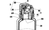
次に本発明の実施形態について説明する。実施形態に示した栓体は、所定の容器本体Aの開口部に装着され、且つ容器体本体Aに装着されるキャップ体B内に納まるものである。 Next, an embodiment of the present invention will be described. The plug body shown in the embodiment is installed in an opening of a predetermined container body A and fits in a cap body B attached to the container body A.
容器本体Aは、例えばステンレス製真空二重容器で、円筒状の容器部01の上部の開口部02の外周面にキャップ体Bの螺合用螺旋条03が形成され、内周面に栓体装着用の螺旋条04が形成されているものである。
The container body A is, for example, a stainless steel vacuum double container, and a screw thread 30 for the cap body B is formed on the outer peripheral surface of the
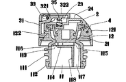
栓体は、下筒体1と、蓋体2と、蓋体2に組み込んだ係止体3で構成されるものである。
The plug is composed of a lower cylinder 1, a
下筒体1は、装着筒部11と、注出筒部(飲料容器が直飲タイプであれば、飲み口部となる)12と、被冠被覆部13を備えたもので、装着筒部11及び注出筒部12は、内部が連通して流出路が構成されるようにしたものである。
The lower cylindrical body 1 includes a mounting
装着筒部11は、容器本体Aの開口部02に螺合装着するように外周面に螺合突条111を形成し、下端に水封パッキン112を装着し、注出筒部12の間に狭搾部を形成して注出口113を設けると共に、前記注出口113に流出路を遮断するような横仕切り板114を形成し、前記横仕切り板114に基方流出口115と、先方流出口116を設け、基方流出口115の下方には、通路(空気路)117を形成する縦仕切り部118を設けてなるものである。
The mounting
注出筒部12は、注出口113からややフレア状に開口し、基方には、ヒンジ軸4を支持する軸支持部121を設け、先方に後述する係止爪34が係止される係止受け部122を設けたものである。
The dispensing
被冠被覆部13は、装着筒部11の上部外周に突出して、開口部01の開口端外周を覆うように設けたもので、キャップ体の螺合用螺条03より小径となるように形成されているものである。
The
蓋体2は、基方においてヒンジ軸4で前記注出筒部12の基方外周個所に軸結して、注出筒部12の上面を覆うように煽り回動自在に装着し、且つ前記軸結個所には、蓋体2が注出筒部12の上面を覆う方向(閉口方向)に付勢するバネ体を付設してなるものである。また蓋体の下面内側には、閉口時に注出口113を塞ぐ栓部21を垂設し、外周面22は、前記被冠被覆部13と面一になるように形成すると共に、前方部分及び上面部分には、係止体3が納まる凹部23を形成し、更に上面の凹部23においては、基方側に前記凹部23より少し高くしたロック受け面24を設けたものである。
The
係止体3は、前記凹部23に納まる大きさに形成したもので、縦の係止片部31と横の操作片部32からなり、全体が逆さL状で、角部をヒンジ軸4と略平行な支軸33で軸支して揺動自在に設けると共に、係止片部31の内側における係止受け部122に対応する個所に係止爪34を設け、前記係止爪34を係止受け部122方向に付勢する付勢部35を付設してなるものである。
The locking
また前記の操作片部32は、係止片部31と一体の揺動部321と、前記揺動部321上で前後方向に移動可能に設けた移動部322とで構成すると共に、前方移動によって移動部322の基端底面がロック受け面24の上面から外れ、後方移動によって前記基端底面がロック受け面24の直上に位置するように設けたものであり、係止片部31の外側面及び移動部322の後退時の先端面が、蓋体2の外周面と面一となるように形成され、移動部322の上面が、蓋体2の上面と面一となるように形成したものである。
The
而して前記の栓体は、容器本体Aの容器部01に所望の飲料を充填した後に、下筒体1の螺合突条111を容器本体Aの螺旋条04に螺合して、容器本体Aの開口部02に装着し、蓋体2を閉口ロック状態としてキャップ体Bを被せて携帯し、飲料を取り出す際に、キャップ体Bを外し、蓋体2を開口状態として、コップ兼用のキャップ体B等へ注出筒部12から飲料を注ぎ出し、喫飲に供するものである。
Thus, after filling the desired beverage in the
閉口状態について説明すると、図4に示すとおり、係止体3の係止爪34が係止受け部122に係止し、且つ付勢部35の付勢力で係止爪34が係止受け部122の方向に押し付けられているので、前記係止状態が維持されことになる。
The closed state will be described. As shown in FIG. 4, the locking
しかも前記閉口状態においては、係止体3の外周面(係止片部31の外側面及び移動部322の上面)が、蓋体2の外側面及び上面と面一となるので、栓体の露出外形において突出部が無く、キャップ体Bの着脱に全く支障が生じない。
Moreover, in the closed state, the outer peripheral surface of the locking body 3 (the outer surface of the
また前記閉口状態で、係止体3を動作させるべく、操作片部32(移動部322)を上方から押圧しても、移動部322の基方がロック受け面24に衝突して係止体の回動動作が阻止され、係止体3はロック状態となっているので、前記ロック状態を解除しない限り係止体3の回動動作が制止されており、誤って蓋体2が開口することが無い。
Further, even if the operating piece 32 (moving part 322) is pressed from above to operate the locking
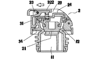
開口操作は、図5に示すように、移動部322を前方にスライド移動させて、移動部322の基方がロック受け面24上から離脱すると、係止体3の回動操作が可能となる。
As shown in FIG. 5, the opening operation is performed by sliding the moving
そして係止体3の操作片部(移動部の上面)32を下圧して係止体3を回動させると、係止爪34と係止受け部122の係止が解除され、そのまま下圧を解除すると、蓋体2は、開口方向の付勢力で開口動作するものである(図6,7)。
When the operating piece portion 32 (upper surface of the moving portion) 32 of the locking
特に前記の操作においては、係止体3の解除操作状態で、係止体3の付勢力と蓋体2の付勢力が同一方向で作用しているので、指での下圧を解除しても、解除直後においては、蓋体2の回動付勢力で係止体3の操作片部(移動部322)32が指先に当接しており、係止体3の解除状態が維持されて蓋体2の開口方向への回動が開始されることになり、開口動作が非常にスムーズになされる。
In particular, in the above-described operation, the urging force of the locking
また閉口する際には、蓋体2を閉口方向に回動操作して、係止体3の係止爪34を係止受け部122に係止して閉口するが、移動部322が前方へ突出した状態(非ロック状態)では、移動部322が邪魔になってキャップ体Bの装着ができない。従って移動部322をロック状態の位置まで操作移動させ、確実な閉口状態となってからキャップ体Bが装着されることになり、携帯時の内部飲料の漏れの生ずる虞が無い。
When closing the lid, the
1 下筒体
11 装着筒部
111 螺合突条
112 水封パッキン
113 注出口
114 横仕切り板
115 基方流出口
116 先方流出口
117 通路(空気路)
118 縦仕切り部
12 注出筒部
121 軸支持部
122 係止受け部
13 被冠被覆部
2 蓋体
21 栓部
22 外周面
23 凹部
24 ロック受け面
25 受け壁
3 係止体
31 係止片部
32 操作片部
321 揺動部
322 移動部
323 後壁部
33 支軸
34 係止爪
35 付勢部
4 ヒンジ軸
DESCRIPTION OF SYMBOLS 1
118
Claims (2)
Priority Applications (1)
| Application Number | Priority Date | Filing Date | Title |
|---|---|---|---|
| JP2009267641A JP5651326B2 (en) | 2009-11-25 | 2009-11-25 | Beverage container closure |
Applications Claiming Priority (1)
| Application Number | Priority Date | Filing Date | Title |
|---|---|---|---|
| JP2009267641A JP5651326B2 (en) | 2009-11-25 | 2009-11-25 | Beverage container closure |
Publications (3)
| Publication Number | Publication Date |
|---|---|
| JP2011111175A JP2011111175A (en) | 2011-06-09 |
| JP2011111175A5 JP2011111175A5 (en) | 2012-07-26 |
| JP5651326B2 true JP5651326B2 (en) | 2015-01-14 |
Family
ID=44233811
Family Applications (1)
| Application Number | Title | Priority Date | Filing Date |
|---|---|---|---|
| JP2009267641A Expired - Fee Related JP5651326B2 (en) | 2009-11-25 | 2009-11-25 | Beverage container closure |
Country Status (1)
| Country | Link |
|---|---|
| JP (1) | JP5651326B2 (en) |
Cited By (3)
| Publication number | Priority date | Publication date | Assignee | Title |
|---|---|---|---|---|
| USD896041S1 (en) | 2019-06-13 | 2020-09-15 | CamCal Enterprises, LLC | Container enclosure |
| USD896040S1 (en) | 2019-06-13 | 2020-09-15 | CamCal Enterprises, LLC | Container enclosure |
| US10773873B2 (en) | 2018-06-13 | 2020-09-15 | CamCal Enterprises, LLC | Beverage container enclosure |
Families Citing this family (8)
| Publication number | Priority date | Publication date | Assignee | Title |
|---|---|---|---|---|
| JP5263361B2 (en) | 2011-09-30 | 2013-08-14 | サーモス株式会社 | Beverage container closure |
| JP6123245B2 (en) * | 2012-11-14 | 2017-05-10 | タイガー魔法瓶株式会社 | Beverage container |
| JP5874716B2 (en) * | 2013-12-02 | 2016-03-02 | サーモス株式会社 | Beverage container closure |
| JP6509783B2 (en) * | 2016-06-10 | 2019-05-08 | サーモス株式会社 | Cap unit and container for beverage |
| JP6466387B2 (en) * | 2016-11-11 | 2019-02-06 | サーモス株式会社 | Cap unit and beverage container |
| CN106880247A (en) * | 2017-04-27 | 2017-06-23 | 美诗刻(昆山)家居用品有限公司 | Flip-over type water glass flip switch button mechanism |
| JP7090489B2 (en) * | 2018-06-26 | 2022-06-24 | サーモス株式会社 | Cap unit and container with cap |
| JP7364900B2 (en) | 2020-02-27 | 2023-10-19 | タイガー魔法瓶株式会社 | Stoppers and beverage containers |
Family Cites Families (7)
| Publication number | Priority date | Publication date | Assignee | Title |
|---|---|---|---|---|
| JPS4728405U (en) * | 1971-03-30 | 1972-12-01 | ||
| JPS61113243U (en) * | 1984-12-27 | 1986-07-17 | ||
| JPH0423502Y2 (en) * | 1989-06-21 | 1992-06-01 | ||
| JP2991130B2 (en) * | 1996-10-03 | 1999-12-20 | タイガー魔法瓶株式会社 | Liquid container stopper device |
| JP2003327265A (en) * | 2002-05-08 | 2003-11-19 | Tiger Vacuum Bottle Co Ltd | Container for carrying drink |
| JP4442819B2 (en) * | 2004-11-22 | 2010-03-31 | 象印マホービン株式会社 | Liquid container lid open / close button structure |
| JP5125157B2 (en) * | 2007-03-08 | 2013-01-23 | タイガー魔法瓶株式会社 | Open bottle |
-
2009
- 2009-11-25 JP JP2009267641A patent/JP5651326B2/en not_active Expired - Fee Related
Cited By (7)
| Publication number | Priority date | Publication date | Assignee | Title |
|---|---|---|---|---|
| US10773873B2 (en) | 2018-06-13 | 2020-09-15 | CamCal Enterprises, LLC | Beverage container enclosure |
| US10974889B2 (en) | 2018-06-13 | 2021-04-13 | CamCal Enterprises, LLC | Beverage container enclosure |
| US11505394B2 (en) | 2018-06-13 | 2022-11-22 | Bottlekeeper, Llc | Beverage container enclosure |
| US11952199B2 (en) | 2018-06-13 | 2024-04-09 | Bottlekeeper, Llc | Beverage container enclosure |
| USD896041S1 (en) | 2019-06-13 | 2020-09-15 | CamCal Enterprises, LLC | Container enclosure |
| USD896040S1 (en) | 2019-06-13 | 2020-09-15 | CamCal Enterprises, LLC | Container enclosure |
| USD927940S1 (en) | 2019-06-13 | 2021-08-17 | Bottlekeeper, Llc | Container enclosure |
Also Published As
| Publication number | Publication date |
|---|---|
| JP2011111175A (en) | 2011-06-09 |
Similar Documents
| Publication | Publication Date | Title |
|---|---|---|
| JP5651326B2 (en) | Beverage container closure | |
| JP2011111175A5 (en) | ||
| US10259620B2 (en) | Lid assembly for a container | |
| JP5125157B2 (en) | Open bottle | |
| JP5263361B2 (en) | Beverage container closure | |
| JP4798553B2 (en) | Beverage container | |
| CN109398927B (en) | Lid unit and beverage container | |
| JP5579802B2 (en) | Opening and closing mechanism for lid of portable beverage container | |
| JP2010235138A (en) | Bottle lid locking structure | |
| JP4970471B2 (en) | Gathering device for pouring free-flowing media out of the container | |
| JP2017007742A (en) | Cap unit and beverage container | |
| JP5105319B2 (en) | Beverage container closure | |
| JP2009219802A (en) | Locking device for lid of beverage or food container | |
| KR20200001478A (en) | Cap unit and Container with cap | |
| JP3178393U (en) | Beverage container closure | |
| JP6282070B2 (en) | Water bottle | |
| JP6466387B2 (en) | Cap unit and beverage container | |
| JP2013245006A (en) | Lid opening and closing locking mechanism for portable beverage container | |
| JP6458077B2 (en) | Beverage container closure | |
| CN216628152U (en) | Container cover capable of being opened by single hand | |
| CN209846776U (en) | Cup cover convenient for water outlet | |
| JP3177234U (en) | Beverage container closure | |
| JP3205245U (en) | Beverage container | |
| JP3171651U (en) | Beverage container stopper and beverage container having the same | |
| JP2011140355A (en) | Single swing bottle |
Legal Events
| Date | Code | Title | Description |
|---|---|---|---|
| A521 | Request for written amendment filed |
Free format text: JAPANESE INTERMEDIATE CODE: A523 Effective date: 20120613 |
|
| A621 | Written request for application examination |
Free format text: JAPANESE INTERMEDIATE CODE: A621 Effective date: 20120613 |
|
| A977 | Report on retrieval |
Free format text: JAPANESE INTERMEDIATE CODE: A971007 Effective date: 20130610 |
|
| A131 | Notification of reasons for refusal |
Free format text: JAPANESE INTERMEDIATE CODE: A131 Effective date: 20130709 |
|
| A521 | Request for written amendment filed |
Free format text: JAPANESE INTERMEDIATE CODE: A523 Effective date: 20130903 |
|
| A131 | Notification of reasons for refusal |
Free format text: JAPANESE INTERMEDIATE CODE: A131 Effective date: 20140408 |
|
| A521 | Request for written amendment filed |
Free format text: JAPANESE INTERMEDIATE CODE: A523 Effective date: 20140418 |
|
| TRDD | Decision of grant or rejection written | ||
| A01 | Written decision to grant a patent or to grant a registration (utility model) |
Free format text: JAPANESE INTERMEDIATE CODE: A01 Effective date: 20141111 |
|
| A61 | First payment of annual fees (during grant procedure) |
Free format text: JAPANESE INTERMEDIATE CODE: A61 Effective date: 20141117 |
|
| R150 | Certificate of patent or registration of utility model |
Ref document number: 5651326 Country of ref document: JP Free format text: JAPANESE INTERMEDIATE CODE: R150 |
|
| LAPS | Cancellation because of no payment of annual fees |