JP5649985B2 - Switch - Google Patents
Switch Download PDFInfo
- Publication number
- JP5649985B2 JP5649985B2 JP2011003738A JP2011003738A JP5649985B2 JP 5649985 B2 JP5649985 B2 JP 5649985B2 JP 2011003738 A JP2011003738 A JP 2011003738A JP 2011003738 A JP2011003738 A JP 2011003738A JP 5649985 B2 JP5649985 B2 JP 5649985B2
- Authority
- JP
- Japan
- Prior art keywords
- roller
- rotation operation
- contact
- operation shaft
- shaft
- Prior art date
- Legal status (The legal status is an assumption and is not a legal conclusion. Google has not performed a legal analysis and makes no representation as to the accuracy of the status listed.)
- Active
Links
- 238000004519 manufacturing process Methods 0.000 description 6
- 238000003754 machining Methods 0.000 description 5
- 238000005096 rolling process Methods 0.000 description 5
- 239000004020 conductor Substances 0.000 description 4
- 238000006073 displacement reaction Methods 0.000 description 2
- 230000002349 favourable effect Effects 0.000 description 2
- 230000007935 neutral effect Effects 0.000 description 2
- 230000000149 penetrating effect Effects 0.000 description 2
- 230000003247 decreasing effect Effects 0.000 description 1
- 238000010586 diagram Methods 0.000 description 1
- 238000000034 method Methods 0.000 description 1
- 238000003860 storage Methods 0.000 description 1
- 238000003466 welding Methods 0.000 description 1
- 238000004804 winding Methods 0.000 description 1
Images


Landscapes
- Contacts (AREA)
Description
本発明は、ローラコンタクトを可動コンタクトとして用いる開閉器に関し、特にタップ切換装置の補助開閉器として用いるのに好適な開閉器に関するものである。 The present invention relates to a switch using a roller contact as a movable contact, and more particularly to a switch suitable for use as an auxiliary switch of a tap switching device.
ローラコンタクトを可動コンタクトとして用いた開閉器が知られている。例えば負荷時タップ切換器においては、タップ巻線の奇数タップを選択している状態と偶数タップを選択している状態とを切り換える切換開閉器に設ける補助開閉器として、ローラコンタクトを可動コンタクトとして用いた開閉器が採用されることがある。 A switch using a roller contact as a movable contact is known. For example, in a load tap changer, a roller contact is used as a movable contact as an auxiliary switch provided in a changeover switch that switches between an odd-numbered tap selection state and an even-numbered tap selection state. Switch may be used.
負荷時タップ切換装置に設けられる切換開閉器は、例えば図6に示すように構成される。同図において、Wt はタップt1,t2,t3,…を有する変圧器のタップ巻線、TC1及びTC2は奇数タップt1,t3,…及び偶数タップt2,t4 ,…をそれぞれ選択する奇数タップ選択器及び偶数タップ選択器である。またSWはタップ選択器TC1及びTC2にそれぞれ接続された固定コンタクトS1及びS2と、固定コンタクトS1及びS2に選択的に接触する可動コンタクトS0とからなる補助開閉器、V1は補助開閉器の可動コンタクトS0に一端が接続され、他端が中性点端子Nに接続された第1の真空バルブ、Rはタップ選択器TC1に一端が接続された限流抵抗器、V2は限流抵抗器Rの他端と中性点端子Nとの間に接続された第2の真空バルブであり、補助開閉器SWと、限流抵抗器Rと、第1及び第2の真空バルブV1及びV2とにより切換開閉器が構成されている。この種の切換開閉器において、補助開閉器SWとして、可動コンタクトS0をローラコンタクトにより構成した開閉器が用いられることがある。 The switching switch provided in the on-load tap switching device is configured, for example, as shown in FIG. , Wt is a tap winding of a transformer having taps t1, t2, t3,..., TC1 and TC2 are odd tap selectors for selecting odd taps t1, t3,... And even taps t2, t4,. And an even tap selector. SW is an auxiliary switch comprising fixed contacts S1 and S2 connected to the tap selectors TC1 and TC2, respectively, and a movable contact S0 that selectively contacts the fixed contacts S1 and S2. V1 is a movable contact of the auxiliary switch. A first vacuum valve having one end connected to S0 and the other end connected to the neutral point terminal N, R is a current limiting resistor having one end connected to the tap selector TC1, and V2 is a current limiting resistor R This is a second vacuum valve connected between the other end and the neutral point terminal N, and is switched by the auxiliary switch SW, the current limiting resistor R, and the first and second vacuum valves V1 and V2. A switch is configured. In this type of switching switch, a switch in which the movable contact S0 is configured by a roller contact may be used as the auxiliary switch SW.
なお図6に示された切換開閉器は次のように動作する。図6に示された状態では、補助開閉器SWの可動コンタクトS0が固定コンタクトS1側(奇数タップ側)に切り換えられ、第1の真空バルブV1がオン状態にされて、奇数タップ(図示の例ではタップt1)が選択されている。この状態から偶数タップt2を選択する状態に切り換える場合には、先ず第2の真空バルブV2をオン状態にし、第1の真空バルブV1をオフ状態にして、タップt1を通して流れる電流が限流抵抗器Rを通して流れる状態に切り換える。次いで補助開閉器SWの可動コンタクトS0を固定コンタクトS2側(偶数タップ側)に切り換えた後、第1の真空バルブV1をオン状態にして、タップt1−タップt2−固定コンタクトS2−可動コンタクトS0−第1の真空バルブV1−第2の真空バルブV2−限流抵抗R−タップt1の閉回路を循環電流が流れる状態にする。その後、第2の真空バルブV2をオフ状態にして、偶数タップt2を通して主回路電流が流れる状態に切り換える。この種の切換開閉器は周知であるので、更に詳細な説明は省略する。 Note that the switching switch shown in FIG. 6 operates as follows. In the state shown in FIG. 6, the movable contact S0 of the auxiliary switch SW is switched to the fixed contact S1 side (odd tap side), the first vacuum valve V1 is turned on, and the odd tap (example shown in the figure). Then, the tap t1) is selected. When switching from this state to the state of selecting the even-numbered tap t2, first, the second vacuum valve V2 is turned on, the first vacuum valve V1 is turned off, and the current flowing through the tap t1 is limited by the current limiting resistor. Switch to the state of flowing through R. Next, after the movable contact S0 of the auxiliary switch SW is switched to the fixed contact S2 side (even tap side), the first vacuum valve V1 is turned on, and the tap t1-tap t2-fixed contact S2-movable contact S0- The closed circuit of the first vacuum valve V1-second vacuum valve V2-current limiting resistor R-tap t1 is brought into a state where a circulating current flows. Thereafter, the second vacuum valve V2 is turned off to switch to a state in which the main circuit current flows through the even-numbered tap t2. Since this type of switching switch is well known, further detailed description is omitted.
可動コンタクトとしてローラコンタクトを用いた開閉器は、例えば図5に示すように構成される。図5において、1は回転自在に支持されて一方向及び他方向に回転するように操作される回転操作軸、2は回転操作軸1の軸線方向に沿う方向に向いた電極面2aを有して、回転操作軸1の中心軸線を中心とする円弧に沿って、回転操作軸の中心軸線と直交する平面上に並べて配置された複数の板状の固定コンタクト、3は回転操作軸1に後端部が取り付けられて回転操作軸1の回転に伴って回動する導電性のアーム、4′は回転操作軸1の軸線に対して直角な方向に中心軸線を向けてアームの先端に設けられた導電性のローラ支持軸5に回転自在に支持されてアームの回動に伴って各固定コンタクトの電極面上を転動するローラコンタクトである。
A switch using a roller contact as a movable contact is configured, for example, as shown in FIG. In FIG. 5,
図示の例では、アーム3が、回転操作軸1に後端部が取り付けられた第1のアーム3Aと、第1のアーム3Aの先端に回動自在に支持された第2のアーム3Bとからなっている。第2のアーム3Bは一対設けられていて、該一対の第2のアーム3B,3Bが、第1のアーム3Aを間にして回転操作軸1の軸線方向に並ぶように配置されている。一対の第2のアーム3B,3Bは第1のアーム3Aに回動自在に支持され、第2のアーム3B,3Bの先端にそれぞれ一対のローラ支持軸5,5が一体に設けられている。
In the illustrated example, the
ローラコンタクト4′は一対設けられて、該一対のローラコンタクト4′,4′が一対のローラ支持軸5,5にそれぞれ支持されている。一対のローラコンタクト4′、4′は、円柱状に形成されて、各固定コンタクト2を間に挟む状態で各固定コンタクトの表裏両面の電極面2a,2aに接触するように設けられている。また一対のローラコンタクト4′,4′を互いに接近する方向に付勢して、一対のローラコンタクト4′,4′と各固定コンタクトの電極面との間に接触圧力を付与する接圧付与機構8,8が設けられている。図示してないが、第1のアーム3Aには可撓性を有する集電導体が接続されていて、ローラコンタクト4′がローラ支持軸5と第2のアーム3Bと該集電導体を通して外部の回路(図5の例では真空バルブV1)に接続される。
A pair of
図5に示したように、ローラコンタクト4′を円柱状に形成した場合には、ローラコンタクト4′が円弧状の軌跡に沿って回動しつつ転動する際に、ローラコンタクト4′の各部に必要とされる転動量(ローラの周方向の変位量)がローラコンタクトの回動中心からローラコンタクトの各部までの距離に応じて異なるにもかかわらず、ローラコンタクト4′の周速がローラコンタクト4′の軸線方向の各部で同じになるため、ローラコンタクト4′と固定コンタクト2の電極面2aとの間でスリップが生じて、ローラコンタクト4′と固定コンタクト2の電極面との間に摩擦力が働き、ローラコンタクト4′を円滑に転動させることができなかったり、電極面2aの摩耗が早期に進行する等の問題が生じる。
As shown in FIG. 5, when the
そこで、特許文献1に示されているように、ローラコンタクト4′を截頭円錐形の形状に形成して、その小径側の端部をローラコンタクト4′の回動中心側に向けて配置することにより、ローラコンタクト4′の軸線方向の各部の転動量を等しくして、上記の問題を解決した開閉器が提案された。
Therefore, as disclosed in
特許文献1に示された開閉器のように、ローラコンタクト4′を截頭円錐形の形状に形成すれば、ローラコンタクト4′の軸線方向の各部の転動量を等しくすることができるため、ローラコンタクト4′と固定コンタクト2の電極面2aとの間でスリップが生じるのを防ぐことができ、ローラコンタクト4′を円滑に転動させることが可能になる。またローラコンタクトがスリップするのを防ぐことにより、電極面の摩耗を抑制することができる。
If the roller contact 4 'is formed in a frustoconical shape like the switch shown in
しかしながら、截頭円錐形のローラコンタクトはその加工が面倒であるため、製造コストが高くなるのを避けられない。またローラコンタクトを截頭円錐形としても、その加工精度が悪いと、軸線方向の各部の転動量を等しくすることができなくなるため、ローラコンタクトと固定コンタクトの電極面との間でスリップが生じるのを防ぐことができない。従って、特許文献1に示された構成により、ローラコンタクトと固定コンタクトの電極面との間でスリップが生じるのを防いで、安定な切換動作を行なわせるためには、ローラコンタクトを製作する際に加工精度の管理を厳密に行うことが必要であり、製造コストが高くなるのを避けられない。
However, since the frustoconical roller contact is troublesome to process, it is inevitable that the manufacturing cost is increased. Even if the roller contact has a frustoconical shape, if the machining accuracy is poor, the amount of rolling of each part in the axial direction cannot be made equal, and slip occurs between the roller contact and the electrode surface of the fixed contact. Can not prevent. Accordingly, in order to prevent slippage between the roller contact and the electrode surface of the fixed contact and to perform a stable switching operation by the configuration shown in
またローラコンタクトを截頭円錐形とした場合には、コーラコンタクトの回動中心と固定コンタクトとの間の距離が異なる毎にローラコンタクトの形状を異ならせる必要があるため、開閉器の型式が異なる毎に異なるローラコンタクトを用意することが必要になり、ローラコンタクトの標準化を図ってコストの低減を図ることができない。 In addition, when the roller contact is a truncated cone, the shape of the switch is different because the shape of the roller contact needs to be changed every time the distance between the center of rotation of the cola contact and the fixed contact is different. It is necessary to prepare a different roller contact for each, and it is impossible to reduce the cost by standardizing the roller contact.
本発明の目的は、面倒な機械加工を必要とせずにローラコンタクトを構成できるようにするとともに、ローラコンタクトの回動中心と固定コンタクトとの間の距離が異なる場合でも、同じローラコンタクトを共用できるようにして、コストの上昇を招くことなく、安定な動作を行なうことができるようにした開閉器を提供することにある。 The object of the present invention is to enable the roller contact to be configured without requiring troublesome machining, and to share the same roller contact even when the distance between the rotation center of the roller contact and the fixed contact is different. Thus, it is an object of the present invention to provide a switch that can perform a stable operation without causing an increase in cost.
本発明の他の目的は、コストの上昇を招くことなく、安定な動作を行なうことができるようにするとともに、ローラコンタクトを固定コンタクトの電極面に多点で接触させる構造とすることにより、電流通電容量を増大させることができるようにした開閉器を提供することにある。 Another object of the present invention is to make it possible to perform a stable operation without causing an increase in cost, and to make the roller contact a multi-point contact with the electrode surface of the fixed contact. An object of the present invention is to provide a switch that can increase the current carrying capacity.
本発明の更に他の目的は、コストの上昇を招くことなく、安定な動作を行なうことができるようにするとともに、固定コンタクトの電極面に凹凸がある場合でもローラコンタクトを容易に追従させて、安定した通電を行わせることができるようにした開閉器を提供することにある。 Still another object of the present invention is to enable stable operation without incurring an increase in cost, and to easily follow the roller contact even when the electrode surface of the fixed contact is uneven, An object of the present invention is to provide a switch capable of performing stable energization.
本発明は、回転自在に支持されて一方向及び他方向に回転するように操作される回転操作軸と、回転操作軸の軸線方向に沿う方向に向いた電極面を有して回転操作軸の中心軸線を中心とする円弧に沿って、回転操作軸の中心軸線と直交する平面上に並べて配置された複数の板状の固定コンタクトと、回転操作軸に後端部が取り付けられて回転操作軸の回転に伴って回動する導電性のアームと、回転操作軸の軸線に対して直角な方向に中心軸線を向けた状態で前記アームの先端に回転自在に支持されてアームの回動に伴って各固定コンタクトの電極面上を転動するローラコンタクトとを備えて、回転操作軸の回転に伴ってローラコンタクトが転動する固定コンタクトを切り換える開閉器を対象とする。 The present invention includes a rotary operation shaft that is rotatably supported and operated to rotate in one direction and the other direction, and an electrode surface that faces in a direction along the axial direction of the rotary operation shaft. A plurality of plate-like fixed contacts arranged along a circular arc centered on the central axis on a plane perpendicular to the central axis of the rotation operation axis, and the rotation operation axis with a rear end attached to the rotation operation axis And a conductive arm that rotates as the arm rotates, and is supported rotatably at the tip of the arm with the central axis oriented in a direction perpendicular to the axis of the rotation operation shaft. And a roller contact that rolls on the electrode surface of each fixed contact, and is a switch that switches the fixed contact on which the roller contact rolls as the rotary operation shaft rotates.
本発明においては、中心軸線を回転操作軸の軸線に対して直角な方向に向けた状態で並べて配置されて、アームにローラ支持軸を介して回転自在に支持された複数の導電性のローラにより、ローラコンタクトを構成した。上記複数のローラは、互いに独立に回転し得るように設けられる。 In the present invention, a plurality of conductive rollers are arranged side by side with their central axes oriented in a direction perpendicular to the axis of the rotation operation shaft, and are rotatably supported by the arm via the roller support shaft. A roller contact was constructed. The plurality of rollers are provided so as to be able to rotate independently of each other.
上記のように、ローラコンタクトを、軸線方向に並べて配置されて互いに独立に回転する複数のローラにより構成すると、複数のローラが、ローラコンタクトの回動中心からの距離に応じて異なる回転速度で回転して、固定コンタクトの電極面上を転動するので、ローラコンタクトと固定コンタクトとの間でスリップが生じるのを防いで、常に安定な切換動作を行なわせることができる。 As described above, when the roller contact is composed of a plurality of rollers arranged in the axial direction and rotating independently of each other, the plurality of rollers rotate at different rotational speeds according to the distance from the rotation center of the roller contact. Then, since rolling is performed on the electrode surface of the fixed contact, it is possible to prevent slippage between the roller contact and the fixed contact and to always perform a stable switching operation.
また上記のように構成すると、ローラコンタクトを截頭円錐形に形成する場合のように面倒な機械加工を必要としない。またローラコンタクトの回動中心と固定コンタクトとの間の距離が異なる場合でも、ローラコンタクトを構成する各ローラの径は異ならせる必要がないため、回転操作軸と固定コンタクトとの間の距離が異なる種々の型式の開閉器に対して部品の共用化を図って製造コストの低減を図ることができる。 Moreover, when comprised as mentioned above, a troublesome machining is not required like the case where a roller contact is formed in a truncated cone shape. Even if the distance between the rotation center of the roller contact and the fixed contact is different, the diameter of each roller constituting the roller contact does not need to be different, so the distance between the rotation operation shaft and the fixed contact is different. It is possible to reduce the manufacturing cost by sharing parts for various types of switches.
また上記のように構成すると、ローラコンタクトを固定コンタクトの電極面に多点で接触させることができるため、電流通電容量の増大を図ることができ、通電容量が同じである場合には、ローラコンタクトの小形化を図ることができる。 In addition, since the roller contact can be brought into contact with the electrode surface of the fixed contact at multiple points, the current carrying capacity can be increased. When the carrying capacity is the same, the roller contact Can be miniaturized.
本発明の好ましい態様では、各固定コンタクトが、回転操作軸の軸線方向に向いた電極面を表裏両面に有し、アームは、回転操作軸に後端部が取り付けられた第1のアームと、該第1のアームを間にして回転操作軸の軸線方向に並ぶように設けられて、回転操作軸の軸線と平行な方向に延びる回動軸により第1のアームの先端に回動自在に支持された一対の第2のアームとからなっている。この場合、ローラコンタクトは一対設けられ、該一対のローラコンタクトがそれぞれ一対の第2のアームの先端にローラ支持軸を介して支持されて、一対のローラコンタクトが各固定コンタクトを間に挟む状態で各固定コンタクトの表裏両面に接触するように構成される。本態様ではまた、一対のローラコンタクトを互いに接近する方向に付勢して、一対のローラコンタクトと各固定コンタクトの電極面との間に接触圧力を付与する接圧付与機構が設けられる。 In a preferred aspect of the present invention, each fixed contact has an electrode surface facing the axial direction of the rotation operation shaft on both front and back surfaces, and the arm includes a first arm having a rear end attached to the rotation operation shaft; The first arm is provided so as to be aligned in the axial direction of the rotation operation shaft, and is rotatably supported at the tip of the first arm by a rotation shaft extending in a direction parallel to the axis of the rotation operation shaft. And a pair of second arms. In this case, a pair of roller contacts are provided, and the pair of roller contacts are supported on the tips of the pair of second arms via a roller support shaft, respectively, and the pair of roller contacts sandwich the fixed contacts therebetween. It is comprised so that both the front and back of each fixed contact may be contacted. In this aspect, there is also provided a contact pressure applying mechanism that applies a contact pressure between the pair of roller contacts and the electrode surfaces of the fixed contacts by urging the pair of roller contacts in a direction approaching each other.
上記のように構成すると、ローラコンタクトと固定コンタクトとの接触面積を増大させることができるため、電流容量を増大させることができる。また各ローラコンタクトと固定コンタクトとの接触圧力を十分に確保することができるため、ロータコンタクトと固定コンタクトとの間の接触抵抗を少なくすることができる。 If comprised as mentioned above, since the contact area of a roller contact and a fixed contact can be increased, current capacity can be increased. Further, since the contact pressure between each roller contact and the fixed contact can be sufficiently secured, the contact resistance between the rotor contact and the fixed contact can be reduced.
本発明の他の好ましい態様では、ローラコンタクトを構成する各ローラと各ローラを支持するローラ支持軸との間に導電性のバネが挿入されて、各ローラが該バネを介してローラ支持軸に接触させられ、ローラコンタクトを構成する各ローラが回転操作軸の軸線方向に変位し得るように構成される。 In another preferred aspect of the present invention, a conductive spring is inserted between each roller constituting the roller contact and a roller support shaft supporting each roller, and each roller is attached to the roller support shaft via the spring. The rollers that are brought into contact with each other and that constitute the roller contact can be displaced in the axial direction of the rotation operation shaft.
上記のように構成すると、各ローラが回転操作軸の軸線方向に個別に変位することが許容されるため、ローラの追従性を良好にすることができる。 If comprised as mentioned above, since each roller is accept | permitted separately to the axial direction of a rotating operation axis | shaft, the followable | trackability of a roller can be made favorable.
本発明の更に他の好ましい態様では、ローラ支持軸が複数のローラのそれぞれに対して個別に設けられていて、各ローラに対して設けられたローラ支持軸が、回転操作軸の軸線方向に変位し得るように、第2のアームに導電性の弾性支持部材を介して支持されている。 According to still another preferred aspect of the present invention, the roller support shaft is individually provided for each of the plurality of rollers, and the roller support shaft provided for each roller is displaced in the axial direction of the rotation operation shaft. As can be seen, the second arm is supported via a conductive elastic support member.
上記のように構成した場合も、各ローラが回転操作軸の軸線方向に個別に変位することが許容されるため、ローラの追従性を良好にすることができる。 Also when comprised as mentioned above, since each roller is permitted to be individually displaced in the axial direction of the rotation operation shaft, the followability of the rollers can be improved.
本発明によれば、ローラコンタクトを、軸線方向に並べて配置されて互いに独立に回転する複数のローラにより構成するので、複数のローラを、ローラコンタクトの回動中心からの距離に応じて異なる回転速度で回転させて、ローラコンタクトと固定コンタクトとの間でスリップが生じるのを防ぐことができ、常に安定な切換動作を行なわせることができる。 According to the present invention, since the roller contact is constituted by a plurality of rollers arranged side by side in the axial direction and rotating independently of each other, the plurality of rollers have different rotational speeds according to the distance from the rotation center of the roller contact. To prevent slippage between the roller contact and the fixed contact, and a stable switching operation can always be performed.
本発明によればまた、ローラコンタクトを截頭円錐形に形成する場合のように面倒な機械加工を必要とせず、またローラコンタクトを構成する各ローラとしては、回転操作軸と固定コンタクトとの間の距離の如何に関わなく同一寸法のものを用いることができるため、回転操作軸と固定コンタクトとの間の距離が異なる種々の型式の開閉器に対して部品の共用化を図って製造コストの低減を図ることができる。 Further, according to the present invention, no troublesome machining is required as in the case where the roller contact is formed in a frustoconical shape, and each roller constituting the roller contact includes a rotation operation shaft and a fixed contact. The same size can be used regardless of the distance between the rotating operation shaft and the parts for the various types of switches with different distances between the rotary operation shaft and the fixed contact. Reduction can be achieved.
また請求項2ないし5の何れかに記載の発明によれば、各ローラが回転操作軸の軸線方向に個別に変位することが許容されるため、ローラの追従性を良好にすることができ、開閉器の信頼性を高めることができる。
According to the invention of any one of
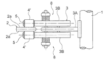
以下図1ないし図4を参照して本発明の実施形態を詳細に説明する。図1及び図2は本発明の第1の実施形態の構成を示したもので、これらの図において、1は軸線O1−O1を中心として回転し得るように、図示しない軸受け装置により回転自在に支持されて、図示しない蓄勢機構により一方向及び他方向に回転するように操作される回転操作軸である。2,2は、回転操作軸1の中心軸線O1−O1を中心とする円弧に沿って、回転操作軸1の中心軸線O1−O1と直交する平面上に並べて配置された複数(図示の例では2個)の板状の固定コンタクトで、各固定コンタクト2は、回転操作軸1の軸線方向に沿う方向に向いた電極面2a,2aを表裏に有している。
Hereinafter, embodiments of the present invention will be described in detail with reference to FIGS. 1 and 2 show the configuration of the first embodiment of the present invention. In these drawings, 1 can be rotated by a bearing device (not shown) so that it can rotate around an axis O1-O1. It is a rotation operation shaft that is supported and operated to rotate in one direction and the other direction by a storage mechanism (not shown).
3は回転操作軸1に後端部が固定されて、回転操作軸1の回転に伴って、回転操作軸1の軸線と直交する平面上で回動する導電性のアーム、4は回転操作軸1の軸線O1−O1に対して直角な方向に中心軸線を向けてアーム3の先端に設けられた導電性のローラ支持軸5に回転自在に支持されたローラコンタクトである。ローラコンタクト4は、アーム3の回動に伴って回転操作軸1の中心軸線を中心とした円弧に沿って回動しつつ、各固定コンタクト2の電極面2a上を転動する。
図示の例では、アーム3が、回転操作軸1の軸線と直交する方向に延びるように設けられて、回転操作軸1に後端部が固定された第1のアーム3Aと、該第1のアーム3Aを間にして回転操作軸1の軸線方向に並ぶように設けられて、回転操作軸1の軸線と平行な方向に延びる回動軸11により第1のアーム3Aの先端に回動自在に支持された一対の第2のアーム3B,3Bとからなっている。
In the illustrated example, the
ローラ支持軸5は一対設けられていて、該一対のローラ支持軸5,5が、それぞれの中心軸線O2−O2を一対の第2のアーム3B,3Bの長手方向に向けた状態で、一対の第2のアーム3B,3Bの先端にそれぞれ一体に設けられている。またローラコンタクト4も一対設けられていて、該一対のローラコンタクト4,4がそれぞれ一対のローラ支持軸5,5に回転自在に支持されている。一対のローラコンタクト4,4は、各固定コンタクト2A,2Bを間に挟む状態で各固定コンタクトの表裏両面に接触させられる。
A pair of
各第2のアーム3Bの、回動軸11よりも回転操作軸1側に位置する部分には、第1のアーム3A側に突出した突起301(図2参照)が設けられ、各第2のアーム3Bの突起301が第1のアーム3Aに接触させられている。
Projections 301 (see FIG. 2) projecting to the
回動軸11は、第1のアーム3Aの先端部と、第2のアーム3B,3Bの中間部とを貫通した状態で設けられていて、回動軸11の第2のアーム3B,3Bを突き抜けて上下に突出した部分にそれぞれ接圧バネ12,12が嵌合されている。回動軸11の両端部寄りの部分にそれぞれバネ受け板13,13が嵌合され、回動軸11に形成された貫通孔に挿入された割ピン14,14により、バネ受け板13,13の回動軸11からの抜け止めが図られるとともに、回動軸11の軸線方向への変位が規制されている。バネ受け板13,13と第2のアーム3B,3Bとの間に接圧バネ12,12が圧縮された状態で保持され、これらの接圧バネにより、ローラコンタクト4,4が固定コンタクト2側に付勢されている。本実施形態では、回動軸11と、接圧バネ12,12と、バネ受け板13,13とにより、一対のローラコンタクト4,4を互いに接近する方向に付勢して、両ローラコンタクトと各固定コンタクトの電極面2a,2aとの間に接触圧力を付与する接圧付与機構15が構成されている。
The
図1に示されているように、第1のアーム3Aには、可撓性を有する集電導体19が接続されていて、ローラコンタクト4がローラ支持軸5と第2のアーム3Bと第1のアーム3Aと、集電導体19とを通して外部の回路に接続される。本実施形態の開閉器を図6に示された切換開閉器の補助開閉器SWとして用いる場合には、固定コンタクト2,2の一方及び他方がそれぞれ固定コンタクトS1及びS2を構成する。またローラコンタクト4が可動コンタクトS0を構成し、集電導体19が真空バルブV1に接続される。
As shown in FIG. 1, a flexible
本実施形態では、各ローラコンタクト4が、導電材料からなる複数(図示の例では5個)の外径が等しいローラ400,400,…からなっている。複数のローラ400,400,…は、中心軸線をローラ支持軸5の軸線O2−O2方向に向けて並べて配置されて、互いに独立に回転し得るようにして、ローラ支持軸5に回転自在に支持されている。
In the present embodiment, each
本実施形態のように、ローラコンタクト4を、軸線方向に並べて配置されて互いに独立に回転する複数のローラ400により構成すると、複数のローラ400を、ローラコンタクト4の回動中心O1−O1からの距離に応じて異なる回転速度で回転させて、固定コンタクトの電極面上を転動させることができるため、ローラコンタクト4と固定コンタクト2との間でスリップが生じるのを防いで、安定な切換動作を行なわせることができる。
When the
また上記のように構成すると、ローラコンタクト4を截頭円錐形に形成する場合のように、ローラコンタクトを製作する際に、加工精度の厳密な管理を要する面倒な機械加工を必要としない。またローラコンタクトの回動中心O1−O1と固定コンタクト2との間の距離が異なる場合でも、ローラコンタクト4を構成する各ローラ400の径は異ならせる必要がないため、回転操作軸1と固定コンタクト2との間の距離が異なる種々の型式の開閉器に対して共通のローラ400を用いて、部品の共用化を図り、製造コストの低減を図ることができる。
Moreover, when comprised as mentioned above, when manufacturing the roller contact like the case where the
また上記のようにローラコンタクト4を複数のローラ400により構成すると、ローラコンタクト4を固定コンタクト2に多点で接触させることができるため、開閉器の電流通電容量を増大させることができ、通電容量が同一である場合にはローラコンタクトの小形化を図ることができる。
Further, when the
図3は、本発明の第2の実施形態の要部を示したものである。この実施形態では、ローラコンタクト4を構成する各ローラ400とローラ支持軸5との間に波形の導電性バネ20が挿入されて、各ローラ400がバネ20を介して各ローラ支持軸5に支持されている。導電性バネ20は、ローラ400とローラ支持軸5との双方に接触して両者間を電気的に接続する。このように構成すると、ローラコンタクト4を構成する各ローラ400が回転操作軸1の軸線方向に変位することが許容されるため、ローラの追従性を良好にすることができる。
FIG. 3 shows a main part of the second embodiment of the present invention. In this embodiment, a corrugated
図4(A)及び(B)は、本発明の第3の実施形態の要部を示したもので、本実施形態においては、ローラ支持軸が複数のローラ400に対して共通に設けられるのではなく、複数のローラ400,400,…のそれぞれに対して個別にローラ支持軸500が設けられ、各ローラ400に対して設けられたローラ支持軸500が、回転操作軸1の軸線方向(図4において上下方向)に変位し得るように、第2のアーム3Bに導電性の弾性支持部材21を介して支持されている。
FIGS. 4A and 4B show the main part of the third embodiment of the present invention. In this embodiment, a roller support shaft is provided in common for a plurality of
図示の例では、弾性支持部材21が、第2のアーム3Bに溶接等により電気的及び機械的に接続された基部21aと、基部21aに後端部が一体化された状態で設けられて固定コンタクト2側に傾斜して延びる腕部21bと、腕部21bの先端に一体に形成された二股状のローラ支持部21cとを有する形状に形成されている。ローラ400は、弾性支持部材21のローラ支持部21cの二股部分の間に挿入されて、該二股部分を貫通したローラ支持軸500によりローラ支持部21cに回転自在に支持されている。各ローラ400は、弾性支持部材21の腕部21bの弾性により、回転操作軸1の軸線方向への変位が許容される。この場合、ローラ400をローラ支持軸500に固定して、該ローラ支持軸500をローラ支持部21cに回転自在に支持するようにしてもよく、ローラ支持軸500をローラ支持部21cに固定して、ローラ400をローラ支持軸500に回転自在に支持するようにしてもよい。
In the illustrated example, the
このように構成した場合も、各ローラ400が回転操作軸の軸線方向に個別に変位することが許容されるため、ローラコンタクトの追従性を良好にすることができる。
Even in such a configuration, each
上記の実施形態では、固定コンタクト2が2個だけ設けられているが、3以上の固定コンタクトが設けられる開閉器にも本発明を適用できるのはもちろんである。
In the above embodiment, only two fixed
また上記の実施形態では、ローラコンタクト4を5個のローラ400により構成したが、ローラコンタクト4は複数個のローラ400により構成されればよく、ローラ400の数は任意である。電流容量に応じてローラ400の数を増減することができる。
In the above embodiment, the
上記の説明では、本発明に係わる開閉器を、負荷時タップ切換装置の補助開閉器として用いるとしたが、他の用途にも用いることができるのはもちろんである。 In the above description, the switch according to the present invention is used as an auxiliary switch of the on-load tap switching device, but it can of course be used for other purposes.
1 回転操作軸
2 固定コンタクト
3 アーム
3A 第1のアーム
3B 第2のアーム
4 ローラコンタクト
400 ローラ
5,500 ローラ支持軸
11 回動軸
12 接圧バネ
13 ナット
21 弾性支持部材
DESCRIPTION OF
Claims (5)
前記ローラコンタクトは、中心軸線を前記回転操作軸の軸線に対して直角な方向に向けた状態で並べて配置されて、前記アームにローラ支持軸を介して回転自在に支持された複数の導電性のローラからなり、
前記複数のローラは、互いに独立に回転し得るように設けられ、
各固定コンタクトは前記回転操作軸の軸線方向に向いた電極面を表裏両面に有し、
前記アームは、前記回転操作軸に後端部が取り付けられた第1のアームと、該第1のアームを間にして前記回転操作軸の軸線方向に並ぶように設けられて、前記回転操作軸の軸線と平行な方向に延びる回動軸により前記第1のアームの先端に回動自在に支持された一対の第2のアームとからなり、
前記ローラコンタクトは一対設けられていて、該一対のローラコンタクトがそれぞれ前記一対の第2のアームの先端にローラ支持軸を介して支持されて、前記一対のローラコンタクトが前記各固定コンタクトを間に挟む状態で各固定コンタクトの表裏両面に接触するように構成され、
前記一対のローラコンタクトを互いに接近する方向に付勢して、前記一対のローラコンタクトと各固定コンタクトの電極面との間に接触圧力を付与する接圧付与機構が設けられていること、
を特徴とする開閉器。 A rotation operation shaft that is rotatably supported and operated to rotate in one direction and the other direction, and a center axis of the rotation operation shaft having an electrode surface oriented in a direction along the axial direction of the rotation operation shaft A plurality of plate-like fixed contacts arranged side by side on a plane perpendicular to the central axis of the rotation operation axis along an arc centered on the rotation operation shaft, and a rear end portion attached to the rotation operation shaft, the rotation operation A conductive arm that rotates as the shaft rotates, and a rotating arm that is rotatably supported at the tip of the arm with the central axis oriented in a direction perpendicular to the axis of the rotation operation shaft. A roller contact that rolls on the electrode surface of each fixed contact with movement, and a switch that switches the fixed contact on which the roller contact rolls with the rotation of the rotation operation shaft.
The roller contacts are arranged side by side with their central axes oriented in a direction perpendicular to the axis of the rotational operation shaft, and a plurality of conductive contacts rotatably supported by the arms via roller support shafts. Made of rollers,
The plurality of rollers are provided to be able to rotate independently of each other ,
Each fixed contact has an electrode surface facing both the front and back surfaces in the axial direction of the rotation operation shaft,
The arm is provided with a first arm having a rear end attached to the rotation operation shaft, and arranged in the axial direction of the rotation operation shaft with the first arm interposed therebetween, and the rotation operation shaft A pair of second arms rotatably supported at the tip of the first arm by a rotation shaft extending in a direction parallel to the axis of
A pair of the roller contacts are provided, and the pair of roller contacts are respectively supported at the tips of the pair of second arms via a roller support shaft, and the pair of roller contacts interpose the fixed contacts. It is configured to contact both the front and back surfaces of each fixed contact in a sandwiched state,
A contact pressure applying mechanism is provided that applies a contact pressure between the pair of roller contacts and the electrode surface of each fixed contact by urging the pair of roller contacts in a direction approaching each other;
A switch characterized by.
前記ローラコンタクトは、中心軸線を前記回転操作軸の軸線に対して直角な方向に向けた状態で並べて配置されて、前記アームにローラ支持軸を介して回転自在に支持された複数の導電性のローラからなり、
前記複数のローラは、互いに独立に回転し得るように設けられ、
前記ローラコンタクトを構成する各ローラと各ローラを支持するローラ支持軸との間に導電性のバネが挿入されて、各ローラが該バネを介して前記ローラ支持軸に接触させられ、
前記ローラコンタクトを構成する各ローラが前記回転操作軸の軸線方向に変位し得るように構成されていること、
を特徴とする開閉器。 A rotation operation shaft that is rotatably supported and operated to rotate in one direction and the other direction, and a center axis of the rotation operation shaft having an electrode surface oriented in a direction along the axial direction of the rotation operation shaft A plurality of plate-like fixed contacts arranged side by side on a plane perpendicular to the central axis of the rotation operation axis along an arc centered on the rotation operation shaft, and a rear end portion attached to the rotation operation shaft, the rotation operation A conductive arm that rotates as the shaft rotates, and a rotating arm that is rotatably supported at the tip of the arm with the central axis oriented in a direction perpendicular to the axis of the rotation operation shaft. A roller contact that rolls on the electrode surface of each fixed contact with movement, and a switch that switches the fixed contact on which the roller contact rolls with the rotation of the rotation operation shaft.
The roller contacts are arranged side by side with their central axes oriented in a direction perpendicular to the axis of the rotational operation shaft, and a plurality of conductive contacts rotatably supported by the arms via roller support shafts. Made of rollers,
The plurality of rollers are provided to be able to rotate independently of each other,
A conductive spring is inserted between each roller constituting the roller contact and a roller support shaft supporting each roller, and each roller is brought into contact with the roller support shaft via the spring,
Each roller constituting the roller contact is configured to be able to be displaced in the axial direction of the rotation operation shaft ;
A switch characterized by.
前記ローラコンタクトは、中心軸線を前記回転操作軸の軸線に対して直角な方向に向けた状態で並べて配置されて、前記アームにローラ支持軸を介して回転自在に支持された複数の導電性のローラからなり、
前記複数のローラは、互いに独立に回転し得るように設けられ、
前記ローラ支持軸は、前記複数のローラのそれぞれに対して個別に設けられていて、各ローラに対して設けられたローラ支持軸が、前記回転操作軸の軸線方向に変位し得るように、前記第2のアームに導電性の弾性支持部材を介して支持されていること、
を特徴とする開閉器。 A rotation operation shaft that is rotatably supported and operated to rotate in one direction and the other direction, and a center axis of the rotation operation shaft having an electrode surface oriented in a direction along the axial direction of the rotation operation shaft A plurality of plate-like fixed contacts arranged side by side on a plane perpendicular to the central axis of the rotation operation axis along an arc centered on the rotation operation shaft, and a rear end portion attached to the rotation operation shaft, the rotation operation A conductive arm that rotates as the shaft rotates, and a rotating arm that is rotatably supported at the tip of the arm with the central axis oriented in a direction perpendicular to the axis of the rotation operation shaft. A roller contact that rolls on the electrode surface of each fixed contact with movement, and a switch that switches the fixed contact on which the roller contact rolls with the rotation of the rotation operation shaft.
The roller contacts are arranged side by side with their central axes oriented in a direction perpendicular to the axis of the rotational operation shaft, and a plurality of conductive contacts rotatably supported by the arms via roller support shafts. Made of rollers,
The plurality of rollers are provided to be able to rotate independently of each other,
The roller support shaft is individually provided for each of the plurality of rollers, and the roller support shaft provided for each roller can be displaced in the axial direction of the rotation operation shaft. Being supported by the second arm via a conductive elastic support member ;
A switch characterized by.
前記ローラコンタクトを構成する各ローラが前記回転操作軸の軸線方向に変位し得るように構成されていること、
を特徴とする請求項1に記載の開閉器。 A conductive spring is inserted between each roller constituting the roller contact and a roller support shaft supporting each roller, and each roller is brought into contact with the roller support shaft via the spring,
Each roller constituting the roller contact is configured to be able to be displaced in the axial direction of the rotation operation shaft;
The switch according to claim 1 .
を特徴とする請求項1に記載の開閉器。
The roller support shaft is individually provided for each of the plurality of rollers, and the roller support shaft provided for each roller can be displaced in the axial direction of the rotation operation shaft. Being supported by the second arm via a conductive elastic support member;
The switch according to claim 1 .
Priority Applications (1)
| Application Number | Priority Date | Filing Date | Title |
|---|---|---|---|
| JP2011003738A JP5649985B2 (en) | 2011-01-12 | 2011-01-12 | Switch |
Applications Claiming Priority (1)
| Application Number | Priority Date | Filing Date | Title |
|---|---|---|---|
| JP2011003738A JP5649985B2 (en) | 2011-01-12 | 2011-01-12 | Switch |
Publications (2)
| Publication Number | Publication Date |
|---|---|
| JP2012146499A JP2012146499A (en) | 2012-08-02 |
| JP5649985B2 true JP5649985B2 (en) | 2015-01-07 |
Family
ID=46789894
Family Applications (1)
| Application Number | Title | Priority Date | Filing Date |
|---|---|---|---|
| JP2011003738A Active JP5649985B2 (en) | 2011-01-12 | 2011-01-12 | Switch |
Country Status (1)
| Country | Link |
|---|---|
| JP (1) | JP5649985B2 (en) |
Families Citing this family (1)
| Publication number | Priority date | Publication date | Assignee | Title |
|---|---|---|---|---|
| JP7063591B2 (en) * | 2017-12-08 | 2022-05-09 | 株式会社ダイヘン | Switching switch |
Family Cites Families (2)
| Publication number | Priority date | Publication date | Assignee | Title |
|---|---|---|---|---|
| JPH06349371A (en) * | 1993-06-08 | 1994-12-22 | Mitsubishi Electric Corp | Switch |
| JP2010186719A (en) * | 2009-02-13 | 2010-08-26 | Daihen Corp | Changeover switch |
-
2011
- 2011-01-12 JP JP2011003738A patent/JP5649985B2/en active Active
Also Published As
| Publication number | Publication date |
|---|---|
| JP2012146499A (en) | 2012-08-02 |
Similar Documents
| Publication | Publication Date | Title |
|---|---|---|
| JP6316284B2 (en) | Load tap changer | |
| CN103282850A (en) | Rotary/push operating device for a man-machine interface | |
| JP5649985B2 (en) | Switch | |
| JP2015525435A (en) | Device consisting of multiple vacuum valves in a switching switch | |
| JP2010080590A (en) | Change-over switch for on-load tap changer | |
| JP5784708B2 (en) | Load switching switch for on-load tap changer | |
| JP4231866B2 (en) | Tap selector | |
| US2452916A (en) | Rotary tap switch | |
| BR112018003926B1 (en) | LOAD SWITCH TO A LOAD BYPASS SWITCH AND CONTINUOUS MAIN SWITCH AND DISCONNECT SWITCH TO THE SAME | |
| CN105655158A (en) | Rotor and electromechanical switching device having a rotor | |
| JP2010186719A (en) | Changeover switch | |
| JP2013526772A5 (en) | ||
| JP4369028B2 (en) | Switching switch for tap switching device under load | |
| JP2013247170A (en) | Changeover switch and on-load tap changer using the same | |
| JP4087168B2 (en) | Vacuum valve type load tap changer | |
| JP2023025140A (en) | Torque adjuster and tap changer | |
| JPS637647B2 (en) | ||
| JP6415334B2 (en) | Power switch | |
| JP4464314B2 (en) | Electric hand | |
| JP4240725B2 (en) | Load tap changer | |
| JP2001015357A (en) | On-load tap changer | |
| JP2012210070A (en) | Rotor of motor and method for manufacturing the same | |
| JP3913727B2 (en) | Contact for no-voltage tap changer | |
| WO2023139643A1 (en) | Changeover switch for on-load tap changer, and on-load tap changer | |
| JP4939566B2 (en) | Tap selector |
Legal Events
| Date | Code | Title | Description |
|---|---|---|---|
| A621 | Written request for application examination |
Free format text: JAPANESE INTERMEDIATE CODE: A621 Effective date: 20131212 |
|
| A131 | Notification of reasons for refusal |
Free format text: JAPANESE INTERMEDIATE CODE: A131 Effective date: 20140729 |
|
| A977 | Report on retrieval |
Free format text: JAPANESE INTERMEDIATE CODE: A971007 Effective date: 20140730 |
|
| A521 | Request for written amendment filed |
Free format text: JAPANESE INTERMEDIATE CODE: A523 Effective date: 20140926 Free format text: JAPANESE INTERMEDIATE CODE: A821 Effective date: 20140926 |
|
| RD02 | Notification of acceptance of power of attorney |
Free format text: JAPANESE INTERMEDIATE CODE: A7422 Effective date: 20140926 |
|
| TRDD | Decision of grant or rejection written | ||
| A01 | Written decision to grant a patent or to grant a registration (utility model) |
Free format text: JAPANESE INTERMEDIATE CODE: A01 Effective date: 20141028 |
|
| A61 | First payment of annual fees (during grant procedure) |
Free format text: JAPANESE INTERMEDIATE CODE: A61 Effective date: 20141112 |
|
| R150 | Certificate of patent or registration of utility model |
Ref document number: 5649985 Country of ref document: JP Free format text: JAPANESE INTERMEDIATE CODE: R150 |
|
| R250 | Receipt of annual fees |
Free format text: JAPANESE INTERMEDIATE CODE: R250 |
|
| R250 | Receipt of annual fees |
Free format text: JAPANESE INTERMEDIATE CODE: R250 |
|
| R250 | Receipt of annual fees |
Free format text: JAPANESE INTERMEDIATE CODE: R250 |
|
| R250 | Receipt of annual fees |
Free format text: JAPANESE INTERMEDIATE CODE: R250 |
|
| R250 | Receipt of annual fees |
Free format text: JAPANESE INTERMEDIATE CODE: R250 |
|
| R250 | Receipt of annual fees |
Free format text: JAPANESE INTERMEDIATE CODE: R250 |
|
| R250 | Receipt of annual fees |
Free format text: JAPANESE INTERMEDIATE CODE: R250 |