JP5648353B2 - Robot hand and robot - Google Patents
Robot hand and robot Download PDFInfo
- Publication number
- JP5648353B2 JP5648353B2 JP2010165590A JP2010165590A JP5648353B2 JP 5648353 B2 JP5648353 B2 JP 5648353B2 JP 2010165590 A JP2010165590 A JP 2010165590A JP 2010165590 A JP2010165590 A JP 2010165590A JP 5648353 B2 JP5648353 B2 JP 5648353B2
- Authority
- JP
- Japan
- Prior art keywords
- finger
- shape
- robot
- joint
- gripping
- Prior art date
- Legal status (The legal status is an assumption and is not a legal conclusion. Google has not performed a legal analysis and makes no representation as to the accuracy of the status listed.)
- Active
Links
Images


Description
本発明は、ロボットハンドを駆動することによって対象物を把持する技術に関する。 The present invention relates to a technique for gripping an object by driving a robot hand.
近年のロボット技術の進歩により、工業製品の製造現場では、多くの産業用ロボットが
使用されるようになっている。例えば、工業製品の組み立てラインでは、ラインに沿って
複数台の産業用ロボットが設置され、ライン上を流れる製造中の製品に対して、ロボット
が自動で各種の部品を組み付けることで、生産効率を向上させることが広く行われている
。あるいは、このようなロボットが組み付ける部品をラインサイドまで搬送する際にも、
ロボットを用いて部品を搬送することで、工場全体としての生産効率を向上させることも
広く行われている。
Due to recent advances in robot technology, many industrial robots have been used in industrial product manufacturing sites. For example, in an assembly line for industrial products, multiple industrial robots are installed along the line, and the robot automatically assembles various parts to the product being manufactured that flows on the line. Improvement is widely done. Or when transporting parts assembled by such robots to the line side,
It is also widely performed to improve production efficiency as a whole factory by conveying parts using a robot.
このように組み立てライン等で用いられる産業用ロボットは、基本的には対象物を掴む
動作、および掴んだ対象物を放す動作の2種類の動作をしているに過ぎないが、対象物に
は、様々な形状あるいは大きさのものが存在しているため、これらの対象物を同じように
掴んだり放したりすることは容易なことではない。そこで、ロボットが対象物を把持する
部分(ロボットハンド)を、対象物の形状や大きさに合わせて複数種類用意しておき、対
象物に合わせて適したロボットハンドを使い分けることが通常である。尚、このように対
象物を掴んだり放したりするだけの単純な動作を行うロボットハンドは、「グリッパー型
ロボットハンド(あるいは、単にグリッパー)」と呼ばれることがある。
As described above, industrial robots used in assembly lines and the like basically have only two types of movements: an operation of grasping an object and an operation of releasing the grasped object. Since there are various shapes and sizes, it is not easy to grasp and release these objects in the same way. Therefore, it is usual to prepare a plurality of types (robot hands) where the robot grips the object in accordance with the shape and size of the object, and use different robot hands suitable for the object. Note that a robot hand that performs a simple operation of simply grabbing and releasing an object in this way is sometimes called a “gripper-type robot hand (or simply a gripper)”.
もっとも、複数種類のロボットハンドを使い分けるのでは、対象物の形状や大きさが変
わる度に、ロボットハンドを付け替える作業が必要となり、その間は組み立てラインの停
止を余儀なくされるので生産効率が低下してしまう。そこで、異なる形状や大きさの対象
物に対しても同じロボットハンドで対応可能とするために、人間の手を模して複数本の指
を備えたロボットハンドが開発されている(特許文献1)。このロボットハンドは、手の
ひらに相当する部材から複数本の指が立設されており、各指には、複数の関節が設けられ
ている。そして、各指の関節と関節との間の部材(リンクと呼ばれることがある)には、
対象物との接触状態を検知するセンサーが設けられている。尚、以下では、このようなロ
ボットハンドを「多関節指型ロボットハンド」と呼ぶものとする。提案されている多関節
指型ロボットハンドでは、各指に設けられた複数のセンサーで対象物との接触状態を検知
しながら、各指のリンクが対象物と均等に接触するように関節を動かすことで、異なる形
状や異なる大きさを有する対象物であっても適切に把持することが可能となる。
However, when using multiple types of robot hands, it is necessary to change the robot hand each time the shape or size of the object changes. During that time, the assembly line must be stopped, which reduces production efficiency. End up. Therefore, in order to be able to handle objects of different shapes and sizes with the same robot hand, a robot hand having a plurality of fingers imitating a human hand has been developed (Patent Document 1). ). In this robot hand, a plurality of fingers are erected from a member corresponding to the palm, and each finger is provided with a plurality of joints. The members between the joints of each finger (sometimes called links)
A sensor for detecting a contact state with the object is provided. In the following, such a robot hand is referred to as an “articulated finger type robot hand”. In the proposed multi-joint finger type robot hand, the joint is moved so that the link of each finger contacts the target evenly while detecting the contact state with the target with a plurality of sensors provided on each finger. As a result, even objects having different shapes and sizes can be appropriately gripped.
しかし、提案されている多関節指型ロボットハンドは、それぞれの指に設けられた複数
のセンサーからの情報に基づいて、各指に設けられた複数の関節の動きを制御しなければ
ならないので、ロボットハンドを含めたロボット全体の制御がたいへん複雑になってしま
うという問題がある。また、複数の関節がほぼ並行して動作するので、動作を制御するた
めの処理量が多くなってしまい、迅速に動作させることが難しい。更に、複数の関節が同
時に動作するので一度に多くの電力が必要となり、その結果、大容量の電源が必要になる
という問題がある。
However, since the proposed multi-joint finger type robot hand has to control the movement of a plurality of joints provided for each finger based on information from a plurality of sensors provided for each finger, There is a problem that the control of the entire robot including the robot hand becomes very complicated. In addition, since the plurality of joints operate in parallel, the amount of processing for controlling the operation increases, and it is difficult to operate quickly. Furthermore, since a plurality of joints operate at the same time, a large amount of power is required at one time. As a result, there is a problem that a large capacity power source is required.
この発明は、従来の技術が有する上述した課題の少なくとも一部を解決するためになさ
れたものであり、種々の対象物を適切に把持することができるという特長を損なうことな
く、多関節指型ロボットハンドを備えるロボットを単純な制御で動作させることが可能な
技術を提供することを目的とする。
The present invention has been made in order to solve at least a part of the above-described problems of the prior art, and is an articulated finger type without impairing the feature that various objects can be appropriately gripped. It is an object of the present invention to provide a technique capable of operating a robot including a robot hand with simple control.
上述した課題の少なくとも一部を解決するために、本発明のロボットの駆動装置は次の
構成を採用した。すなわち、
対向して設けられた複数本の指部を備え、少なくとも一方の指部には複数の関節が設け
られており、該複数本の指部を用いて対象物を把持する動作を行うロボットの駆動装置で
あって、
把持しようとする前記対象物に応じて前記複数の関節を動かすことにより、該複数の関
節を備えた前記指部の形状を、該対象物を把持している時の形状である把持形状に変形す
る指形状変形手段と、
前記把持形状を保持したままで、前記複数本の指部を用いて前記対象物を把持する把持
動作手段と
を備えることを要旨とする。
In order to solve at least a part of the problems described above, the robot driving apparatus of the present invention employs the following configuration. That is,
Driving a robot having a plurality of fingers provided opposite to each other, at least one finger having a plurality of joints, and performing an operation of gripping an object using the plurality of fingers A device,
By moving the plurality of joints in accordance with the object to be gripped, the shape of the finger portion having the plurality of joints is transformed into a gripping shape that is the shape when the object is gripped. Finger shape deforming means,
And a gripping operation means for gripping the object using the plurality of finger portions while maintaining the grip shape.
また、上記のロボットの駆動装置に対応する本発明のロボットの駆動方法は、
対向して設けられた複数本の指部を備え、少なくとも一方の指部には複数の関節が設け
られており、該複数本の指部を用いて対象物を把持する動作を行うロボットの駆動方法で
あって、
把持しようとする前記対象物に応じて前記複数の関節を動かすことにより、該複数の関
節を備えた前記指部の形状を、該対象物を把持している時の形状である把持形状に変形す
る第1工程と、
前記把持形状を保持したままで、前記複数本の指部を用いて前記対象物を把持する第2
工程と
を備えることを要旨とする。
The robot driving method of the present invention corresponding to the robot driving device described above is
Driving a robot having a plurality of fingers provided opposite to each other, at least one finger having a plurality of joints, and performing an operation of gripping an object using the plurality of fingers A method,
By moving the plurality of joints in accordance with the object to be gripped, the shape of the finger portion having the plurality of joints is transformed into a gripping shape that is the shape when the object is gripped. A first step of
A second gripping the object using the plurality of fingers while holding the grip shape.
The gist is to provide a process.
こうした本発明のロボットの駆動装置あるいは駆動方法においては、対向して設けられ
た複数本の指部を用いて対象物を把持するに先立って、複数の関節を備えた指部の形状を
、対象物に応じた把持形状に変形する。ここで把持形状とは、対象物を把持している時の
指部の形状である。従って、把持形状は、把持する対象物によって異なった形状となる。
そして、指部の形状を把持形状に保持したまま、対向して設けられた複数本の指部を用い
て、対象物を把持する動作を行う。
In such a robot driving apparatus or driving method according to the present invention, prior to gripping a target object using a plurality of opposing finger portions, the shape of the finger portion having a plurality of joints is measured. Deforms to a gripping shape according to the object. Here, the grip shape is the shape of the finger when gripping an object. Therefore, the grip shape is different depending on the object to be gripped.
And the operation | movement which hold | grips a target object is performed using the several finger part provided facing, holding the shape of a finger part in a holding | grip shape.
こうすれば、指部の形状が対象物に応じた把持形状に変形されているので、対象物を適
切に把持することができる。また、指部を把持形状に保持したままで対象物を把持してい
るので、いわゆるグリッパー型ロボットハンドを備えたロボットと同様に、単純な制御で
対象物を把持することができる。更に、把持する対象物が変更された場合でも、指部の形
状を新たな対象物に応じた把持形状に変形すればよいので、柔軟に且つ迅速に対応するこ
とが可能となる。もちろん、把持しようとする対象物に応じて、適切な把持形状を予め設
定しておかなければならないが、ロボットは把持する対象物の形状が分かっていることが
多いので、ほとんどの場合は、上述した方法でロボットを駆動することで適切に対象物を
把持することができる。特に、製造現場で用いられるロボットの場合には、把持する対象
物の形状は予め決まっているので、上述した方法で駆動することで、全ての対象物を適切
に把持することが可能となる。
By so doing, the shape of the finger part is deformed into a gripping shape corresponding to the object, so that the object can be appropriately gripped. In addition, since the object is held while the finger part is held in the holding shape, the object can be held by simple control as in the case of a robot having a so-called gripper type robot hand. Furthermore, even when the object to be grasped is changed, the shape of the finger portion only needs to be changed to a grasping shape corresponding to the new object, so that it is possible to respond flexibly and quickly. Of course, an appropriate gripping shape must be set in advance according to the object to be gripped, but since the robot often knows the shape of the object to be gripped, The object can be appropriately gripped by driving the robot in the manner described above. In particular, in the case of a robot used at a manufacturing site, since the shape of the object to be grasped is determined in advance, it is possible to appropriately grasp all the objects by driving by the method described above.
また、上述した本発明のロボットの駆動装置あるいは駆動方法においては、次のように
してもよい。先ず、対象物を把持するに先立って指部を把持形状に変形するに際しては、
複数の関節の中から対象物に応じて定められた一の関節よりも先端側の指部を、把持形状
に変形する。そして、対象物に応じて定められた一の関節を動かすことによって、複数本
の指部で対象物を把持するようにしてもよい。
Further, in the robot driving apparatus or driving method of the present invention described above, the following may be performed. First, when deforming the finger part into a gripping shape prior to gripping the object,
The finger part on the tip side of one joint determined according to the object from the plurality of joints is deformed into a gripping shape. And you may make it hold | grip a target object with a several finger part by moving one joint defined according to the target object.
把持しようとする対象物が小さい場合には、指部の先端側の一部を用いて把持した方が
適切に把持できる場合も存在する。そこで、このような場合には、対象物に応じて定めら
れた一の関節よりも先端側の指部を把持形状に変形した後、その一の関節を動かして対象
物を把持することで、小さな対象物でも適切に把持することが可能となる。
When the object to be grasped is small, there is a case where it is possible to appropriately grasp by grasping using a part on the tip side of the finger portion. Therefore, in such a case, after deforming the finger part on the distal end side relative to one joint determined according to the object into a gripping shape, by moving the one joint to grasp the object, Even a small object can be gripped appropriately.
また、ロボットに設けられた複数本の指部が基部材から立設されており、それら複数本
の指部のうちで、少なくとも複数の関節を備える指部については関節によって基部材に取
り付けられたロボットを駆動する場合には、次のようにして駆動してもよい。先ず、対象
物を把持するに先立って、複数の関節が設けられた指部の全体を把持形状に変形する。そ
の後、把持形状に変形した指部が基部材に取り付けられた関節を動かすことによって、対
象物を把持することとしてもよい。
Also, a plurality of fingers provided on the robot are erected from the base member, and among the plurality of fingers, a finger having at least a plurality of joints is attached to the base member by the joint. When the robot is driven, it may be driven as follows. First, prior to gripping an object, the entire finger portion provided with a plurality of joints is deformed into a gripping shape. Thereafter, the object may be grasped by moving the joint attached to the base member by the finger portion deformed to the grasping shape.
対象物を把持すると指部に対象物からの反力がかかるから、対象物を把持する際に動か
す関節は、単に把持形状を保持する関節よりも、大きなトルクを発生させる必要があり、
そのため関節のサイズも大きくなり勝ちである。そして、サイズの大きな関節は、指部の
途中に設けるよりも、指部が基部材に取り付けられている部分に設ける方が容易である。
そこで、複数の関節が設けられた指部の全体で把持形状を形成し、指部が基部材に取り付
けられた関節を動かして対象物を把持してやれば、大きなトルクを発生させて対象物をし
っかりと把持することが可能となる。
Since the reaction force from the target is applied to the finger when gripping the target, the joint that moves when gripping the target needs to generate a larger torque than the joint that simply holds the grip shape,
As a result, the size of the joint also increases and it is easy to win. And it is easier to provide a joint with a large size in the part where the finger part is attached to the base member, rather than providing it in the middle of the finger part.
Therefore, if a grip shape is formed by the entire finger part provided with a plurality of joints, and the finger part moves the joint attached to the base member to grip the object, a large torque is generated to firmly hold the object. And can be gripped.
また、複数の関節が設けられた指部を複数本備えるロボットを駆動する場合には、次の
ような方法で駆動することとしてもよい。先ず、対象物を把持するに先立って、複数の関
節が設けられた複数本の指部を、指部毎に定められた把持形状に変形する。ここで、複数
の関節が設けられた複数本の指部は、互いに対向して設けられていても良いし、他の指部
に対向するように並べて設けられていても良い。その後、それぞれの指部を把持形状に保
ったまま、対象物を把持することとしてもよい。
Moreover, when driving a robot provided with a plurality of finger portions provided with a plurality of joints, it may be driven by the following method. First, prior to gripping an object, a plurality of finger portions provided with a plurality of joints are deformed into a gripping shape determined for each finger portion. Here, the plurality of finger portions provided with the plurality of joints may be provided so as to face each other, or may be provided side by side so as to face the other finger portions. Then, it is good also as holding a target object, keeping each finger part in a holding shape.
こうすれば、指部毎に異なる把持形状に変形して対象物を把持することができるので、
対象物の形状が複雑になっても適切に把持することが可能となる。
In this way, it can be deformed into different grip shapes for each finger part and grip the object,
Even if the shape of the object becomes complicated, it is possible to hold it appropriately.
また、上述した本発明のロボットの駆動装置あるいは駆動方法は、ロボットとしての態
様で把握することも可能である。このような態様で把握された本発明のロボットは、
対向して設けられた複数本の指部を備え、少なくとも一方の指部には複数の関節が設け
られており、該複数本の指部を用いて対象物を把持するロボットであって、
把持しようとする前記対象物に応じて前記複数の関節を動かすことにより、該複数の関
節を備えた前記指部の形状を、該対象物を把持している時の形状である把持形状に変形さ
せる指部形状変形手段と、
前記把持形状を保持したまま、前記対向して設けられた前記複数本の指部を接近させる
ことにより、該複数本の指部に前記対象物を把持させる把持動作手段と
を備えることを要旨とする。
The above-described robot drive device or drive method of the present invention can also be grasped in the form of a robot. The robot of the present invention grasped in this manner is
A robot having a plurality of fingers provided opposite to each other, at least one finger having a plurality of joints, and a robot that grips an object using the plurality of fingers.
By moving the plurality of joints in accordance with the object to be gripped, the shape of the finger portion having the plurality of joints is transformed into a gripping shape that is the shape when the object is gripped. Finger shape deforming means for causing;
A gripping operation means for gripping the object by the plurality of finger portions by bringing the plurality of finger portions provided facing each other while holding the grip shape. To do.
このような構成を有する本発明のロボットによれば、複数本の指部を用いて対象物を把
持するに先立って、複数の関節を備えた指部の形状を、対象物に応じた把持形状に変形す
る。その後、指部の形状を把持形状に保持したまま、対向して設けられた複数本の指部を
接近させることで、複数本の指部を用いて、対象物を把持することができる。
According to the robot of the present invention having such a configuration, prior to gripping an object using a plurality of fingers, the shape of a finger having a plurality of joints is changed to a grip shape corresponding to the object. Transforms into Thereafter, the object can be gripped by using the plurality of fingers by bringing the plurality of fingers provided facing each other while holding the shape of the fingers in the grip shape.
このようなロボットでは、指部を把持形状に変形するための制御と、把持形状に保持し
たまま、指部を接近させて対象物を把持するための制御を行うだけで、対象物を単純な制
御で把持することができる。また、把持する対象物が変更された場合でも、指部の形状を
対象物に応じた把持形状に変形させるだけ、対象物の変更にも柔軟に且つ迅速に対応する
ことが可能となる。
In such a robot, simply performing control for deforming the finger part into a gripping shape and control for gripping the target object while holding the gripping shape, the object can be simply Can be gripped by control. Further, even when the object to be gripped is changed, it is possible to flexibly and quickly cope with the change of the object only by changing the shape of the finger part to a gripping shape corresponding to the object.
以下では、上述した本願発明の内容を明確にするために、次のような順序に従って実施
例を説明する。
A.装置構成:
B.本実施例の対象物の把持動作:
C.本実施例の把持動作の制御処理:
D.変形例:
D−1.第1変形例:
D−2.第2変形例:
D−3.第3変形例:
D−4.第4変形例:
Hereinafter, in order to clarify the contents of the present invention described above, examples will be described in the following order.
A. Device configuration:
B. Grasping operation of the object of the present embodiment:
C. Control processing of the gripping operation of the present embodiment:
D. Variations:
D-1. First modification:
D-2. Second modification:
D-3. Third modification:
D-4. Fourth modification:
A.装置構成 :
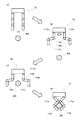
図1は、本実施例のロボットに搭載されたロボットハンド10の構成を示した説明図で
ある。図示されるように本実施例のロボットハンド10は、略矩形形状の板状部材である
掌部100や、掌部100から互いに対向するようにして立設された2本の指部110な
どから構成されている。それぞれの指部110は、短い棒状の部材(本明細書では、リン
クと呼ぶ)が、関節で他のリンクと接続されることによって、複数個のリンクが連結され
て構成されている。図1に示した例では、3つのリンクが連結されて1つの指部110が
構成されている。以下では、これらリンクを、掌部100に近い方から、第1リンク11
2、第2リンク114、第3リンク116と呼ぶものとする。また、掌部100と第1リ
ンク112とは第1関節112aによって連結されており、第1リンク112と第2リン
ク114とは第2関節114aによって連結され、第2リンク114と第3リンク116
とは第3関節116aによって連結されている。
A. Device configuration :
FIG. 1 is an explanatory diagram showing a configuration of a
2 and the
Are connected by a third joint 116a.
尚、図1に例示したロボットハンド10は、互いに向かい合う指部110は全く同じ構
造を有している。このため、図示が煩雑となることを避けるために、一方の指部110に
ついてのみ、各リンクおよび関節に符番して表示している。しかし、互いに向かい合う指
部110は、必ずしも同じ構造を有する場合に限られるわけではない。たとえば、互いに
向かい合った設けられた指部110の間で、リンクや関節の数が異なっていてもよいし、
リンクの大きさが異なっていても構わない。また、掌部100から立設する指部110は
、必ずしも同数ずつの指部110が向かい合わせに設けられている必要はなく、たとえば
2本の指部110に対向させて、1本の指部110が設けられていても構わない。
In the
The link size may be different. Further, the
それぞれの関節112a,114a,116aの中には、図示しないアクチュエーター
が内蔵されており、それぞれの関節112a,114a,116aを個別に動かすことが
可能となっている。たとえば、第1関節112aは掌部100と第1リンク112とを連
結しているから、第1関節112aに内蔵されたアクチュエーターを駆動することで、掌
部100に対して第1リンク112が立設する角度を変更することができる。また、第2
関節114aは第1リンク112と第2リンク114とを連結しているから、第2関節1
14aに内蔵のアクチュエーターを駆動することで、第1リンク112に対する第2リン
ク114の角度を変更することができる。同様に、第3関節116aに内蔵のアクチュエ
ーターを駆動すれば、第2リンク114に対する第3リンク116の角度を変更すること
が可能である。
Each joint 112a, 114a, 116a incorporates an actuator (not shown) so that each joint 112a, 114a, 116a can be moved individually. For example, since the first joint 112a connects the
Since the joint 114a connects the
The angle of the
また、各関節112a,114a,116aに内蔵されたアクチュエーターの動作は、
後述する制御部12によって制御されている。更に、指部110を構成する複数のリンク
の一部には、把持する対象物と接する側(他方の指部110と対向する側)の表面に圧力
センサー110sが設けられている。図1に示した例では、第2リンク114の表面に圧
力センサー110sが設けられている。尚、圧力センサー110sを設けるリンクは、必
ずしも第2リンク114である必要はなく、他のリンクに設けても構わない。圧力センサ
ー110sの出力は制御部12に入力されている。
In addition, the operation of the actuator built in each joint 112a, 114a, 116a is
It is controlled by the
図2には、本実施例のロボットハンド10を搭載したロボット1の大まかな構成が示さ
れている。図示されているように、ロボットの本体部16には、左右に1本ずつのロボッ
トアーム14が設けられており、そのロボットアーム14の先端に本実施例のロボットハ
ンド10が装着されている。また、本体部16の内部には、ロボットハンド10や、ロボ
ットアーム14の駆動動作を制御したり、あるいはロボット1全体の動作を制御したりす
る制御部12が搭載されている。この制御部12が、本発明の駆動装置に対応する。制御
部12は、CPUを中心としてROMやRAMがバスによって相互にデータをやり取り可
能に接続されて構成されている。尚、図2では、ロボット1の本体部16に制御部12が
内蔵されているものとしているが、制御部12は必ずしも本体部16に内蔵する必要はな
く、ロボット1の外部に別個に設置するようにしてもよい。
FIG. 2 shows a rough configuration of the
一般に、図1に示すような1本の指部に複数の関節が設けられたロボットハンド(多関
節指型ロボットハンド)では、複数の関節を動かして指部の形状を変更することができる
ので、把持しようとする対象物の大きさや形状が変更されても、それぞれの関節を適切に
動作させることによって、対象物を適切に把持することが可能である。しかし、その反面
で、関節の数が多くなるほど制御の対象が多くなるので、対象物を把持するための制御が
複雑になってしまう。そこで本実施例では、指部に多数の関節が設けられていることを有
効に活用して、大きさや形状の異なる対象物を適切に把持可能としながらも、把持するた
めの制御が複雑になることを回避するために、以下のような方法で対象物を把持すること
としている。
In general, in a robot hand (multi-joint finger type robot hand) provided with a plurality of joints on one finger as shown in FIG. 1, the shape of the finger can be changed by moving the plurality of joints. Even if the size and shape of the object to be grasped are changed, it is possible to appropriately grasp the object by appropriately operating the respective joints. However, on the other hand, the control target increases as the number of joints increases, so that the control for gripping the target object becomes complicated. Therefore, in the present embodiment, it is possible to effectively take advantage of the fact that a large number of joints are provided on the finger portion, and it is possible to appropriately grasp objects having different sizes and shapes, but the control for grasping becomes complicated. In order to avoid this, the object is held by the following method.
B.本実施例の対象物の把持動作 :
図3は、本実施例のロボットハンド10を搭載したロボットの駆動方法を用いて、大き
な対象物Waを把持する様子を示した説明図である。図3(a)には、把持動作に入る前
の状態が示されている。図示した状態では、指部110の関節に内蔵されたアクチュエー
ターには電力が供給されておらず、このため、ロボットハンド10の2本の指部110は
、重力によって垂れ下がった状態となっている。
B. Grasping operation of the object in this embodiment:
FIG. 3 is an explanatory diagram showing a state in which a large object Wa is gripped using a driving method of a robot equipped with the
この状態から、ロボットハンド10の下方にある対象物Waを把持する場合には、先ず
始めに、指部110の各関節112a,114a,116aを動かすことによって、指部
110の形状を変形させる。このときの指部110を変形させる形状は、把持しようとす
る対象物Waに応じて予め定められており、特に、指部110自体の形状(第1リンク1
12、第2リンク114、および第3リンク116によって形成される形状)は、指部1
10が対象物Waを把持したときの形状(以下、把持形状と呼ぶ)に設定されている。図
3(b)には、2本の指部110が、対象物Waに応じた把持形状に変形した様子が示さ
れている。
When gripping the object Wa below the
12, the shape formed by the
10 is set to a shape when the object Wa is gripped (hereinafter referred to as a gripping shape). FIG. 3B shows a state in which the two
続いて、各関節112a,114a,116aの角度を保ったまま(従って、指部11
0の形状を把持形状に保ったまま)、ロボットアーム14を動かすことによってロボット
ハンド10を対象物Waに近付けていく。そして、図3(c)に示したように、ロボット
ハンド10を対象物Waに対して適切な位置まで近付けたら、指部110を把持形状に保
ったままで、指部110の根元の第1関節112aのみを回転させる。その結果、図3(
d)に示されるように、2本の指部110で対象物Waを把持することができる。
Subsequently, the angles of the
The
As shown in d), the object Wa can be gripped by the two
このような把持動作によれば、図3(b)に示すように、把持しようとする対象物Wa
に応じて指部110の形状を変形した後は、指部110の根元の第1関節112aのみを
動かして対象物Waを把持することができる。そして、第1関節112aを動かして対象
物Waを把持する動作は、いわゆるグリッパーと呼ばれる単純なロボットハンドが対象物
を把持する動作と同様であり、極めて単純な制御で実現することが可能となる。
According to such a gripping operation, as shown in FIG.
After deforming the shape of the
図4は、本実施例のロボットハンド10を搭載したロボットの駆動方法を用いて、小さ
な対象物Wbを把持する様子を示した説明図である。前述した図3と同様に、図4(a)
には把持動作に入る前の状態が示されており、図4(b)には、指部110の形状を把持
形状に変形させた状態が示されている。また、図4(c)には、指部110を把持形状に
保ったまま、ロボットハンド10を対象物Wbに近付けた状態が示されており、図4(d
)には、対象物Wbを把持した状態が示されている。
FIG. 4 is an explanatory view showing a state in which a small object Wb is gripped by using a driving method of a robot equipped with the
FIG. 4B shows a state before entering the gripping operation, and FIG. 4B shows a state where the shape of the
) Shows a state where the object Wb is held.
図3(d)と図4(d)とを比較すれば明らかなように、把持する対象物の大きさ(あ
るいは形状)が異なれば、対象物を把持しているときの指部110の形状(把持形状)も
異なったものとなる。たとえば、大きな対象物Waを把持するのであれば、全てのリンク
で抱え込むような形状に指部110を変形させることで、対象物Waを適切に把持するこ
とができる。これに対して(図3(d)参照)、小さな対象物Wbの場合は、第2リンク
114および第3リンク116の部分で挟むような形状に指部110を変形させることで
、対象物Wbを適切に把持することが可能となる(図4(d)参照)。
As apparent from a comparison between FIG. 3D and FIG. 4D, if the size (or shape) of the object to be grasped is different, the shape of the
そこで、小さな対象物Wbを把持する場合には、把持動作に入ると先ず始めに、指部1
10自体の形状(第1リンク112、第2リンク114、および第3リンク116によっ
て形成される形状)を、対象物Wbに対応する把持形状に変形させる(図4(b)参照)
。その後、その把持形状を保ったまま、ロボットハンド10を対象物Wbに近付けた後(
図3(c)参照)、指部110を把持形状に保ったまま指部110の根元の第1関節11
2aのみを回転させることによって、対象物Wbを把持する。
Therefore, when gripping the small object Wb, first, when the gripping operation starts, the
The shape of 10 itself (the shape formed by the
. Thereafter, the
3 (c)), the first joint 11 at the base of the
The object Wb is gripped by rotating only 2a.
このように小さな対象物Wbを把持する場合にも、先ず始めに指部110の形状を対象
物Wbに応じた把持形状に変形しておき、その後は、指部110の根元の第1関節112
aのみを動かして対象物Wbを把持することができる。このため、いわゆるグリッパーと
呼ばれる単純なロボットハンドと同様に、極めて単純な制御で対象物Wbを把持すること
ができる。
Even when gripping such a small object Wb, first, the shape of the
The object Wb can be gripped by moving only a. For this reason, the object Wb can be gripped by extremely simple control, like a simple robot hand called a so-called gripper.
また、指部110自体の形状は、把持しようとする対象物に応じた把持形状に予め変形
されている。しかも、指部110には多くの関節が設けられているので、対象物に応じて
種々の把持形状に変形することができる。その結果、グリッパーと同様な極めて簡単な制
御でありながらも、大きさや形状の異なる多種多様な対象物を、適切に把持することが可
能となる。以下では、こうした把持動作を実現するための制御内処理ついて具体的に説明
する。
Further, the shape of the
C.本実施例の把持動作の制御処理 :
図5は、本実施例の把持動作を実現するために実行される把持動作制御処理を示したフ
ローチャートである。この処理は、制御部12に内蔵されたCPUが、ROMに記憶され
ているプログラムを実行することによって行われる処理である。図示されるように把持動
作制御処理を開始すると、先ず始めに、把持しようとする対象物を特定するための情報を
取得する(ステップS100)。図3および図4を用いて前述したように、本実施例の把
持動作では、実際に対象物を把持するに先立って、把持しようとする対象物に応じた把持
形状に指部110を変形させるので、把持しようとする対象物が予め特定されている必要
がある。そこで、把持動作制御処理を開始すると、先ず始めに、今から把持しようとする
対象物を特定するための情報を取得する。
C. Control processing of gripping operation of this embodiment:
FIG. 5 is a flowchart showing a gripping motion control process executed to realize the gripping motion of the present embodiment. This process is a process performed by the CPU built in the
ここで、対象物を特定するための情報は、制御部12の操作ボタンを操作することによ
って人間が設定してもよいし、対象物に付けられたICチップやタグ、あるいは識別コー
ドなどを制御部12が読み取ることによって取得しても良い。更には、今から把持しよう
としている対象物の画像を読み込むことによって取得してもよい。すなわち、把持する可
能性のある対象物の形状を制御部12のROMに予め記憶しておき、今から把持しようと
している対象物の画像を読み込んで、予め記憶されている対象物の何れと合致するかを判
断することによって、対象物を特定するようにしてもよい。多くの場合、把持する対象物
は予め決まっており、しかも、ロボットハンド10に対して対象物が置かれる方向もほぼ
決まっているから、このような方法によっても対象物を容易に特定することができる。
Here, the information for specifying the object may be set by a human by operating the operation button of the
把持しようとしている対象物を特定するための情報を取得したら、続いて、対象物に応
じた指部110の把持形状データを読み込む(ステップS102)。把持形状データは、
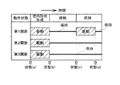
制御部12のROM内に、対象物に対応付けて予め記憶されている。図6は、制御部12
に記憶されている把持形状データを例示した説明図である。ここで、把持形状データとは
、指部110の各関節をどのような角度に設定すれば良いかを示したデータである。図6
(a)に示されているように、把持形状データは、対象物毎に設定されている。また、図
6(b)には、把持形状データに設定された角度の意味する内容が示されている。たとえ
ば、第1関節112aについて設定されている角度θ1は、掌部100の表面から第1リ
ンク112が立ち上がった角度を示している。また、第2関節114aについて設定され
ている角度θ2は、第1リンク112に対して第2リンク114が折れ曲がった角度を示
している。更に、第3関節116aについて設定されている角度θ3は、第2リンク11
4に対して第3リンク116が折れ曲がった角度を表している。
When the information for specifying the object to be grasped is acquired, the grasping shape data of the
It is stored in advance in the ROM of the
It is explanatory drawing which illustrated the grip shape data memorize | stored in. Here, the grip shape data is data indicating what angle should be set for each joint of the
As shown in (a), the grip shape data is set for each object. Further, FIG. 6B shows the meaning of the angle set in the grip shape data. For example, the angle θ <b> 1 set for the first joint 112 a indicates an angle at which the
4 represents an angle at which the
図5に示した把持動作制御処理のステップS102では、ステップS100で取得した
情報に基づいて対象物を特定し、その対象物に対して設定されている把持形状データ(各
関節112a,114a,116aの角度θ1〜θ3の値)を、制御部12のROMから
読み出す処理を行う。たとえば、把持する対象物が対象物Waであれば、第1関節112
aの角度はθ1a、第2関節114aの角度はθ2a、第3関節116aの角度はθ3a
が、把持形状データとして読み出されることになる(図6(a)参照)。
In step S102 of the gripping motion control process shown in FIG. 5, an object is identified based on the information acquired in step S100, and gripping shape data (
The angle a is θ1a, the angle of the second joint 114a is θ2a, and the angle of the third joint 116a is θ3a.
Is read as grip shape data (see FIG. 6A).
続いて、各関節112a,114a,116aに内蔵されているアクチュエーターを、
把持形状データに基づいて駆動することにより、指部110の形状を把持形状に変形させ
る(ステップS104)。尚、図6(a)に示されているように、本実施例では、対象物
に応じて1つだけの把持形状データが設定されている。従って、全ての指部110が同じ
把持形状に変形することになる。しかし、指部110毎に把持形状データを設定しておき
、それぞれの指部110を異なる把持形状に変形してもよい。こうすれば、複雑な形状を
有する対象物を把持する場合でも、より適切に把持することが可能となる。
Subsequently, the actuators built in each joint 112a, 114a, 116a are
By driving based on the grip shape data, the shape of the
こうして指部110の形状を把持形状に変形したら、その後は、いわゆるグリッパーと
呼ばれる単純なロボットハンドと同様にして、予め設定しておいた把持動作および解放動
作を実施する(ステップS106)。すなわち、先ず、ロボットハンド10を対象物の処
まで移動させ、続いて、指部110の根元の関節(第1関節112a)を動かすことによ
って、2本の指部110で対象物を把持する。このとき、第2関節114aや第3関節1
16aは動かさず、従って、指部110自体の形状は把持形状に保たれている。また、対
象物を把持する力は、指部110の第2リンク114に設けられた圧力センサー110s
の出力に基づいて制御する。そして、対象物を把持したままロボットハンド10を所定位
置まで移動させた後、第1関節112aのみを動かして(指部110を把持形状に維持し
たまま)、対象物を把持している指部110を開放する。その後、ロボットハンド10を
元の位置まで移動させる。
When the shape of the
16a does not move, and therefore the shape of the
Control based on the output of. Then, after moving the
尚、ロボットハンド10は、対象物を把持したままの状態で放置されることはあり得な
いので、対象物を把持する動作を行った後は必ず、把持した対象物を解放する動作が行わ
れる。そこで本明細書では、対象物を把持する動作と、把持した対象物を解放する動作を
まとめて「把持解放動作」と呼ぶことにする。
Since the
こうして1つの対象物についての把持解放動作を終了したら、把持すべき対象物が残っ
ているか否かを判断する(ステップS108)。この判断は、種々の方法で行うことがで
きる。たとえば、予め対象物の個数が分かっている場合には、把持解放動作を行った回数
が対象物の個数に達したか否かによって判断することができる。あるいは、把持すべき対
象物が置かれる位置の画像を取り込んで、その位置に対象物が存在するか否かに基づいて
判断したり、対象物にICチップを取り付けておき、ICチップのデータが読み込めるか
否かによっても判断することができる。
When the grip release operation for one object is completed in this way, it is determined whether or not there is an object to be gripped (step S108). This determination can be made by various methods. For example, when the number of objects is known in advance, it can be determined based on whether or not the number of times of performing the grip release operation has reached the number of objects. Alternatively, an image of a position where an object to be grasped is placed and a determination is made based on whether the object exists at that position, or an IC chip is attached to the object, and the data of the IC chip is Judgment can also be made based on whether or not data can be read.
その結果、把持すべき対象物が残っていないと判断した場合は(ステップS108:n
o)、図5の把持動作制御処理を終了する。これに対して、把持すべき対象物が残ってい
ると判断した場合は(ステップS108:yes)、その対象物が、前回に把持した対象
物と同一形状か否かを判断する(ステップS110)。この判断も種々の方法で行うこと
ができる。たとえば、把持する対象物の種類、個数、および順序がスケジュールとして予
め定められている場合には、そのスケジュールを参照することによって、次に把持する対
象物が、前回に把持した対象物と同一形状か否かを判断することができる。あるいは、対
象物にICチップやタグなどを設けておき、それらICチップやタグなどから読み取った
データと、前回に把持した対象物のデータとを比較することによって判断することができ
る。更には、対象物の画像を読み込んで、対象物の形状に基づいて判断しても良い。
As a result, when it is determined that there is no object to be gripped (step S108: n
o) The gripping motion control process in FIG. On the other hand, when it is determined that there is an object to be gripped (step S108: yes), it is determined whether or not the object has the same shape as the object gripped last time (step S110). . This determination can also be made by various methods. For example, when the type, number, and order of objects to be grasped are predetermined as a schedule, the object to be grasped next has the same shape as the object grasped last time by referring to the schedule. It can be determined whether or not. Alternatively, the determination can be made by providing an IC chip, a tag, or the like on the object, and comparing the data read from the IC chip, the tag, etc. with the data of the object gripped last time. Furthermore, the image of the object may be read and the determination may be made based on the shape of the object.
その結果、次に把持する対象物が、前回に把持した対象物と同一形状であると判断した
場合は(ステップS110:yes)、指部110の形状を把持形状に保ったまま、再び
所定の把持解放動作を実施する(ステップS106)。すなわち、ロボットハンド10を
対象物の処まで移動させ、指部110の根元の関節(第1関節112a)のみを動かして
対象物を把持する。そして、対象物を把持したままロボットハンド10を所定位置まで移
動させた後、第1関節112aのみを動かして、把持している対象物を解放したら、再び
、ロボットハンド10を元の位置に復帰させる。対象物を解放してからロボットハンド1
0を元の位置に復帰させる際にも、指部110の形状は把持形状に維持しておけばよい。
As a result, when it is determined that the object to be gripped next has the same shape as the object gripped last time (step S110: yes), the predetermined shape is again maintained while keeping the shape of the
When returning 0 to the original position, the shape of the
これに対して、次に把持する対象物が、前回に把持した対象物とは同一形状ではないと
判断した場合は(ステップS110:no)、把持動作制御処理の先頭に戻って、上述し
た一連の処理を実行する。すなわち、把持する対象物を特定するための情報を取得して(
ステップS100)、対象物に応じて新たな把持形状データを読み込んだ後(ステップS
102)、その把持形状データに従って指部110を変形させる(ステップS104)。
その結果、指部110の形状は、前回に把持した対象物に応じた把持形状から、新たな把
持形状に変化する。その後は、指部110の形状を新たな把持形状に保ったまま、予め設
定しておいた把持解放動作を実施する(ステップS106)。この把持解放動作では、上
述したように、第2関節114aや第3関節116aは動かさずに、第1関節112a(
指部110の根元の関節)のみを動かすだけなので、いわゆるグリッパー型のロボットハ
ンドと全く同様にして対象物を把持したり、解放したりすることができる。
On the other hand, when it is determined that the object to be gripped next is not the same shape as the object gripped last time (step S110: no), the process returns to the top of the gripping motion control process, and the above-described series Execute the process. That is, the information for specifying the object to be grasped is acquired (
After reading new grip shape data according to the object (step S100) (step S100)
102), the
As a result, the shape of the
Since only the joint at the base of the
こうして新たな対象物についての把持解放動作を終了したら、把持すべき対象物が残っ
ているか否かを判断し(ステップS108)、把持すべき対象物が無くなるまで、上述し
た一連の処理を繰り返す。そして、把持すべき対象物が残っていないと判断したら(ステ
ップS108:no)、図5の把持動作制御処理を終了する。
When the grip release operation for the new object is thus completed, it is determined whether or not there is an object to be gripped (step S108), and the above-described series of processing is repeated until there is no object to be gripped. If it is determined that there is no object to be gripped (step S108: no), the gripping operation control process in FIG. 5 is terminated.
図7は、上述した把持動作制御処理によって、異なる対象物に対して把持解放動作を行
う様子を示した説明図である。大きな対象物Waを把持する場合には、図7(a)に示し
た把持形状に指部110を変形させた後、対象物Waを把持したり、解放したりする動作
を繰り返す。この把持解放動作を行っている間は、指部110は同じ把持形状に保たれて
いるので、いわゆるグリッパー型のロボットハンドと全く同様に把持解放動作を行うこと
ができる。また、把持する対象物が対象物Waである限りは、指部110を変形させる必
要はないので、この点でも、グリッパー型ロボットハンドと全く同様に把持解放動作を行
うことができる。
FIG. 7 is an explanatory diagram illustrating a state in which a grip release operation is performed on different objects by the above-described grip operation control process. When gripping a large object Wa, after the
一方、把持する対象物が小さな対象物Wbに変更された場合は、図7(b)に示した把
持形状に指部110を変形させた後、対象物Wbに対して把持解放動作を行う。この場合
も、指部110を把持形状に変形した後は、把持する対象物が変更されない限り、指部1
10を変形させる必要がない。このため、小さな対象物Wbに対しても、グリッパー型ロ
ボットハンドと全く同様に把持解放動作を行うことができる。
On the other hand, when the object to be gripped is changed to a small object Wb, the
There is no need to deform 10. For this reason, the gripping and releasing operation can be performed on the small target object Wb just like the gripper type robot hand.
このように本実施例のロボットハンド10を搭載したロボットの駆動方法によれば、把
持しようとする対象物に応じて、指部110の形状を予め変形しておくことで、あたかも
グリッパー型のロボットハンドを搭載したロボットと全く同様に簡単な制御で対象物を把
持することができる。また、把持する対象物が変更された場合にも、新たな対象物に応じ
た形状に指部110を変形するだけで、適切に把持することができる。その結果、グリッ
パー型ロボットハンドを搭載したロボットのように簡単な制御でありながら、対象物が変
更されても柔軟に且つ迅速に対応して、対象物を適切に把持することが可能となる。
As described above, according to the driving method of the robot on which the
もちろん、このようにして対象物を把持するためには、対象物に応じた把持形状データ
を予め制御部12のメモリ(ROMまたはRAM)に記憶しておく必要がある。しかし、
ロボットでは、把持しようとする対象物の形状が予め分かっていることが多いので、ほと
んどの場合は、把持形状データを予め記憶しておくことができる。また、ロボットが、特
に製造現場で用いられる場合には、把持しようとする対象物は予め決まっているので、そ
れら対象物についての把持形状データを求めておくことが可能である。
Of course, in order to grip the object in this way, it is necessary to store grip shape data corresponding to the object in the memory (ROM or RAM) of the
Since the robot often knows in advance the shape of the object to be gripped, in most cases, grip shape data can be stored in advance. In addition, when the robot is used particularly at a manufacturing site, the objects to be grasped are determined in advance, and it is possible to obtain grasp shape data for these objects.
更に、上述した本実施例の駆動方法では、ロボットハンド10を搭載したロボットの制
御動作および駆動動作が時間的に分散して行われるという特徴があり、このことは制御部
12の制御負荷および電力消費の観点からも大きなメリットを生じる。以下、この点につ
いて説明する。
Furthermore, the driving method of the present embodiment described above is characterized in that the control operation and the drive operation of the robot equipped with the
図8は、本実施例のロボットハンド10を搭載したロボットの駆動方法によって、指部
110の各関節112a,114a,116aが駆動される様子を示したタイムチャート
である。図の上段には、ロボットのハンド部分(ロボットハンド10)の動作状態が示さ
れており、その下方には、指部110に設けられた各関節112a,114a,116a
の動作状態が示されている。また、図の下方の欄外には、参考として、ロボットハンド1
0の動作状態と、図3あるいは図4に示した各状態との対応関係が示されている。
FIG. 8 is a time chart showing how the
The operating state of is shown. Also, in the margin below the figure, for reference, the
The correspondence relationship between the operation state of 0 and each state shown in FIG. 3 or FIG. 4 is shown.
前述したように本実施例のロボットハンド10を搭載したロボットに駆動方法では、新
たな対象物を把持する際には、先ず始めに、指部110の形状を、対象物に応じた把持形
状に変形する。このため、図8に示したように、第1関節112a、第2関節114a、
第3関節116aが駆動される。図5を用いて前述したように、この動作は、それぞれの
関節を予め定められた角度に動かすだけなので、制御部12の制御負荷はたいへん小さな
ものに過ぎない。また、第1リンク112、第2リンク114、第3リンク116の何れ
も、対象物からの反力を受けることなく空転している状態なので、電力消費量も僅かであ
る。図8中で、把持形状を形成する際の各関節の駆動が、破線の矩形で表示されているの
は、これらの駆動が制御負荷および電力消費の何れの点についても負担の少ない駆動であ
ることを表したものである。
As described above, in the driving method of the robot equipped with the
The third joint 116a is driven. As described above with reference to FIG. 5, since this operation only moves each joint to a predetermined angle, the control load of the
指部110の形状を把持形状に変形した後は、指部110を把持形状に保ったまま、対
象物の処までロボットハンド10を移動させる。この間は、各関節では現在の角度を保持
する電力しか消費しない。また、何れの関節も動かさないので、制御部12の制御負荷は
たいへんに小さなものに過ぎない。特に、各関節を動かすためのアクチュエーターとして
、いわゆる超音波ピエゾモーターのように、動作させない限りは現在の状態を維持する特
性を有するアクチュエーターを採用すれば、指部110を把持形状に維持しておくための
制御負荷や電力消費が発生しないようにすることも可能である。
After the shape of the
そして、ロボットハンド10を対象物の処まで移動させたら、今度は、第1関節112
a(指部110の根元の関節)を駆動することによって、対象物を把持する動作を開始す
る。この段階では、第1リンク112、第2リンク114、第3リンク116が対象物か
ら反力を受けるので、第1関節112aの駆動に伴って、それなりの電力が消費される。
また、指部110の一部(本実施例では第2リンク114)に設けられた圧力センサー1
10sの出力を検出しながら、対象物が適切な力で把持されるように第1関節112aの
動きを制御しなければならないので、制御部12にもそれなりの制御負荷が発生する。一
方、第2関節114aあるいは第3関節116aについては、把持の開始後も動かす必要
はないので、現在の角度を保持する電力しか消費せず、制御部12に対する制御負荷もか
からない。
When the
The movement of gripping the object is started by driving a (the joint at the base of the finger part 110). At this stage, since the
Further, the
While detecting the output of 10 s, the movement of the first joint 112a must be controlled so that the object is gripped with an appropriate force, so that a suitable control load is generated in the
すなわち、本実施例のロボットハンド10を搭載したロボットの駆動方法では、制御部
12の制御負荷あるいは電力消費が大きくなるのは、ロボットハンド10を対象物の処に
移動させた後、実際に対象物の把持を開始してからの期間となる。しかし、対象物の把持
を開始するよりも前の段階で既に指部110を把持形状に変形しているので、実際に対象
物の把持を開始した段階では、第2関節114aや第3関節116aを動かす必要はない
。その結果、制御部12での制御負荷および電力消費の増加を抑制することが可能となる
。このようなメリットは、従来の一般的な多関節指型ロボットハンドを搭載したロボット
の駆動方法と比較することによってより顕著となる。
That is, in the driving method of the robot equipped with the
図9は、従来の一般的な多関節指型ロボットハンドを搭載したロボットと同様な駆動方
法で対象物を把持した場合の各関節112a,114a,116aの動きを示したタイム
チャートである。従来の一般的なロボットの駆動方法では、ロボットハンド10を対象物
の処まで移動させた後、全て関節を動かして対象物を把持する動作を開始する。この時、
従来の一般的な駆動方法では、各リンクが対象物から受ける反力を検出しながら、全ての
リンクが受ける反力がほぼ均等となるように、各関節の動きを制御する。このため同時に
制御する関節の数が多くなるだけでなく、ある関節の動きが他の関節の動きにも影響を与
えるため、制御部12の制御負荷がたいへんに大きくなる。その結果、把持動作を迅速に
行うことが困難となる。
FIG. 9 is a time chart showing the movement of each joint 112a, 114a, 116a when the object is gripped by the same driving method as that of a robot equipped with a conventional general articulated finger type robot hand. In the conventional general robot driving method, after the
In the conventional general driving method, the movement of each joint is controlled so that the reaction forces received by all the links are almost equal while detecting the reaction forces received by each link from the object. For this reason, not only the number of joints to be controlled simultaneously increases, but also the movement of one joint affects the movement of other joints, so the control load of the
また、全ての関節が対象物からの反力を受けた状態で駆動しなければならないので、個
々の関節の駆動に要する電力消費量も大きくなる。そして、図9に示したように、全ての
関節を同時に動かさなければならないため、ロボットハンド10全体としての電力消費量
がたいへんに大きくなってしまい、その分だけ、ロボット全体としての電力消費量も大き
くなってしまう。これに対して、図8に示した本実施例のロボットハンド10を搭載した
ロボットの駆動方法では、最も制御負荷や電力消費量が大きくなる段階(対象物を把持す
る段階)では、第1関節112aのみを動かして、第2関節114aや第3関節116a
は動かさなくて良いので、制御部12の制御負荷や、電力消費が集中して発生することが
ない。その結果、制御処理速度や電力消費量の点で制約を受けることなく迅速に把持動作
を行うことが可能になる。また、ロボットハンド10を含めたロボット全体を駆動するた
めの電源も、比較的小さな電源を採用することが可能となる。
In addition, since all the joints must be driven in a state of receiving a reaction force from the object, the power consumption required for driving each joint also increases. As shown in FIG. 9, since all the joints must be moved simultaneously, the power consumption of the
Therefore, the control load of the
尚、図8に示したように、上述した実施例では、指部110の形状を把持形状に変形し
た後に、ロボットハンド10を対象物の処まで移動させるものとして説明した。しかし、
ロボットハンド10を対象物の処まで移動させている間に、指部110の形状を把持形状
に変形しても良い。上述したように、指部110を把持形状に変形する動作は、制御負荷
も電力消費も小さいので、ロボットハンド10を移動させながら実行することも容易であ
る。従って、制御負荷や電力消費を増加させることなく、ロボットハンド10を迅速に動
作させることが可能となる。
As shown in FIG. 8, in the above-described embodiment, the
While the
D.変形例 :
上述した本実施例のロボットハンド10を搭載したロボットの駆動方法には種々の変形
例が存在している。以下では、これら変形例について簡単に説明する。
D. Modified example:
There are various modified examples of the driving method of the robot on which the
D−1.第1変形例 :
上述した実施例では、指部110を構成する全てのリンク(第1リンク112、第2リ
ンク114、第3リンク116)を用いて把持形状を形成し、指部110の根元の関節(
第1関節112a)を動かすことによって対象物を把持するものとして説明した。しかし
、対象物を把持する際に動かす関節は、必ずしも指部110の根元の関節(第1関節11
2a)に限られるものではない。すなわち、指部110の途中に設けられた関節を動かし
て対象物を把持することとして、その関節よりも先端側のリンクを用いて把持形状を形成
するようにしても良い。
D-1. First modification:
In the above-described embodiment, the grip shape is formed using all the links (the
It has been described that the object is gripped by moving the first joint 112a). However, the joint that moves when grasping the object is not necessarily the joint at the base of the finger 110 (the first joint 11).
It is not limited to 2a). In other words, a gripping shape may be formed by moving a joint provided in the middle of the
図10は、第1変形例の駆動方法を用いて小さな対象物Wbを把持する様子を示した説
明図である。図4を用いて前述したように小さな対象物Wbは、2本の指部110の第2
リンク114および第3リンク116で挟むようにして把持することができる。そこで、
第2リンク114および第3リンク116の部分で把持形状を形成することとして、先ず
始めに、指部110の形状を、図10(b)に示すような形状に変形する。次に、変形し
た指部110の形状を保ったまま、図10(c)に示したようにロボットハンド10を対
象物Wbの処まで移動させる。そして、この状態から、第2リンク114および第3リン
ク116で形成した把持形状を保ったまま、第2関節114aのみを動かすことによって
も、対象物Wbを適切に把持することができる。
FIG. 10 is an explanatory diagram showing how a small object Wb is gripped using the driving method of the first modification. As described above with reference to FIG. 4, the small object Wb is the second of the two
It can be gripped by being sandwiched between the
In forming the grip shape at the
この第1変形例の駆動方法においても、実際に対象物Wbを把持する際には第2関節1
14aのみを動かせばよく、他の関節については保持しているだけでよい。このため、い
わゆるグリッパー型のロボットハンドを搭載したロボットと同様に極めて簡単な制御で対
象物を把持することができる。また、制御部12の制御負荷や電力消費が集中して発生す
ることもない。
Even in the driving method of the first modified example, when the object Wb is actually gripped, the
It is only necessary to move 14a, and other joints need only be held. For this reason, it is possible to grip an object with extremely simple control like a robot equipped with a so-called gripper type robot hand. Further, the control load and power consumption of the
D−2.第2変形例 :
上述した実施例あるいは変形例では、関節によって指部110が掌部100に取り付け
られているものとして説明した。従って、指部110は、掌部100に対する取付位置を
中心として前後方向に振れるように回転する動きのみが可能となっていた。しかし、指部
110を掌部100の固定した位置に取り付けるのではなく、指部110の取付位置が前
後方向に移動するように構成されたロボットハンドを搭載したロボットに対しても、本発
明の駆動方法を適用することができる。
D-2. Second modification:
In the above-described embodiment or modification, it has been described that the
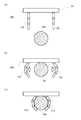
図11は、第2変形例の駆動方法を用いて対象物Waを把持する様子を示した説明図で
ある。図11に示したロボットハンド20は、2本の指部110が掌部200に取り付け
られており、それぞれの指部110の取付位置が、前後方向に移動可能となっている。こ
のようなロボットハンド20を用いて対象物Waを把持する場合にも、先ず始めに、指部
110の形状を、対象物Waに応じた把持形状に変形させる。そして、ロボットハンド2
0を対象物Waの処まで移動させた後、把持形状に保ったまま、それぞれの指部110の
取付位置を前進させる。図11(b)には、指部110の形状を把持形状に保ったまま、
取付位置を前進させる様子が示されている。こうすれば、図11(c)に示したように、
対象物Waを把持することができる。
FIG. 11 is an explanatory diagram showing a state in which the object Wa is gripped using the driving method of the second modified example. In the
After moving 0 to the place of the object Wa, the attachment position of each
The manner of advancing the mounting position is shown. In this way, as shown in FIG.
The object Wa can be gripped.
このような第2変形例の駆動方法においても、予め指部110を把持形状に変形してか
ら対象物Waを把持するので、実際に対象物Waを把持する際には指部110の取付位置
を移動させるだけでよい。このため、いわゆるグリッパー型のロボットハンドを搭載した
ロボットと同様に極めて簡単な制御で対象物を把持することができる。また、制御部12
の制御負荷や電力消費が集中して発生することもない。加えて、対象物に応じて指部11
0を適切な把持形状に変形しておくことで、把持する対象物が変更された場合でも柔軟に
且つ迅速に対応することが可能となる。
Also in the driving method of the second modified example, since the object Wa is grasped after the
The control load and power consumption are not concentrated. In addition, the finger 11 depending on the object
By transforming 0 into an appropriate gripping shape, it is possible to respond flexibly and quickly even when the object to be gripped is changed.
D−3.第3変形例 :
上述した実施例あるいは変形例では、互いに対向して設けられた指部110が、同じ形
状の指部110であるものとして説明した。しかし、対向する指部110は、必ずしも同
じ形状の指部110である必要はなく、たとえばリンクの数や大きさが異なっていても良
い。更には、一方の指部については可動部分を持たない固定式の指部であっても構わない
。このような指部を有するロボットハンドを搭載したロボットに対しても、本発明の駆動
方法を適用することができる。
D-3. Third modification:
In the above-described embodiment or modification, the
図12は、複数のリンクから構成される指部310と、可動部分を持たない固定式の指
部320とを備えたロボットを用いて対象物を把持する様子を示した説明図である。図1
2(a)には、把持動作を開始する前のロボットのハンド部分(ロボットハンド30)が
示されている。図示されているように、指部310には、第1関節312a、第2関節3
14a、第3関節316a、および第4関節318aの4つの関節が設けられている。そ
して、この指部310に対向する位置に、固定式の指部320が掌部300から立設され
ている。
FIG. 12 is an explanatory diagram showing a state in which an object is gripped using a robot provided with a
2 (a) shows a robot hand portion (robot hand 30) before the gripping operation is started. As shown, the
Four joints 14a, a third joint 316a, and a fourth joint 318a are provided. A fixed
このようなロボットハンド30を搭載したロボットを用いて対象物を把持する場合にも
、先ず始めに、指部310の形状を、対象物に応じた把持形状に変形する。たとえば、大
きな対象物Waを把持するのであれば、図12(b)に例示したような把持形状に変形す
る。一方、小さな対象物Wbを把持するのであれば、図12(d)に例示したような把持
形状に変形する。そして、ロボットハンド30を対象物の処に移動させた後、指部310
の根元の関節(第1関節312a)のみを動かすことによって、指部310と指部320
との間で対象物を把持する。図12(c)には、大きな対象物Waを把持した様子が示さ
れており、図12(e)には、小さな対象物Wbを把持した様子が示されている。
Even when a target is gripped using a robot equipped with such a
The
Grab the object in between. FIG. 12 (c) shows a state where a large object Wa is gripped, and FIG. 12 (e) shows a state where a small object Wb is gripped.
このように、対向して設けられた指部同士が、異なる形状あるいは異なる構造を有する
場合でも、指部の形状を対象物に応じた把持形状に変形しておくことで、種々の対象物を
適切に把持することが可能となる。また、実際に対象物を把持する動作は、いわゆるグリ
ッパー型のロボットハンドと同様であるため、簡単な制御で実現することができる。
As described above, even when the finger parts provided opposite to each other have different shapes or different structures, various shapes of objects can be obtained by changing the shape of the finger parts into gripping shapes corresponding to the objects. It becomes possible to grip appropriately. In addition, since the operation of actually gripping the object is the same as that of a so-called gripper type robot hand, it can be realized by simple control.
D−4.第4変形例 :
上述した実施例あるいは変形例においては、1本ずつの指部110が対向して設けられ
ているものとして説明した。しかし、本発明の駆動方法は制御負荷が軽く、電力消費量も
少ないという特徴を有していることから、複数本ずつの指部が対向して設けられたハンド
部分(ロボットハンド)を搭載したロボットの駆動方法として特に優れたものということ
ができる。
D-4. Fourth modification:
In the above-described embodiment or modification, it has been described that one
図13は、複数本ずつの指部110が対向して設けられた第4変形例のロボットのハン
ド部分(ロボットハンド40)を例示した説明図である。図示した第4変形例のロボット
のハンド部分(ロボットハンド40)には、4本の指部110が同じ方向に向けて横一列
に設けられており、これら4本の指部110に対向するようにして、同じく4本の指部1
10が横一列に設けられている。尚、それぞれの指部110の構成は、前述した本実施例
の指部110の構成と同様であるため、説明は省略する。また、ここでは、4本ずつの指
部110が対向して設けられているものとして説明するが、対向して設けられた指部11
0の本数は必ずしも同数でなくても良い。たとえば、一方の側には4本の指部110を設
けておき、これに対向する側には3本の指部110を設けるようにしても良い。
FIG. 13 is an explanatory view exemplifying a robot hand portion (robot hand 40) according to a fourth modified example in which a plurality of
10 are provided in a horizontal row. The configuration of each
The number of 0 does not necessarily have to be the same. For example, four
図13に例示した第4変形例のロボットのハンド部分(ロボットハンド40)には、8
本の指部110のそれぞれに3つずつの関節が設けられているから、これら全ての関節を
同時に動かして対象物を把持しようとすると、制御負荷および電力消費がたいへんに大き
くなってしまう。しかし、本発明の駆動方法を適用すれば、このようなロボットハンド4
0を搭載したロボットであっても、制御負荷や電力消費を抑制しながら適切に駆動するこ
とができる。以下では、図3を流用しながら、ロボットハンド40を用いて対象物を把持
する動作について説明する。
The robot hand portion (robot hand 40) of the fourth modified example illustrated in FIG.
Since three joints are provided for each of the
Even a robot equipped with 0 can be driven appropriately while suppressing control load and power consumption. Hereinafter, an operation of gripping an object using the
第4変形例のロボットハンド40を搭載したロボットを用いて対象物を把持する場合に
も、先ず始めに、指部110の形状を、把持しようとする対象物に応じた把持形状に変形
する(図3(b)参照)。ここで、第4変形例のロボットのハンド部分(ロボットハンド
40)には、全部で8本の指部110が設けられているから、これら指部110毎に個別
の把持形状データを記憶しておき、それぞれの指部110毎に個別の把持形状に変形する
ことができる。その後、ロボットハンド40を対象物の処まで移動させた後(図3(c)
参照)、各指部110を把持形状に保ったまま、それぞれの指部110の根元の関節(第
1関節112a)を動かすことによって、対象物を把持してやる(図3(d)参照)。
Even when an object is gripped using a robot equipped with the
(See FIG. 3D.) The object is gripped by moving the base joint (first joint 112a) of each
このような方法で対象物を把持してやれば、複数本の指部110を把持形状に変形する
動作と、対象物を把持する動作とを異なるタイミングで行うことができる。このため、た
とえ指部110の本数が多くなっても(図13に示した例では8本)、制御負荷や電力消
費が集中して発生することがない。また、それぞれの指部110を把持形状に変形する動
作は、それぞれの関節を予め定められた角度に動かすだけの極めて単純な制御に過ぎない
ので、たとえ関節の数が多くなっても大きな制御負荷になることはない。更に、その際に
指部110が対象物からの反力を受けることもないので電力消費が増加することもない。
加えて、実際に対象物を把持する際には、それぞれの指部110の根元の関節(第1関節
112a)以外は動かす必要がないので、その分だけ制御負荷や電力消費を抑制すること
ができる。その結果、多数の指部110のあるロボットハンド40を搭載したロボットで
あっても、制御負荷や電力消費をほとんど増加させることなく、種々の対象物を適切に把
持することが可能となる。
If the object is grasped by such a method, the operation of deforming the plurality of
In addition, when actually grasping an object, it is not necessary to move other than the joints (
また、このように複数本ずつの指部110が対向して設けられたロボットハンド40で
は、それぞれの指部110を適切な把持形状に変形することで、複雑な形状の対象物であ
っても適切に把持することが可能となる。たとえば、図13に例示したように、それぞれ
の指部110の把持形状を、両端に設けられた指部110よりも中央に設けられた指部1
10の方が大きな対象物を把持するような把持形状に設定しておけば、球形状の対象物を
適切に把持することが可能となる。あるいは逆に、両端に設けられた指部110の方が中
央に設けられた指部110よりも大きな対象物を把持する把持形状に設定しておけば、鼓
形状の対象物を適切に把持することが可能となる。
Further, in the
If the gripping shape is set so that the
更に、このように複数本ずつの指部110が対向して設けられたロボットハンド40で
は、対象物を把持する際にそれぞれの指部110を動かすのではなく、複数本ずつの指部
110をまとめて動かすようにしても良い。すなわち、図14に例示したように、指部1
10の土台となる一対の大きなリンク(土台リンク511)を、向かい合わせとなるよう
に掌部100に取り付けて、それぞれの土台リンク511の上に複数本ずつの指部110
を取り付けるようにしても良い。
Further, in the
A pair of large links (base links 511) serving as the bases of 10 are attached to the
You may make it attach.
このような構成を有するロボットハンド50では、対象物を把持するに先立って、指部
110の各関節を動かすことによって指部110を把持形状に変形しておき、その後、実
際に対象物を把持する際には、指部110の各関節は動かさずに土台リンク511の根元
の関節のみを動かして対象物を把持するようにしても良い。こうすれば、対象物を把持す
る際に、それぞれの指部110を別個に動かす必要がないので、対象物を把持する制御を
より簡単にすることが可能となる。
In the
以上、本実施例のロボットの駆動方法について説明したが、本発明は上記すべての実施
例および変形例に限られるものではなく、その要旨を逸脱しない範囲において種々の態様
で実施することが可能である。
Although the robot driving method of this embodiment has been described above, the present invention is not limited to all the embodiments and modifications described above, and can be implemented in various modes without departing from the scope of the invention. is there.
1…ロボット、 10…ロボットハンド、 12…制御部、
14…ロボットアーム、 20…ロボットハンド、 30…ロボットハンド、
40…ロボットハンド、 50…ロボットハンド、 100…掌部、
110…指部、 110s…圧力センサー、 112…第1リンク、
112a…第1関節、 114…第2リンク、 114a…第2関節、
116…第3リンク、 116a…第3関節、 200…掌部、
300…掌部、 310…指部、 312a…第1関節、
314a…第2関節、 316a…第3関節、 318a…第4関節、
320…指部、 511…土台リンク、 Wa…対象物、
Wb…対象物
DESCRIPTION OF
14 ... Robot arm, 20 ... Robot hand, 30 ... Robot hand,
40 ... Robot hand, 50 ... Robot hand, 100 ... Palm part,
110 ... finger, 110s ... pressure sensor, 112 ... first link,
112a ... 1st joint, 114 ... 2nd link, 114a ... 2nd joint,
116 ... 3rd link, 116a ... 3rd joint, 200 ... Palm part,
300 ... Palm part, 310 ... Finger part, 312a ... First joint,
314a ... second joint, 316a ... third joint, 318a ... fourth joint,
320 ... finger part, 511 ... foundation link, Wa ... object,
Wb ... Object
Claims (10)
第2の指部と、 A second finger,
前記第1の指部及び前記第2の指部が設けられた基部と、を備え、 A base provided with the first finger and the second finger,
前記対象物を把持する前に、前記対象物の形状に応じて予め定められた角度に基づいて、前記複数の関節のうちの一の関節よりも前記基部と反対側に設けられた関節を回動するロボットハンド。 Before grasping the object, a joint provided on the opposite side of the base from one of the plurality of joints is rotated based on an angle predetermined according to the shape of the object. A moving robot hand.
前記第1の指部は、前記基部に設けられた関節である基部関節によって回動可能に設けられており、 The first finger part is rotatably provided by a base joint that is a joint provided in the base part,
前記第1の指部の関節を前記角度に回動し、前記基部関節を回動することによって、前記対象物を把持するロボットハンド。 A robot hand for gripping the object by rotating the joint of the first finger to the angle and rotating the base joint.
前記第2の指部は、複数の関節を有するロボットハンド。 The second finger unit is a robot hand having a plurality of joints.
対象物の形状に応じて予め定められた角度に基づいて、前記第2の指部の前記複数の関節を回動するロボットハンド。 A robot hand that rotates the plurality of joints of the second finger unit based on an angle determined in advance according to the shape of an object.
前記第1の指部は、力検出器を有するロボットハンド。 The first finger unit is a robot hand having a force detector.
複数の関節を有し、回動可能な第1の指部と、 A first finger portion having a plurality of joints and rotatable;
第2の指部と、 A second finger,
前記第1の指部及び前記第2の指部が設けられた基部と、を備え、 A base provided with the first finger and the second finger,
前記第1の指部は複数の関節を有し、 The first finger has a plurality of joints;
前記対象物を把持する前に、前記対象物の形状に応じて予め定められた角度に基づいて、前記複数の関節のうちの一の関節よりも前記基部と反対側に設けられた関節を回動するロボット。 Before grasping the object, a joint provided on the opposite side of the base from one of the plurality of joints is rotated based on an angle predetermined according to the shape of the object. A moving robot.
前記第1の指部は、前記基部に設けられた関節である基部関節によって回動可能に設けられており、 The first finger part is rotatably provided by a base joint that is a joint provided in the base part,
前記第1の指部の関節を前記角度に回動し、前記基部関節を回動することによって、前記対象物を把持するロボット。 A robot that grips the object by rotating the joint of the first finger to the angle and rotating the base joint.
前記第2の指部は、複数の関節を有するロボット。 The second finger unit is a robot having a plurality of joints.
対象物の形状に応じて予め定められた角度に基づいて、前記第2の指部の前記複数の関節を回動するロボット。 A robot that rotates the plurality of joints of the second finger portion based on an angle determined in advance according to the shape of the object.
前記第1の指部は、力検出器を有するロボット。 The first finger unit is a robot having a force detector.
Priority Applications (1)
| Application Number | Priority Date | Filing Date | Title |
|---|---|---|---|
| JP2010165590A JP5648353B2 (en) | 2010-07-23 | 2010-07-23 | Robot hand and robot |
Applications Claiming Priority (1)
| Application Number | Priority Date | Filing Date | Title |
|---|---|---|---|
| JP2010165590A JP5648353B2 (en) | 2010-07-23 | 2010-07-23 | Robot hand and robot |
Publications (3)
| Publication Number | Publication Date |
|---|---|
| JP2012024882A JP2012024882A (en) | 2012-02-09 |
| JP2012024882A5 JP2012024882A5 (en) | 2013-09-05 |
| JP5648353B2 true JP5648353B2 (en) | 2015-01-07 |
Family
ID=45778451
Family Applications (1)
| Application Number | Title | Priority Date | Filing Date |
|---|---|---|---|
| JP2010165590A Active JP5648353B2 (en) | 2010-07-23 | 2010-07-23 | Robot hand and robot |
Country Status (1)
| Country | Link |
|---|---|
| JP (1) | JP5648353B2 (en) |
Families Citing this family (6)
| Publication number | Priority date | Publication date | Assignee | Title |
|---|---|---|---|---|
| JP5846057B2 (en) | 2012-06-29 | 2016-01-20 | トヨタ自動車株式会社 | Gripping method with gripping device |
| JP6513118B2 (en) * | 2017-03-30 | 2019-05-15 | ダブル技研株式会社 | Finger mechanism and manipulator |
| JP7006404B2 (en) * | 2018-03-15 | 2022-01-24 | トヨタ自動車株式会社 | Work support device, support method and robot arm |
| CN115702065A (en) * | 2020-06-29 | 2023-02-14 | 索尼集团公司 | Manipulator and manipulator |
| WO2023166574A1 (en) * | 2022-03-01 | 2023-09-07 | 日本電気株式会社 | Learning device, control device, learning method, and storage medium |
| WO2023166573A1 (en) * | 2022-03-01 | 2023-09-07 | 日本電気株式会社 | Learning device, control device, learning method, and storage medium |
Family Cites Families (5)
| Publication number | Priority date | Publication date | Assignee | Title |
|---|---|---|---|---|
| JPH05337860A (en) * | 1992-06-05 | 1993-12-21 | Toyota Central Res & Dev Lab Inc | Robot hand teaching device and robot hand |
| JPH07206211A (en) * | 1994-01-17 | 1995-08-08 | Toyota Motor Corp | Conveyance device |
| JP4304631B2 (en) * | 2006-07-31 | 2009-07-29 | Smc株式会社 | Chuck device |
| JP2008178939A (en) * | 2007-01-24 | 2008-08-07 | Toyota Motor Corp | Robot hand |
| KR101479232B1 (en) * | 2008-05-13 | 2015-01-06 | 삼성전자 주식회사 | Robot, robot hand and method of controlling robot hand |
-
2010
- 2010-07-23 JP JP2010165590A patent/JP5648353B2/en active Active
Also Published As
| Publication number | Publication date |
|---|---|
| JP2012024882A (en) | 2012-02-09 |
Similar Documents
| Publication | Publication Date | Title |
|---|---|---|
| JP5648353B2 (en) | Robot hand and robot | |
| JP5105147B2 (en) | Robot and control method | |
| US8565918B2 (en) | Torque control of underactuated tendon-driven robotic fingers | |
| JP6454960B2 (en) | Robot, robot system, robot controller | |
| JP4908020B2 (en) | Hand control system | |
| JP4273335B2 (en) | Robot arm | |
| JP6584102B2 (en) | Robot apparatus, robot control method, program, recording medium, and article manufacturing method | |
| CN107182443B (en) | Full-drive human-hand-simulated three-finger fruit and vegetable picking end effector | |
| JP5560948B2 (en) | Robot equipment | |
| JP2009255191A (en) | Robot manipulator | |
| CN104781053A (en) | Robot hand | |
| CN103192398A (en) | Method for controlling robot hand | |
| JP2009291853A (en) | Hand for robot | |
| JP2011240422A (en) | Robot hand and robot | |
| JP6322949B2 (en) | Robot control apparatus, robot system, robot, robot control method, and robot control program | |
| JP5479834B2 (en) | Picking method | |
| JP6314429B2 (en) | Robot, robot system, and robot controller | |
| JP5545322B2 (en) | Robot system and fitting manufacturing method | |
| JPWO2019065427A1 (en) | Robot hand system control method and robot hand system | |
| JP2015085481A (en) | Robot, robot system, robot control device and gripping method | |
| JPWO2019065426A1 (en) | Robot hand and robot hand control method | |
| JP2005349491A (en) | Robot hand and gripping state changing method for gripped object in robot hand | |
| Gerez et al. | A hybrid, encompassing, three-fingered robotic gripper combining pneumatic telescopic mechanisms and rigid claws | |
| JP4715296B2 (en) | Robot hand holding and gripping control method. | |
| JP2005046980A (en) | Articulated manipulator |
Legal Events
| Date | Code | Title | Description |
|---|---|---|---|
| A521 | Written amendment |
Free format text: JAPANESE INTERMEDIATE CODE: A523 Effective date: 20130719 |
|
| A621 | Written request for application examination |
Free format text: JAPANESE INTERMEDIATE CODE: A621 Effective date: 20130719 |
|
| A977 | Report on retrieval |
Free format text: JAPANESE INTERMEDIATE CODE: A971007 Effective date: 20140226 |
|
| A131 | Notification of reasons for refusal |
Free format text: JAPANESE INTERMEDIATE CODE: A131 Effective date: 20140422 |
|
| A521 | Written amendment |
Free format text: JAPANESE INTERMEDIATE CODE: A523 Effective date: 20140619 |
|
| TRDD | Decision of grant or rejection written | ||
| A01 | Written decision to grant a patent or to grant a registration (utility model) |
Free format text: JAPANESE INTERMEDIATE CODE: A01 Effective date: 20141014 |
|
| A61 | First payment of annual fees (during grant procedure) |
Free format text: JAPANESE INTERMEDIATE CODE: A61 Effective date: 20141027 |
|
| R150 | Certificate of patent or registration of utility model |
Ref document number: 5648353 Country of ref document: JP Free format text: JAPANESE INTERMEDIATE CODE: R150 |
|
| S531 | Written request for registration of change of domicile |
Free format text: JAPANESE INTERMEDIATE CODE: R313531 |
|
| R350 | Written notification of registration of transfer |
Free format text: JAPANESE INTERMEDIATE CODE: R350 |