JP5647828B2 - Reflective variable optical attenuator - Google Patents
Reflective variable optical attenuator Download PDFInfo
- Publication number
- JP5647828B2 JP5647828B2 JP2010165006A JP2010165006A JP5647828B2 JP 5647828 B2 JP5647828 B2 JP 5647828B2 JP 2010165006 A JP2010165006 A JP 2010165006A JP 2010165006 A JP2010165006 A JP 2010165006A JP 5647828 B2 JP5647828 B2 JP 5647828B2
- Authority
- JP
- Japan
- Prior art keywords
- magnetic field
- faraday rotator
- permanent magnet
- variable
- faraday
- Prior art date
- Legal status (The legal status is an assumption and is not a legal conclusion. Google has not performed a legal analysis and makes no representation as to the accuracy of the status listed.)
- Active
Links
- 230000003287 optical effect Effects 0.000 title claims description 63
- XEEYBQQBJWHFJM-UHFFFAOYSA-N Iron Chemical compound [Fe] XEEYBQQBJWHFJM-UHFFFAOYSA-N 0.000 claims description 14
- 229910052761 rare earth metal Inorganic materials 0.000 claims description 12
- 150000002910 rare earth metals Chemical group 0.000 claims description 12
- 230000007246 mechanism Effects 0.000 claims description 10
- 229910000859 α-Fe Inorganic materials 0.000 claims description 10
- 239000013078 crystal Substances 0.000 claims description 8
- 239000002223 garnet Substances 0.000 claims description 7
- 229910052742 iron Inorganic materials 0.000 claims description 7
- 230000010287 polarization Effects 0.000 description 25
- 239000000835 fiber Substances 0.000 description 19
- JEIPFZHSYJVQDO-UHFFFAOYSA-N iron(III) oxide Inorganic materials O=[Fe]O[Fe]=O JEIPFZHSYJVQDO-UHFFFAOYSA-N 0.000 description 8
- 239000000463 material Substances 0.000 description 6
- 230000002265 prevention Effects 0.000 description 6
- 230000035699 permeability Effects 0.000 description 5
- 230000008033 biological extinction Effects 0.000 description 4
- 230000008859 change Effects 0.000 description 3
- 229920006395 saturated elastomer Polymers 0.000 description 3
- 230000002238 attenuated effect Effects 0.000 description 2
- 238000004891 communication Methods 0.000 description 2
- 238000003780 insertion Methods 0.000 description 2
- 230000037431 insertion Effects 0.000 description 2
- 238000009738 saturating Methods 0.000 description 2
- 241000221535 Pucciniales Species 0.000 description 1
- 230000002159 abnormal effect Effects 0.000 description 1
- 230000005540 biological transmission Effects 0.000 description 1
- 238000006073 displacement reaction Methods 0.000 description 1
- 230000004907 flux Effects 0.000 description 1
- 230000002452 interceptive effect Effects 0.000 description 1
- 238000000034 method Methods 0.000 description 1
- 229910001172 neodymium magnet Inorganic materials 0.000 description 1
- 230000008569 process Effects 0.000 description 1
- 229910000938 samarium–cobalt magnet Inorganic materials 0.000 description 1
- 238000000926 separation method Methods 0.000 description 1
- GWEVSGVZZGPLCZ-UHFFFAOYSA-N titanium dioxide Inorganic materials O=[Ti]=O GWEVSGVZZGPLCZ-UHFFFAOYSA-N 0.000 description 1
Images


Classifications
-
- G—PHYSICS
- G02—OPTICS
- G02F—OPTICAL DEVICES OR ARRANGEMENTS FOR THE CONTROL OF LIGHT BY MODIFICATION OF THE OPTICAL PROPERTIES OF THE MEDIA OF THE ELEMENTS INVOLVED THEREIN; NON-LINEAR OPTICS; FREQUENCY-CHANGING OF LIGHT; OPTICAL LOGIC ELEMENTS; OPTICAL ANALOGUE/DIGITAL CONVERTERS
- G02F1/00—Devices or arrangements for the control of the intensity, colour, phase, polarisation or direction of light arriving from an independent light source, e.g. switching, gating or modulating; Non-linear optics
- G02F1/01—Devices or arrangements for the control of the intensity, colour, phase, polarisation or direction of light arriving from an independent light source, e.g. switching, gating or modulating; Non-linear optics for the control of the intensity, phase, polarisation or colour
- G02F1/09—Devices or arrangements for the control of the intensity, colour, phase, polarisation or direction of light arriving from an independent light source, e.g. switching, gating or modulating; Non-linear optics for the control of the intensity, phase, polarisation or colour based on magneto-optical elements, e.g. exhibiting Faraday effect
-
- G—PHYSICS
- G02—OPTICS
- G02B—OPTICAL ELEMENTS, SYSTEMS OR APPARATUS
- G02B27/00—Optical systems or apparatus not provided for by any of the groups G02B1/00 - G02B26/00, G02B30/00
- G02B27/28—Optical systems or apparatus not provided for by any of the groups G02B1/00 - G02B26/00, G02B30/00 for polarising
-
- G—PHYSICS
- G02—OPTICS
- G02F—OPTICAL DEVICES OR ARRANGEMENTS FOR THE CONTROL OF LIGHT BY MODIFICATION OF THE OPTICAL PROPERTIES OF THE MEDIA OF THE ELEMENTS INVOLVED THEREIN; NON-LINEAR OPTICS; FREQUENCY-CHANGING OF LIGHT; OPTICAL LOGIC ELEMENTS; OPTICAL ANALOGUE/DIGITAL CONVERTERS
- G02F2203/00—Function characteristic
- G02F2203/02—Function characteristic reflective
-
- G—PHYSICS
- G02—OPTICS
- G02F—OPTICAL DEVICES OR ARRANGEMENTS FOR THE CONTROL OF LIGHT BY MODIFICATION OF THE OPTICAL PROPERTIES OF THE MEDIA OF THE ELEMENTS INVOLVED THEREIN; NON-LINEAR OPTICS; FREQUENCY-CHANGING OF LIGHT; OPTICAL LOGIC ELEMENTS; OPTICAL ANALOGUE/DIGITAL CONVERTERS
- G02F2203/00—Function characteristic
- G02F2203/48—Variable attenuator
Description
本発明は、光通信分野や光計測器などで使用される反射型可変光アッテネータに関する。 The present invention relates to a reflection-type variable optical attenuator used in the field of optical communications, optical measuring instruments, and the like.
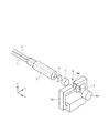
光通信分野等では、透過光量を制御するための光デバイスである可変光アッテネータを必要とする。可変光アッテネータの一例として、特許文献1等に開示された反射型のタイプがある。この反射型の可変光アッテネータは、入射光が進む方向に光学部品を所定の順に配列して構成される。具体的には、光学部品の配列は、入力ファイバ1と出力ファイバ2を装着した2芯フェルール3の先端外側に、光の入出射面から順に複屈折素子4,光収束性のレンズ(凸レンズ)5,可変偏波回転手段6,反射鏡7を配置した構成を採る。便宜上、光学部品の配列方向(入射光が進む方向)をz方向(図では右方向)とし、それに対して直交する2方向をx方向(水平方向)、y方向(垂直方向)とする。従って、図2(a)は平面を表し、同図(b)は正面を表すことになる。
In the optical communication field and the like, a variable optical attenuator that is an optical device for controlling the amount of transmitted light is required. As an example of the variable optical attenuator, there is a reflection type disclosed in
入力ファイバ1と出力ファイバ2は、x方向に並べて平行に配置する。ここでは、z方向を見て右側光路に入力ファイバ1を配置し、左側光路に出力ファイバ2を配置する構成を採る。複屈折素子4は、z方向に向かう偏波方向が直交関係にある同じ光路の光をy方向に分離し−z方向に向かう異なる光路の光を合成する平行平面型の偏波分離合成用の複屈折素子を用いている。反射鏡7は、レンズ5の焦点に配置する。
The
可変偏波回転手段6は、ファラデー回転子6aと、そのファラデー回転子6aに2方向から固定磁界と可変磁界による合成磁界を印加する構成をとる。固定磁界は、反射鏡7の背後に配置した円板状の永久磁石6bによって光が進む方向に印加される。可変磁界は、電磁石6cによって光が進む方向に対して垂直な方向に印加される。これら2つの磁界がファラデー回転子6aに印加され、その合成磁界に応じてファラデー回転子6aのファラデー回転角が変化する。
The variable polarization rotating means 6 has a configuration in which a Faraday
上記の構成を採る反射型可変光アッテネータの動作原理は、以下の通りである。入力ファイバ1から入射した光は、複屈折素子4、レンズ5を通り反射鏡7に集光して反射され、反射戻り光は、再びレンズ5、複屈折素子4を通って出射する。その過程で、光は、可変偏波回転手段6のファラデー回転子6aを往復する。そして、この可変偏波回転手段6で偏波方向の回転角度を制御することにより、反射出力光量を制御する。
The operation principle of the reflective variable optical attenuator having the above configuration is as follows. The light incident from the
つまり入力ファイバ1からz方向に入射する光は、複屈折素子4で常光と異常光とにy方向に光分離する。そしてレンズ5で集光し、その集光途中でファラデー回転子6aを通過する。ファラデー回転角が0度のときは、レンズ焦点位置の反射鏡7では偏波方向は回転せず反射する。−z方向に戻る反射光は、再びファラデー回転子6a及びレンズ5を通過するが、その際も偏波方向は回転しない。ただし、反射光の常光と異常光の位置は、xy平面において焦点位置を中心に対角位置にずれる。そして、複屈折素子4では、すべての常光と異常光とがさらにy方向に分離する。従って、入力ファイバ1からの入射光は、ほとんど出力ファイバ2には結合しない。つまり、入力ファイバ1からの入射光量のほとんど全てが減衰することになる。
That is, the light incident in the z direction from the
一方、ファラデー回転角が45度に設定されているときは、光はレンズ焦点位置の反射鏡7では偏波方向が45度回転して反射する。このとき、常光と異常光の位置は、xy平面において焦点位置を中心に対角位置にずれる。−z方向に戻る反射光は、再びファラデー回転子6a及びレンズ5を通過し、その際に偏波方向が更に45度(従って合計で90度)回転する。そして、複屈折素子4では、90度回転され、さらに対角位置にずれた常光と異常光とがy方向に偏波合成する。このようにして、入力ファイバ1からの入射光は、ほとんど減衰することなくほぼ全量が出力ファイバ2へと出射する。
On the other hand, when the Faraday rotation angle is set to 45 degrees, the light is reflected by the
さらに、電磁石6cにより発生する磁界を調整することで、可変偏波回転手段6によって偏波方向を任意の角度に回転させることができる。例えば、22.5度回転するように調整すると、光はレンズ焦点位置の反射鏡7では偏波方向が22.5度回転して反射する。−z方向に戻る反射光は、再びファラデー回転子6a及びレンズ12を通過し、その際にも偏波方向が更に同じ角度である22.5度回転し、合計で45度回転する。すると複屈折素子4で、一部の常光と異常光はy方向に偏波合成され出力ファイバ2に結合するが、残りの常光と異常光は更にy方向に偏波分離するため出力ファイバには結合しない。従って、ファラデー回転角を22.5度に設定した場合は、入力ファイバ1からの入射光は減衰し、入射光量がほぼ半減して出力ファイバ2へ出射する。このように可変偏波回転手段6で偏波方向の回転角度を制御することによって、入射光の減衰量(言い換えれば反射出力光量)を自由に調整できることになる。
Furthermore, by adjusting the magnetic field generated by the
上述した従来の構成では、ファラデー回転子6aに光の透過方向(z方向)に永久磁石6bから発生される固定磁界を印加し、電磁石6cにより発生する可変磁界をファラデー回転子6aの面内方向(x方向)に印加する構成を採る。そして、各磁界発生手段が入射光並びに反射光の光路の邪魔をしないようにするために、永久磁石6bは、反射鏡7の外側に配置することになり、フェライト系の永久磁石等の磁力の弱い永久磁石を用いてファラデー回転子6aを磁気飽和させようとすると、体積の大きなものが必要となり、装置の大型化を招く。そのため磁力の強いサマリウムコバルト磁石やネオジム磁石といった希土類の永久磁石を用いている。しかし、希土類磁石は錆びる材料であるため、防錆処理が必要となる。
In the conventional configuration described above, a fixed magnetic field generated from the
さらに、ファラデー回転角は、固定磁界と可変磁界とによって作られる合成磁界により制御されるが、可変磁界に対して固定磁界が相対的に大きすぎると、微少な回転角しか生じさせることができない。そのため、両方の磁界の強さを合わせる必要がある。そして、希土類磁石は磁束密度の高い材料であることから、永久磁石による飽和磁界はファラデー回転子を磁気飽和させるのに必要十分な程度に抑えるために、ファラデー回転子6aから比較的離れた位置に配置したり、永久磁石を極力小さくしたりする必要がある。そうすると、前者の比較的離れた位置に配置する場合には、装置全体が大きくなり、小型化の弊害を来す。また、後者の永久磁石の形状を小さくしようとした場合、希土類磁石は脆いため、薄板などへの微小な加工は難しい。
Furthermore, although the Faraday rotation angle is controlled by a combined magnetic field generated by a fixed magnetic field and a variable magnetic field, if the fixed magnetic field is too large relative to the variable magnetic field, only a very small rotation angle can be generated. Therefore, it is necessary to match both magnetic field strengths. Since the rare earth magnet is a material having a high magnetic flux density, the saturation magnetic field generated by the permanent magnet is positioned relatively far from the Faraday
また、可変磁界をある程度大きくするためには、電磁石6cの磁気回路を構成するコア6c′として、透磁率の高い材料を用いたり、コイルの巻数を多くすることが考えられる。しかし、透磁率の高い材料は錆びる材料であり、やはり防錆処理が必要となる。またコイルの巻数を多くすることにはある程度限界もあり、また、装置の大型化を招く。
In order to increase the variable magnetic field to some extent, it is conceivable to use a material with high magnetic permeability or increase the number of turns of the coil as the
本発明はファラデー回転子を磁気飽和させる手段等を小型化・簡素化した反射型可変光アッテネータを提供する。 The present invention provides a reflective variable optical attenuator in which means for magnetically saturating a Faraday rotator is miniaturized and simplified.
上記の課題を解決するため、本発明の反射型光アッテネータは、光軸に沿って光入出力部、ファラデー回転子を備えた光減衰機構部、反射体をその順で配置して構成される反射型可変光アッテネータであって、前記光減衰機構部は、前記ファラデー回転子に対し、磁気飽和させるために面内方向に固定磁界を印加する永久磁石と、前記ファラデー回転子に対して光軸方向に可変磁界を印加する可変磁界発生手段とを備え、前記永久磁石は、前記ファラデー回転子の光軸と交差する方向の側面に対向して配置することを前提とする。光入出力部は、実施形態では、2芯フェルールや、偏光子と検光子の機能を兼用した複屈折素子11等を含む。光減衰機構部は、実施形態の可変偏波回転手段14に対応する。
In order to solve the above problems, the reflection type optical attenuator of the present invention is configured by arranging a light input / output unit, a light attenuation mechanism unit including a Faraday rotator, and a reflector in that order along the optical axis. A reflection-type variable optical attenuator, wherein the optical attenuation mechanism unit includes a permanent magnet that applies a fixed magnetic field in an in-plane direction to magnetically saturate the Faraday rotator, and an optical axis for the Faraday rotator. Variable magnetic field generating means for applying a variable magnetic field in the direction, and the permanent magnet is assumed to be disposed to face a side surface in a direction intersecting the optical axis of the Faraday rotator. In the embodiment, the light input / output unit includes a two-core ferrule, a
ファラデー回転子を磁気飽和させるためのバイアス磁界(固定磁界)を印加する方向を面内方向としたため、永久磁石は、光軸から外れたファラデー回転子の外側側面に対向する位置に近接配置できる。また、可変磁界発生手段は、コイルその他の電磁石等を用いて実現できるが、ファラデー回転子に対して光軸方向に磁界を印加するため、例えば、ファラデー回転子の周囲を囲むように配置した筒状のコイル等で実現できる。よって、図1等に示した従来のものと比較しても磁界を印加するための手段をコンパクトにまとめることができ、装置の小型化が図れる。また、永久磁石をファラデー回転子に接近させることから、透磁率の小さい微小な磁界を発生させる永久磁石を用いることができる。例えば、フェライト系の磁石など、安価で容易に入手できるので好ましい。 Since the direction in which the bias magnetic field (fixed magnetic field) for magnetic saturation of the Faraday rotator is applied is the in-plane direction, the permanent magnet can be disposed close to the position facing the outer side surface of the Faraday rotator off the optical axis. The variable magnetic field generating means can be realized by using a coil or other electromagnet. However, in order to apply a magnetic field in the optical axis direction to the Faraday rotator, for example, a cylinder arranged so as to surround the Faraday rotator. It can be realized by a coil or the like. Therefore, the means for applying the magnetic field can be compactly compared with the conventional one shown in FIG. 1 and the like, and the apparatus can be miniaturized. Further, since the permanent magnet is brought close to the Faraday rotator, it is possible to use a permanent magnet that generates a minute magnetic field with a small magnetic permeability. For example, ferrite magnets are preferable because they are inexpensive and easily available.
(1)上記の前提のもと、前記永久磁石はフェライト系永久磁石であり、前記可変磁界発生手段は空芯コイルであり、前記空芯コイルの内部空間内に前記ファラデー回転子と前記永久磁石を配置するようにした。フェライト系永久磁石は、錆びないので防錆処理が不要で簡易に製造できる。また空芯コイルとすることでコア等もなく簡易な構成となる。 (1) Under the above premise, the permanent magnet is a ferrite permanent magnet, the variable magnetic field generating means is an air core coil, and the Faraday rotator and the permanent magnet are disposed in an internal space of the air core coil. It was to be placed. Ferrite permanent magnets do not rust, and therefore can be manufactured easily without the need for rust prevention treatment. Moreover, it becomes a simple structure without a core etc. by setting it as an air core coil.
(2)上記の前提のもと、前記ファラデー回転子は希土類鉄ガーネット単結晶であり、前記固定磁界の印加方向が前記ファラデー回転子の<211>方向で、前記可変磁界の印加方向が前記ファラデー回転子の<111>方向とするようにした。ファラデー回転子の<211>方向は磁気飽和しやすい方向であるため、より小さい磁場(例えば100エルステッド以下)で磁気飽和させることができる。それに伴い、ファラデー回転角を回転させるための可変磁界も小さい磁力ですむ。よって、より小型な構成で実現できる。 (2) Under the above premise, the Faraday rotator is a rare earth iron garnet single crystal, the application direction of the fixed magnetic field is the <211> direction of the Faraday rotator, and the application direction of the variable magnetic field is the Faraday rotator. The <111> direction of the rotor was set . Since the <211> direction of the Faraday rotator is a direction in which magnetic saturation is likely to occur, magnetic saturation can be achieved with a smaller magnetic field (for example, 100 oersted or less). Along with this, the variable magnetic field for rotating the Faraday rotation angle requires only a small magnetic force. Therefore, it can be realized with a smaller configuration.
(3)上記の前提のもと、前記ファラデー回転子は希土類鉄ガーネット単結晶であり、前記固定磁界の印加方向が前記ファラデー回転子の<211>方向から5から20度の範囲とし、前記可変磁界の印加方向が前記ファラデー回転子の<111>方向とするようにした。5度よりも小さい範囲は、損失が大きくなり、20度より大きくなると飽和磁界が150エルステッドより大きくなる。よって、要求される仕様が厳しくなると、係る範囲とするのがよい。
(4)上記の(2),(3)の発明を前提とし、前記永久磁石はフェライト系永久磁石であり、前記可変磁界発生手段は空芯コイルであり、前記空芯コイルの内部空間内に前記ファラデー回転子と前記永久磁石を配置するようにするとよい。
(3) Under the above premise, the Faraday rotator is a rare earth iron garnet single crystal, the application direction of the fixed magnetic field is in the range of 5 to 20 degrees from the <211> direction of the Faraday rotator, and the variable application direction of magnetic field is set as the <111> direction of the Faraday rotator. In the range smaller than 5 degrees, the loss increases, and when it exceeds 20 degrees, the saturation magnetic field becomes larger than 150 oersted. Therefore, when the required specification becomes strict, it is preferable to set the range.
(4) On the premise of the above inventions (2) and (3), the permanent magnet is a ferrite permanent magnet, the variable magnetic field generating means is an air-core coil, The Faraday rotator and the permanent magnet may be arranged.
(5)前記光軸上に配置する回転角補正用ファラデー回転子と、その回転角補正用ファラデー回転子のファラデー回転角を設定する磁界印加手段を備え、前記可変磁界がゼロのときに、前記光入出力部から入力した入射光が前記反射体で反射して戻ってきた反射光が、前記光入出力部から100%出力或いは遮断されるように前記ファラデー回転子のファラデー回転角と、前記回転角補正用ファラデー回転子のファラデー回転角が設定されるとよい。このようにすると、光減衰機構部を構成するファラデー回転子単独で所望のファラデー回転角の範囲が得られない場合でも、回転角補正用ファラデー回転子のファラデー回転角を適宜に設定することで反射型可変光アッテネータ全体で所望の特性が得られる。 (5) a rotation angle correcting Faraday rotator disposed on the optical axis, and a magnetic field applying means for setting a Faraday rotation angle of the rotation angle correcting Faraday rotator, and when the variable magnetic field is zero, The Faraday rotation angle of the Faraday rotator so that the incident light input from the light input / output unit is reflected or returned by the reflector and is 100% output or blocked from the light input / output unit; The Faraday rotation angle of the Faraday rotator for rotation angle correction may be set. In this way, even if the desired Faraday rotator angle range cannot be obtained with the Faraday rotator constituting the light attenuation mechanism unit alone, reflection is achieved by appropriately setting the Faraday rotator angle of the rotation angle correcting Faraday rotator. Desired characteristics can be obtained with the entire variable optical attenuator.
本発明では、ファラデー回転子を磁気飽和させる手段を小型化・簡素化でき、それに伴い可変磁界を印加する構成も簡素化できる。さらに、ファラデー回転子として希土類鉄ガーネット単結晶を用いた場合、ファラデー回転子の磁気飽和方向をファラデー回転子の<211>方向にすることで、飽和磁界を小さくすることができる。これによって飽和磁界を発生させる手段を防錆処理の必要な希土類磁石から防錆処理の必要のないフェライト系の永久磁石を用いることができる。さらに飽和磁界が小さいので、可変磁界も小さくすることができ、可変磁界を発生させる手段として、透磁率の高い材料を用いた磁気回路を必要とせず、小型で安価な反射型可変光アッテネータを提供できる。 In the present invention, the means for magnetic saturation of the Faraday rotator can be reduced in size and simplified, and the configuration for applying a variable magnetic field can be simplified accordingly. Further, when a rare earth iron garnet single crystal is used as the Faraday rotator, the saturation magnetic field can be reduced by setting the magnetic saturation direction of the Faraday rotator to the <211> direction of the Faraday rotator. As a result, a means for generating a saturation magnetic field can be used from a rare earth magnet that requires rust prevention treatment to a ferrite permanent magnet that does not require rust prevention treatment. In addition, since the saturation magnetic field is small, the variable magnetic field can be reduced, and as a means for generating the variable magnetic field, a reflective variable optical attenuator is provided that is small and inexpensive without requiring a magnetic circuit using a material with high magnetic permeability. it can.
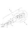
以下、本発明の好適な実施形態について説明する。図3は、本発明に係る反射型可変光アッテネータ10の好適な一実施形態を示している。本実施形態の反射型可変光アッテネータ10は、図示省略する2芯フェルールで構成される入出力ポートに対向するように複屈折素子11を配置し、その複屈折素子11の後側に入力ポート(入力ファイバ)から入射される入射光が進む方向に沿って、回転角補正用ファラデー回転子12,光収束性のレンズ13,可変偏波回転手段14,反射体15をその順に配置する。
Hereinafter, preferred embodiments of the present invention will be described. FIG. 3 shows a preferred embodiment of the reflective variable
図示省略した2芯フェルールは、図1に示した従来のものと同様の構成を採ることができる。つまり、入射光の進む方向をz方向とし、そのz方向と直交する水平方向をx方向で垂直方向をy方向とすると、入力ファイバと出力ファイバはx方向に平行に並ぶように配置し、その先端を2芯フェルールに装着し、入出力ポートの位置を特定する。複屈折素子11は、ルチル単結晶から構成し、偏光子及び検光子としての機能を有する。この複屈折素子11は、特許文献1等に開示された従来のものと基本的に同様のものを用いることができる。レンズ13も凸レンズ等を用い、その焦点位置に反射体15を配置する。これらの基本構成は、従来と同様であるので、その詳細な説明を省略する。
The two-core ferrule (not shown) can have the same configuration as the conventional one shown in FIG. In other words, when the direction in which incident light travels is the z direction, the horizontal direction orthogonal to the z direction is the x direction and the vertical direction is the y direction, the input fiber and the output fiber are arranged in parallel to the x direction. Attach the tip to the 2-core ferrule and specify the position of the input / output port. The
回転角補正用ファラデー回転子12は、円筒状の永久磁石17の軸方向に形成された貫通孔内に挿入配置され、その永久磁石17の磁力により磁気飽和している。可変磁界がない単調増加型の光減衰器では、回転角補正用ファラデー回転子12とファラデー回転子20を往復した光の偏波面が90度回転された後、複屈折素子11で100%結合されて、出力ポートへ出力される。
The rotation angle correcting
ここで本発明では、可変偏波回転手段14の構成要素を以下のようにした。すなわち、まず、従来と同様に入射光が進む光路と直交するように扁平矩形状のファラデー回転子20を配置する。
Here, in the present invention, the components of the variable
さらに、ファラデー回転子20に直交する2方向から固定磁界と可変磁界による合成磁界を印加する構成をとる。そして固定磁界H1は、ファラデー回転子20を磁気飽和させるための磁界であってファラデー回転子20の面内方向に印加し、可変磁界H2は、ファラデー回転子20のファラデー回転角を制御するための磁界であってファラデー回転子20の光軸方向(z方向)に印加するように設定する(図4(a)参照)。ファラデー回転角は、固定磁界H1と可変磁界H2の合成磁界により決定される合成回転角αにより決定され、可変磁界H2の強さを変化させることで制御できる(図4(b)参照)。
Further, a combined magnetic field by a fixed magnetic field and a variable magnetic field is applied from two directions orthogonal to the
これら各磁界を印加するための具体的な構成は、ファラデー回転子20の水平方向左右両側に一対の永久磁石21を配置する。この一対の永久磁石21は、平板状であってファラデー回転子20の側面に対向する全面がS極或いはN極となる。よって、一方の永久磁石のファラデー回転子20の対向面をN極にし、他方の永久磁石の対向面をS極にすることで、一対の永久磁石21間で発生する固定磁界H1が、ファラデー回転子20の面内方向に印加される。
As a specific configuration for applying each of these magnetic fields, a pair of
図から明らかなように、一対の永久磁石21は、ファラデー回転子20の側面外側に配置させることから、どの位置に配置しても入射光,反射光の光路の外になる。よって、永久磁石21はファラデー回転子20に近接配置することができ、小さい磁力でもファラデー回転子20を磁気飽和させることができる。そのため、本実施形態では、磁力の小さいフェライト系の永久磁石を用いて構成することが可能である。フェライト系の永久磁石は、錆びないので防錆処理をしなくてもよく、しかも安価であるので、可変偏波回転手段14ひいては反射型可変光アッテネータ10の製造を容易かつ安価に行える。
As is apparent from the figure, the pair of
また、永久磁石21によりファラデー回転子20に印加するバイアス磁界が小さくなるので、小さい可変磁界H2でも十分な量だけファラデー回転角を回転させることができる。そこで、空芯コイルからなるソレノイドコイル22にてファラデー回転子20に可変磁界H2を印加するようにした。つまり、円筒状のソレノイドコイル22の内部空間内に、そのソレノイドコイル22の軸心とファラデー回転子20の光軸が一致するように当該ファラデー回転子20を配置する。これにより、ソレノイドコイル22に電流を流すと、ソレノイドコイル22の内部空間内を軸心に沿って磁界が発生するため、ファラデー回転子20の光軸(z方向)に磁界を印加することができる。そして、ソレノイドコイル22への通電量を制御することで、可変磁界H2の磁界の強さを制御できる。なお、本実施形態では、永久磁石21をファラデー回転子20に近接配置していることから、その永久磁石21もソレノイドコイル22の内部空間内に配置する。
Further, since the bias magnetic field applied to the
可変磁界H2を印加するための手段が、空芯コイルからなるソレノイドコイル22で実現できるので、従来のように透磁率の高いコアも不要となり、通電量を小さくできることも相まって、可変磁界H2を印加するための磁界発生手段も、小型で簡易な構成にできるとともに、特別な防錆処理も不要となる。
Since the means for applying the variable magnetic field H2 can be realized by the
よって、固定磁界と可変磁界のいずれも小さい磁界を発生させ、小さい磁界による合成磁界でファラデー回転子20の回転角を回転させるので、可変磁界の磁力の制御・調整も瞬時にでき、反射型可変光アッテネータ10はより高速応答が可能となる。しかも、可変偏波回転手段14は、上述したようにバイアス磁界となる固定磁界H1を印加するための永久磁石21は、ファラデー回転子20に近接配置し、そのファラデー回転子20と永久磁石21の周囲を覆うようにソレノイドコイル22を配置する構造を採るので、その全体の外形寸法形状は、ソレノイドコイル22の外形状と一致するため、コンパクトに纏まり、小型化が図れる。さらに、通電量を小さくできるので、反射型可変光アッテネータ10の消費電力も低減することができる。
Therefore, both the fixed magnetic field and the variable magnetic field generate a small magnetic field, and the rotation angle of the
本実施形態の反射型可変光アッテネータ10の動作原理は、図2を用いて説明した従来のものと基本的に同様である。つまり、可変偏波回転手段14における固定磁界H1と可変磁界H2を印加するための手段は従来と異なるものの、それによりファラデー回転子20のファラデー回転角が回転し、所望のファラデー回転角にすることができる。これにより、反射光を100%出力ポートから出力させたり、全く出力させなかったり、それらの中間の適宜の減衰量で出力させたりすることができる。
The operating principle of the reflective variable
さらに本実施形態では、ファラデー回転子として希土類鉄ガーネット単結晶を使用し、図4(a)に示すように、永久磁石21によりファラデー回転子20に印加する固定磁界H1(バイアス磁界)の方向がファラデー回転子の<211>方向となり、ソレノイドコイル22により印加する可変磁界H2の方向がファラデー回転子の<111>方向となるように設定する。すなわち、ファラデー回転子を構成する希土類鉄ガーネット単結晶について光線方向と直交方向である面内方向の飽和磁界強度を調査したところ、<211>方向が最も小さいことが確認できた。よって、固定磁界H1が飽和磁界強度の小さい<211>方向に印加するように調整することで、永久磁石21の磁力はより小さくすることができ、より小型にすることができる。さらに、それに伴い可変磁界H2から発生する磁力も小さくすることができる。
Furthermore, in this embodiment, a rare earth iron garnet single crystal is used as the Faraday rotator, and the direction of the fixed magnetic field H1 (bias magnetic field) applied to the
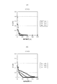
図5(a)は、<211>方向に面内磁界が印加されるようにした場合の磁界−散乱ロス特性を示しており、図5(b)は<110>方向に面内磁界が印加されるようにした場合の磁界−散乱ロス特性を示している。散乱ロス(ΔL)が0になると磁気飽和しているといえるので、<211>方向のものでは、−10℃から75℃の通常の使用環境において100エルステッド程度の磁場の強さがあると磁気飽和することが確認できる。これに対し、<110>方向の場合、75℃といった高温度の環境では100エルステッド程度の磁場強度で磁気飽和するが、室温(25℃)や−10度の低温度の環境を考慮すると、300エルステッドは必要となる。 FIG. 5A shows magnetic field-scattering loss characteristics when an in-plane magnetic field is applied in the <211> direction, and FIG. 5B shows an in-plane magnetic field applied in the <110> direction. The magnetic field-scattering loss characteristic in the case of being made is shown. When the scattering loss (ΔL) becomes zero, it can be said that the magnetic saturation occurs. Therefore, in the <211> direction, the magnetic field is about 100 oersted in a normal use environment of −10 ° C. to 75 ° C. Saturation can be confirmed. On the other hand, in the <110> direction, magnetic saturation occurs at a magnetic field strength of about 100 oersted in a high temperature environment such as 75 ° C., but considering a low temperature environment of room temperature (25 ° C.) or −10 degrees, 300 Oersted is needed.
図6は、バイアス磁界となる固定磁界H1が100エルステッドの場合と300エルステッドのそれぞれの場合における可変磁界H2に対する合成回転角の特性を示している。当然のことながら、固定磁界H1=可変磁界H2のときに合成回転角は45度となり、固定磁界H1が小さいほど可変磁界の変化に対する合成回転角の変化量は大きくなる。換言すると、合成回転角の角度範囲を同じ範囲にするためには、固定磁界H1が小さいほど可変磁界H2の変更範囲は小さくて済む。 FIG. 6 shows the characteristics of the combined rotation angle with respect to the variable magnetic field H2 when the fixed magnetic field H1 serving as the bias magnetic field is 100 oersted and 300 oersted. Naturally, the combined rotation angle is 45 degrees when the fixed magnetic field H1 = the variable magnetic field H2, and the smaller the fixed magnetic field H1, the larger the amount of change in the combined rotation angle with respect to the change in the variable magnetic field. In other words, in order to make the angle range of the combined rotation angle the same range, the smaller the fixed magnetic field H1, the smaller the change range of the variable magnetic field H2.
よって、本実施形態のように、<211>方向に固定磁界H1を印加する構成とすることで、<110>方向の場合に固定磁界H1を印加するものに比べて永久磁石21並びにソレノイドコイル22のそれぞれの磁界発生手段により生じさせる磁力を小さく抑えることができる。
Therefore, as in the present embodiment, the configuration in which the fixed magnetic field H1 is applied in the <211> direction allows the
上記の実施形態では、固定磁界H1の磁界印加方向を<211>方向としたが、<211>方向から5から20度の範囲とするとよりよい。すなわち、<211>方向は、上記のように飽和磁界が小さくて済むので好ましいが、磁界変位経路中に困難軸があり、消光比が劣化する。具体的には、最大減衰量が30dBを下回ることがある。従って、要求される仕様によっては<211>方向のままでは使用できない場合がある。一方、成就したように、<110>方向では、飽和磁界が大きいものの消光比は劣化しない。そこで、<211>方向から<110>方向の間で磁界の印加方向の角度を変えてファラデー回転子に固定磁界を印加し、そのときの挿入損失(飽和磁界)と消光比(最大減衰量)を測定した。その結果、飽和磁界については、図8(a)のような結果が得られ、最大減衰量については図8(b)に示す結果が得られた。 In the above embodiment, the magnetic field application direction of the fixed magnetic field H1 is the <211> direction. However, it is better to set the magnetic field application direction in the range of 5 to 20 degrees from the <211> direction. That is, the <211> direction is preferable because the saturation magnetic field is small as described above, but there is a difficult axis in the magnetic field displacement path, and the extinction ratio is deteriorated. Specifically, the maximum attenuation may be less than 30 dB. Therefore, depending on the required specifications, the <211> direction may not be used. On the other hand, as realized, in the <110> direction, although the saturation magnetic field is large, the extinction ratio does not deteriorate. Therefore, a fixed magnetic field is applied to the Faraday rotator by changing the angle of the magnetic field application direction between the <211> direction and the <110> direction, and the insertion loss (saturation magnetic field) and extinction ratio (maximum attenuation) at that time are applied. Was measured. As a result, the result shown in FIG. 8A was obtained for the saturation magnetic field, and the result shown in FIG. 8B was obtained for the maximum attenuation.
図から明らかなように、要求される仕様が−10℃〜75℃の温度範囲内で挿入損失が永久磁石の磁界の150エルステッド以下とすると、<211>方向からの角度が20度以下が上限となる。同様に100エルステッド以下が要求される場合には、15度以下(より確実には10度以下)が好ましい範囲内となる。一方、消光比(最大減衰量)が30dB以上が要求される仕様では、<211>方向からの角度が5度以上であることが下限となる。よって、上述した<211>方向から5から20度の範囲がより良い範囲といえる。 As is apparent from the figure, if the required specification is within a temperature range of −10 ° C. to 75 ° C. and the insertion loss is 150 oersted or less of the magnetic field of the permanent magnet, the angle from the <211> direction is 20 degrees or less. It becomes. Similarly, when 100 oersted or less is required, 15 degrees or less (more surely 10 degrees or less) is within the preferable range. On the other hand, in a specification that requires an extinction ratio (maximum attenuation) of 30 dB or more, the lower limit is that the angle from the <211> direction is 5 degrees or more. Therefore, it can be said that the range of 5 to 20 degrees from the <211> direction described above is a better range.
10 反射型可変光アッテネータ
11 複屈折素子
12 回転角補正用ファラデー回転子
13 レンズ
14 可変偏波回転手段
15 反射体
20 ファラデー回転子
21 永久磁石
22 ソレノイドコイル
DESCRIPTION OF
Claims (5)
前記光減衰機構部は、前記ファラデー回転子に対し、磁気飽和させるために面内方向に固定磁界を印加する永久磁石と、前記ファラデー回転子に対して光軸方向に可変磁界を印加する可変磁界発生手段とを備え、
前記永久磁石は、前記ファラデー回転子の光軸と交差する方向の側面に対向して配置し、
前記永久磁石はフェライト系永久磁石であり、
前記可変磁界発生手段は空芯コイルであり、
前記空芯コイルの内部空間内に前記ファラデー回転子と前記永久磁石を配置することを特徴とする反射型可変光アッテネータ。 A reflection-type variable optical attenuator configured by arranging a light input / output unit along the optical axis, a light attenuation mechanism unit including a Faraday rotator, and a reflector in that order,
The light attenuation mechanism includes a permanent magnet that applies a fixed magnetic field in an in-plane direction to magnetically saturate the Faraday rotator, and a variable magnetic field that applies a variable magnetic field in the optical axis direction to the Faraday rotator. Generating means,
The permanent magnet is disposed to face a side surface in a direction intersecting with the optical axis of the Faraday rotator ,
The permanent magnet is a ferrite permanent magnet,
The variable magnetic field generating means is an air-core coil,
A reflection type variable optical attenuator, wherein the Faraday rotator and the permanent magnet are arranged in an internal space of the air-core coil.
前記光減衰機構部は、前記ファラデー回転子に対し、磁気飽和させるために面内方向に固定磁界を印加する永久磁石と、前記ファラデー回転子に対して光軸方向に可変磁界を印加する可変磁界発生手段とを備え、
前記永久磁石は、前記ファラデー回転子の光軸と交差する方向の側面に対向して配置し、
前記ファラデー回転子は希土類鉄ガーネット単結晶であり、前記固定磁界の印加方向が前記ファラデー回転子の<211>方向で、前記可変磁界の印加方向が前記ファラデー回転子の<111>方向とすることを特徴とする反射型可変光アッテネータ。 A reflection-type variable optical attenuator configured by arranging a light input / output unit along the optical axis, a light attenuation mechanism unit including a Faraday rotator, and a reflector in that order,
The light attenuation mechanism includes a permanent magnet that applies a fixed magnetic field in an in-plane direction to magnetically saturate the Faraday rotator, and a variable magnetic field that applies a variable magnetic field in the optical axis direction to the Faraday rotator. Generating means,
The permanent magnet is disposed to face a side surface in a direction intersecting with the optical axis of the Faraday rotator ,
The Faraday rotator is a rare earth iron garnet single crystal, the application direction of the fixed magnetic field is the <211> direction of the Faraday rotator, and the application direction of the variable magnetic field is the <111> direction of the Faraday rotator. Reflective variable optical attenuator.
前記光減衰機構部は、前記ファラデー回転子に対し、磁気飽和させるために面内方向に固定磁界を印加する永久磁石と、前記ファラデー回転子に対して光軸方向に可変磁界を印加する可変磁界発生手段とを備え、
前記永久磁石は、前記ファラデー回転子の光軸と交差する方向の側面に対向して配置し、
前記ファラデー回転子は希土類鉄ガーネット単結晶であり、前記固定磁界の印加方向が前記ファラデー回転子の<211>方向から5から20度の範囲とし、前記可変磁界の印加方向が前記ファラデー回転子の<111>方向とすることを特徴とする反射型可変光アッテネータ。 A reflection-type variable optical attenuator configured by arranging a light input / output unit along the optical axis, a light attenuation mechanism unit including a Faraday rotator, and a reflector in that order,
The light attenuation mechanism includes a permanent magnet that applies a fixed magnetic field in an in-plane direction to magnetically saturate the Faraday rotator, and a variable magnetic field that applies a variable magnetic field in the optical axis direction to the Faraday rotator. Generating means,
The permanent magnet is disposed to face a side surface in a direction intersecting with the optical axis of the Faraday rotator ,
The Faraday rotator is a rare earth iron garnet single crystal, the application direction of the fixed magnetic field is in the range of 5 to 20 degrees from the <211> direction of the Faraday rotator, and the application direction of the variable magnetic field is the Faraday rotator. A reflection-type variable optical attenuator having a <111> direction.
前記可変磁界発生手段は空芯コイルであり、The variable magnetic field generating means is an air-core coil,
前記空芯コイルの内部空間内に前記ファラデー回転子と前記永久磁石を配置することを特徴とする請求項2または3に記載の反射型可変光アッテネータ。The reflection type variable optical attenuator according to claim 2 or 3, wherein the Faraday rotator and the permanent magnet are arranged in an internal space of the air-core coil.
前記可変磁界がゼロのときに、前記光入出力部から入力した入射光が前記反射体で反射して戻ってきた反射光が、前記光入出力部から100%出力或いは遮断されるように前記ファラデー回転子のファラデー回転角と、前記回転角補正用ファラデー回転子のファラデー回転角が設定されることを特徴とする請求項1から4のいずれか1項に記載の反射型可変光アッテネータ。 A rotation angle correcting Faraday rotator disposed on the optical axis, and a magnetic field applying means for setting a Faraday rotation angle of the rotation angle correcting Faraday rotator,
When the variable magnetic field is zero, the incident light input from the light input / output unit is reflected by the reflector and returned, so that the reflected light is output or blocked from the light input / output unit by 100%. The reflection type variable optical attenuator according to any one of claims 1 to 4, wherein a Faraday rotation angle of a Faraday rotator and a Faraday rotation angle of the rotation angle correcting Faraday rotator are set.
Priority Applications (5)
| Application Number | Priority Date | Filing Date | Title |
|---|---|---|---|
| JP2010165006A JP5647828B2 (en) | 2010-07-22 | 2010-07-22 | Reflective variable optical attenuator |
| US13/811,043 US8854716B2 (en) | 2010-07-22 | 2011-06-27 | Reflection type variable optical attenuator |
| DE112011102432T DE112011102432T5 (en) | 2010-07-22 | 2011-06-27 | Variable optical damper of the reflection type |
| PCT/JP2011/064642 WO2012011365A1 (en) | 2010-07-22 | 2011-06-27 | Reflective type variable optical attenuator |
| CN201180035334.7A CN103003738B (en) | 2010-07-22 | 2011-06-27 | Reflective type variable optical attenuator |
Applications Claiming Priority (1)
| Application Number | Priority Date | Filing Date | Title |
|---|---|---|---|
| JP2010165006A JP5647828B2 (en) | 2010-07-22 | 2010-07-22 | Reflective variable optical attenuator |
Publications (2)
| Publication Number | Publication Date |
|---|---|
| JP2012027192A JP2012027192A (en) | 2012-02-09 |
| JP5647828B2 true JP5647828B2 (en) | 2015-01-07 |
Family
ID=45496793
Family Applications (1)
| Application Number | Title | Priority Date | Filing Date |
|---|---|---|---|
| JP2010165006A Active JP5647828B2 (en) | 2010-07-22 | 2010-07-22 | Reflective variable optical attenuator |
Country Status (5)
| Country | Link |
|---|---|
| US (1) | US8854716B2 (en) |
| JP (1) | JP5647828B2 (en) |
| CN (1) | CN103003738B (en) |
| DE (1) | DE112011102432T5 (en) |
| WO (1) | WO2012011365A1 (en) |
Families Citing this family (5)
| Publication number | Priority date | Publication date | Assignee | Title |
|---|---|---|---|---|
| US10705804B2 (en) * | 2012-02-26 | 2020-07-07 | Logistics Research Centre SIA | Strongly typed metadata access in object oriented programming languages with reflection support |
| JP6340176B2 (en) | 2013-08-09 | 2018-06-06 | 湖北工業株式会社 | Optical device |
| JP6578118B2 (en) * | 2014-04-04 | 2019-09-18 | 株式会社ニューフレアテクノロジー | Imaging apparatus, inspection apparatus, and inspection method |
| CN103996966B (en) * | 2014-05-26 | 2016-08-31 | 浙江大学城市学院 | All-optical switch based on rubidium atomic light filter and method thereof |
| FI129636B (en) * | 2019-05-03 | 2022-06-15 | Teknologian Tutkimuskeskus Vtt Oy | Polarization rotator |
Family Cites Families (9)
| Publication number | Priority date | Publication date | Assignee | Title |
|---|---|---|---|---|
| JPH01230498A (en) * | 1988-03-09 | 1989-09-13 | Furukawa Electric Co Ltd:The | Method for forming garnet membrane |
| JPH11199390A (en) * | 1998-01-06 | 1999-07-27 | Fuji Elelctrochem Co Ltd | Production of faraday element |
| JP3974041B2 (en) * | 2001-05-07 | 2007-09-12 | 富士通株式会社 | Optical variable attenuator, optical shutter and optical variable equalizer |
| US6580546B2 (en) * | 2001-08-03 | 2003-06-17 | Primanex | Faraday rotator |
| JP3771228B2 (en) * | 2002-08-12 | 2006-04-26 | Tdk株式会社 | Magneto-optical components |
| JP4382344B2 (en) * | 2002-11-27 | 2009-12-09 | Fdk株式会社 | Reflective variable magneto-optical device |
| JP2005208295A (en) * | 2004-01-22 | 2005-08-04 | Fdk Corp | Variable faraday rotator, and variable optical attenuator using the same |
| JP4655835B2 (en) * | 2005-09-05 | 2011-03-23 | 住友金属鉱山株式会社 | Faraday rotation angle variable device |
| JP2007199112A (en) * | 2006-01-23 | 2007-08-09 | Fdk Corp | Reflection type optical attenuator |
-
2010
- 2010-07-22 JP JP2010165006A patent/JP5647828B2/en active Active
-
2011
- 2011-06-27 WO PCT/JP2011/064642 patent/WO2012011365A1/en active Application Filing
- 2011-06-27 US US13/811,043 patent/US8854716B2/en active Active
- 2011-06-27 DE DE112011102432T patent/DE112011102432T5/en not_active Withdrawn
- 2011-06-27 CN CN201180035334.7A patent/CN103003738B/en active Active
Also Published As
| Publication number | Publication date |
|---|---|
| WO2012011365A1 (en) | 2012-01-26 |
| CN103003738A (en) | 2013-03-27 |
| DE112011102432T5 (en) | 2013-05-08 |
| JP2012027192A (en) | 2012-02-09 |
| US20130120824A1 (en) | 2013-05-16 |
| US8854716B2 (en) | 2014-10-07 |
| CN103003738B (en) | 2016-10-26 |
Similar Documents
| Publication | Publication Date | Title |
|---|---|---|
| JP5647828B2 (en) | Reflective variable optical attenuator | |
| JP3771228B2 (en) | Magneto-optical components | |
| US7379226B2 (en) | Variable optical attenuator | |
| WO2015156190A1 (en) | Light adjustment device | |
| JP2005099737A (en) | Magnetooptic optical component | |
| JP4863371B2 (en) | Faraday rotation angle variable device and variable optical attenuator using the same | |
| JP2003098500A (en) | Reflection type variable optical attenuator | |
| JP2002258229A (en) | Optical attenuator | |
| JPS5828561B2 (en) | optical isolator | |
| JP6340176B2 (en) | Optical device | |
| JP2007199112A (en) | Reflection type optical attenuator | |
| JP4972982B2 (en) | Polarization control device and polarization operation device | |
| JP2005208295A (en) | Variable faraday rotator, and variable optical attenuator using the same | |
| JPWO2004029698A1 (en) | Variable polarization rotator and variable optical attenuator using the same | |
| JP3376529B2 (en) | Optical isolator | |
| JP4931070B2 (en) | Variable optical attenuator | |
| JP2007047359A (en) | Optical device | |
| JP2001091749A (en) | Optical attenuator | |
| JP2005265901A (en) | Optical component | |
| JP3936451B2 (en) | Optical attenuator module | |
| JP2006243039A (en) | Magneto-optic optical component | |
| JP2005049610A (en) | Optical component | |
| JP2002148578A (en) | Faraday rotation device and optical device which uses the same | |
| JP2004355037A (en) | Optical device using magneto-optical effect | |
| JPH04247423A (en) | Optical isolator |
Legal Events
| Date | Code | Title | Description |
|---|---|---|---|
| A621 | Written request for application examination |
Free format text: JAPANESE INTERMEDIATE CODE: A621 Effective date: 20130621 |
|
| A131 | Notification of reasons for refusal |
Free format text: JAPANESE INTERMEDIATE CODE: A131 Effective date: 20140514 |
|
| A521 | Request for written amendment filed |
Free format text: JAPANESE INTERMEDIATE CODE: A523 Effective date: 20140626 |
|
| TRDD | Decision of grant or rejection written | ||
| A01 | Written decision to grant a patent or to grant a registration (utility model) |
Free format text: JAPANESE INTERMEDIATE CODE: A01 Effective date: 20141015 |
|
| A61 | First payment of annual fees (during grant procedure) |
Free format text: JAPANESE INTERMEDIATE CODE: A61 Effective date: 20141110 |
|
| R150 | Certificate of patent or registration of utility model |
Ref document number: 5647828 Country of ref document: JP Free format text: JAPANESE INTERMEDIATE CODE: R150 |
|
| S111 | Request for change of ownership or part of ownership |
Free format text: JAPANESE INTERMEDIATE CODE: R313113 |
|
| R350 | Written notification of registration of transfer |
Free format text: JAPANESE INTERMEDIATE CODE: R350 |
|
| R250 | Receipt of annual fees |
Free format text: JAPANESE INTERMEDIATE CODE: R250 |
|
| R250 | Receipt of annual fees |
Free format text: JAPANESE INTERMEDIATE CODE: R250 |
|
| R250 | Receipt of annual fees |
Free format text: JAPANESE INTERMEDIATE CODE: R250 |
|
| R250 | Receipt of annual fees |
Free format text: JAPANESE INTERMEDIATE CODE: R250 |
|
| R250 | Receipt of annual fees |
Free format text: JAPANESE INTERMEDIATE CODE: R250 |
|
| R250 | Receipt of annual fees |
Free format text: JAPANESE INTERMEDIATE CODE: R250 |
|
| R250 | Receipt of annual fees |
Free format text: JAPANESE INTERMEDIATE CODE: R250 |