JP5647636B2 - Water server - Google Patents
Water server Download PDFInfo
- Publication number
- JP5647636B2 JP5647636B2 JP2012046302A JP2012046302A JP5647636B2 JP 5647636 B2 JP5647636 B2 JP 5647636B2 JP 2012046302 A JP2012046302 A JP 2012046302A JP 2012046302 A JP2012046302 A JP 2012046302A JP 5647636 B2 JP5647636 B2 JP 5647636B2
- Authority
- JP
- Japan
- Prior art keywords
- water
- raw water
- container
- raw
- ozone
- Prior art date
- Legal status (The legal status is an assumption and is not a legal conclusion. Google has not performed a legal analysis and makes no representation as to the accuracy of the status listed.)
- Active
Links
- XLYOFNOQVPJJNP-UHFFFAOYSA-N water Substances O XLYOFNOQVPJJNP-UHFFFAOYSA-N 0.000 title claims description 258
- CBENFWSGALASAD-UHFFFAOYSA-N Ozone Chemical compound [O-][O+]=O CBENFWSGALASAD-UHFFFAOYSA-N 0.000 claims description 96
- 239000003651 drinking water Substances 0.000 claims description 60
- 235000020188 drinking water Nutrition 0.000 claims description 60
- 238000001816 cooling Methods 0.000 claims description 5
- 239000008239 natural water Substances 0.000 description 13
- 230000001954 sterilising effect Effects 0.000 description 8
- QVGXLLKOCUKJST-UHFFFAOYSA-N atomic oxygen Chemical compound [O] QVGXLLKOCUKJST-UHFFFAOYSA-N 0.000 description 7
- 229910052760 oxygen Inorganic materials 0.000 description 7
- 239000001301 oxygen Substances 0.000 description 7
- 230000007423 decrease Effects 0.000 description 6
- 238000004659 sterilization and disinfection Methods 0.000 description 6
- 241000048246 Gallicrex cinerea Species 0.000 description 4
- 238000012986 modification Methods 0.000 description 4
- 230000004048 modification Effects 0.000 description 4
- 229920000139 polyethylene terephthalate Polymers 0.000 description 4
- 239000005020 polyethylene terephthalate Substances 0.000 description 4
- 244000052616 bacterial pathogen Species 0.000 description 3
- 230000006837 decompression Effects 0.000 description 3
- 238000010438 heat treatment Methods 0.000 description 3
- 238000005192 partition Methods 0.000 description 3
- 239000010453 quartz Substances 0.000 description 3
- 239000011347 resin Substances 0.000 description 3
- 229920005989 resin Polymers 0.000 description 3
- VYPSYNLAJGMNEJ-UHFFFAOYSA-N silicon dioxide Inorganic materials O=[Si]=O VYPSYNLAJGMNEJ-UHFFFAOYSA-N 0.000 description 3
- XUIMIQQOPSSXEZ-UHFFFAOYSA-N Silicon Chemical compound [Si] XUIMIQQOPSSXEZ-UHFFFAOYSA-N 0.000 description 2
- 230000002238 attenuated effect Effects 0.000 description 2
- 238000000071 blow moulding Methods 0.000 description 2
- 238000004891 communication Methods 0.000 description 2
- 238000009792 diffusion process Methods 0.000 description 2
- 238000002474 experimental method Methods 0.000 description 2
- 239000012212 insulator Substances 0.000 description 2
- QSHDDOUJBYECFT-UHFFFAOYSA-N mercury Chemical compound [Hg] QSHDDOUJBYECFT-UHFFFAOYSA-N 0.000 description 2
- 229910052753 mercury Inorganic materials 0.000 description 2
- -1 polyethylene terephthalate Polymers 0.000 description 2
- 229910052710 silicon Inorganic materials 0.000 description 2
- 239000010703 silicon Substances 0.000 description 2
- 230000008602 contraction Effects 0.000 description 1
- 238000010586 diagram Methods 0.000 description 1
- 229920001973 fluoroelastomer Polymers 0.000 description 1
- 229910052500 inorganic mineral Inorganic materials 0.000 description 1
- 239000000463 material Substances 0.000 description 1
- 238000005259 measurement Methods 0.000 description 1
- 239000011707 mineral Substances 0.000 description 1
- 229920000515 polycarbonate Polymers 0.000 description 1
- 239000004417 polycarbonate Substances 0.000 description 1
- 229920013716 polyethylene resin Polymers 0.000 description 1
- 238000005086 pumping Methods 0.000 description 1
- 238000011012 sanitization Methods 0.000 description 1
- 238000003756 stirring Methods 0.000 description 1
Images


Classifications
-
- B—PERFORMING OPERATIONS; TRANSPORTING
- B67—OPENING, CLOSING OR CLEANING BOTTLES, JARS OR SIMILAR CONTAINERS; LIQUID HANDLING
- B67D—DISPENSING, DELIVERING OR TRANSFERRING LIQUIDS, NOT OTHERWISE PROVIDED FOR
- B67D1/00—Apparatus or devices for dispensing beverages on draught
- B67D1/07—Cleaning beverage-dispensing apparatus
-
- B—PERFORMING OPERATIONS; TRANSPORTING
- B67—OPENING, CLOSING OR CLEANING BOTTLES, JARS OR SIMILAR CONTAINERS; LIQUID HANDLING
- B67D—DISPENSING, DELIVERING OR TRANSFERRING LIQUIDS, NOT OTHERWISE PROVIDED FOR
- B67D1/00—Apparatus or devices for dispensing beverages on draught
- B67D1/0003—Apparatus or devices for dispensing beverages on draught the beverage being a single liquid
- B67D1/0004—Apparatus or devices for dispensing beverages on draught the beverage being a single liquid the beverage being stored in a container, e.g. bottle, cartridge, bag-in-box, bowl
-
- B—PERFORMING OPERATIONS; TRANSPORTING
- B67—OPENING, CLOSING OR CLEANING BOTTLES, JARS OR SIMILAR CONTAINERS; LIQUID HANDLING
- B67D—DISPENSING, DELIVERING OR TRANSFERRING LIQUIDS, NOT OTHERWISE PROVIDED FOR
- B67D1/00—Apparatus or devices for dispensing beverages on draught
- B67D1/08—Details
- B67D1/0857—Cooling arrangements
-
- B—PERFORMING OPERATIONS; TRANSPORTING
- B67—OPENING, CLOSING OR CLEANING BOTTLES, JARS OR SIMILAR CONTAINERS; LIQUID HANDLING
- B67D—DISPENSING, DELIVERING OR TRANSFERRING LIQUIDS, NOT OTHERWISE PROVIDED FOR
- B67D1/00—Apparatus or devices for dispensing beverages on draught
- B67D1/08—Details
- B67D1/10—Pump mechanism
-
- B—PERFORMING OPERATIONS; TRANSPORTING
- B67—OPENING, CLOSING OR CLEANING BOTTLES, JARS OR SIMILAR CONTAINERS; LIQUID HANDLING
- B67D—DISPENSING, DELIVERING OR TRANSFERRING LIQUIDS, NOT OTHERWISE PROVIDED FOR
- B67D1/00—Apparatus or devices for dispensing beverages on draught
- B67D1/08—Details
- B67D1/0895—Heating arrangements
-
- B—PERFORMING OPERATIONS; TRANSPORTING
- B67—OPENING, CLOSING OR CLEANING BOTTLES, JARS OR SIMILAR CONTAINERS; LIQUID HANDLING
- B67D—DISPENSING, DELIVERING OR TRANSFERRING LIQUIDS, NOT OTHERWISE PROVIDED FOR
- B67D1/00—Apparatus or devices for dispensing beverages on draught
- B67D2001/0095—Constructional details
- B67D2001/0096—Means for pressurizing liquid
- B67D2001/0097—Means for pressurizing liquid using a pump
-
- B—PERFORMING OPERATIONS; TRANSPORTING
- B67—OPENING, CLOSING OR CLEANING BOTTLES, JARS OR SIMILAR CONTAINERS; LIQUID HANDLING
- B67D—DISPENSING, DELIVERING OR TRANSFERRING LIQUIDS, NOT OTHERWISE PROVIDED FOR
- B67D1/00—Apparatus or devices for dispensing beverages on draught
- B67D1/07—Cleaning beverage-dispensing apparatus
- B67D2001/075—Sanitising or sterilising the apparatus
-
- B—PERFORMING OPERATIONS; TRANSPORTING
- B67—OPENING, CLOSING OR CLEANING BOTTLES, JARS OR SIMILAR CONTAINERS; LIQUID HANDLING
- B67D—DISPENSING, DELIVERING OR TRANSFERRING LIQUIDS, NOT OTHERWISE PROVIDED FOR
- B67D2210/00—Indexing scheme relating to aspects and details of apparatus or devices for dispensing beverages on draught or for controlling flow of liquids under gravity from storage containers for dispensing purposes
- B67D2210/00002—Purifying means
- B67D2210/00013—Sterilising means
- B67D2210/00023—Oxygenators
Landscapes
- Engineering & Computer Science (AREA)
- Mechanical Engineering (AREA)
- Devices For Dispensing Beverages (AREA)
- Treatment Of Water By Oxidation Or Reduction (AREA)
Description
この発明は、ミネラルウォーター等の飲料水が充填された交換式の原水容器から飲料水を供給するウォーターサーバーに関する。 The present invention relates to a water server for supplying drinking water from a replaceable raw water container filled with drinking water such as mineral water.
従来、主にオフィスや病院などでウォーターサーバーが利用されてきたが、近年、水の安全や健康への関心の高まりから、一般家庭にもウォーターサーバーが普及しつつある。 Conventionally, water servers have been used mainly in offices and hospitals, but in recent years, water servers are becoming widespread in ordinary households due to increasing interest in water safety and health.
このようなウォーターサーバーとして、飲料水を冷却する冷水タンクと、交換式の原水容器と冷水タンクとの間を連通する原水供給路と、その原水供給路に設けられたポンプとを有するものが知られている(例えば特許文献1、2)。
As such a water server, one having a cold water tank that cools drinking water, a raw water supply path that communicates between the replaceable raw water container and the cold water tank, and a pump provided in the raw water supply path is known. (For example,
このウォーターサーバーは、冷水タンク内で冷却された飲料水を、カップ等に注出して使用される。そして、冷水タンク内の水位が下がると、その水位の低下に応じてポンプが作動し、原水容器から冷水タンクに飲料水が供給される。ところが、原水容器の飲料水が残り少なくなると、原水容器内が負圧となって、原水容器から飲料水を汲み出すのが難しくなり、原水容器の飲料水を完全に使い切ることができない場合があることが分かった。 This water server is used by pouring drinking water cooled in a cold water tank into a cup or the like. And if the water level in a cold water tank falls, a pump will operate | move according to the fall of the water level, and drinking water will be supplied to a cold water tank from a raw | natural water container. However, if there is little remaining drinking water in the raw water container, the pressure in the raw water container becomes negative, making it difficult to pump out the drinking water from the raw water container, and the drinking water in the raw water container may not be used up completely. I understood.
そこで、この発明の発明者は、原水容器の飲料水をポンプで汲み出すタイプの上記ウォーターサーバーにおいて、原水容器の飲料水を確実に使い切ることができるようにするために、原水容器内に空気を導入する吸気路を設けたところ、残水量が減少しても収縮しない剛性のある原水容器だけでなく、残水量の減少に伴って収縮する柔軟な原水容器についても、原水容器内の負圧が防止され、この結果、原水容器の飲料水を完全に使い切ることが可能となった。 Therefore, the inventor of the present invention, in the water server of the type that pumps out the drinking water in the raw water container, in order to ensure that the drinking water in the raw water container can be used up reliably, air is supplied into the raw water container. When the intake passage is introduced, not only the rigid raw water container that does not shrink even if the residual water volume decreases, but also the flexible raw water container that shrinks as the residual water volume decreases, the negative pressure in the raw water container is reduced. As a result, the drinking water in the raw water container can be completely used up.
ところが、原水容器内に空気を導入する吸気路を設けた場合、原水容器の飲料水の一部が吸気路に侵入するため、長期にわたってウォーターサーバーを使用したときに、吸気路内で雑菌が繁殖する可能性があることが分かった。また、原水容器と冷水タンクの間を連通する原水供給路内にも雑菌が繁殖する可能性がある。 However, when an intake passage for introducing air into the raw water container is provided, some of the drinking water in the raw water container enters the intake passage, so that when a water server is used for a long period of time, germs propagate in the intake passage. It turns out that there is a possibility. Moreover, there is a possibility that germs will also propagate in the raw water supply path that communicates between the raw water container and the cold water tank.
この発明が解決しようとする課題は、原水容器に接続する流路を殺菌することが可能な衛生的なウォーターサーバーを提供することである。 The problem to be solved by the present invention is to provide a hygienic water server capable of sterilizing a flow path connected to a raw water container.
上記課題を解決するために、この発明の発明者は、飲料水を冷却する冷水タンクと、交換式の原水容器と冷水タンクとの間を連通する原水供給路と、その原水供給路に設けられたポンプと、前記原水容器内に空気を導入する吸気路と、その吸気路に接続されたオゾン発生装置と、前記ポンプの作動時に前記オゾン発生装置でオゾンを発生させる制御を行なう制御部とを有する構成をウォーターサーバーに採用したのである。 In order to solve the above problems, the inventor of the present invention is provided in a cold water tank that cools drinking water, a raw water supply path that communicates between the replaceable raw water container and the cold water tank, and the raw water supply path. A pump, an intake passage for introducing air into the raw water container, an ozone generator connected to the intake passage, and a control unit that controls the ozone generator to generate ozone when the pump is operated. The configuration with this was adopted for the water server.
これにより、ポンプが作動して原水容器の飲料水を汲み出すときに、原水容器内の減圧によって吸気路から原水容器内に空気が流入すると、オゾン発生装置で発生したオゾンが吸気路を流れ、吸気路の内部がオゾン殺菌される。そのため、吸気路内での雑菌の繁殖が防止され、衛生的である。 As a result, when the pump is activated and the drinking water in the raw water container is pumped out, if air flows into the raw water container from the intake passage due to the decompression in the raw water container, the ozone generated in the ozone generator flows through the intake passage, The inside of the intake passage is sterilized with ozone. Therefore, the propagation of various germs in the intake passage is prevented and it is hygienic.
また、前記制御部は、前記原水容器内に飲料水が無くなったときに、前記ポンプを継続して作動させることで前記吸気路および原水供給路内にオゾンを通過させる制御を行なうようにすると好ましい。 Further, it is preferable that the control unit performs control to allow ozone to pass through the intake passage and the raw water supply passage by continuously operating the pump when drinking water is exhausted in the raw water container. .
このようにすると、交換式の原水容器の飲料水を使い切るごとに、オゾン発生装置で発生したオゾンが吸気路および原水供給路を通過し、吸気路と原水供給路の内部がオゾン殺菌される。そのため、長期にわたってウォーターサーバーを使用したときに、吸気路と原水供給路の両方の流路の衛生を保つことが可能となる。 In this way, every time the drinking water in the replaceable raw water container is used up, the ozone generated by the ozone generator passes through the intake passage and the raw water supply passage, and the inside of the intake passage and the raw water supply passage is sterilized by ozone. Therefore, when the water server is used for a long time, it becomes possible to maintain the hygiene of both the intake passage and the raw water supply passage.
この発明のウォーターサーバーは、ポンプの作動に伴って吸気路から原水容器内に空気が流入するときに、オゾン発生装置で発生したオゾンが吸気路を流れるので、吸気路の内部がオゾン殺菌され、衛生的である。 In the water server of the present invention, the ozone generated in the ozone generator flows through the intake passage when air flows into the raw water container from the intake passage with the operation of the pump, so the inside of the intake passage is ozone sterilized, Hygienic.
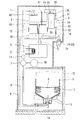
図1に、この発明の実施形態のウォーターサーバーを示す。このウォーターサーバーは、筐体1と、筐体1の内部に配置された冷水タンク2および温水タンク3と、交換式の原水容器4が載置される容器ホルダ5と、容器ホルダ5に載置した原水容器4と冷水タンク2との間を連通する原水供給路6と、原水供給路6に設けられたポンプ7と、原水容器4内に空気を導入する吸気路8と、吸気路8に接続されたオゾン発生装置9とを有する。
FIG. 1 shows a water server according to an embodiment of the present invention. The water server includes a
原水容器4は、水出口10を下向きにした姿勢で容器ホルダ5に載置される。原水容器4の胴部11は、残水量の減少に伴って原水容器4が収縮するように柔軟に形成されている。このような原水容器4は、例えばポリエチレンテレフタレート(PET)樹脂やポリエチレン(PE)樹脂のブロー成形によって形成することができる。原水容器4の容量は、満水状態で8〜20リットル程度である。
The
容器ホルダ5は、原水容器4の交換作業をしやすくするために、筐体1で水平にスライド可能に支持されたスライド台12に取り付けられ、筐体1から出し入れ可能となっている。容器ホルダ5には、原水容器4を容器ホルダ5に載置したときに原水容器4の水出口10に着脱自在に接続されるジョイント部材13が設けられている。ジョイント部材13は、上下方向に延びる中空筒状に形成されている。ジョイント部材13の下端には、原水供給路6の原水容器4側の端部と、吸気路8の原水容器4側の端部とが接続されている。
The
原水供給路6の途中には、ポンプ7と流量センサ14が組み付けられている。ポンプ7は、互いに噛み合う1対の歯車を回転させて飲料水を送り出す歯車ポンプである。ポンプ7を作動させると、原水供給路6内の飲料水が原水容器4側から冷水タンク2側に移送され、原水容器4の飲料水が冷水タンク2に供給されるようになっている。また、ポンプ7は、原水供給路6内の飲料水が無くなったときは、原水供給路6内の空気(オゾン含有空気を含む)を原水容器4側から冷水タンク2側に移送する。流量センサ14は、ポンプ7が作動しているときに原水供給路6内の飲料水が無くなると、その状態を検知可能となっている。
A
冷水タンク2には、冷水タンク2内の飲料水を冷却する冷却装置15が取り付けられている。また、冷水タンク2内には、冷水タンク2の内部を上下に仕切るバッフル板16が設けられている。冷却装置15は、冷水タンク2の下部外周に配置され、冷水タンク2内のバッフル板16よりも下方の飲料水を低温(5℃程度)に保つようになっている。
A
冷水タンク2には、冷水タンク2内に溜まった飲料水の水位を検知する水位センサ17が取り付けられている。この水位センサ17で検知される水位が下がると、その水位の低下に応じてポンプ7が作動し、原水容器4から冷水タンク2に飲料水が供給される。バッフル板16は、原水容器4から冷水タンク2に飲料水が供給されるときに、冷却装置15で冷却されて冷水タンク2の下部に溜まった低温の飲料水が、原水容器4から冷水タンク2内に供給される常温の飲料水で攪拌されるのを防止する。
A
冷水タンク2には、冷水タンク2内の下部に溜まった低温の飲料水を外部に注出する冷水注出路18が接続されている。冷水注出路18には、筐体1の外部から操作可能な冷水コック19が設けられ、この冷水コック19を開くことによって冷水タンク2から低温の飲料水をカップ等に注出できるようになっている。冷水タンク2の容量は、原水容器4の容量よりも小さく、2〜4リットル程度である。
The
バッフル板16の中央には、冷水タンク2と温水タンク3を接続するタンク接続路20の上端が開口している。温水タンク3には、温水タンク3内の飲料水を加熱する加熱装置21が取り付けられており、温水タンク3内の飲料水を高温(90℃程度)に保つようになっている。タンク接続路20の下端は、温水タンク3内の加熱装置21よりも下方の位置で開口している。
At the center of the
温水タンク3には、温水タンク3内の上部に溜まった高温の飲料水を外部に注出する温水注出路22が接続されている。温水注出路22には、筐体1の外部から操作可能な温水コック23が設けられ、この温水コック23を開くことによって温水タンク3から高温の飲料水をカップ等に注出できるようになっている。温水タンク3から飲料水を注出すると、その飲料水と同量の飲料水が、タンク接続路20を通って冷水タンク2から温水タンク3に流入するので、温水タンク3は常に満水状態に保たれる。温水タンク3の容量は1〜2リットル程度である。
Connected to the
冷水タンク2には、空気導入路24を介して空気殺菌チャンバ25が接続されている。空気殺菌チャンバ25は、空気取り入れ口26が形成された中空のケース28と、ケース28内に設けられたオゾン発生体29とからなる。オゾン発生体29としては、例えば、空気中の酸素に紫外線を照射して酸素をオゾンに変化させる低圧水銀灯や、絶縁体で覆われた対向一対の電極間に交流電圧を負荷して電極間の酸素をオゾンに変化させる無声放電装置などを使用することができる。
An
空気導入路24は、冷水タンク2内の水位の低下に応じて冷水タンク2内に空気を導入して冷水タンク2内を大気圧に保つ。また、このとき冷水タンク2内に導入される空気は、空気殺菌チャンバ25内でオゾン殺菌された空気なので、冷水タンク2内の空気を清浄に保つことができる。
The
冷水タンク2内には、原水供給路6から流出した飲料水が、冷水タンク2内に溜まった飲料水の水面に到達するまでの飲料水の流れを拡散させる拡散板30が設けられている。この拡散板30を設けることによって、原水供給路6から流出した飲料水が、冷水タンク2内の空気中のオゾン(空気殺菌チャンバ25から冷水タンク2内に流入したもの)と広い面積で触れるようにし、冷水タンク2内に流入する飲料水の衛生を高めている。
In the
空気導入路24は、途中で分岐してオゾン発生装置9に接続されている。オゾン発生装置9は、入口31と出口32を有する中空のケース33と、そのケース33内に設けられたオゾン発生体34とからなる。ケース33の入口31は空気導入路24に接続され、ケース33の出口32は吸気路8に接続されている。オゾン発生体34は、空気殺菌チャンバ25のオゾン発生体29と同様、空気中の酸素に紫外線を照射して酸素をオゾンに変化させる低圧水銀灯や、絶縁体で覆われた対向一対の電極間に交流電圧を負荷して電極間の酸素をオゾンに変化させる無声放電装置などを使用することができる。
The
原水供給路6と吸気路8は、容器ホルダ5を支持するスライド台12のスライド操作を可能とし、かつ、オゾン発生装置9で発生したオゾンの通過を可能とするため、柔軟性および耐オゾン性をもつ材質で形成されている。このような原水供給路6と吸気路8としては、例えば、シリコンチューブ、フッ素樹脂チューブ、フッ素ゴムチューブを使用することができる。
The raw
ポンプ7とオゾン発生装置9は、図5に示す制御部35によって制御される。制御部35には、水位センサ17から冷水タンク2内に溜まった飲料水の水位を示す信号、流量センサ14から原水供給路6内の飲料水の流量を示す信号が入力される。また、制御部35からは、ポンプ7を駆動する電動モータ36の制御信号、オゾン発生装置9の制御信号、容器交換ランプ37の制御信号が出力される。容器交換ランプ37は、原水容器4が空になったことをユーザーに報知するランプであり、筐体1の正面に配置される。
The
以下、この制御装置35の制御を、図6および図2〜図4に基づいて説明する。
Hereinafter, the control of the
まず、ポンプ7が停止した状態で(ステップS1)、冷水タンク2内の水位があらかじめ設定された下限水位を下回ったことを水位センサ17で検出したときは(ステップS2)、ポンプ7を作動させて、原水容器4の飲料水を冷水タンク2に供給する(ステップS3)。このとき、ポンプ7の作動に連動して、オゾン発生装置9でオゾンを発生させる(ステップS3)。
First, when the
次に、ポンプ7が作動した状態で(ステップS1)、冷水タンク2内の水位があらかじめ設定された上限水位を上回ったことを水位センサ17で検出したときは(ステップS4)、ポンプ7を停止させる(ステップS5)。このとき、ポンプ7の作動に連動して、オゾン発生装置9も停止させる(ステップS5)。ここで、オゾン発生装置9の停止のタイミングは、ポンプ7の停止のタイミングと同時に設定してもよく、ポンプ7が停止してから所定時間が経過した後にオゾン発生装置9が停止するよう設定してもよい。
Next, when the
原水容器4の飲料水を冷水タンク2に供給する上記動作において、図2に示すように、原水容器4内の残水量が多い段階では、ポンプ7が作動して原水容器4の飲料水を汲み出すに伴い、原水容器4が大気圧によって収縮する。そのため、吸気路8から原水容器4内への空気の流入は生じない。
In the above operation for supplying the drinking water from the
一方、図3に示すように、原水容器4内の残水量が少なくなった段階では、原水容器4の収縮が進んで剛性を生じ、それ以上の収縮を生じにくくなっているので、ポンプ7が作動して原水容器4の飲料水を汲み出すときに、原水容器4内の減圧によって吸気路8から原水容器4内に空気が流入する。このとき、オゾン発生装置9でオゾンが発生しているので、そのオゾンが吸気路8とジョイント部材13を順に通過して原水容器4内に流入し、吸気路8の内部およびジョイント部材13の内部がオゾン殺菌される。
On the other hand, as shown in FIG. 3, at the stage where the amount of remaining water in the
図6に示すように、ポンプ7が作動した状態で(ステップS1)、原水供給路6内の飲料水が無くなったことを流量センサ14で検知したときは(ステップS6)、原水容器4の飲料水が無くなったものと考えられるので、容器交換ランプ37を点灯させる(ステップS7)。また、このとき、原水供給路6内の飲料水が無くなったことを流量センサ14で検知した時点から、所定時間が経過するまでポンプ7とオゾン発生装置9を継続して作動させる(ステップS8)。
As shown in FIG. 6, when the
このとき、図4に示すように、オゾン発生装置9で発生したオゾンは、吸気路8とジョイント部材13を順に通って原水容器4の下部に入り、更に、原水容器4の下部からジョイント部材13、原水供給路6を順に通って冷水タンク2内に流入する。これにより、吸気路8の内部、ジョイント部材13の内部、原水供給路6の内部がオゾン殺菌される。
At this time, as shown in FIG. 4, the ozone generated by the
以上のように、このウォーターサーバーを使用すると、ポンプ7の作動に伴って吸気路8から原水容器4内に空気が流入するときに、オゾン発生装置9で発生したオゾンが吸気路8を流れるので、吸気路8の内部がオゾン殺菌され、衛生的である。
As described above, when this water server is used, ozone generated in the
また、このウォーターサーバーを使用すると、交換式の原水容器4の飲料水を使い切るごとに、オゾン発生装置9で発生したオゾンが吸気路8および原水供給路6を通過し、吸気路8と原水供給路6の内部がオゾン殺菌される。そのため、長期にわたってウォーターサーバーを使用したときに、吸気路8と原水供給路6の両方の流路の衛生を保つことが可能である。
When this water server is used, every time the drinking water in the replaceable
上記実施形態では、残水量の減少に伴って収縮する原水容器4を使用した例に挙げて説明したが、この発明は、図7に示すように、残水量が減少しても収縮しない原水容器4を使用するウォーターサーバーにも適用することができる。ここで、原水容器4の胴部11は、原水容器4の残水量が減少しても原水容器4が収縮しないように剛性をもって形成されている。この場合、原水容器4内の残水量の多少にかかわらず、ポンプ7が作動して原水容器4の飲料水を汲み出すときに、原水容器4内の減圧によって吸気路8から原水容器4内に空気が流入する。このとき、オゾン発生装置9でオゾンが発生しているので、そのオゾンが吸気路8とジョイント部材13を順に通過して原水容器4内に流入し、吸気路8の内部およびジョイント部材13の内部をオゾン殺菌することができる。このような剛性をもつ原水容器4は、例えばポリエチレンテレフタレート(PET)樹脂やポリカーボネート(PC)樹脂のブロー成形によって形成することができる。
In the above-described embodiment, the
ところで、オゾン発生装置9で発生したオゾンは時間の経過とともに自然に分解し、酸素に変化する。そのため、原水供給路6と吸気路8の内部をオゾン殺菌するときに、オゾン発生装置9で発生したオゾンが原水供給路6に到達するまでに要する時間が長いと、オゾン濃度が低下し、原水供給路6の殺菌効果が弱まる可能性がある。
By the way, ozone generated by the
そこで、図8に示すように、原水供給路6と吸気路8をジョイント部材13の内部で互いに連通させることができる。このようにすると、吸気路8を通ってジョイント部材13に入ったオゾンが、原水容器4を介さずに原水供給路6に流入するので、オゾン発生装置9で発生したオゾンが原水供給路6に到達するまでに要する時間を短くすることができ、原水供給路6をより効果的に殺菌することが可能となる。
Therefore, as shown in FIG. 8, the raw
また、図9に示すように、原水供給路6と吸気路8をジョイント部材13の内部で互いに連通させる場合、ジョイント部材13の内部に設けた上下方向に延びる隔壁38を介して原水供給路6と吸気路8を仕切り、その隔壁38の上方で原水供給路6と吸気路8を連通させることができる。このようにしても、吸気路8を通ってジョイント部材13に入ったオゾンが、原水容器4を介さずに原水供給路6に流入するので、オゾン発生装置9で発生したオゾンが原水供給路6に到達するまでに要する時間を短くすることができ、原水供給路6を効果的に殺菌することが可能となる。さらに、原水容器4から原水供給路6に飲料水が流出すると同時に吸気路8から原水容器4内に空気が流入するときに、ジョイント部材13の内部で吸気路8から原水供給路6に空気が吸い込まれるのを防止することができ、ポンプ7による飲料水の汲み上げが円滑となる。
Further, as shown in FIG. 9, when the raw
また、図10、図11に示すような切替バルブ39を原水容器4の近傍に設けることができる。この切替バルブ39は、ポンプ7と原水容器4の間が原水供給路6を介して連通され、かつ、オゾン発生装置9と原水容器4の間が吸気路8を介して連通された連通状態(図10参照)と、ポンプ7と原水容器4の間の原水供給路6の連通が遮断され、かつ、オゾン発生装置9と原水容器4の間の吸気路8の連通が遮断された遮断状態(図11参照)との間で流路を切り替えるとともに、その切替バルブ39で前記遮断状態に切り替えた状態において、原水供給路6の切替バルブ39よりもポンプ7側の部位と、吸気路8の切替バルブ39よりもオゾン発生装置9側の部位とを互いに連通させるように構成されている。このようにすると、切替バルブ39を前記遮断状態に切り替えた状態において、ポンプ7を作動させるとともにオゾン発生装置9でオゾンを発生させることにより、原水容器4内に飲料水が入った状態でも、吸気路8および原水供給路6をオゾン殺菌することが可能となる。図10、図11では、切替バルブ39を単一のバルブで構成した例を示しているが、複数の開閉弁を組み合わせて同一の作用をもつ切替バルブ39を構成してもよい。
Further, a switching
図1に示す構成のウォーターサーバーにおいて、オゾン発生装置9で発生したオゾンが吸気路8を通過するときに、どの程度の減衰率をもってオゾン濃度が減衰するかを測定する実験を行なった。実験の条件は次のとおりである。
吸気路 :シリコンチューブ
吸気路の内径:4mm
ポンプ送気量:1000cc/min
オゾン発生体:石英管放電灯(シングルランプ、ダブルランプ)
In the water server having the configuration shown in FIG. 1, an experiment was conducted to measure how much the ozone concentration attenuates when ozone generated by the
Intake channel: Silicon tube Inner diameter of intake channel: 4mm
Pump air supply: 1000cc / min
Ozone generator: quartz tube discharge lamp (single lamp, double lamp)
この実験の結果、オゾン発生体34として石英管放電灯(シングルランプ)を使用したときは、オゾン濃度が次のように減衰することを確認した。結果を表1に示す。
As a result of this experiment, when a quartz tube discharge lamp (single lamp) was used as the

またオゾン発生体34として石英管放電灯(ダブルランプ)を使用したときは、オゾン濃度が次のように減衰することを確認した。結果を表2に示す。
When a quartz tube discharge lamp (double lamp) was used as the
これらの測定結果を見ると、シングルランプでオゾンを発生するよりも、ダブルランプでオゾンを発生したときの方が、オゾンの減衰率が小さい。このことから、オゾン発生装置9で発生するオゾン濃度が高いほど、オゾンの減衰率が小さくなることが分かる。そして、オゾン発生装置9から5.5ppm前後のオゾン含有空気を吸気路8に流入させれば、3m以内の長さをもつ吸気路8を効果的にオゾン殺菌することができることを確認した。
Looking at these measurement results, the ozone decay rate is smaller when ozone is generated with a double lamp than when ozone is generated with a single lamp. From this, it can be seen that the higher the concentration of ozone generated by the
2 冷水タンク
4 原水容器
6 原水供給路
7 ポンプ
8 吸気路
9 オゾン発生装置
35 制御部
2
Claims (1)
前記制御部(35)は、前記原水容器(4)内に飲料水が無くなったときに、前記ポンプ(7)を継続して作動させることで前記吸気路(8)および原水供給路(6)内にオゾンを通過させる制御を行なうウォーターサーバー。 A cold water tank (2) for cooling drinking water, a raw water supply path (6) communicating between the replaceable raw water container (4) and the cold water tank (2), and the raw water supply path (6) are provided. A pump (7), an intake passage (8) for introducing air into the raw water container (4), an ozone generator (9) connected to the intake passage (8), and the pump (7) control unit for performing the control for generating ozone in an ozone generator (9) during operation and (35) possess,
The controller (35) continuously operates the pump (7) when the drinking water is exhausted in the raw water container (4), thereby allowing the intake passage (8) and the raw water supply passage (6). Water server that controls ozone to pass through.
Priority Applications (7)
| Application Number | Priority Date | Filing Date | Title |
|---|---|---|---|
| JP2012046302A JP5647636B2 (en) | 2012-03-02 | 2012-03-02 | Water server |
| TW101115641A TW201336770A (en) | 2012-03-02 | 2012-05-02 | Water server |
| PCT/JP2012/067073 WO2013128665A1 (en) | 2012-03-02 | 2012-07-04 | Water server |
| EP12869947.7A EP2821365A4 (en) | 2012-03-02 | 2012-07-04 | Water server |
| CN201280070984.XA CN104136363B (en) | 2012-03-02 | 2012-07-04 | Water dispenser |
| KR20147025245A KR20140130468A (en) | 2012-03-02 | 2012-07-04 | Water server |
| US14/380,974 US20150151957A1 (en) | 2012-03-02 | 2012-07-04 | Water server |
Applications Claiming Priority (1)
| Application Number | Priority Date | Filing Date | Title |
|---|---|---|---|
| JP2012046302A JP5647636B2 (en) | 2012-03-02 | 2012-03-02 | Water server |
Publications (3)
| Publication Number | Publication Date |
|---|---|
| JP2013180808A JP2013180808A (en) | 2013-09-12 |
| JP2013180808A5 JP2013180808A5 (en) | 2014-11-20 |
| JP5647636B2 true JP5647636B2 (en) | 2015-01-07 |
Family
ID=49081901
Family Applications (1)
| Application Number | Title | Priority Date | Filing Date |
|---|---|---|---|
| JP2012046302A Active JP5647636B2 (en) | 2012-03-02 | 2012-03-02 | Water server |
Country Status (7)
| Country | Link |
|---|---|
| US (1) | US20150151957A1 (en) |
| EP (1) | EP2821365A4 (en) |
| JP (1) | JP5647636B2 (en) |
| KR (1) | KR20140130468A (en) |
| CN (1) | CN104136363B (en) |
| TW (1) | TW201336770A (en) |
| WO (1) | WO2013128665A1 (en) |
Families Citing this family (6)
| Publication number | Priority date | Publication date | Assignee | Title |
|---|---|---|---|---|
| JP5583296B1 (en) * | 2014-04-15 | 2014-09-03 | 株式会社コスモライフ | Water server |
| CN106335865B (en) * | 2016-08-25 | 2018-11-02 | 胡惜忠 | The connection structure of a kind of water level probe and bottle and the beverage bottle using the structure |
| JP6309662B1 (en) * | 2017-02-21 | 2018-04-11 | 株式会社 浜松ベジタブル | Beverage supply equipment |
| JP6324559B1 (en) * | 2017-02-21 | 2018-05-16 | 株式会社 浜松ベジタブル | Beverage supply equipment |
| CN111683894A (en) * | 2017-12-28 | 2020-09-18 | 三得利控股株式会社 | Water dispenser and water supply method for water dispenser |
| WO2023196488A2 (en) * | 2022-04-07 | 2023-10-12 | Quench Usa, Inc. | Cleaning modes for water dispenser |
Family Cites Families (20)
| Publication number | Priority date | Publication date | Assignee | Title |
|---|---|---|---|---|
| US3333438A (en) * | 1965-01-05 | 1967-08-01 | Ebco Mfg Company | Water cooler and dispenser having a replaceable reservoir |
| US3726404A (en) * | 1971-07-26 | 1973-04-10 | Moody Aquamatics Syst Inc | Batch ozonators for drinking water |
| US5366619A (en) * | 1993-10-13 | 1994-11-22 | Suntory Limited | Germfree drinking water dispenser |
| US5451314A (en) * | 1994-04-09 | 1995-09-19 | Neuenschwander; Peter | Plant for the treatment of drinking water from raw water |
| US6090281A (en) * | 1998-08-06 | 2000-07-18 | Buckner; Lynn | Beverage storage and dispensing container |
| JP2000085893A (en) * | 1998-09-17 | 2000-03-28 | Fuji Electric Co Ltd | Potable water dispenser |
| US6561382B2 (en) * | 2001-06-15 | 2003-05-13 | S.I.P. Technologies, L.L.C. | Method and apparatus for disinfecting a water cooler reservoir and its dispensing spigot(s) |
| US7175054B2 (en) * | 1998-12-23 | 2007-02-13 | S.I.P. Technologies, Llc | Method and apparatus for disinfecting a refrigerated water cooler reservoir |
| US6237245B1 (en) * | 1999-07-01 | 2001-05-29 | Lee Valley Tools, Ltd. | Microwave flower press |
| JP2001153523A (en) * | 1999-11-19 | 2001-06-08 | Kyushu Kaihatsu Kikaku:Kk | Drink water heater and drink water cooler and drink water heater/cooler |
| US6684648B2 (en) * | 2000-07-26 | 2004-02-03 | Fakieh Research & Development Center | Apparatus for the production of freshwater from extremely hot and humid air |
| US6732885B2 (en) * | 2002-08-27 | 2004-05-11 | Hymore, Inc. | Beverage supply system |
| US7422684B1 (en) * | 2003-10-16 | 2008-09-09 | S.I.P. Technologies, L.L.C. | Method and apparatus for sanitizing water dispensed from a water dispenser having a reservoir |
| JP2006341915A (en) * | 2005-06-10 | 2006-12-21 | Ohnit Co Ltd | Potable water dispenser |
| US8177096B2 (en) * | 2007-03-27 | 2012-05-15 | International Packaging Innovations, Llc | Bag cooler employing a multi-spike adapter and converter |
| JP4317262B1 (en) * | 2009-03-30 | 2009-08-19 | 株式会社コスモライフ | Beverage dispenser |
| US20100252570A1 (en) * | 2009-04-01 | 2010-10-07 | Yui George M | Bottom loading water cooler |
| US8356731B2 (en) * | 2009-09-09 | 2013-01-22 | Mtn Products Inc | Energy saving baffle for water cooler |
| JP4802299B1 (en) | 2011-04-12 | 2011-10-26 | 株式会社オーケンウォーター | Water server for easy replacement of water bottles |
| JP5487164B2 (en) * | 2011-07-08 | 2014-05-07 | 株式会社コスモライフ | Water server and air sterilization chamber for water server |
-
2012
- 2012-03-02 JP JP2012046302A patent/JP5647636B2/en active Active
- 2012-05-02 TW TW101115641A patent/TW201336770A/en unknown
- 2012-07-04 US US14/380,974 patent/US20150151957A1/en not_active Abandoned
- 2012-07-04 EP EP12869947.7A patent/EP2821365A4/en not_active Withdrawn
- 2012-07-04 WO PCT/JP2012/067073 patent/WO2013128665A1/en active Application Filing
- 2012-07-04 CN CN201280070984.XA patent/CN104136363B/en not_active Expired - Fee Related
- 2012-07-04 KR KR20147025245A patent/KR20140130468A/en not_active Application Discontinuation
Also Published As
| Publication number | Publication date |
|---|---|
| TW201336770A (en) | 2013-09-16 |
| KR20140130468A (en) | 2014-11-10 |
| CN104136363B (en) | 2016-08-10 |
| EP2821365A4 (en) | 2016-03-09 |
| US20150151957A1 (en) | 2015-06-04 |
| EP2821365A1 (en) | 2015-01-07 |
| CN104136363A (en) | 2014-11-05 |
| JP2013180808A (en) | 2013-09-12 |
| WO2013128665A1 (en) | 2013-09-06 |
Similar Documents
| Publication | Publication Date | Title |
|---|---|---|
| JP5647636B2 (en) | Water server | |
| JP5529314B1 (en) | Water server | |
| CN105189334B (en) | Water server | |
| KR102092434B1 (en) | Water dispenser | |
| JP5529312B1 (en) | Water server | |
| JP5487164B2 (en) | Water server and air sterilization chamber for water server | |
| TW201400398A (en) | Water server | |
| JP5529201B2 (en) | Water server | |
| JP5571218B1 (en) | Water server | |
| WO2014136346A1 (en) | Water dispenser | |
| JP2018119352A (en) | Drinking water generating device | |
| JP5806433B2 (en) | Water server | |
| JP5806432B2 (en) | Water server |
Legal Events
| Date | Code | Title | Description |
|---|---|---|---|
| A521 | Request for written amendment filed |
Free format text: JAPANESE INTERMEDIATE CODE: A523 Effective date: 20141006 |
|
| A621 | Written request for application examination |
Free format text: JAPANESE INTERMEDIATE CODE: A621 Effective date: 20141006 |
|
| A871 | Explanation of circumstances concerning accelerated examination |
Free format text: JAPANESE INTERMEDIATE CODE: A871 Effective date: 20141006 |
|
| RD03 | Notification of appointment of power of attorney |
Free format text: JAPANESE INTERMEDIATE CODE: A7423 Effective date: 20141006 |
|
| TRDD | Decision of grant or rejection written | ||
| A975 | Report on accelerated examination |
Free format text: JAPANESE INTERMEDIATE CODE: A971005 Effective date: 20141016 |
|
| A01 | Written decision to grant a patent or to grant a registration (utility model) |
Free format text: JAPANESE INTERMEDIATE CODE: A01 Effective date: 20141021 |
|
| A61 | First payment of annual fees (during grant procedure) |
Free format text: JAPANESE INTERMEDIATE CODE: A61 Effective date: 20141107 |
|
| R150 | Certificate of patent or registration of utility model |
Ref document number: 5647636 Country of ref document: JP Free format text: JAPANESE INTERMEDIATE CODE: R150 |
|
| S111 | Request for change of ownership or part of ownership |
Free format text: JAPANESE INTERMEDIATE CODE: R313111 |
|
| R350 | Written notification of registration of transfer |
Free format text: JAPANESE INTERMEDIATE CODE: R350 |
|
| R250 | Receipt of annual fees |
Free format text: JAPANESE INTERMEDIATE CODE: R250 |
|
| R250 | Receipt of annual fees |
Free format text: JAPANESE INTERMEDIATE CODE: R250 |
|
| R250 | Receipt of annual fees |
Free format text: JAPANESE INTERMEDIATE CODE: R250 |
|
| R250 | Receipt of annual fees |
Free format text: JAPANESE INTERMEDIATE CODE: R250 |
|
| R250 | Receipt of annual fees |
Free format text: JAPANESE INTERMEDIATE CODE: R250 |
|
| R250 | Receipt of annual fees |
Free format text: JAPANESE INTERMEDIATE CODE: R250 |
|
| R250 | Receipt of annual fees |
Free format text: JAPANESE INTERMEDIATE CODE: R250 |