JP5642481B2 - Loading platform lifting device - Google Patents

Loading platform lifting device Download PDF

Info

Publication number
JP5642481B2
JP5642481B2 JP2010218831A JP2010218831A JP5642481B2 JP 5642481 B2 JP5642481 B2 JP 5642481B2 JP 2010218831 A JP2010218831 A JP 2010218831A JP 2010218831 A JP2010218831 A JP 2010218831A JP 5642481 B2 JP5642481 B2 JP 5642481B2
Authority
JP
Japan
Prior art keywords
load receiving
receiving table
drive device
lift
tilt
Prior art date
Legal status (The legal status is an assumption and is not a legal conclusion. Google has not performed a legal analysis and makes no representation as to the accuracy of the status listed.)
Active
Application number
JP2010218831A
Other languages
Japanese (ja)
Other versions
JP2012071730A5 (en
JP2012071730A (en
Inventor
古川 威
威 古川
Current Assignee (The listed assignees may be inaccurate. Google has not performed a legal analysis and makes no representation or warranty as to the accuracy of the list.)
Shinmaywa Industries Ltd
Original Assignee
Shinmaywa Industries Ltd
Priority date (The priority date is an assumption and is not a legal conclusion. Google has not performed a legal analysis and makes no representation as to the accuracy of the date listed.)
Filing date
Publication date
Application filed by Shinmaywa Industries Ltd filed Critical Shinmaywa Industries Ltd
Priority to JP2010218831A priority Critical patent/JP5642481B2/en
Publication of JP2012071730A publication Critical patent/JP2012071730A/en
Publication of JP2012071730A5 publication Critical patent/JP2012071730A5/ja
Application granted granted Critical
Publication of JP5642481B2 publication Critical patent/JP5642481B2/en
Active legal-status Critical Current
Anticipated expiration legal-status Critical

Links

Images

Description

本発明は車両の荷台に対する荷物の積み降ろし作業を支援する荷受台昇降装置に関する。   The present invention relates to a loading platform lifting / lowering device that supports loading and unloading work of a load on a loading platform of a vehicle.

荷受台昇降装置とは、車両の荷台入口付近で荷受台を昇降させ、車両の荷台に対する荷物や作業者の積み降ろし作業を支援するものである。このうち、車両に取り付けた基部にアームを介して荷受台を連結し、基部に対してアームを上下方向に回動させて荷受台を昇降させるものがある(特許文献1等参照)。同文献の荷受台昇降装置は、格納姿勢に移行させるべくアームを上昇させる際、予め荷受台をガイドローラに立て掛けておき、荷受台の動きをガイドローラでガイドしている。   The load receiving platform lifting / lowering device lifts and lowers the load receiving platform in the vicinity of the vehicle loading platform entrance, and supports loading and unloading work of luggage and workers on the loading platform of the vehicle. Among these, there is a type in which a load receiving platform is connected to a base attached to a vehicle via an arm, and the load receiving platform is moved up and down by rotating the arm up and down with respect to the base (see Patent Document 1 and the like). When lifting the arm to shift to the retracted posture, the load receiving platform lifting apparatus of the same document is preliminarily leaned against the guide roller, and the movement of the load receiving table is guided by the guide roller.

特開2005−138741号公報JP-A-2005-138741

例えば特許文献1の荷受台昇降装置では、前述した通り、荷受台の格納の際、アームを駆動する前に人手で荷受台を起こしてガイドローラに立て掛ける必要がある。また、荷受台の展開の際にも、ガイドローラに凭れた状態の荷受台を広げて水平な状態にする作業を人手で行わなければならない。   For example, in the load receiving table lifting device of Patent Document 1, as described above, when storing the load receiving table, it is necessary to manually raise the load receiving table and lean it against the guide roller before driving the arm. In addition, when unloading the load receiving table, it is necessary to manually perform the work of expanding the load receiving table in a state where it is trapped by the guide rollers to make it horizontal.

そこで、荷受台を傾動させる駆動装置を設けて、こうした人手作業の煩わしさを軽減することが考えられる。この場合、例えば展開動作時にはアームを下に回動させて荷受台を接地させた後、荷受台を水平姿勢に向けて傾動させることになるが、作業者の使い勝手を考慮すれば、ボタン1つでアームの下降動作と荷受台の傾動動作とが自動的に連続して実行されるようにすることが望ましい。格納動作も同様である。   In view of this, it is conceivable to provide a drive device for tilting the load receiving table to reduce the troublesome manual work. In this case, for example, at the time of unfolding operation, the arm is turned downward to ground the load receiving table, and then the load receiving table is tilted toward the horizontal posture. However, considering the convenience of the operator, one button is required. Therefore, it is desirable that the lowering operation of the arm and the tilting operation of the load receiving table are performed automatically and continuously. The storage operation is the same.

例えば展開動作時を考えると、荷受台の下降動作と傾動動作を自動で連続して実行させるには、下降動作から傾動動作に移行させるトリガとして荷受台が接地したことを荷受台昇降装置が認識する必要がある。この場合、荷受台が最初に接地する部分に何らかのセンサを取り付け、荷受台が接地したことをセンサで検出する構成とすることが考えられる。他方、格納動作時においても、荷受台の傾動動作から上昇動作に移行するトリガとして、荷受台がガイドローラに接触したことを認識する必要があり、例えば荷受台がガイドローラに立て掛かったことを検出するセンサをガイドローラの近傍に設置することが考えられる。   For example, when the unloading operation is considered, in order to automatically and continuously execute the descending and tilting operations of the loading platform, the loading platform lifting device recognizes that the loading platform has been grounded as a trigger for shifting from the descending motion to the tilting motion. There is a need to. In this case, it is conceivable that some sensor is attached to the part where the cargo receiving platform first contacts the ground, and the sensor detects that the cargo receiving platform is grounded. On the other hand, even during the storing operation, it is necessary to recognize that the load receiving table has contacted the guide roller as a trigger for shifting from the tilting operation of the load receiving table to the ascending operation, for example, that the load receiving table has stood against the guide roller. It is conceivable to install a sensor to be detected in the vicinity of the guide roller.

しかしながら、地面又はガイドローラに荷受台が実際に接触するよりも、僅かに早くセンサが反応してしまう場合がある。例えばセンサとして音波や光、磁力等で荷受台と地面等との距離を検出する非接触式の近接センサを用いた場合、実際に荷受台が地面等に接触する前に荷受台と地面等とが近接した時点で接触を検出してしまい得る。また、リミットスイッチのように外力を受けて接触を検知する機械式のセンサであっても、厳密に見れば、荷受台が地面等と接触するよりも僅かに早くセンサが地面等に接触することになるため、実際に地面等に荷受台が接触するよりも僅かに早くセンサが反応し得る。   However, the sensor may react slightly faster than the cargo cradle actually contacts the ground or the guide roller. For example, when a non-contact type proximity sensor that detects the distance between the load receiving platform and the ground or the like using sound waves, light, magnetic force, or the like is used as the sensor, the load receiving platform and the ground or the like before the load receiving platform actually contacts the ground or the like. The contact may be detected at the time of close proximity. Moreover, even if it is a mechanical sensor that detects contact by receiving external force, such as a limit switch, if it is strictly observed, the sensor contacts the ground etc. slightly earlier than the load receiving table contacts the ground etc. Therefore, the sensor can react slightly faster than the load receiving table actually contacts the ground or the like.

このように意図するタイミングよりもセンサが早く反応してしまうと、展開動作時に接地動作が確実に行われるより若干早く荷受台が傾動し始める、又は格納動作時に確実にガイドローラに接触するより若干早く荷受台が上昇し始める等の挙動が生じ得るし、急な動作切り換えによる異音発生の要因ともなり得る。これらの現象が実用上の問題につながる可能性は高くないが、装置を使用する作業者に心理的負担を与えかねない。こうした心理的負担を軽減する上でも、ユーザーフレンドリーの見地から格納動作及び展開動作が一操作で実行されるようにするに際して荷受台昇降装置の動作の高い信頼性を確保する必要がある。そして、この点は他の荷受台昇降装置を展開動作及び格納動作を自動化する場合にも言えることであり、荷受台の格納及び展開の過程で荷受台の傾動と昇降の動作を連続させる必要がある構成において同様に内在する課題である。   If the sensor reacts earlier than the intended timing in this way, the load receiving platform starts to tilt slightly earlier than when the grounding operation is surely performed during the unfolding operation, or slightly more than when it reliably contacts the guide roller during the storage operation. A behavior such as the cargo cradle starting to rise quickly can occur, and it can also be a cause of abnormal noise due to sudden operation switching. Although these phenomena are not likely to lead to practical problems, they may put a psychological burden on workers who use the apparatus. In order to reduce such a psychological burden, it is necessary to ensure high reliability of the operation of the load receiving platform lifting / lowering device when the storing operation and the unfolding operation are executed by one operation from a user-friendly viewpoint. This point can also be said when another unloading device lifting / lowering apparatus is automated in its unfolding operation and retracting operation, and it is necessary to continue the tilting and lifting operations of the unloading table in the process of storing and unfolding the load receiving table. This is an inherent problem in a certain configuration.

本発明は上記の事情に鑑みなされたもので、荷受台の傾動を含めた一連の格納動作又は展開動作を自動化して作業者の負担を軽減しつつ、一連の動作の高い信頼性を確保して作業者の心理的負担を軽減することができる荷受台昇降装置を提供することを目的とする。   The present invention has been made in view of the above circumstances, and ensures a high reliability of a series of operations while reducing a burden on an operator by automating a series of storage operations or deployment operations including tilting of a load receiving platform. It is an object of the present invention to provide a load receiving table lifting / lowering device that can reduce the psychological burden on an operator.

上記目的を達成するために、第1の発明は、車両の荷台に対する荷物の積み降ろしを支援する荷受台昇降装置において、前記車両に取り付けたベースユニットと、このベースユニットに対して上下動可能に連結されたアームユニットと、このアームユニットに対して傾動可能に連結された荷受台と、前記アームユニットを上下動させるリフト駆動装置と、前記荷受台を傾動させる傾動駆動装置と、前記リフト駆動装置及び前記傾動駆動装置を制御する制御装置とを備え、前記制御装置は、展開動作時又は格納動作時に前記荷受台の昇降動作と傾動動作とを続けて実行するに際し、前記リフト駆動装置及び前記傾動駆動装置のいずれか一方の駆動装置の動作中に動作切り換えのトリガとなる検出信号を入力したら、前記一方の駆動装置を動作させつつ設定時間が経過するのを待って、その一方の駆動装置の動作中に他方の駆動装置の動作を指令することを特徴とする。 In order to achieve the above object, according to a first aspect of the present invention, there is provided a load receiving platform lifting / lowering device for supporting loading / unloading of a load on a vehicle loading platform, and a base unit attached to the vehicle and capable of moving up and down relative to the base unit. A coupled arm unit, a load receiving base that is tiltably connected to the arm unit, a lift driving device that moves the arm unit up and down, a tilt driving device that tilts the load receiving base, and the lift driving device And the control device for controlling the tilt drive device, and the control device performs the lifting and tilting operations of the load receiving table during the unfolding operation or the retracting operation in succession. After entering the detection signal as a trigger for operating the switching during operation of one of the drive of the drive device, operation of the one drive unit Waiting for the elapse of the set time while, characterized in that commands operation of the other drive device during operation of the one drive.

第2の発明は、車両の荷台に対する荷物の積み降ろしを支援する荷受台昇降装置において、前記車両に取り付けたベースユニットと、このベースユニットに対して上下動可能に連結されたアームユニットと、このアームユニットに対して傾動可能に連結された荷受台と、この荷受台を格納及び展開する際に当該荷受台をガイドするガイドローラと、前記アームユニットを上下動させるリフト駆動装置と、前記荷受台を傾動させる傾動駆動装置と、傾動駆動装置のボトム側油室とロッド側油室を接続するバイパス管路と、前記アームユニットが上昇位置にないことを検出するアームセンサと、前記荷受台が前記ガイドローラに接していることを検出するローラセンサと、前記荷受台が接地していることを検出する接地センサと、前記リフト駆動装置に対する作動油の流れを制御するリフト用コントロールバルブと、前記傾動駆動装置に対する作動油の流れを制御する傾動用コントロールバルブと、前記バイパス管路に設けた切換弁と、前記リフト用コントロールバルブ、前記傾動用コントロールバルブ及び前記切換弁を制御する制御装置とを備え、展開動作時、前記制御装置は、前記リフト用コントロールバルブ及び前記切換弁に指令信号を出力し、前記リフト駆動装置を縮退動作させるとともに前記バイパス管路を開いて傾動駆動装置をフリーにする手順と、前記アームユニットが前記上昇位置から動いて前記アームセンサからの検出信号が入力されると、前記傾動用コントロールバルブに指令信号を出力して前記傾動駆動装置のボトム側及びロッド側の油室をタンクに接続し、前記ガイドローラに倣わせて前記荷受台を起立させていく手順と、前記荷受台の下降中に前記荷受台が設置して前記接地センサからの検出信号が入力されたら、前記リフト駆動装置の縮退動作を継続させつつ設定時間が経過するのを待って前記傾動用コントロールバルブに指令信号を出力し、前記リフト駆動装置の縮退動作中に前記傾動駆動装置を伸長させて前記荷受台を展開させる手順とを実行することを特徴とする。 According to a second aspect of the present invention, there is provided a load receiving platform lifting / lowering device for supporting loading / unloading of a load on a vehicle loading platform, a base unit attached to the vehicle, an arm unit coupled to the base unit so as to be movable up and down, A load receiving base that is tiltably connected to the arm unit, a guide roller that guides the load receiving base when the load receiving base is stored and deployed, a lift driving device that moves the arm unit up and down, and the load receiving base A tilt drive device that tilts the valve, a bypass pipe that connects the bottom oil chamber and the rod oil chamber of the tilt drive device, an arm sensor that detects that the arm unit is not in the raised position, and the load receiving platform a roller sensor for detecting that the contact with the guide roller, a ground sensor for detecting that the receiving platform is grounded, the lift drive A lift control valve which controls the flow of hydraulic fluid to location, and the tilting control valve for controlling the flow of hydraulic fluid to the tilting drive device, and a switching valve provided in the bypass conduit, the lift control valve, A control device for controlling the tilting control valve and the switching valve, and during the unfolding operation, the control device outputs a command signal to the lifting control valve and the switching valve, and degenerates the lift driving device. And a procedure for opening the bypass conduit to make the tilting drive device free, and a command signal to the tilting control valve when the arm unit is moved from the raised position and a detection signal is input from the arm sensor. To connect the oil chamber on the bottom side and the rod side of the tilt drive unit to the tank, When the procedure by modeled after the guide roller will thereby erecting the receiving platform, the detection signal from the ground sensor the receiving platform during descent of the receiving platform are installed is inputted, restricted operation of the lift driving device A procedure for outputting a command signal to the tilting control valve while waiting for a set time to elapse, and extending the tilting drive device during the retracting operation of the lift drive device to deploy the load receiving table ; It is characterized by performing .

第3の発明は、車両の荷台に対する荷物の積み降ろしを支援する荷受台昇降装置において、前記車両に取り付けたベースユニットと、このベースユニットに対して上下に回動可能に連結されたアームユニットと、このアームユニットに対して傾動可能に連結された荷受台と、この荷受台を格納及び展開する際に当該荷受台をガイドするガイドローラと、前記アームユニットを上下に回動させるリフト駆動装置と、前記荷受台を傾動させる傾動駆動装置と、前記荷受台が前記ガイドローラに接触していることを検出するローラセンサと、前記リフト駆動装置に対する作動油の流れを制御するリフト用コントロールバルブと、前記傾動駆動装置に対する作動油の流れを制御する傾動用コントロールバルブと、前記リフト駆動装置及び前記傾動駆動装置を制御する制御装置とを備え、格納動作時、前記制御装置は、前記傾動用コントロールバルブに指令信号を出力し、前記傾動駆動装置を縮退させて接地した状態で前記荷受台を傾動させて前記ガイドローラに凭せ掛ける手順と、前記荷受台の傾動中に前記荷受台が前記ガイドローラに凭れ掛かって前記ローラセンサからの検出信号が入力されたら、前記傾動駆動装置への作動油の供給を継続しつつ設定時間が経過するのを待って前記リフト用コントロールバルブに指令信号を出力し、前記リフト駆動装置を縮退させて前記荷受台を前記ガイドローラに押し付けながら上昇させて格納する手順とを実行することを特徴とする。 According to a third aspect of the present invention, there is provided a load receiving platform lifting / lowering device for supporting loading / unloading of a load on a vehicle loading platform, a base unit attached to the vehicle, and an arm unit coupled to the base unit so as to be vertically rotatable. A load receiving base that is tiltably connected to the arm unit, a guide roller that guides the load receiving base when the load receiving base is stored and deployed, and a lift drive device that rotates the arm unit up and down. A tilt driving device for tilting the load receiving table, a roller sensor for detecting that the load receiving table is in contact with the guide roller, a lift control valve for controlling a flow of hydraulic oil to the lift driving device, a tilt control valve for controlling the flow of hydraulic fluid to the tilting drive unit, the lift drive unit and the tilt drive And a control device for controlling the location, time of storage operation, the control device, the the tilting control valve outputs a command signal, is tilted the receiving platform while grounded by degenerating the tilting drive device The procedure of leaning on the guide roller, and supply of hydraulic oil to the tilting drive device when the load receiving table leans on the guide roller and the detection signal from the roller sensor is input during tilting of the load receiving table A procedure for outputting a command signal to the lift control valve while waiting for a set time to elapse, retracting the lift driving device and pushing the load receiving table against the guide roller to store It is characterized by performing .

本発明によれば、荷受台の傾動を含めた一連の格納動作又は展開動作を自動化して作業者の負担を軽減しつつ、一連の動作の高い信頼性を確保することができる。   ADVANTAGE OF THE INVENTION According to this invention, high reliability of a series of operation | movement can be ensured, automating a series of storing operation | movement or expansion | deployment operation | movement including inclination of a receiving stand, and reducing a worker's burden.

本発明の第1実施形態に係る荷受台昇降装置を搭載した車両の全体構造を表す側面図であり、展開姿勢、格納姿勢及び中間姿勢の状態の荷受台昇降装置を併せて図示した図である。BRIEF DESCRIPTION OF THE DRAWINGS FIG. 1 is a side view showing an overall structure of a vehicle on which a load receiving platform lifting apparatus according to a first embodiment of the present invention is mounted, and is a view illustrating the load receiving platform lifting apparatus in a deployed posture, a retracted posture and an intermediate posture. . 本発明の第1実施形態に係る荷受台昇降装置の斜視図であり、荷受台が展開姿勢にある状態を表す図である。It is a perspective view of the load receiving table raising / lowering apparatus which concerns on 1st Embodiment of this invention, and is a figure showing the state which has a load receiving stand in a deployment attitude | position. 本発明の第1実施形態に係る荷受台昇降装置の斜視図であり、荷受台が接地してガイドローラに凭れた状態を表す図である。It is a perspective view of the load receiving table raising / lowering device which concerns on 1st Embodiment of this invention, and is a figure showing the state which the load receiving stand grounded and fell in the guide roller. 本発明の第1実施形態に係る荷受台昇降装置の斜視図であり、荷受台が地面から離れてガイドローラに支持されている状態を表す図である。It is a perspective view of the load receiving table raising / lowering apparatus which concerns on 1st Embodiment of this invention, and is a figure showing the state in which the load receiving stand is separated from the ground and is supported by the guide roller. 本発明の第1実施形態に係る荷受台昇降装置の斜視図であり、荷受台が格納姿勢にある状態を表す図である。It is a perspective view of the load receiving table raising / lowering apparatus which concerns on 1st Embodiment of this invention, and is a figure showing the state which has a load receiving stand in a storing attitude | position. 本発明の第1実施形態に係る荷受台昇降装置に備えられた荷受台の斜視図である。It is a perspective view of the load receiving stand with which the load receiving stand raising / lowering device which concerns on 1st Embodiment of this invention was equipped. 本発明の第1実施形態に係る荷受台昇降装置に備えられたロック装置をベースユニットとともに表す側面図である。It is a side view showing the locking device with which the load receiving table raising / lowering device which concerns on 1st Embodiment of this invention was equipped with the base unit. 本発明の第1実施形態に係る荷受台昇降装置に備えられたロック装置をベースユニットとともに表すである。It is a lock | rock apparatus with which the load receiving table raising / lowering apparatus which concerns on 1st Embodiment of this invention was equipped is represented with a base unit. 本発明の第1実施形態に係る荷受台昇降装置に備えられた操作レバーの近傍の構成を表す拡大透視図である。It is an expansion perspective view showing the structure of the vicinity of the operation lever with which the cargo receiving platform raising / lowering apparatus which concerns on 1st Embodiment of this invention was equipped. 本発明の第1実施形態に係る荷受台昇降装置に備えられたリフト駆動装置及び傾動駆動装置の油圧駆動装置の回路図である。It is a circuit diagram of the hydraulic drive device of the lift drive device and tilt drive device provided in the load receiving table lifting device according to the first embodiment of the present invention. 本発明の第1実施形態に係る荷受台昇降装置の制御手段に備えられたリレー回路の回路図である。It is a circuit diagram of the relay circuit with which the control means of the load receiving table raising / lowering apparatus which concerns on 1st Embodiment of this invention was equipped. 本発明の第1実施形態に係る荷受台昇降装置に備えられた制御手段による荷受台の展開動作の制御手順を表す模式図である。It is a schematic diagram showing the control procedure of the unfolding operation | movement of the load receiving stand by the control means with which the load receiving stand raising / lowering apparatus which concerns on 1st Embodiment of this invention was equipped. 本発明の第1実施形態に係る荷受台昇降装置に備えられた制御手段による荷受台の展開動作時の指令信号の入り切りのタイミングチャートである。It is a timing chart of turning on and off of the command signal at the time of unfolding operation of the load receiving table by the control means provided in the load receiving table lifting device according to the first embodiment of the present invention. 本発明の第1実施形態に係る荷受台昇降装置に備えられた制御手段による荷受台の格納動作の制御手順を表す模式図である。It is a schematic diagram showing the control procedure of the storage operation of the load receiving stand by the control means with which the load receiving stand raising / lowering apparatus which concerns on 1st Embodiment of this invention was equipped. 本発明の第1実施形態に係る荷受台昇降装置に備えられた制御手段による荷受台の格納動作時の指令信号の入り切りのタイミングチャートである。It is a timing chart of ON / OFF of the command signal at the time of storing operation of the load receiving table by the control means provided in the load receiving table lifting device according to the first embodiment of the present invention.

以下に図面を用いて本発明の実施形態を説明する。   Embodiments of the present invention will be described below with reference to the drawings.

図1は本発明の第1実施形態に係る荷受台昇降装置を搭載した車両の全体構造を表す側面図であり、展開姿勢、格納姿勢及び中間姿勢の状態の荷受台昇降装置を併せて図示してある。本実施形態で例示する荷受台昇降装置はいわゆる小型車両・中型車両・大型車両のいずれにも適用可能であるが、図1では小型車両(バン型車両)に搭載した場合を例示している。また、以下の説明において図1中の左右を前後とする。   FIG. 1 is a side view showing the overall structure of a vehicle equipped with a load receiving table lifting apparatus according to a first embodiment of the present invention, and also shows the load receiving table lifting apparatus in a deployed posture, a retracted posture and an intermediate posture. It is. The load receiving platform lifting apparatus exemplified in the present embodiment can be applied to any of so-called small vehicles, medium-sized vehicles, and large vehicles, but FIG. 1 illustrates the case where it is mounted on a small vehicle (van type vehicle). In the following description, the left and right in FIG.

図1に示した車両は、シャシフレーム(車枠)1の前部に設けた運転室2、シャシフレーム1上に設けた荷台(荷箱)3、及び荷台3内の後部に設けた荷受台昇降装置100を備えている。荷受台昇降装置100は、図のようにL字状の荷受台(プラットフォーム)30を荷台3の後方外部で起立した姿勢(「展開姿勢」という)から徐々に寝かせていって最終的に荷台3の内部に倒伏して収まった姿勢(「格納姿勢」という)に姿勢変位させることにより、長尺の荷物を縦置きの状態で荷受台30に積み込み、寝かせた状態で荷台3内に収容する。荷物を荷台3から降ろす際は格納姿勢から展開姿勢に荷受台30を姿勢変位させる。また、格納姿勢にあるとき荷受台昇降装置100は荷台3の内部に完全に納まり、後述するロック装置150をロックした状態とすれば、荷台3の開閉扉4を閉めても開閉扉4に干渉することはない。   The vehicle shown in FIG. 1 includes a driver's cab 2 provided at the front of a chassis frame 1, a cargo bed 3 provided on the chassis frame 1, and a cargo bed lift provided at the rear of the cargo bed 3. A device 100 is provided. As shown in the figure, the load receiving platform lifting apparatus 100 gradually lays the L-shaped load receiving platform (platform) 30 from the posture standing up outside the rear of the load loading platform 3 (referred to as “deployment posture”), and finally the loading platform 3 By shifting the posture to the posture (referred to as “retracted posture”) lying down inside, the long load is loaded on the load receiving stand 30 in a vertically placed state and accommodated in the loading stand 3 in a laid state. When unloading the load from the loading platform 3, the loading platform 30 is displaced from the retracted position to the deployed position. Further, when in the retracted position, the load receiving platform lifting / lowering device 100 is completely accommodated in the load receiving platform 3, and if the lock device 150 described later is locked, even if the opening / closing door 4 of the load receiving platform 3 is closed, it interferes with the opening / closing door 4. Never do.

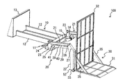
図2−図5は荷受台昇降装置100の斜視図であり、図2は荷受台30が展開姿勢にある状態、図3は荷受台30が接地してガイドローラ14(後述)に凭れた状態、図4は荷受台30が地面から離れてガイドローラ14に支持されている状態、図5は荷受台30が格納姿勢にある状態をそれぞれ表している。   2 to 5 are perspective views of the load receiving table elevating device 100. FIG. 2 is a state in which the load receiving stand 30 is in an unfolded position, and FIG. 4 shows a state in which the load receiving stage 30 is separated from the ground and is supported by the guide roller 14, and FIG. 5 shows a state in which the load receiving stage 30 is in the retracted position.

図2−図5に示したように、荷受台昇降装置100は、荷台3の床面に取り付けるベースユニット10と、このベースユニット10に取り付けられた左右のアームユニット20と、アームユニット20の先端部に取り付けた上記の荷受台30と、荷受台30を昇降させるリフト駆動装置40と、荷受台30を傾動させる傾動駆動装置50とを備えている。   As shown in FIGS. 2 to 5, the load receiving platform lifting device 100 includes a base unit 10 attached to the floor surface of the load carrier 3, left and right arm units 20 attached to the base unit 10, and the tip of the arm unit 20. The load receiving table 30 attached to the section, the lift driving device 40 that moves the load receiving table 30 up and down, and the tilt driving device 50 that tilts the load receiving table 30 are provided.

ベースユニット10は、荷台3の床面に当該ベースユニット10を取り付ける取り付け部11と、取り付け部11の前部に接続した縦根太12と、縦根太12の前部に接続したストッパ部材13とを備えている。取り付け部11は左右に延びる板状の部材で、荷台3の床面の後端付近にボルト等で固定されている。縦根太12は左右一対の梁状の部材であり、取り付け部11から前方に延在している。ストッパ部材13は、荷受台30の荷受台本体31(後述)との間に荷物の収容空間を画定する部材であり、図5に示したように、格納姿勢にある荷受台30の荷受台本体31の前方に対面するように、縦根太12の前端部に溶接等の手段で接合されて荷台3の内部に立設している。ストッパ部材13の前後位置、すなわち縦根太12の長さは、格納姿勢時の荷受台30の前端部にストッパ部材13の後面が当接若しくは近接する程度に設定されている。また、当該ベースユニット10の後端部、具体的には取り付け部11の後部には、格納姿勢又は展開姿勢に姿勢変位する荷受台30の背凭れ32(後述)をガイドするガイドローラ14が備えてられている。ガイドローラ14は、取り付け部11の後部に突設したブラケット15によって軸を水平にして回転自在に支持されており、本実施形態では左右2箇所に設置されていて、荷台3の開閉扉4を閉じても開閉扉4に接触しないように配置されている。   The base unit 10 includes an attachment portion 11 for attaching the base unit 10 to the floor surface of the loading platform 3, a vertical joist 12 connected to the front portion of the attachment portion 11, and a stopper member 13 connected to the front portion of the vertical joist 12. I have. The attachment portion 11 is a plate-like member extending left and right, and is fixed with a bolt or the like near the rear end of the floor surface of the loading platform 3. The vertical joists 12 are a pair of left and right beams, and extend forward from the mounting portion 11. The stopper member 13 is a member that demarcates a storage space for a load with a load receiving base 31 (described later) of the load receiving base 30, and as shown in FIG. 5, the load receiving main body of the load receiving base 30 in the retracted position. The front joist 12 is joined to the front end of the vertical joist 12 by means of welding or the like so as to face the front of 31 and is erected inside the cargo bed 3. The front-rear position of the stopper member 13, that is, the length of the vertical joist 12 is set such that the rear surface of the stopper member 13 is in contact with or close to the front end portion of the load receiving table 30 in the retracted posture. In addition, a guide roller 14 for guiding a backrest 32 (described later) of the load receiving table 30 that is displaced in the retracted posture or the deployed posture is provided at the rear end portion of the base unit 10, specifically, the rear portion of the attachment portion 11. It has been done. The guide roller 14 is rotatably supported with a horizontal axis by a bracket 15 projecting from the rear portion of the attachment portion 11. In this embodiment, the guide roller 14 is installed at two left and right sides, and the opening / closing door 4 of the loading platform 3 is attached to the guide roller 14. Even when closed, the door 4 is arranged so as not to contact the door 4.

なお、図の煩雑防止のため図2−図5では図示していないが、このベースユニット10には、格納姿勢の荷受台32を拘束するロック装置150が備えられている。ロック装置150については図7−図9を用いて後で説明する。   Although not shown in FIGS. 2 to 5 for the purpose of preventing the figure from being complicated, the base unit 10 is provided with a lock device 150 that restrains the load receiving platform 32 in the retracted position. The locking device 150 will be described later with reference to FIGS.

アームユニット20は、ベースユニット10に取り付けられた平行リンクアーム21と、この平行リンクアーム21の先端部にそれぞれ連結された支持アーム22とを備えている。平行リンクアーム21は、第1リンクアーム28及び第2リンクアーム29を有している。これらリンクアーム28,29の基端側は、ベースユニット10の取り付け部11上の左右両側に配置された基部ブラケット23にそれぞれピン24,25を介して連結されており、先端側は、上記支持アーム22の上部(基端部)にそれぞれピン26,27を介して連結されている。支持アーム22は、平行リンクアーム21との連結部から下方に延在している。平行リンクアーム21のピン24−27を結んで描かれる形状は平行四辺形状であり、文字通り平行リンクアーム21は平行リンクを構成し、荷台3の内部から後方に突出した位置(以下「下降位置」という)及び荷台3の内部で荷台3の床面から起立した位置(以下「上昇位置」という)の間で回動可能である。   The arm unit 20 includes a parallel link arm 21 attached to the base unit 10 and a support arm 22 connected to the distal end portion of the parallel link arm 21. The parallel link arm 21 has a first link arm 28 and a second link arm 29. The base ends of the link arms 28 and 29 are connected to base brackets 23 arranged on the left and right sides on the mounting portion 11 of the base unit 10 via pins 24 and 25, respectively, and the tip ends are supported by the above-described support. The arm 22 is connected to the upper part (base end part) via pins 26 and 27, respectively. The support arm 22 extends downward from the connecting portion with the parallel link arm 21. The shape drawn by connecting the pins 24-27 of the parallel link arm 21 is a parallelogram shape, and the parallel link arm 21 literally constitutes a parallel link and protrudes backward from the inside of the cargo bed 3 (hereinafter referred to as “lowering position”). And a position that stands up from the floor of the loading platform 3 (hereinafter referred to as an “upward position”) inside the loading platform 3.

また、第2リンクアーム29におけるピン25,27の間にはピン41が設けられていて、このピン41と第1リンクアーム28の先端の上記ピン26とに上記のリフト駆動装置40の両端がそれぞれ連結されている。この平行リンクアーム21に設けたリフト駆動装置40には、電動又は油圧のシリンダ(本実施形態では複動式の油圧シリンダ)が用いられるが、電動又は油圧のモータを適用することもできる。リフト駆動装置40の伸縮動作に伴って平行リンクアーム21が上記下降位置及び上昇位置の間で回動変位し、具体的にはリフト駆動装置40が伸長することで起立する方向(上昇位置方向)に、縮むことで後方(下降位置方向)に平行リンクアーム21が回動変位する。このとき、上記の通り平行リンクアーム21は平行リンクであるため、平行リンクアーム21が回動することによって、支持アーム22は上下に延びた姿勢を保ったまま弧状の軌跡を描いて上下動する(図1も併せて参照)。   A pin 41 is provided between the pins 25 and 27 of the second link arm 29, and both ends of the lift driving device 40 are connected to the pin 41 and the pin 26 at the tip of the first link arm 28. Each is connected. An electric or hydraulic cylinder (a double-acting hydraulic cylinder in the present embodiment) is used for the lift drive device 40 provided on the parallel link arm 21, but an electric or hydraulic motor can also be applied. The parallel link arm 21 is rotationally displaced between the lowered position and the raised position in accordance with the expansion / contraction operation of the lift driving device 40, and specifically, the direction in which the lift driving device 40 extends (the raised position direction). Further, the parallel link arm 21 is rotationally displaced rearward (downward position direction) by contracting. At this time, since the parallel link arm 21 is a parallel link as described above, when the parallel link arm 21 rotates, the support arm 22 moves up and down while drawing an arcuate locus while maintaining a vertically extended posture. (See also FIG. 1).

荷受台30は、荷受台本体31、及び荷受台本体31の前部に立設した背凭れ32でL字状に形成されている。荷受台本体31、背凭れ32ともほぼ同幅の板状の部材であり、筋交35によって強度が高められている。荷受台30のL字のコーナー部分(荷受台本体31と背凭れ32の境界部近傍)には回転軸33が左右に突出しており、この回転軸33が左右の支持アーム22の下端部(先端部)に貫通している。これによって荷受台30は、L字のコーナー部分で支持アーム22に軸支され、図2のように荷受台本体31を水平にした位置(以下「起立位置」という)、及び図5のように背凭れ32を寝かせた位置(以下「倒伏位置」という)の間で回動変位可能となっている。なお、倒伏位置を定義する背凭れ32を「寝かせた位置」とは、ここでは車両が走行する際の荷台3内における荷物の収納姿勢まで背凭れ32を寝かせた位置を意味し、通常は背凭れ32が水平になる位置を倒伏位置とするが、例えば内部に液体を貯留していて完全に水平に寝かせられない事情を有する荷物を積載する場合等に、背凭れ32が斜めになった姿勢も含み得る。   The load receiving stand 30 is formed in an L shape by a load receiving stand main body 31 and a backrest 32 erected on the front part of the load receiving stand main body 31. Both the load receiving table body 31 and the backrest 32 are plate-like members having substantially the same width, and the strength is enhanced by the brace 35. A rotation shaft 33 protrudes left and right at an L-shaped corner portion of the load receiving base 30 (near the boundary between the load receiving body 31 and the backrest 32), and the rotation shaft 33 is a lower end (front end) of the left and right support arms 22. Part). Accordingly, the load receiving platform 30 is pivotally supported by the support arm 22 at the L-shaped corner portion, and the load receiving platform main body 31 is horizontally positioned as shown in FIG. 2 (hereinafter referred to as “standing position”) and as shown in FIG. It can be rotated and displaced between positions where the backrest 32 is laid down (hereinafter referred to as “falling position”). Here, the “position where the backrest 32 defining the lying position is laid” means the position where the backrest 32 is laid down to the storage position of the luggage in the cargo bed 3 when the vehicle travels. Although the position where the droop 32 is horizontal is defined as the lying position, the posture in which the back 32 is inclined, for example, when loading a baggage that has a situation where liquid is stored inside and cannot be laid down completely horizontally May also be included.

また、背凭れ32の背面の上下方向の中間位置には、ブラケット34が左右に設けられていて、左右両側においてブラケット34と支持アーム22とに上記の傾動駆動装置50の両端がそれぞれピン51,52を介して連結されている。ピン52は支持アーム22の下部における回転軸33の前寄りの位置に貫通している。傾動駆動装置50には、電動又は油圧のシリンダ(本実施形態では複動式の油圧シリンダ)が用いられるが、電動又は油圧のモータを適用することもできる。傾動駆動装置50の伸縮動作に伴って荷受台30が回転軸33を中心に傾動し、具体的には傾動駆動装置50が伸長することで起立する方向に、縮むことで倒伏する方向に荷受台30が回動変位する。   Also, brackets 34 are provided on the left and right sides of the back surface of the backrest 32 in the vertical direction, and both ends of the tilt drive device 50 are connected to the brackets 51 and the support arm 22 on the left and right sides, respectively. They are connected via 52. The pin 52 passes through a position near the front of the rotating shaft 33 in the lower part of the support arm 22. An electric or hydraulic cylinder (in this embodiment, a double-acting hydraulic cylinder) is used for the tilting drive device 50, but an electric or hydraulic motor can also be applied. As the tilting drive device 50 expands and contracts, the load receiving platform 30 tilts about the rotation shaft 33. Specifically, the load receiving platform 30 extends in the direction of standing when the tilting driving device 50 extends, and in the direction of lying down when contracting. 30 is rotationally displaced.

ここで、図2−図5では図示していないが、荷受台30に対して着脱可能な荷物固定用の固定装置36,37(図6)や、格納姿勢の荷受台30を機械的に拘束するロック装置150(図7−図9)が備えられている。   Here, although not illustrated in FIGS. 2 to 5, the load fixing fixing devices 36 and 37 (FIG. 6) that can be attached to and detached from the load receiving table 30 and the load receiving table 30 in the retracted position are mechanically restrained. A locking device 150 (FIGS. 7 to 9) is provided.

図6は荷受台30とともに固定装置36,37を図示した斜視図である。この図では、筋交35や回転軸33、ブラケット34は図示省略している。   FIG. 6 is a perspective view illustrating fixing devices 36 and 37 together with the load receiving platform 30. In this figure, the bracing 35, the rotary shaft 33, and the bracket 34 are not shown.

図6に示したように、荷受台30には固定装置36,37を固定するための取り付け穴38が多数設けられている。本実施形態においては、背凭れ32に取り付け穴38を規則的に配列した場合を例示しているが、取り付け穴38の穿設位置や配列は特に限定されず、例えば荷受台本体部31にも取り付け穴38を設けることができる。固定装置36,37は、オプションであり、これら取り付け穴38に対してボルト及びナットで固定される。固定装置36,37の構成は特に限定されないが、荷受台30に搭載する荷物の固定姿勢等を考慮して決定される。例えば、荷受台30の格納動作時には荷物が傾動するので、この傾動動作中及び倒伏後の姿勢において荷物ががたつかないように、例えば背凭れ32と荷物との間の間隙を埋めて荷物を拘束するように固定装置36,37は適宜形成される。したがって、固定装置36,37を用いる場合、荷受台30が格納姿勢に移行したら、荷物は固定装置36,37を介して背凭れ32に支持される。特に図示していないが、固定装置36,37の固定に用いたもの以外の取り付け穴38は、ロープやバンド等の固縛手段の固定に使用することができ、固定装置36,37にセットした状態の荷物を固縛手段によって固定することができる。なお、本実施形態では2つ1組の固定装置36,37を例示しているが、固定装置の数は荷物の形状等に応じて変わり得る。   As shown in FIG. 6, the load receiving platform 30 is provided with a large number of mounting holes 38 for fixing the fixing devices 36 and 37. In the present embodiment, the case where the mounting holes 38 are regularly arranged in the backrest 32 is illustrated, but the drilling position and arrangement of the mounting holes 38 are not particularly limited. A mounting hole 38 can be provided. The fixing devices 36 and 37 are optional, and are fixed to the mounting holes 38 with bolts and nuts. The configuration of the fixing devices 36 and 37 is not particularly limited, but is determined in consideration of the fixing posture of the load mounted on the load receiving platform 30 and the like. For example, since the load is tilted during the storage operation of the load receiving platform 30, for example, the baggage is filled by filling a gap between the backrest 32 and the load so that the load does not rattle during the tilting operation and the posture after lying down. The fixing devices 36 and 37 are appropriately formed so as to be restrained. Therefore, when the fixing devices 36 and 37 are used, the load is supported on the backrest 32 via the fixing devices 36 and 37 when the cargo receiving platform 30 shifts to the retracted position. Although not particularly illustrated, the attachment holes 38 other than those used for fixing the fixing devices 36 and 37 can be used for fixing a securing means such as a rope or a band, and are set in the fixing devices 36 and 37. The state luggage can be secured by lashing means. In the present embodiment, two sets of fixing devices 36 and 37 are illustrated, but the number of fixing devices may vary depending on the shape of the luggage.

なお、図2−図5には図示していないが、本実施形態において、荷受台30には、背凭れ32に係止部39が設けられている。係止部39の構成は後述するロック装置150のフック152(図7等参照)が掛かるものであれば特に限定されないが、本実施形態においては、背凭れ32の上端部の左右両側の角部が切り欠かれていて、これら切り欠き部に左右方向に伸びるピンを設けることで、これを係止部39としている。   Although not shown in FIGS. 2 to 5, in the present embodiment, the receiving platform 30 is provided with a locking portion 39 on the backrest 32. The configuration of the locking portion 39 is not particularly limited as long as the hook 152 (see FIG. 7 and the like) of the locking device 150 to be described later is applied, but in the present embodiment, the corner portions on both the left and right sides of the upper end portion of the backrest 32. Are provided as a locking portion 39 by providing a pin extending in the left-right direction.

図7はベースユニット10とともにロック装置150の構成を表す側面図、図8はその平面図である。図7及び図8では図中の右左を前後としてある。   FIG. 7 is a side view showing the configuration of the locking device 150 together with the base unit 10, and FIG. 8 is a plan view thereof. 7 and 8, the right and left in the figure are front and rear.

図7及び図8に示したように、ロック装置150は、操作レバー151と、荷受台30の係止部39に係止するフック152と、操作レバー151の操作をフック152の動作に変換するリンク機構153とを備えている。   As shown in FIGS. 7 and 8, the lock device 150 converts the operation lever 151, the hook 152 to be engaged with the engagement portion 39 of the cargo receiving table 30, and the operation of the operation lever 151 into the operation of the hook 152. And a link mechanism 153.

操作レバー151は、ベースユニット10の取り付け部11の左右片側(本実施形態では右側)の端部に設けたボックス154に対し、左右方向に伸びる軸155を介して前後に回動するように設けられている。この操作レバー151は荷受台昇降装置100の後部に位置しているため、車両の荷台3の開閉扉4を開ければ無理なく作業者が手を掛けることができ、起立した位置(以下「ロック位置」という)にあるときには開閉扉4の可動領域に干渉しないが、後方に寝かせた位置(以下「ロック解除位置」という)にあるときにはガイドローラ14よりも後方に長さL(図7参照)だけ突出し開閉扉4の可動領域に干渉する。このようにロック解除位置にある操作レバー151を干渉させて開閉扉4を閉じられなくすることにより、開閉扉4を閉じることができない場合にロック装置150がロックされていない(ロック位置にない)ことが作業者に判るようになっている。   The operation lever 151 is provided so as to rotate back and forth via a shaft 155 extending in the left-right direction with respect to a box 154 provided on the left and right end portions (right side in the present embodiment) of the mounting portion 11 of the base unit 10. It has been. Since this operation lever 151 is located at the rear part of the load receiving platform lifting / lowering device 100, if the opening / closing door 4 of the loading platform 3 of the vehicle is opened, the operator can easily reach it, and the standing position (hereinafter referred to as “lock position”). Is not interfered with the movable region of the open / close door 4, but when it is at the rearward position (hereinafter referred to as “unlock position”), only the length L (see FIG. 7) behind the guide roller 14. It interferes with the movable region of the protruding door 4. Thus, the locking device 150 is not locked (not in the locking position) when the opening / closing door 4 cannot be closed by interfering with the operation lever 151 in the unlocking position to prevent the opening / closing door 4 from being closed. The worker can understand this.

なお、本実施形態では、ロック位置にあるときにロック装置150の操作レバー151が開閉扉4に干渉する構成としたが、開閉扉4に干渉させる部位は操作レバー151に限定されず、他の部位が開閉扉4に干渉する構成でも良いし、ロック位置にあるときに開閉扉4に干渉させるためだけに専用の部材を別途設けても良い。例えば、棒状で操作レバー151よりも長い当て部材を操作レバー151と平行に軸155に別途取り付け、操作レバー151をロック位置に操作したときに当て部材が操作レバー151よりも後方に突出するようにして、ロック位置にあるときには操作レバー151ではなく当て部材が開閉扉4に干渉する構成とすることが考えられる。この場合には、操作レバー151が開閉扉4に干渉しないので、ロック装置150を機能させる上で不可欠な部材である操作レバー151が開閉扉4との干渉によって損傷することを防止することができる。   In the present embodiment, the operation lever 151 of the locking device 150 interferes with the opening / closing door 4 when in the locked position, but the portion that interferes with the opening / closing door 4 is not limited to the operation lever 151, The part may interfere with the opening / closing door 4, or a dedicated member may be separately provided only to cause interference with the opening / closing door 4 when in the locked position. For example, a contact member that is rod-shaped and longer than the operation lever 151 is separately attached to the shaft 155 in parallel with the operation lever 151 so that the contact member protrudes rearward from the operation lever 151 when the operation lever 151 is operated to the lock position. Thus, it can be considered that the contact member, not the operation lever 151, interferes with the open / close door 4 when in the locked position. In this case, since the operation lever 151 does not interfere with the door 4, it is possible to prevent the operation lever 151 that is an indispensable member for causing the locking device 150 to function from being damaged by the interference with the door 4. .

リンク機構153は、複数のリンクアーム156−162を備えている。リンクアーム156は、軸155から操作レバー151と反対側に伸びており、リンクアーム157の一端に連結している。リンクアーム157の他端には、軸163に固定されたリンクアーム158に連結されている。軸163はボックス154の前部に設けた支持部材164及び取り付け部11に設けた支持部材165によって左右に延在する姿勢で回転自在に支持されている。軸163にはリンクアーム159を介してリンクアーム160が連結されており、さらにリンクアーム160には前後方向に延在するリンクアーム161の一端が連結されている。このリンクアーム161の他端は、軸166に固定されたリンクアーム162に連結されている。軸166は左右の縦根太12の前端部近傍を貫通して左右方向に延び、縦根太12に対して回転自在に支持されている。   The link mechanism 153 includes a plurality of link arms 156-162. The link arm 156 extends from the shaft 155 to the opposite side of the operation lever 151 and is connected to one end of the link arm 157. The other end of the link arm 157 is connected to a link arm 158 fixed to the shaft 163. The shaft 163 is rotatably supported in a posture extending left and right by a support member 164 provided at the front portion of the box 154 and a support member 165 provided at the attachment portion 11. A link arm 160 is connected to the shaft 163 via a link arm 159, and one end of a link arm 161 extending in the front-rear direction is connected to the link arm 160. The other end of the link arm 161 is connected to a link arm 162 fixed to the shaft 166. The shaft 166 passes through the vicinity of the front end portion of the left and right vertical joists 12 and extends in the left-right direction, and is supported rotatably with respect to the vertical joists 12.

上記フック152は、軸166に対して固定されている。フック152は左右に設けられていて、左側のフック152は左側の縦根太12の左側に、右側のフック152は右側の縦根太12の右側に位置している。そして、操作レバー151がロック位置(図7中の実線参照)からロック解除位置(図7中の一点鎖線参照)に倒伏すると、軸155、リンクアーム156−158、軸163、リンクアーム159−162及び軸166を介して操作レバー151の動きがフック162に伝達され、フック152が格納姿勢の荷受台30の係止部39(係止部39のみ図7に図示)に掛かり得るロック位置(図7中の実線参照)から係止部39を解放するロック解除位置(図7中の一点鎖線参照)に起立する。反対に、操作レバー151をロック解除位置からロック位置に起立させると、フック152はロック解除位置からロック位置に倒伏する。   The hook 152 is fixed to the shaft 166. The hooks 152 are provided on the left and right, the left hook 152 is positioned on the left side of the left vertical joist 12, and the right hook 152 is positioned on the right side of the right vertical joist 12. When the operation lever 151 falls from the locked position (see the solid line in FIG. 7) to the unlocked position (see the one-dot chain line in FIG. 7), the shaft 155, the link arm 156-158, the shaft 163, and the link arm 159-162. And the movement of the operating lever 151 is transmitted to the hook 162 via the shaft 166, and the hook 152 can be engaged with the locking portion 39 (only the locking portion 39 is shown in FIG. 7) of the load receiving base 30 in the retracted position (see FIG. 7). 7) (see a solid line in FIG. 7). On the other hand, when the operation lever 151 is raised from the unlocked position to the locked position, the hook 152 falls from the unlocked position to the locked position.

図9は操作レバー151の近傍の構成を表す拡大透視図である。   FIG. 9 is an enlarged perspective view showing a configuration in the vicinity of the operation lever 151.

図9に示したように、ボックス154の内壁にはロック装置150がロック位置又はロック解除位置にあることを検出するロックセンサ167が取り付けられている。ロックセンサ167には各種センサが適用可能であるが、本実施形態ではリミットスイッチを用いており、操作レバー151がロック解除位置に移行すると、操作レバー151と同方向に伸びるリンクアーム156に接触することによってリミットスイッチが入り、ロック装置150がロック解除位置にあることが検出されるようになっている。このロックセンサ167の検出信号は後述するコントローラ90に出力される。詳細は後述するが、このロックセンサ167からの信号を基にロック装置150がロック位置にあると判断された場合には、コントローラ90によってリフト駆動装置40及び傾動駆動装置50の動作が不能にされる。   As shown in FIG. 9, a lock sensor 167 that detects that the lock device 150 is in the locked position or the unlocked position is attached to the inner wall of the box 154. Various sensors can be applied to the lock sensor 167, but in this embodiment, a limit switch is used, and when the operation lever 151 moves to the unlocking position, it contacts the link arm 156 extending in the same direction as the operation lever 151. Accordingly, the limit switch is turned on, and it is detected that the lock device 150 is in the unlocked position. The detection signal of the lock sensor 167 is output to the controller 90 described later. Although details will be described later, when it is determined that the lock device 150 is in the lock position based on the signal from the lock sensor 167, the controller 90 disables the operations of the lift drive device 40 and the tilt drive device 50. The

なお、本実施形態ではリンクアーム156の姿勢変位をロックセンサ167で検出する構成としたが、直接操作レバー151の変位を検出する構成でも良いし、他のリンクアーム157−162やフック152の姿勢変位、又は軸155,163,166の回転角等を検出することでロック装置150がロック位置又はロック解除位置にあることを検出することができる。   In the present embodiment, the posture displacement of the link arm 156 is detected by the lock sensor 167. However, the displacement of the operation lever 151 may be directly detected, and the postures of the other link arms 157-162 and the hook 152 may be detected. By detecting the displacement or the rotation angle of the shafts 155, 163 and 166, it can be detected that the lock device 150 is in the lock position or the unlock position.

図10は荷受台昇降装置100に備えられたリフト駆動装置40及び傾動駆動装置50の油圧駆動装置の回路図である。   FIG. 10 is a circuit diagram of the hydraulic drive device of the lift drive device 40 and the tilt drive device 50 provided in the load receiving table lifting device 100.

図10の油圧駆動装置は、作動油を貯留するタンク61と、フィルタを介してタンク61の作動油を吸い上げて吐出する油圧ポンプ62と、この油圧ポンプ62を駆動する駆動装置(例えば電動モータ)60と、油圧ポンプ62の吐出管路63に並列に接続された上記のリフト駆動装置40及び傾動駆動装置50と、リフト駆動装置40及び傾動駆動装置50に対する作動油の流れを制御する3位置切換式のコントロールバルブ64,65とを備えている。   10 includes a tank 61 that stores hydraulic oil, a hydraulic pump 62 that sucks up and discharges the hydraulic oil in the tank 61 via a filter, and a drive device (for example, an electric motor) that drives the hydraulic pump 62. 60, the lift driving device 40 and the tilt driving device 50 connected in parallel to the discharge pipe 63 of the hydraulic pump 62, and a three-position switching for controlling the flow of hydraulic oil to the lift driving device 40 and the tilt driving device 50 Control valves 64 and 65 of the type.

コントロールバルブ64と左右のリフト駆動装置40のボトム側油室とを接続する作動油管路66には可変絞り型の絞り弁ユニット67が設けられていて、リフト駆動装置40のボトム側油室に供給する作動油、及び同油室から排出される作動油の流量が当該絞り弁ユニット67によって絞られる。また、コントロールバルブ65と左右の傾動駆動装置50のボトム側及びロッド側の油室とを接続する作動油管路68,69にも、可変絞り型の絞り弁ユニット70,71がそれぞれ設けられており、傾動駆動装置50のボトム側油室から排出される作動油、及びロッド側油室から排出される作動油の流量がそれぞれ絞り弁ユニット70,71によって絞られる。傾動駆動装置50の作動油管路68,69はバイパス管路72で接続されており、このバイパス管路72に設けた切換弁73を開くことで傾動駆動装置50はフリーの状態になる。   A variable throttle type throttle valve unit 67 is provided in the hydraulic oil line 66 that connects the control valve 64 and the bottom side oil chambers of the left and right lift driving devices 40, and is supplied to the bottom side oil chambers of the lift driving device 40. The flow rate of the working oil to be discharged and the working oil discharged from the oil chamber is throttled by the throttle valve unit 67. In addition, variable throttle type throttle valve units 70 and 71 are also provided in hydraulic oil pipes 68 and 69 that connect the control valve 65 and the bottom and rod side oil chambers of the left and right tilt drive devices 50, respectively. The flow rates of the hydraulic oil discharged from the bottom side oil chamber of the tilt drive device 50 and the hydraulic oil discharged from the rod side oil chamber are throttled by the throttle valve units 70 and 71, respectively. The hydraulic oil pipes 68 and 69 of the tilt driving device 50 are connected by a bypass pipe 72. By opening the switching valve 73 provided in the bypass pipe 72, the tilt driving device 50 becomes free.

また、吐出管路63は、コントロールバルブ64,65とタンク61とを接続する戻り管路74にリリーフ管路75,76を介して接続されている。一方のリリーフ管路75には回路保護用のリリーフ弁77が設けられていて、他方の低圧リリーフ管路76には低圧リリーフ弁78及び切換弁79が設けられている。低圧リリーフ弁78のリリーフ圧はリリーフ弁77のそれよりも低く設定されていて、切換弁79が開くことにより吐出管路63のリリーフ圧が低圧リリーフ弁78のリリーフ圧に低下する。   The discharge pipe 63 is connected to a return pipe 74 connecting the control valves 64 and 65 and the tank 61 via relief pipes 75 and 76. One relief pipe 75 is provided with a relief valve 77 for circuit protection, and the other low-pressure relief pipe 76 is provided with a low-pressure relief valve 78 and a switching valve 79. The relief pressure of the low pressure relief valve 78 is set lower than that of the relief valve 77, and the relief pressure of the discharge pipe 63 is reduced to the relief pressure of the low pressure relief valve 78 by opening the switching valve 79.

さらに、吐出管路63は、補助管路80を介してタンク61に接続しており、この補助管路80にはハンドポンプ81が設けられている。ハンドポンプ81を人力で駆動させることで、油圧ポンプ62が使用できない場合でも油圧駆動装置を駆動させることができる。   Further, the discharge pipe 63 is connected to the tank 61 via an auxiliary pipe 80, and a hand pump 81 is provided in the auxiliary pipe 80. By driving the hand pump 81 manually, the hydraulic drive device can be driven even when the hydraulic pump 62 cannot be used.

そして、コントロールバルブ64,65及び切換弁73,79は、荷受台昇降装置100に備えられたコントローラ(制御手段)90からの指令信号により切り換え制御される。このとき、特に図示していないが、荷受台昇降装置100には、平行リンクアーム21が上昇位置にないことを検出するアームセンサ、荷受台30の背凭れ32がガイドローラ14に接していることを検出するローラセンサ、及び荷受台30が地面に接地していることを検出する接地センサが設けられていて、アームセンサからの検出信号Sarm、接地センサからの検出信号Sgrd、ローラセンサからの検出信号Srolは、それぞれコントローラ90に入力される。コントローラ90は、後述する格納スイッチ97や展開スイッチ98からの操作信号を入力して荷受台30の格納動作又は展開動作を開始したら、動作中に入力される検出信号Sarm,Sgrd,Srolをトリガにしてコントロールバルブ64,65及び切換弁73,79への指令信号Ssol1−Ssol6を適宜出力する。これによって、コントローラ90は、リフト駆動装置40及び傾動駆動装置50を連動制御して荷受台30を展開姿勢と格納姿勢との間で姿勢変位させる。   The control valves 64 and 65 and the switching valves 73 and 79 are controlled to be switched by a command signal from a controller (control means) 90 provided in the cargo receiving table lifting device 100. At this time, although not particularly illustrated, the load receiving platform lifting / lowering device 100 has an arm sensor for detecting that the parallel link arm 21 is not in the raised position, and the backrest 32 of the load receiving platform 30 is in contact with the guide roller 14. And a ground sensor for detecting that the load receiving stand 30 is in contact with the ground, a detection signal Sarm from the arm sensor, a detection signal Sgrd from the ground sensor, and a detection from the roller sensor. Each signal Srol is input to the controller 90. When the controller 90 inputs an operation signal from a storage switch 97 or a deployment switch 98, which will be described later, and starts a storage operation or a deployment operation of the receiving platform 30, the detection signal Sarm, Sgrd, Srol input during the operation is used as a trigger. Then, command signals Ssol1-Ssol6 to the control valves 64, 65 and the switching valves 73, 79 are appropriately output. As a result, the controller 90 controls the lift drive device 40 and the tilt drive device 50 in conjunction with each other to displace the load receiving platform 30 between the deployed posture and the retracted posture.

指令信号Ssol1−Ssol6と、出力先/結果的動作の対応関係は次の通りである。   The correspondence relationship between the command signals Ssol1 to Ssol6 and the output destination / resulting operation is as follows.

Ssol1:コントロールバルブ64/リフト駆動装置40が伸長
Ssol2:コントロールバルブ64/リフト駆動装置40が縮退
Ssol3:コントロールバルブ65/傾動駆動装置50が伸長
Ssol4:コントロールバルブ65/傾動駆動装置50が縮退
Ssol5:切換弁79/リリーフ圧が低下
Ssol6:切換弁73/傾動駆動装置50がフリーになる
また、アームセンサとしては、例えば平行リンクアーム21のピン24−27のいずれかに設けた角度センサ、平行リンクアーム21と支持アーム22との距離を検出する近接センサ(距離センサ)等を用いることができる。接地センサとしては、荷受台30のコーナー部に地面との距離を検出する近接センサ(距離センサ)や、荷受台30のコーナー部が接地すると入るリミットスイッチ、平行リンクアーム21のピン24−27のいずれかに設けた角度センサ(アーム角度で荷受台30の高さを算出)等を用いることができる。ローラセンサとしては、ガイドローラと荷受台30の背凭れ32との距離を検出する近接センサ(距離センサ)、ガイドローラ14の支持部に設けた(ガイドローラ14に荷重がかかると入状態になる)リミットスイッチ等を用いることができる。
Ssol1: Control valve 64 / lift drive device 40 expands Ssol2: Control valve 64 / lift drive device 40 retracts Ssol3: Control valve 65 / tilt drive device 50 expands Ssol4: Control valve 65 / tilt drive device 50 retracts Ssol5: The switching valve 79 / relief pressure decreases Ssol6: the switching valve 73 / tilting drive device 50 becomes free. As an arm sensor, for example, an angle sensor or a parallel link provided on one of the pins 24-27 of the parallel link arm 21 A proximity sensor (distance sensor) that detects the distance between the arm 21 and the support arm 22 can be used. As a grounding sensor, a proximity sensor (distance sensor) that detects the distance to the ground at the corner of the load receiving table 30, a limit switch that enters when the corner of the load receiving table 30 contacts the ground, and pins 24-27 of the parallel link arm 21 An angle sensor provided in any of them (calculating the height of the load receiving platform 30 with the arm angle) or the like can be used. As a roller sensor, a proximity sensor (distance sensor) for detecting the distance between the guide roller and the backrest 32 of the load receiving table 30 is provided at a support portion of the guide roller 14 (when the load is applied to the guide roller 14, the roller sensor is turned on). ) A limit switch or the like can be used.

図11はコントローラ90に備えられたリレー回路の回路図である。   FIG. 11 is a circuit diagram of a relay circuit provided in the controller 90.

図11に示すリレー回路は、前述した駆動装置60及びロックセンサ167の他、上記アームセンサ、接地センサ及びローラセンサの検出信号が入ったらそれぞれ接点を閉じる接点91−93、荷受台昇降装置100の主電源スイッチ94、主電源が入っていることを報知音で報知するブザー(放置装置)95、ロックセンサ167が切れている(ロック装置150がロック解除位置にある)ことを報知音で報知するブザー(報知装置)96、格納動作を指示する格納スイッチ97、展開動作を指示する展開スイッチ98、リレーコイルR1〜R4,T1,T2,CT、及びこれらリレーコイルR1〜R4,T1,T2,CTが励磁されるとそれぞれ作動するリレー接点R1’〜R4’,T1’,T2’,CT’を備えている。   The relay circuit shown in FIG. 11 includes contacts 91-93 that close the contacts when the detection signals of the arm sensor, the ground sensor, and the roller sensor are received in addition to the driving device 60 and the lock sensor 167 described above, and the load receiving platform lifting device 100. A main power switch 94, a buzzer (leaving device) 95 for notifying that the main power is turned on with a notification sound, and a notification sound for notifying that the lock sensor 167 is off (the lock device 150 is in the unlocked position). Buzzer (notification device) 96, storage switch 97 for instructing the storage operation, expansion switch 98 for instructing the expansion operation, relay coils R1 to R4, T1, T2, CT, and these relay coils R1 to R4, T1, T2, CT Are provided with relay contacts R1 ′ to R4 ′, T1 ′, T2 ′, and CT ′, which are activated when excited.

上記リレー接点R2’は3つ存在するが、そのうちの2つは2接点を有する重複型の接点であり、リレーコイルR2が励磁されると2接点のいずれを選択的に入り状態とする。またリレーコイルT1,T2はオンディレータイマのコイルであり、励磁状態が設定時間継続すると励磁開始から設定時間経過後に対応するオンディレータイマ接点T1’,T2’が作動する。なお、主電源スイッチ94やブザー95は運転室2内に、格納スイッチ97及び展開スイッチ98は例えば荷台3内のリモコン等に配置されている。   Although there are three relay contacts R2 ', two of them are overlapping contacts having two contacts, and when the relay coil R2 is excited, either of the two contacts is selectively turned on. The relay coils T1 and T2 are on-delay timer coils. When the excitation state continues for a set time, the corresponding on-delay timer contacts T1 'and T2' are activated after the set time has elapsed since the start of excitation. The main power switch 94 and the buzzer 95 are disposed in the cab 2, and the storage switch 97 and the unfolding switch 98 are disposed, for example, on a remote controller in the loading platform 3.

次に上記構成の荷受台昇降装置100の動作及び作用効果を順次説明する。   Next, operations and effects of the load receiving table lifting apparatus 100 having the above-described configuration will be described in order.

1.展開動作
図12はコントローラ90による荷受台30の展開動作の制御手順を表す模式図、図13はコントロールバルブ64,65,73,79への指令信号の入り切りのタイミングチャートである。以下に図10及び図11を参照しつつ図12及び図13を用いて展開動作について説明する。
1. Deployment Operation FIG. 12 is a schematic diagram showing a control procedure of the deployment operation of the load receiving table 30 by the controller 90, and FIG. 13 is a timing chart of turning on / off command signals to the control valves 64, 65, 73, 79. The unfolding operation will be described below using FIGS. 12 and 13 with reference to FIGS.

(ステップA)
荷受台昇降装置100を操作するには、まず運転室2内で荷受台昇降装置100の主電源スイッチ94をON(入)にする。主電源が入ると、図11のリレー回路に示したようにブザー95に通電されることによって運転室2内に報知音が出力され、主電源が入っていることが運転室1内に報知される。この報知音は主電源スイッチ94が入っている間継続的に鳴動する。次に、車両の後部に回って荷台3の開閉扉4を開き、ロック装置150の操作レバー151をロック解除位置に倒伏させる。これによりロックセンサ167がONになり、ブザー96に通電されることによって車両後方に報知音が出力され、ロック装置150がロック解除位置にあることが車両の周囲に報知される。この報知音はロック装置150がロック解除位置にある間継続的に鳴動する。この時点では荷受台30は格納姿勢にあり、検出信号Sarm,Sgrd,SrolはいずれもOFF(切)の状態である。
(Step A)
In order to operate the load receiving platform lifting apparatus 100, first, the main power switch 94 of the load receiving platform lifting apparatus 100 is turned on in the cab 2. When the main power is turned on, as shown in the relay circuit of FIG. 11, the buzzer 95 is energized to output a notification sound in the cab 2 and to notify the cab 1 that the main power is turned on. The This notification sound sounds continuously while the main power switch 94 is on. Next, it turns to the rear part of the vehicle, opens the opening / closing door 4 of the loading platform 3, and causes the operation lever 151 of the locking device 150 to fall to the unlocking position. As a result, the lock sensor 167 is turned on, and when the buzzer 96 is energized, a notification sound is output to the rear of the vehicle, and it is notified to the surroundings of the vehicle that the lock device 150 is in the unlocked position. This notification sound sounds continuously while the lock device 150 is in the unlocked position. At this time, the receiving platform 30 is in the retracted position, and the detection signals Sarm, Sgrd, and Srol are all in an OFF (off) state.

次に展開スイッチ98を操作すると、コントローラ90は、指令信号Ssol2,Ssol6をコントロールバルブ64及び切換弁73に出力し、コントロールバルブ64を図10中の左側のポジション、切換弁73を上側のポジションに切り換える。これによってリフト駆動装置40のロッド側油室が油圧ポンプ62の吐出管路63に接続し、傾動駆動装置50のボトム側及びロッド側の作動油管路68,69が接続する。同時に、コンタクタリレーコイルCTが励磁されてコンタクタリレー接点CT’が閉じ、駆動装置60が駆動して油圧ポンプ62が駆動する。これにより、リフト駆動装置40が縮退動作するとともに、傾動駆動装置50がフリー(伸縮自在な状態)となる。その結果、荷受台30が、平行リンクアーム21に吊り上げられて背凭れ32が縦根太12から僅かに浮き上がった後、後方に下降し始める。ステップAが実行されると、平行リンクアーム21が上昇位置から動き出し平行リンクアーム21が上昇位置を脱したことで、直ぐにアームセンサからの検出信号SarmがON(入)になり、ステップBに手順が移行する。なお、図12中では検出信号Sarm,Srol,SgrdのON/OFFをそれぞれ「○」の有無で表示している。後述の図14も同様である。   Next, when the expansion switch 98 is operated, the controller 90 outputs the command signals Ssol2 and Ssol6 to the control valve 64 and the switching valve 73. The control valve 64 is set to the left position in FIG. 10, and the switching valve 73 is set to the upper position. Switch. As a result, the rod side oil chamber of the lift drive unit 40 is connected to the discharge line 63 of the hydraulic pump 62, and the bottom side and rod side hydraulic oil lines 68 and 69 of the tilt drive unit 50 are connected. At the same time, the contactor relay coil CT is excited to close the contactor relay contact CT ', the drive device 60 is driven, and the hydraulic pump 62 is driven. As a result, the lift drive device 40 is retracted and the tilt drive device 50 is free (expandable state). As a result, after the load receiving platform 30 is lifted by the parallel link arm 21 and the backrest 32 is slightly lifted from the vertical joist 12, it starts to descend rearward. When step A is executed, the parallel link arm 21 starts to move from the raised position, and the parallel link arm 21 leaves the raised position, so that the detection signal Sarm from the arm sensor is immediately turned ON (on), and the procedure goes to step B. Will migrate. In FIG. 12, ON / OFF of the detection signals Sarm, Srol, and Sgrd is indicated by the presence or absence of “◯”. The same applies to FIG. 14 described later.

(ステップB)
ステップBでは、アームセンサからの検出信号Sarmが入って接点91が閉じることで、リレーコイルR1が励磁され、対応するリレー接点R1’が作動する。これにより、コントローラ90から切換弁73に指令信号Ssol3が出力され、コントロールバルブ65を図10中の右側のポジションに切り換える。これによって傾動駆動装置50のボトム側及びロッド側の作動油管路68,69がタンク61に接続し、傾動駆動装置50の従動性が増す。指令信号Ssol2,Ssol6は継続して出力される。これによって荷受台30は、平行リンクアーム21の動作に伴って支持アーム22とともに荷台3から繰り出して後方に移動しながら弧状の軌跡を描いて下降する。この下降速度は、絞り弁ユニット67の作用によって緩やかに抑えられる。
(Step B)
In Step B, when the detection signal Sarm from the arm sensor is entered and the contact 91 is closed, the relay coil R1 is excited and the corresponding relay contact R1 ′ is activated. As a result, the command signal Ssol3 is output from the controller 90 to the switching valve 73, and the control valve 65 is switched to the right position in FIG. As a result, the bottom side and rod side hydraulic oil pipes 68 and 69 of the tilt drive device 50 are connected to the tank 61, and the followability of the tilt drive device 50 is increased. The command signals Ssol2 and Ssol6 are continuously output. As a result, the load receiving platform 30 descends from the loading platform 3 together with the support arm 22 in accordance with the operation of the parallel link arm 21 and moves backward while drawing an arcuate locus. This descending speed is moderately suppressed by the action of the throttle valve unit 67.

なお、例えばこのステップB及び次のステップCにおいては、リフト駆動装置40には荷受台30等の自重の作用が加わって縮む方向に付勢力が作用する。したがって、積極的にロッド側油室に作動油を供給しなくても、ボトム側油室がタンク61に接続しているので荷受台30等の自重で展開方向に動作する。したがって、油圧ポンプ62のピストン動作に起因する作動油の脈動により下降動作時に荷受台30に発生し得る微細な振動を抑制するため、荷受台30を下降させる際には油圧ポンプ62の回転数を落とす等して吐出流量を下げ、下降動作の駆動源として荷受台30等の重量が支配的となるようにすることも考えられる。   For example, in this step B and the next step C, the lift driving device 40 is subjected to an urging force in a direction in which the lift driving device 40 contracts due to the action of its own weight such as the load receiving platform 30. Therefore, even if hydraulic oil is not positively supplied to the rod side oil chamber, the bottom side oil chamber is connected to the tank 61, so that it operates in the unfolding direction with its own weight such as the load receiving platform 30. Therefore, in order to suppress minute vibrations that may occur in the load receiving platform 30 during the lowering operation due to the pulsation of the hydraulic oil caused by the piston operation of the hydraulic pump 62, the rotational speed of the hydraulic pump 62 is reduced when the load receiving platform 30 is lowered. It is also conceivable to reduce the discharge flow rate by dropping it so that the weight of the load receiving platform 30 or the like becomes dominant as a driving source for the lowering operation.

(ステップC)
ステップBの実行後、直ぐに荷受台30の背凭れ32がガイドローラ14に当接する。これによってローラセンサからの検出信号Srolが入って接点93が閉じ、リレーコイルR3,T2が励磁されてリレー接点R3’,T2’が作動するが、展開動作時には指令信号の出力状態は変化しない。指令信号Ssol2,Ssol3,Ssol6の出力状態を維持したまま、さらに支持アーム22が下降するにつれて背凭れ32がガイドローラ14に倣って起立していく。そして、支持アーム22がさらに下降して荷受台30のコーナー部が地面に接地すると、接地センサからの検出信号SgrdがON(入)になり、続くステップDに手順が移行する。
(Step C)
Immediately after the execution of Step B, the backrest 32 of the load receiving table 30 comes into contact with the guide roller 14. As a result, the detection signal Srol from the roller sensor is entered, the contact 93 is closed, the relay coils R3 and T2 are excited and the relay contacts R3 ′ and T2 ′ are activated, but the output state of the command signal does not change during the unfolding operation. While the output states of the command signals Ssol2, Ssol3, and Ssol6 are maintained, the backrest 32 rises following the guide roller 14 as the support arm 22 is further lowered. When the support arm 22 further descends and the corner portion of the load receiving platform 30 contacts the ground, the detection signal Sgrd from the ground sensor is turned on (ON), and the procedure proceeds to the subsequent step D.

(ステップD,E)
ステップDでは、接地センサからの検出信号Sgrdが入って接点92が閉じ、リレーコイルR2,T1が励磁される。これにより、まずリレー接点R2’が作動し、切換弁79に指令信号Ssol5が出力され、切換弁79が図10中の上側のポジションに切り換わる。これにより油圧駆動装置の油圧回路のリリーフ圧が低圧リリーフ弁78による低圧のリリーフ圧に切り換わり、荷受台30と地面との間に過度の押しつけ力が働かないようになる。そして、リレーコイルT1が励磁されて設定時間t1が経過するとオンディレータイマ接点T1’が開き、指令信号Ssol6の出力が停止されることで切換弁73が図10中下側のポジションに復帰する。これによって傾動駆動装置50がフリーの状態を脱して伸長動作を開始し、ガイドローラ14に凭れた姿勢から荷受台30がコーナー部を始点にして展開姿勢(ステップE)に移行する。この間、すなわち接地センサから検出信号Sgrdが入力されている間、コントローラ90は切換弁79を開放してリリーフ圧を下げた状態を維持する。
(Steps D and E)
In Step D, the detection signal Sgrd from the ground sensor is entered, the contact 92 is closed, and the relay coils R2 and T1 are excited. As a result, the relay contact R2 ′ is first activated, the command signal Ssol5 is output to the switching valve 79, and the switching valve 79 is switched to the upper position in FIG. As a result, the relief pressure of the hydraulic circuit of the hydraulic drive device is switched to a low-pressure relief pressure by the low-pressure relief valve 78, and an excessive pressing force does not act between the load receiving platform 30 and the ground. When the relay coil T1 is excited and the set time t1 elapses, the on-delay timer contact T1 ′ is opened, and the output of the command signal Ssol6 is stopped, so that the switching valve 73 returns to the lower position in FIG. As a result, the tilting drive device 50 is released from the free state and starts to extend, and the load receiving platform 30 shifts from the posture of the guide roller 14 to the deployed posture (step E) starting from the corner portion. During this time, that is, while the detection signal Sgrd is input from the ground sensor, the controller 90 opens the switching valve 79 and maintains the state where the relief pressure is lowered.

そして、荷受台30が起立位置に達して荷受台30が展開姿勢に移行した後、展開スイッチ98の操作を止めると、コントローラ90は、出力中の指令信号Ssol2,Ssol3,Ssol5を停止して荷受台30の展開動作を終了する。   When the operation of the deployment switch 98 is stopped after the load receiving table 30 reaches the standing position and the load receiving table 30 shifts to the deployed position, the controller 90 stops the command signals Ssol2, Ssol3, Ssol5 being output and receives the load. The unfolding operation of the table 30 is finished.

なお、ローラセンサからの検出信号Srolが切れることでリレーコイルR3が励磁されなくなり、リレー接点R3’が作動するが、ステップDの時点では指令信号の出力状態に影響しない。また、ステップDの実行は、例えば予め設定された時間T0に制限され、ステップDの実行開始後設定時間T0が経過したら、コントローラ90は、出力中の指令信号Ssol2,Ssol3,Ssol5を停止して荷受台30の展開動作を終了する。なお、時間T0は、例えば、荷受台30が地面とガイドローラ14に接した状態から荷受台本体31の底面で接地して起立した状態(展開姿勢)に移行するのに要する時間等である。   Note that when the detection signal Srol from the roller sensor is cut off, the relay coil R3 is not excited and the relay contact R3 'operates, but at the time of step D, the output state of the command signal is not affected. Further, the execution of step D is limited to, for example, a preset time T0. When the set time T0 has elapsed after the start of execution of step D, the controller 90 stops the command signals Ssol2, Ssol3, Ssol5 being output. The unfolding operation of the receiving platform 30 is finished. The time T0 is, for example, the time required to shift from a state where the load receiving table 30 is in contact with the ground and the guide roller 14 to a state where the load receiving table 30 is in contact with the bottom surface of the load receiving table main body 31 and stands up (deployed posture).

2.格納動作
図14はコントローラ90による荷受台30の格納動作の制御手順を表す模式図、図15はコントロールバルブ64,65,73,79への指令信号の入り切りのタイミングチャートである。以下に図10及び図11を参照しつつ図14及び図15を用いて格納動作について説明する。
2. Storage Operation FIG. 14 is a schematic diagram showing a control procedure of the storage operation of the cargo receiving platform 30 by the controller 90, and FIG. 15 is a timing chart of turning on and off command signals to the control valves 64, 65, 73, and 79. The storing operation will be described below with reference to FIGS. 14 and 15 with reference to FIGS.

(ステップF)
この時点では荷受台30は展開姿勢にあり、検出信号Sarm,SgrdがON、検出信号SrolがOFFの状態である。コントローラ90は、格納スイッチ97が操作されると、コントローラ90は、指令信号Ssol4をコントロールバルブ65に出力し、コントロールバルブ65を図10中の左側のポジションに切り換える。これによって傾動駆動装置50のロッド側油室が油圧ポンプ62の吐出管路63に接続する。同時に、コンタクタリレーコイルCTが励磁されてコンタクタリレー接点CT’が閉じ、駆動装置60が駆動して油圧ポンプ62が駆動する。これにより、傾動駆動装置50が縮退動作し、荷受台30がコーナー部で接地した状態で格納方向に回動してガイドローラ14に凭れ掛かる。荷受台30の背凭れ32がガイドローラ14に凭れ掛かってローラセンサの検出信号SrolがONになると、コントローラ90は、手順をステップGに移す。
(Step F)
At this time, the load receiving stand 30 is in the unfolded posture, and the detection signals Sarm and Sgrd are ON and the detection signal Srol is OFF. When the retract switch 97 is operated, the controller 90 outputs the command signal Ssol4 to the control valve 65, and switches the control valve 65 to the left position in FIG. As a result, the rod side oil chamber of the tilt drive device 50 is connected to the discharge pipe 63 of the hydraulic pump 62. At the same time, the contactor relay coil CT is excited to close the contactor relay contact CT ′, the drive device 60 is driven, and the hydraulic pump 62 is driven. As a result, the tilting drive device 50 is retracted, and in the state where the load receiving platform 30 is grounded at the corner portion, the tilting drive device 50 rotates in the retracted direction and hangs on the guide roller 14. When the backrest 32 of the load receiving platform 30 leans on the guide roller 14 and the detection signal Srol of the roller sensor is turned on, the controller 90 moves the procedure to Step G.

(ステップG−J)
ステップGでは、ローラセンサからの検出信号Srolが入って接点93が閉じ、リレーコイルR3,T2が励磁される。これにより、まずリレー接点R3’が作動し、切換弁73に指令信号Ssol6が出力されて、切換弁73が図10中の上側のポジションに切り換わる。これにより傾動駆動装置50が一旦フリーになって自重でガイドローラ14に荷受台30が立て掛かった状態となる。そして、リレーコイルT2が励磁されて設定時間t2(t1と同じ長さでも異なる長さでも良い)が経過するとオンディレータイマ接点T2’が閉じ、コントロールバルブ64に指令信号Ssol1が出力され、コントロールバルブ64が図10中の右側のポジションに切り換わり、リフト駆動装置40が伸長動作を開始する。同時に、指令信号Ssol6の出力が停止され、切換弁73が下側の遮断位置に復帰することにより、傾動駆動装置50が倒伏側に動作し、荷受台30の背凭れ32がガイドローラ14に押し付けられる。このように、荷受台30は、ガイドローラ14に押し付けられながら上昇していく。
(Step GJ)
In Step G, the detection signal Srol from the roller sensor is entered, the contact 93 is closed, and the relay coils R3 and T2 are excited. As a result, the relay contact R3 ′ is first activated, the command signal Ssol6 is output to the switching valve 73, and the switching valve 73 is switched to the upper position in FIG. As a result, the tilting drive device 50 becomes free once, and the load receiving platform 30 stands against the guide roller 14 by its own weight. When the relay coil T2 is excited and a set time t2 (which may be the same length as t1 or a different length) elapses, the on-delay timer contact T2 ′ is closed, and the command signal Ssol1 is output to the control valve 64, and the control valve 64 switches to the right position in FIG. 10, and the lift driving device 40 starts the extending operation. At the same time, the output of the command signal Ssol6 is stopped, and the switching valve 73 returns to the lower shut-off position, whereby the tilting drive device 50 operates on the sloping side, and the backrest 32 of the load receiving table 30 is pressed against the guide roller 14. It is done. In this way, the load receiving platform 30 moves upward while being pressed against the guide roller 14.

この格納動作の進展に伴って接地センサ及びローラセンサからの検出信号Sgrd,Srolが順次OFFになり(ステップH,I)、アームセンサからの検出信号SarmがONになるが(ステップJ)、図11のリレー回路の通り、この間に指令信号の出力状態が切り換わることはなく、指令信号Ssol1,Ssol4の出力が維持される。荷受台本体31よりも長さのある背凭れ32がガイドローラ14に接した状態では、荷受台30の重心はその回動軸33よりも前方にあるため、支持アーム22とともに弧状に上昇する過程で、自重によっても荷受台30はガイドローラ14に倣いつつ格納方向に傾動していく。   As the storage operation progresses, the detection signals Sgrd and Srol from the ground sensor and roller sensor are sequentially turned off (steps H and I), and the detection signal Sarm from the arm sensor is turned on (step J). As in 11 relay circuit, the output state of the command signal is not switched during this time, and the output of the command signals Ssol1 and Ssol4 is maintained. In a state in which the backrest 32 having a length longer than that of the load receiving body 31 is in contact with the guide roller 14, the center of gravity of the load receiving stand 30 is in front of the rotation shaft 33, and thus the process of rising in an arc with the support arm 22. Thus, the load receiving platform 30 also tilts in the retracted direction while following the guide roller 14 due to its own weight.

そして、平行リンクアーム21が上昇姿勢に達して荷受台30が格納姿勢に移行した後、格納スイッチ97の操作を止めると、コントローラ90は、出力中の指令信号Ssol1,Ssol4を停止して荷受台30の格納動作を終了する。格納動作時にも、荷受台30の上昇速度、傾動速度は絞り弁ユニット67,70,71の作用により緩やかに抑えられている。   When the operation of the storage switch 97 is stopped after the parallel link arm 21 reaches the ascending posture and the load receiving table 30 shifts to the retracted posture, the controller 90 stops the output command signals Ssol1 and Ssol4 and stops the load receiving table. 30 storing operation is completed. Even during the storage operation, the ascending speed and the tilting speed of the load receiving platform 30 are moderately suppressed by the action of the throttle valve units 67, 70, 71.

格納動作が完了したら、ロック装置150、ロック装置150の操作レバー151をロック位置に起立させ、荷受台30の背凭れ32をフック152で拘束する。これによりロックセンサ167がOFFになり、ブザー96への電路が遮断されてブザー96の鳴動が停止する。その後、荷台3の開閉扉4を閉じて運転室2に戻り、主電源スイッチ94をOFF(切)にする。主電源が切れると、ブザー95への電路が遮断されてブザー95の鳴動が停止する。   When the storage operation is completed, the lock device 150 and the operation lever 151 of the lock device 150 are raised at the lock position, and the backrest 32 of the load receiving platform 30 is restrained by the hook 152. As a result, the lock sensor 167 is turned off, the electric path to the buzzer 96 is interrupted, and the buzzer 96 stops ringing. Thereafter, the opening / closing door 4 of the cargo bed 3 is closed and the operation room 2 is returned to, and the main power switch 94 is turned off. When the main power is turned off, the electric circuit to the buzzer 95 is interrupted and the buzzer 95 stops ringing.

続けて本実施形態により得られる作用効果を説明する。   Next, operational effects obtained by this embodiment will be described.

(1)上記のように、本実施形態では、傾動駆動装置50を設けたので、展開時に荷受台30をガイドローラ14から起こす動作や格納時に荷受台30をガイドローラ14に立て掛ける動作を傾動駆動装置50で行うことができ、人手作業を不要にすることができる。また、コントローラ90によってリフト駆動装置40及び傾動駆動装置50の動作が接地センサやローラセンサ等の検出信号をトリガとして自動的に切り換わり連続的に実行されるので、格納スイッチ97及び展開スイッチ98の継続的な一操作によって一連の展開動作及び格納動作をそれぞれ完結させることができる。これによって人手作業の煩わしさを軽減することができる。   (1) As described above, since the tilt drive device 50 is provided in the present embodiment, the operation of raising the load receiving platform 30 from the guide roller 14 during deployment and the operation of leaning the load receiving platform 30 against the guide roller 14 during storage are tilt driven. This can be performed by the apparatus 50, and manual work can be eliminated. Further, the controller 90 automatically switches the operation of the lift drive device 40 and the tilt drive device 50 using the detection signals from the ground sensor, roller sensor, etc. as a trigger, and is executed continuously. A series of unfolding operations and storage operations can be completed by one continuous operation. This can reduce the troublesome manual work.

加えて、本実施形態の場合、コントローラ90は、展開動作時において、荷受台30の下降中に接地センサからの検出信号Sgrdが入力されたら、設定時間t1が経過するのを待って傾動駆動装置50を駆動し荷受台30を起立位置に向けて傾動させる(ステップD)。格納動作時においては、荷受台30が接地した状態で倒伏位置に向けて傾動している中にローラセンサからの検出信号Srolが入力されたら、設定時間t2が経過するのを待ってリフト駆動装置40を駆動して荷受台30を上昇させる(ステップG)。   In addition, in the case of the present embodiment, the controller 90 waits for the set time t1 to elapse when the detection signal Sgrd from the ground sensor is input while the load receiving platform 30 is lowered during the unfolding operation. 50 is driven to tilt the load receiving table 30 toward the standing position (step D). During the retracting operation, when the detection signal Srol is input from the roller sensor while the load receiving platform 30 is tilted toward the lying down position, the lift driving device waits for the set time t2 to elapse. 40 is driven to raise the receiving platform 30 (step G).

すなわち、展開動作中においては、荷受台30が接地するよりも僅かに早く接地センサの検出信号Sgrdが入力されたとしても、直ちに傾動駆動装置50の動作指令を出力せず、検出信号Sgrdが入力されてから設定時間t1だけ遅れて傾動駆動装置50の動作を指令する。設定時間t1は検出信号Sgrdの出力のタイミングと現実に荷受台30が接地するタイミングとの間に生じ得るずれ時間よりも長い時間であり、検出信号Sgrdが入力されてから設定時間t1が経過するのを待ってコントロールバルブ65への信号Ssol5を出力することにより、検出信号Sgrdが入力されるタイミングと荷受台30が現実に接地するタイミングにずれが生じても、そのずれ時間を設定時間t1で吸収することができる。したがって、荷受台30が接地する前に検出信号Sgrdが入力されたとしても、現実に荷受台30が設置する前に荷受台30が傾動し始めることを回避し、荷受台30が確実に接地してから荷受台30を傾動させることができる。そのため、例えば接地前に傾動駆動装置50が駆動し始めることによって荷受台30が宙に浮いた状態で傾転し出すことを回避することができ、荷受台30に搭載した荷物の安定性に関して信頼性を確保することができる。   That is, during the unfolding operation, even if the detection signal Sgrd of the grounding sensor is input slightly earlier than the load receiving platform 30 is grounded, the operation command of the tilt driving device 50 is not immediately output, and the detection signal Sgrd is input. After that, the operation of the tilt drive device 50 is commanded with a delay of the set time t1. The set time t1 is a time longer than a deviation time that may occur between the output timing of the detection signal Sgrd and the timing at which the receiving platform 30 is actually grounded, and the set time t1 elapses after the detection signal Sgrd is input. When the signal Ssol5 is output to the control valve 65 after waiting for this, even if a deviation occurs between the timing at which the detection signal Sgrd is input and the timing at which the load receiving platform 30 is actually grounded, the deviation time is set at the set time t1. Can be absorbed. Therefore, even if the detection signal Sgrd is input before the load receiving table 30 is grounded, the load receiving table 30 is prevented from starting to tilt before the load receiving table 30 is actually installed, and the load receiving table 30 is securely grounded. After that, the receiving platform 30 can be tilted. Therefore, for example, when the tilting drive device 50 starts to be driven before the ground contact, it is possible to avoid the load receiving table 30 from tilting in a suspended state, and the reliability of the load mounted on the load receiving table 30 is reliable. Sex can be secured.

また、例えば車両から荷物を降ろしたり作業者が車両から降りたりすると、その分だけ車両の積載重量が軽くなるので、僅かながらも車両のサスペンションが伸びて車両(シャシフレーム1)の高さが上昇する。そのため、荷受台30が展開して当初接地した状態にあっても、荷物を降ろしたり作業者が降りたりして車両が浮き上がると、車両に追従して荷受台30も浮き上がり地面から離れてしまい得る。これは荷受台昇降装置としては大きなデメリットである。   Further, for example, when a load is unloaded from a vehicle or an operator gets off the vehicle, the loaded weight of the vehicle is reduced accordingly, so that the suspension of the vehicle extends slightly and the height of the vehicle (chassis frame 1) increases. To do. For this reason, even when the cargo cradle 30 is unfolded and initially in a grounded state, if the vehicle is lifted by unloading a load or an operator getting off, the cradle 30 may also follow the vehicle and lift away from the ground. . This is a great demerit as a cargo receiving elevating device.

それに対し本実施形態では、展開動作時において接地後荷受台30を傾転させる前に設定時間t1だけ荷受台30を地面に押し付けるので、この設定時間t1の間に車両を若干浮かせておくことができる。これにより、その後、荷物等を車両から降ろした際に、車両に伴って荷受台30が地面から浮き上がることを抑えることができる。   On the other hand, in the present embodiment, since the load receiving platform 30 is pressed against the ground for the set time t1 before the post-contacting load receiving platform 30 is tilted during the unfolding operation, the vehicle may be slightly floated during the set time t1. it can. Thereby, when a luggage | load etc. are dropped from a vehicle after that, it can suppress that the load receiving stand 30 floats from the ground with a vehicle.

一方、格納動作時においても、ローラセンサからの検出信号Srolが入力されてから設定時間t2だけ遅れてリフト駆動装置40の動作を指令する。設定時間t2は検出信号Srolの出力のタイミングと現実に荷受台30がガイドローラ14に接触するタイミングとの間に生じ得るずれ時間よりも長い時間であり、検出信号Srolが入力されるタイミングと荷受台30が現実にガイドローラ14に接触するタイミングにずれが生じても、そのずれ時間を設定時間t2で吸収することができるので、現実に荷受台30がガイドローラ14に接触する前に荷受台30が上昇し始めることを回避し、荷受台30が確実にガイドローラ15に接触してから荷受台30を上昇させることができる。そのため、例えばガイドローラ14に接触する前にリフト駆動装置40が駆動し始めることによって荷受台30が不安定な状態で宙に浮くことを回避することができ、荷受台30に搭載した荷物の安定性に関して信頼性を確保することができる。   On the other hand, even during the retracting operation, the operation of the lift driving device 40 is commanded with a delay of the set time t2 after the detection signal Srol from the roller sensor is input. The set time t2 is longer than the deviation time that may occur between the output timing of the detection signal Srol and the timing at which the load receiving table 30 actually contacts the guide roller 14, and the timing and the reception of the detection signal Srol. Even if there is a deviation in the timing at which the platform 30 actually contacts the guide roller 14, the deviation time can be absorbed at the set time t <b> 2, so the cargo receiving platform 30 actually contacts the guide roller 14 before the loading platform 30 contacts the guide roller 14. It is possible to avoid starting 30 from rising, and to raise the load receiving table 30 after the load receiving table 30 is reliably in contact with the guide roller 15. Therefore, for example, when the lift driving device 40 starts to be driven before coming into contact with the guide roller 14, it is possible to prevent the load receiving table 30 from floating in the air in an unstable state, and the stability of the load loaded on the load receiving table 30 can be prevented. Reliability can be ensured with respect to performance.

このように規定の動作を確実に再現することができるので、本実施形態によれば、動作の高い信頼性を確保することができ、また急な動作切り換えによる異音発生を抑制することもできる。したがって、荷受台30の傾動を含めた一連の格納動作又は展開動作を自動化して作業者の負担を軽減しつつ、一連の動作の高い信頼性を確保して作業者の心理的負担を軽減することができる。   Since the specified operation can be reliably reproduced as described above, according to the present embodiment, high reliability of the operation can be ensured, and generation of abnormal noise due to sudden operation switching can be suppressed. . Therefore, while automating a series of storage operations or unfolding operations including tilting of the load receiving platform 30 to reduce the burden on the operator, the reliability of the series of operations is ensured and the psychological burden on the operator is reduced. be able to.

(2)また、本実施形態によれば、荷受台30が地上で起立した展開姿勢から上昇しながら倒伏して荷台3内で倒伏した格納姿勢に移行するので、長尺の荷物を荷受台30に立てた状態で積み込み、荷受3に寝かせた状態で収容することができる。特に、本実施形態のように車両の荷台3が荷箱である場合、すなわち荷台3に天井がある場合、本実施形態のように荷物を昇降させながら傾斜させることで、荷台3の天井との干渉を回避しながら荷物を荷台3に積み込むことができる。   (2) Further, according to the present embodiment, since the load receiving platform 30 rises from the deployed posture standing on the ground and falls to the retracted posture in the load loading platform 3, a long load is loaded on the load receiving platform 30. It can be loaded in a standing state and can be accommodated in a state in which it is laid down on the cargo receiver 3. In particular, when the loading platform 3 of the vehicle is a cargo box as in this embodiment, that is, when the loading platform 3 has a ceiling, it is possible to incline while raising and lowering the loading as in this embodiment, A load can be loaded on the loading platform 3 while avoiding interference.

(3)展開動作の開始時(図12のステップA)では、リフト駆動装置40を縮めて荷台3の後方に荷受台30を水平に引き出すことになるが、この間、仮に傾動駆動装置50が伸長方向に作動していると、ステップAからステップBの状態に荷受台30の姿勢が変化する際、荷受台30が倒伏姿勢又は倒伏姿勢から僅かに起立し始めた姿勢にあるうちに当該荷受台30を下側に積極的に押さえつける力が発生してしまう。その結果、必要以上に荷受台30がガイドローラ14に押しつけられてしまい、水平方向への引き出し動作がスムーズに行われなくなる恐れがある。重量物が荷受台30に載置されているときは特に懸念される。   (3) At the start of the unfolding operation (step A in FIG. 12), the lift driving device 40 is contracted and the cargo receiving platform 30 is pulled out horizontally behind the loading platform 3. However, during this time, the tilt driving device 50 is temporarily extended. When the posture of the load receiving platform 30 changes from step A to step B when operating in the direction, the load receiving stand 30 is in the posture where the load receiving stand 30 starts to stand up slightly from the lying down posture or the lying down posture. A force that positively presses 30 downward is generated. As a result, the load receiving table 30 is pressed against the guide roller 14 more than necessary, and the horizontal pulling operation may not be performed smoothly. There is a particular concern when a heavy object is placed on the load receiving platform 30.

それに対し、本実施形態のコントローラ90は、先に図12に示したように、展開動作時に倒伏位置から荷受台30を動かす際、傾動駆動装置50をフリーにする。これによってステップAからステップBの状態に移行する際に傾動駆動装置50によってガイドローラ14に荷受台30が押し付けられることがなく、荷受台30の背凭れ32をガイドローラ14に倣わせて円滑に後方に引き出すことができる。   On the other hand, as shown in FIG. 12, the controller 90 of the present embodiment makes the tilting drive device 50 free when moving the load receiving platform 30 from the lying position during the unfolding operation. As a result, the load receiving table 30 is not pressed against the guide roller 14 by the tilting driving device 50 when the state transitions from the step A to the step B, and the backrest 32 of the load receiving table 30 is made to follow the guide roller 14 smoothly. Can be pulled out backwards.

(4)また、本実施形態の場合、バン型車両の荷台3、言い換えれば車両の荷箱に荷受台昇降装置100を搭載した場合を例示している。この場合、格納姿勢で荷台3の開閉扉4を閉めれば、荷受台昇降装置100の周囲が荷台3の壁面及び開閉扉4でカバーされた状態となるので、精密機器等が荷物である場合には精密機器を周囲環境から保護することができ、さらには荷受台昇降装置100自体を保護することもでき、メンテナンスに要する労力も軽減される。   (4) Moreover, in the case of this embodiment, the case where the loading platform raising / lowering apparatus 100 is mounted in the loading platform 3 of a van type vehicle, in other words, the loading box of a vehicle, is illustrated. In this case, if the opening / closing door 4 of the loading platform 3 is closed in the retracted position, the surroundings of the loading platform lifting / lowering device 100 are covered with the wall surface of the loading platform 3 and the opening / closing door 4. Can protect precision equipment from the surrounding environment, and can also protect the load receiving table lifting apparatus 100 itself, thereby reducing the labor required for maintenance.

なお、以上の実施形態においては、L字状に一体に構成された荷受台30を用いる場合を例に挙げて説明したが、背凭れ32が荷受台本体31に対して回動可能に連結されていて荷受台本体31に折り重ね可能、或いは背凭れ32が荷受台本体31から取り外し可能な構成としても良い。このような構成とした場合、背凭れ32を取り外し又は折り畳んで荷受台30を水平な板状に形状変更することで、荷受台本体31を傾動させずに支持アーム22とともに水平姿勢のまま昇降させる、具体的には傾動駆動装置50を伸長状態に保ったまま平行リンクアーム21を作動させることで荷受台30を水平姿勢のまま昇降させることができる。すなわち、荷物や作業者を載せる通常の荷受台昇降装置としても使用することができるようになる。また、リフト駆動装置40の作動時に、このように傾動駆動装置50を伸長状態に保つ制御と、上記実施形態のように傾動駆動装置50を伸縮動作させる制御とを切り換えて実行可能な構成とすることで、荷受台本体31を水平のまま昇降させる一般的な荷受台昇降装置としての用途、及び上記実施形態のように荷受台30を姿勢変位させて荷物を寝かせて積載する用途に兼用することができる。   In the above-described embodiment, the case where the load receiving table 30 integrally formed in an L shape is used has been described as an example. However, the backrest 32 is connected to the load receiving body 31 so as to be rotatable. It is also possible to have a configuration in which the load receiving body 31 can be folded or the backrest 32 can be detached from the load receiving body 31. In such a configuration, the backrest 32 is removed or folded to change the shape of the load receiving platform 30 into a horizontal plate shape, so that the load receiving platform main body 31 is lifted and lowered with the support arm 22 in a horizontal posture without being tilted. Specifically, by operating the parallel link arm 21 while the tilting drive device 50 is maintained in the extended state, the load receiving platform 30 can be lifted and lowered in the horizontal posture. That is, it can also be used as a normal load receiving table lifting / lowering device on which a load or an operator is placed. Further, when the lift driving device 40 is operated, the control for keeping the tilt driving device 50 in the extended state and the control for extending and retracting the tilt driving device 50 as in the above-described embodiment can be performed by switching. Therefore, it can also be used as a general load receiving device lifting device that lifts and lowers the load receiving body 31 in a horizontal state, and for the purpose of laying and loading a load by changing the posture of the load receiving table 30 as in the above embodiment. Can do.

また、上記実施形態ではアームユニット20を拘束するロック装置について特に説明していないが、例えば格納姿勢時に平行リンクアーム21のリンクアーム28,29をフック等で固定する、或いは平行リンクアーム21と支持アーム22とを固定する等のロック装置を設け、格納姿勢で荷受台30を固定する手段を設けることも考えられる。   In the above embodiment, the locking device for restraining the arm unit 20 is not particularly described. For example, the link arms 28 and 29 of the parallel link arm 21 are fixed with hooks or the like in the retracted posture, or supported with the parallel link arm 21. It is also conceivable to provide a locking device for fixing the arm 22 and the like, and to provide means for fixing the cargo receiving platform 30 in the retracted position.

さらには、上記実施形態では、L字状の荷受台30を、地上で起立した状態(展開姿勢)から倒伏させつつ荷台3内に引き込んで格納姿勢に移行させる荷受台昇降装置100に本発明を適用した場合を例に挙げて説明したが、例えば荷受台の展開又は格納の過程で荷受台の傾動と昇降の動作を含む荷受台昇降装置であれば、他の種の荷受台昇降装置にも本発明は適用可能である。例えば、荷受台を水平姿勢から斜めに起こしてガイドローラに立て掛け、上昇させた後、車枠の下部にスライドさせて格納する格納式荷受台昇降装置(例えば特開2009−202667号公報参照)も荷受台の展開及び格納の過程で荷受台の傾動と昇降の動きを含むことに変わりはなく、この格納動作及び展開動作を自動的かつ連続して実行させる場合にも本発明は適用可能である。また、本発明の適用対象は、ガイドローラで荷受台の格納動作及び展開動作をガイドするものにも限定されない。例えば、荷台の開閉扉に設けた荷受台昇降装置であって荷受台を起立位置から水平位置に傾動させて地面と荷台との高さを昇降させる種のもの(例えば特開2005−289150号公報参照)、荷受台をスライドさせずに上方に傾動させて裏返しの姿勢に移行し、上昇させて車枠の下部に格納する回転格納式荷受台昇降装置(特開2010−52569号公報参照)等も、荷受台の展開及び格納の過程で荷受台の傾動と昇降の動きを含み、これらの格納動作及び展開動作を自動的かつ連続して実行させる場合本発明を適用し得る。また、荷台内や車枠の下部に荷受台を格納するものに限らず、荷受台を格納位置まで上昇させ、荷台の後部を覆うように荷受台を起立姿勢に傾動させて格納する各種の荷受台昇降装置(例えば特開2008−189189号公報、特開2007−331631号公報、特開2004−224082号公報等に記載されたもの)も、荷受台の展開及び格納の過程で荷受台の傾動と昇降の動きを含むことから、これらの格納動作及び展開動作を自動的かつ連続して実行させる場合本発明を適用し得る。   Furthermore, in the above-described embodiment, the present invention is applied to the load receiving platform lifting / lowering device 100 that pulls the L-shaped load receiving platform 30 from the upright state (deployed posture) into the loading platform 3 while shifting the L-shaped receiving platform 30 to the retracted posture. Although the case where it is applied has been described as an example, for example, as long as the load receiving device lifting / lowering device includes tilting and lifting operations of the load receiving device in the process of unfolding or storing the load receiving device, other types of load receiving device lifting / lowering devices may be used. The present invention is applicable. For example, a retractable load receiving device lifting device (see, for example, Japanese Patent Application Laid-Open No. 2009-202667) that lifts the load receiving table obliquely from a horizontal position, leans on a guide roller, raises it, and then slides it to the lower part of the vehicle frame to store it. In the process of unfolding and retracting the base, there is no change in including the tilting and raising / lowering movements of the load receiving base, and the present invention can also be applied to the case where the retracting and unfolding operations are performed automatically and continuously. Further, the application target of the present invention is not limited to the guide roller that guides the storing operation and the unfolding operation of the load receiving platform. For example, it is a load receiving platform lifting device provided on the opening / closing door of a loading platform, and tilts the loading platform from a standing position to a horizontal position to raise and lower the height between the ground and the loading platform (for example, JP-A-2005-289150). (Refer to Japanese Patent Application Laid-Open No. 2010-52569) and the like that can be tilted upward without sliding, shifts to an upside-down position, and is lifted and stored in the lower part of the vehicle frame The present invention can be applied to the case where the loading and unloading steps include tilting and raising / lowering movements in the process of unfolding and storing, and automatically performing these storing and unfolding operations. In addition to storing the receiving platform in the loading platform or in the lower part of the vehicle frame, various receiving platforms that raise the receiving platform to the storage position and tilt the loading platform into an upright position to cover the rear of the loading platform. Lifting devices (for example, those described in Japanese Patent Application Laid-Open No. 2008-189189, Japanese Patent Application Laid-Open No. 2007-331631, Japanese Patent Application Laid-Open No. 2004-224082, etc.) Since the movement of raising and lowering is included, the present invention can be applied to the case where these storing and unfolding operations are executed automatically and continuously.

3 荷台
10 ベースユニット
14 ガイドローラ
20 アームユニット
30 荷受台
31 荷受台本体
32 背凭れ
40 リフト駆動装置
50 傾動駆動装置
62 油圧ポンプ
90 コントローラ(制御装置)
100 荷受台昇降装置
Sgrd 接地センサの検出信号
Srol ローラセンサの検出信号
t1 設定時間
t2 設定時間
3 loading platform 10 base unit 14 guide roller 20 arm unit 30 loading platform 31 loading platform main body 32 backrest 40 lift driving device 50 tilting driving device 62 hydraulic pump 90 controller (control device)
100 Cargo stand lifting device Sgrd Grounding sensor detection signal Srol Roller sensor detection signal t1 Setting time t2 Setting time

Claims (3)

車両の荷台に対する荷物の積み降ろしを支援する荷受台昇降装置において、
前記車両に取り付けたベースユニットと、
このベースユニットに対して上下動可能に連結されたアームユニットと、
このアームユニットに対して傾動可能に連結された荷受台と、
前記アームユニットを上下動させるリフト駆動装置と、
前記荷受台を傾動させる傾動駆動装置と、
前記リフト駆動装置及び前記傾動駆動装置を制御する制御装置とを備え、
前記制御装置は、展開動作時又は格納動作時に前記荷受台の昇降動作と傾動動作とを続けて実行するに際し、前記リフト駆動装置及び前記傾動駆動装置のいずれか一方の駆動装置の動作中に動作切り換えのトリガとなる検出信号を入力したら、前記一方の駆動装置を動作させつつ設定時間が経過するのを待って、その一方の駆動装置の動作中に他方の駆動装置の動作を指令することを特徴とする荷受台昇降装置。
In a loading platform lifting device that supports loading and unloading of packages on a vehicle loading platform,
A base unit attached to the vehicle;
An arm unit connected to the base unit so as to move up and down;
A load receiving stand connected to the arm unit so as to be tiltable;
A lift driving device for moving the arm unit up and down;
A tilt drive device for tilting the load receiving table;
A control device for controlling the lift drive device and the tilt drive device,
The control device operates during the operation of one of the lift drive device and the tilt drive device when continuously performing the lifting operation and tilting operation of the load receiving table during the deployment operation or the storage operation. When a detection signal serving as a switching trigger is input, it waits for a set time to elapse while operating the one driving device, and commands the operation of the other driving device during the operation of the one driving device. A cargo receiving platform lifting device.
車両の荷台に対する荷物の積み降ろしを支援する荷受台昇降装置において、
前記車両に取り付けたベースユニットと、
このベースユニットに対して上下動可能に連結されたアームユニットと、
このアームユニットに対して傾動可能に連結された荷受台と、
この荷受台を格納及び展開する際に当該荷受台をガイドするガイドローラと、
前記アームユニットを上下動させるリフト駆動装置と、
前記荷受台を傾動させる傾動駆動装置と、
傾動駆動装置のボトム側油室とロッド側油室を接続するバイパス管路と、
前記アームユニットが上昇位置にないことを検出するアームセンサと、
前記荷受台が前記ガイドローラに接していることを検出するローラセンサと、
前記荷受台が接地していることを検出する接地センサと、
前記リフト駆動装置に対する作動油の流れを制御するリフト用コントロールバルブと、
前記傾動駆動装置に対する作動油の流れを制御する傾動用コントロールバルブと、
前記バイパス管路に設けた切換弁と、
前記リフト用コントロールバルブ、前記傾動用コントロールバルブ及び前記切換弁を制御する制御装置とを備え、
展開動作時、前記制御装置は、
前記リフト用コントロールバルブ及び前記切換弁に指令信号を出力し、前記リフト駆動装置を縮退動作させるとともに前記バイパス管路を開いて傾動駆動装置をフリーにする手順と、
前記アームユニットが前記上昇位置から動いて前記アームセンサからの検出信号が入力されると、前記傾動用コントロールバルブに指令信号を出力して前記傾動駆動装置のボトム側及びロッド側の油室をタンクに接続し、前記ガイドローラに倣わせて前記荷受台を起立させていく手順と、
前記荷受台の下降中に前記荷受台が設置して前記接地センサからの検出信号が入力されたら、前記リフト駆動装置の縮退動作を継続させつつ設定時間が経過するのを待って前記傾動用コントロールバルブに指令信号を出力し、前記リフト駆動装置の縮退動作中に前記傾動駆動装置を伸長させて前記荷受台を展開させる手順と
を実行することを特徴とする荷受台昇降装置。
In a loading platform lifting device that supports loading and unloading of packages on a vehicle loading platform,
A base unit attached to the vehicle;
An arm unit connected to the base unit so as to move up and down;
A load receiving stand connected to the arm unit so as to be tiltable;
A guide roller for guiding the load receiving table when storing and unfolding the load receiving table;
A lift driving device for moving the arm unit up and down;
A tilt drive device for tilting the load receiving table;
A bypass pipe connecting the bottom oil chamber and the rod oil chamber of the tilt drive device;
An arm sensor for detecting that the arm unit is not in the raised position;
A roller sensor for detecting that the load receiving table is in contact with the guide roller;
A grounding sensor for detecting that the cargo cradle is grounded;
A lift control valve for controlling the flow of hydraulic oil to the lift drive device;
A tilt control valve that controls the flow of hydraulic oil to the tilt drive;
A switching valve provided in the bypass line;
A control device for controlling the lift control valve, the tilt control valve and the switching valve;
During the unfolding operation, the control device
A procedure for outputting a command signal to the lift control valve and the switching valve, causing the lift drive device to degenerate, and opening the bypass conduit to make the tilt drive device free.
When the arm unit is moved from the raised position and a detection signal from the arm sensor is input, a command signal is output to the tilt control valve to tank the oil chambers on the bottom side and the rod side of the tilt drive device. And a procedure for standing the load receiving table in accordance with the guide roller,
When the load receiving table is installed while the load receiving table is lowered and a detection signal is input from the ground sensor, the tilt control is performed after a set time elapses while continuing the degeneration operation of the lift driving device. A step of outputting a command signal to the valve, and extending the tilting drive device during the retracting operation of the lift drive device to deploy the load receiving table ;
A load receiving platform lifting device characterized by that.
車両の荷台に対する荷物の積み降ろしを支援する荷受台昇降装置において、
前記車両に取り付けたベースユニットと、
このベースユニットに対して上下に回動可能に連結されたアームユニットと、
このアームユニットに対して傾動可能に連結された荷受台と、
この荷受台を格納及び展開する際に当該荷受台をガイドするガイドローラと、
前記アームユニットを上下に回動させるリフト駆動装置と、
前記荷受台を傾動させる傾動駆動装置と、
前記荷受台が前記ガイドローラに接触していることを検出するローラセンサと、
前記リフト駆動装置に対する作動油の流れを制御するリフト用コントロールバルブと、
前記傾動駆動装置に対する作動油の流れを制御する傾動用コントロールバルブと、
前記リフト駆動装置及び前記傾動駆動装置を制御する制御装置とを備え、
格納動作時、前記制御装置は、
前記傾動用コントロールバルブに指令信号を出力し、前記傾動駆動装置を縮退させて接地した状態で前記荷受台を傾動させて前記ガイドローラに凭せ掛ける手順と、
前記荷受台の傾動中に前記荷受台が前記ガイドローラに凭れ掛かって前記ローラセンサからの検出信号が入力されたら、前記傾動駆動装置への作動油の供給を継続しつつ設定時間が経過するのを待って前記リフト用コントロールバルブに指令信号を出力し、前記リフト駆動装置を縮退させて前記荷受台を前記ガイドローラに押し付けながら上昇させて格納する手順と
を実行することを特徴とする荷受台昇降装置。
In a loading platform lifting device that supports loading and unloading of packages on a vehicle loading platform,
A base unit attached to the vehicle;
An arm unit connected to the base unit so as to be rotatable up and down;
A load receiving stand connected to the arm unit so as to be tiltable;
A guide roller for guiding the load receiving table when storing and unfolding the load receiving table;
A lift driving device for rotating the arm unit up and down;
A tilt drive device for tilting the load receiving table;
A roller sensor for detecting that the load receiving table is in contact with the guide roller;
A lift control valve for controlling the flow of hydraulic oil to the lift drive device;
A tilt control valve that controls the flow of hydraulic oil to the tilt drive;
A control device for controlling the lift drive device and the tilt drive device,
During the storage operation, the control device
A step of outputting a command signal to the tilt control valve, tilting the load receiving base in a state where the tilt drive device is retracted and grounded, and leaning on the guide roller;
When the load receiving table is swung on the guide roller and the detection signal is input from the roller sensor while the load receiving table is tilted, a set time elapses while the supply of hydraulic oil to the tilt driving device is continued . A step of outputting a command signal to the lift control valve, retracting the lift driving device, and raising and storing the load receiving table against the guide roller ;
A load receiving platform lifting device characterized by that.
JP2010218831A 2010-09-29 2010-09-29 Loading platform lifting device Active JP5642481B2 (en)

Priority Applications (1)

Application Number Priority Date Filing Date Title
JP2010218831A JP5642481B2 (en) 2010-09-29 2010-09-29 Loading platform lifting device

Applications Claiming Priority (1)

Application Number Priority Date Filing Date Title
JP2010218831A JP5642481B2 (en) 2010-09-29 2010-09-29 Loading platform lifting device

Publications (3)

Publication Number Publication Date
JP2012071730A JP2012071730A (en) 2012-04-12
JP2012071730A5 JP2012071730A5 (en) 2013-02-28
JP5642481B2 true JP5642481B2 (en) 2014-12-17

Family

ID=46168011

Family Applications (1)

Application Number Title Priority Date Filing Date
JP2010218831A Active JP5642481B2 (en) 2010-09-29 2010-09-29 Loading platform lifting device

Country Status (1)

Country Link
JP (1) JP5642481B2 (en)

Families Citing this family (1)

* Cited by examiner, † Cited by third party
Publication number Priority date Publication date Assignee Title
GB2536065A (en) * 2015-03-06 2016-09-07 Hyva Holding Bv Method and system for operating a tipper

Family Cites Families (7)

* Cited by examiner, † Cited by third party
Publication number Priority date Publication date Assignee Title
JP3306727B2 (en) * 1993-12-06 2002-07-24 有限会社ハイメックス Take-up web conveyor
JP3862415B2 (en) * 1998-06-15 2006-12-27 新明和工業株式会社 Container handling equipment for container handling vehicles and container handling vehicles
JP4090580B2 (en) * 1998-07-01 2008-05-28 三輪精機株式会社 Loading platform lifting device
JP2001258942A (en) * 2000-03-23 2001-09-25 Osaka Taiyuu:Kk Loading and unloading lift for wheelchair
JP4368232B2 (en) * 2004-03-31 2009-11-18 トヨタ車体株式会社 Elevating device for vehicle
JP4184353B2 (en) * 2005-03-08 2008-11-19 新明和工業株式会社 Retractable loading platform lifting device
JP5178434B2 (en) * 2008-09-29 2013-04-10 新明和工業株式会社 Underfloor retractable cargo handling device for vehicles

Also Published As

Publication number Publication date
JP2012071730A (en) 2012-04-12

Similar Documents

Publication Publication Date Title
JP5642480B2 (en) Loading platform lifting device
JP5642481B2 (en) Loading platform lifting device
JP5642479B2 (en) Loading platform lifting device
JP5642478B2 (en) Loading platform lifting device
JP5237072B2 (en) Vehicle loading platform lifting device
JP4854318B2 (en) Aerial work platform
JP5642482B2 (en) In-vehicle cargo handling equipment
JP5086032B2 (en) Boom automatic storage device for aerial work platforms
JP7123745B2 (en) transportation vehicle
JP3913753B2 (en) Retractable loading platform lifting device
JP5944722B2 (en) Aerial work platform
JP2001233587A (en) Controller for falling of boom of on-vehicle working machine
JP4734050B2 (en) Aerial work platform
JP4757540B2 (en) Aerial work platform
JP7140622B2 (en) transportation vehicle
JP7123726B2 (en) transportation vehicle
JP7181041B2 (en) transportation vehicle
JP7222646B2 (en) transportation vehicle
JP4890788B2 (en) Aerial work platform
JP7123725B2 (en) transportation vehicle
JP7123727B2 (en) transportation vehicle
JP7165479B2 (en) transportation vehicle
JP4890890B2 (en) Control equipment for aerial work platforms
JP4039819B2 (en) Bend-and-lift boom type aerial work platform
JP5485762B2 (en) Cargo loading lifting device with foldable floor plate

Legal Events

Date Code Title Description
A521 Request for written amendment filed

Free format text: JAPANESE INTERMEDIATE CODE: A523

Effective date: 20130109

A621 Written request for application examination

Free format text: JAPANESE INTERMEDIATE CODE: A621

Effective date: 20130412

A977 Report on retrieval

Free format text: JAPANESE INTERMEDIATE CODE: A971007

Effective date: 20140218

A131 Notification of reasons for refusal

Free format text: JAPANESE INTERMEDIATE CODE: A131

Effective date: 20140325

A521 Request for written amendment filed

Free format text: JAPANESE INTERMEDIATE CODE: A523

Effective date: 20140521

RD02 Notification of acceptance of power of attorney

Free format text: JAPANESE INTERMEDIATE CODE: A7422

Effective date: 20140521

TRDD Decision of grant or rejection written
A01 Written decision to grant a patent or to grant a registration (utility model)

Free format text: JAPANESE INTERMEDIATE CODE: A01

Effective date: 20141028

A61 First payment of annual fees (during grant procedure)

Free format text: JAPANESE INTERMEDIATE CODE: A61

Effective date: 20141029

R150 Certificate of patent or registration of utility model

Ref document number: 5642481

Country of ref document: JP

Free format text: JAPANESE INTERMEDIATE CODE: R150

R250 Receipt of annual fees

Free format text: JAPANESE INTERMEDIATE CODE: R250

R250 Receipt of annual fees

Free format text: JAPANESE INTERMEDIATE CODE: R250

R250 Receipt of annual fees

Free format text: JAPANESE INTERMEDIATE CODE: R250

R250 Receipt of annual fees

Free format text: JAPANESE INTERMEDIATE CODE: R250

R250 Receipt of annual fees

Free format text: JAPANESE INTERMEDIATE CODE: R250

R250 Receipt of annual fees

Free format text: JAPANESE INTERMEDIATE CODE: R250

R250 Receipt of annual fees

Free format text: JAPANESE INTERMEDIATE CODE: R250