JP5635508B2 - Device for facilitating treatment through vessel wall - Google Patents
Device for facilitating treatment through vessel wall Download PDFInfo
- Publication number
- JP5635508B2 JP5635508B2 JP2011522995A JP2011522995A JP5635508B2 JP 5635508 B2 JP5635508 B2 JP 5635508B2 JP 2011522995 A JP2011522995 A JP 2011522995A JP 2011522995 A JP2011522995 A JP 2011522995A JP 5635508 B2 JP5635508 B2 JP 5635508B2
- Authority
- JP
- Japan
- Prior art keywords
- aperture
- inflatable member
- stereotactic
- inflatable
- disposed
- Prior art date
- Legal status (The legal status is an assumption and is not a legal conclusion. Google has not performed a legal analysis and makes no representation as to the accuracy of the status listed.)
- Expired - Fee Related
Links
Images


Classifications
-
- A—HUMAN NECESSITIES
- A61—MEDICAL OR VETERINARY SCIENCE; HYGIENE
- A61M—DEVICES FOR INTRODUCING MEDIA INTO, OR ONTO, THE BODY; DEVICES FOR TRANSDUCING BODY MEDIA OR FOR TAKING MEDIA FROM THE BODY; DEVICES FOR PRODUCING OR ENDING SLEEP OR STUPOR
- A61M25/00—Catheters; Hollow probes
- A61M25/10—Balloon catheters
-
- A—HUMAN NECESSITIES
- A61—MEDICAL OR VETERINARY SCIENCE; HYGIENE
- A61B—DIAGNOSIS; SURGERY; IDENTIFICATION
- A61B17/00—Surgical instruments, devices or methods, e.g. tourniquets
- A61B17/22—Implements for squeezing-off ulcers or the like on the inside of inner organs of the body; Implements for scraping-out cavities of body organs, e.g. bones; Calculus removers; Calculus smashing apparatus; Apparatus for removing obstructions in blood vessels, not otherwise provided for
- A61B17/221—Gripping devices in the form of loops or baskets for gripping calculi or similar types of obstructions
-
- A—HUMAN NECESSITIES
- A61—MEDICAL OR VETERINARY SCIENCE; HYGIENE
- A61B—DIAGNOSIS; SURGERY; IDENTIFICATION
- A61B17/00—Surgical instruments, devices or methods, e.g. tourniquets
- A61B17/32—Surgical cutting instruments
- A61B17/3205—Excision instruments
- A61B17/3207—Atherectomy devices working by cutting or abrading; Similar devices specially adapted for non-vascular obstructions
-
- A—HUMAN NECESSITIES
- A61—MEDICAL OR VETERINARY SCIENCE; HYGIENE
- A61B—DIAGNOSIS; SURGERY; IDENTIFICATION
- A61B17/00—Surgical instruments, devices or methods, e.g. tourniquets
- A61B17/34—Trocars; Puncturing needles
- A61B17/3478—Endoscopic needles, e.g. for infusion
-
- A—HUMAN NECESSITIES
- A61—MEDICAL OR VETERINARY SCIENCE; HYGIENE
- A61B—DIAGNOSIS; SURGERY; IDENTIFICATION
- A61B17/00—Surgical instruments, devices or methods, e.g. tourniquets
- A61B17/00234—Surgical instruments, devices or methods, e.g. tourniquets for minimally invasive surgery
- A61B2017/00238—Type of minimally invasive operation
- A61B2017/00243—Type of minimally invasive operation cardiac
- A61B2017/00247—Making holes in the wall of the heart, e.g. laser Myocardial revascularization
- A61B2017/00252—Making holes in the wall of the heart, e.g. laser Myocardial revascularization for by-pass connections, i.e. connections from heart chamber to blood vessel or from blood vessel to blood vessel
-
- A—HUMAN NECESSITIES
- A61—MEDICAL OR VETERINARY SCIENCE; HYGIENE
- A61B—DIAGNOSIS; SURGERY; IDENTIFICATION
- A61B17/00—Surgical instruments, devices or methods, e.g. tourniquets
- A61B2017/00743—Type of operation; Specification of treatment sites
- A61B2017/00778—Operations on blood vessels
-
- A—HUMAN NECESSITIES
- A61—MEDICAL OR VETERINARY SCIENCE; HYGIENE
- A61B—DIAGNOSIS; SURGERY; IDENTIFICATION
- A61B17/00—Surgical instruments, devices or methods, e.g. tourniquets
- A61B17/22—Implements for squeezing-off ulcers or the like on the inside of inner organs of the body; Implements for scraping-out cavities of body organs, e.g. bones; Calculus removers; Calculus smashing apparatus; Apparatus for removing obstructions in blood vessels, not otherwise provided for
- A61B2017/22038—Implements for squeezing-off ulcers or the like on the inside of inner organs of the body; Implements for scraping-out cavities of body organs, e.g. bones; Calculus removers; Calculus smashing apparatus; Apparatus for removing obstructions in blood vessels, not otherwise provided for with a guide wire
- A61B2017/22042—Details of the tip of the guide wire
- A61B2017/22044—Details of the tip of the guide wire with a pointed tip
-
- A—HUMAN NECESSITIES
- A61—MEDICAL OR VETERINARY SCIENCE; HYGIENE
- A61B—DIAGNOSIS; SURGERY; IDENTIFICATION
- A61B17/00—Surgical instruments, devices or methods, e.g. tourniquets
- A61B17/22—Implements for squeezing-off ulcers or the like on the inside of inner organs of the body; Implements for scraping-out cavities of body organs, e.g. bones; Calculus removers; Calculus smashing apparatus; Apparatus for removing obstructions in blood vessels, not otherwise provided for
- A61B2017/22038—Implements for squeezing-off ulcers or the like on the inside of inner organs of the body; Implements for scraping-out cavities of body organs, e.g. bones; Calculus removers; Calculus smashing apparatus; Apparatus for removing obstructions in blood vessels, not otherwise provided for with a guide wire
- A61B2017/22047—Means for immobilising the guide wire in the patient
- A61B2017/22048—Balloons
-
- A—HUMAN NECESSITIES
- A61—MEDICAL OR VETERINARY SCIENCE; HYGIENE
- A61B—DIAGNOSIS; SURGERY; IDENTIFICATION
- A61B17/00—Surgical instruments, devices or methods, e.g. tourniquets
- A61B17/22—Implements for squeezing-off ulcers or the like on the inside of inner organs of the body; Implements for scraping-out cavities of body organs, e.g. bones; Calculus removers; Calculus smashing apparatus; Apparatus for removing obstructions in blood vessels, not otherwise provided for
- A61B2017/22051—Implements for squeezing-off ulcers or the like on the inside of inner organs of the body; Implements for scraping-out cavities of body organs, e.g. bones; Calculus removers; Calculus smashing apparatus; Apparatus for removing obstructions in blood vessels, not otherwise provided for with an inflatable part, e.g. balloon, for positioning, blocking, or immobilisation
- A61B2017/22054—Implements for squeezing-off ulcers or the like on the inside of inner organs of the body; Implements for scraping-out cavities of body organs, e.g. bones; Calculus removers; Calculus smashing apparatus; Apparatus for removing obstructions in blood vessels, not otherwise provided for with an inflatable part, e.g. balloon, for positioning, blocking, or immobilisation with two balloons
-
- A—HUMAN NECESSITIES
- A61—MEDICAL OR VETERINARY SCIENCE; HYGIENE
- A61B—DIAGNOSIS; SURGERY; IDENTIFICATION
- A61B17/00—Surgical instruments, devices or methods, e.g. tourniquets
- A61B17/22—Implements for squeezing-off ulcers or the like on the inside of inner organs of the body; Implements for scraping-out cavities of body organs, e.g. bones; Calculus removers; Calculus smashing apparatus; Apparatus for removing obstructions in blood vessels, not otherwise provided for
- A61B2017/22051—Implements for squeezing-off ulcers or the like on the inside of inner organs of the body; Implements for scraping-out cavities of body organs, e.g. bones; Calculus removers; Calculus smashing apparatus; Apparatus for removing obstructions in blood vessels, not otherwise provided for with an inflatable part, e.g. balloon, for positioning, blocking, or immobilisation
- A61B2017/22065—Functions of balloons
- A61B2017/22069—Immobilising; Stabilising
-
- A—HUMAN NECESSITIES
- A61—MEDICAL OR VETERINARY SCIENCE; HYGIENE
- A61B—DIAGNOSIS; SURGERY; IDENTIFICATION
- A61B17/00—Surgical instruments, devices or methods, e.g. tourniquets
- A61B17/22—Implements for squeezing-off ulcers or the like on the inside of inner organs of the body; Implements for scraping-out cavities of body organs, e.g. bones; Calculus removers; Calculus smashing apparatus; Apparatus for removing obstructions in blood vessels, not otherwise provided for
- A61B2017/22051—Implements for squeezing-off ulcers or the like on the inside of inner organs of the body; Implements for scraping-out cavities of body organs, e.g. bones; Calculus removers; Calculus smashing apparatus; Apparatus for removing obstructions in blood vessels, not otherwise provided for with an inflatable part, e.g. balloon, for positioning, blocking, or immobilisation
- A61B2017/22065—Functions of balloons
- A61B2017/22071—Steering
-
- A—HUMAN NECESSITIES
- A61—MEDICAL OR VETERINARY SCIENCE; HYGIENE
- A61B—DIAGNOSIS; SURGERY; IDENTIFICATION
- A61B17/00—Surgical instruments, devices or methods, e.g. tourniquets
- A61B17/22—Implements for squeezing-off ulcers or the like on the inside of inner organs of the body; Implements for scraping-out cavities of body organs, e.g. bones; Calculus removers; Calculus smashing apparatus; Apparatus for removing obstructions in blood vessels, not otherwise provided for
- A61B2017/22072—Implements for squeezing-off ulcers or the like on the inside of inner organs of the body; Implements for scraping-out cavities of body organs, e.g. bones; Calculus removers; Calculus smashing apparatus; Apparatus for removing obstructions in blood vessels, not otherwise provided for with an instrument channel, e.g. for replacing one instrument by the other
-
- A—HUMAN NECESSITIES
- A61—MEDICAL OR VETERINARY SCIENCE; HYGIENE
- A61B—DIAGNOSIS; SURGERY; IDENTIFICATION
- A61B17/00—Surgical instruments, devices or methods, e.g. tourniquets
- A61B17/22—Implements for squeezing-off ulcers or the like on the inside of inner organs of the body; Implements for scraping-out cavities of body organs, e.g. bones; Calculus removers; Calculus smashing apparatus; Apparatus for removing obstructions in blood vessels, not otherwise provided for
- A61B2017/22094—Implements for squeezing-off ulcers or the like on the inside of inner organs of the body; Implements for scraping-out cavities of body organs, e.g. bones; Calculus removers; Calculus smashing apparatus; Apparatus for removing obstructions in blood vessels, not otherwise provided for for crossing total occlusions, i.e. piercing
- A61B2017/22095—Implements for squeezing-off ulcers or the like on the inside of inner organs of the body; Implements for scraping-out cavities of body organs, e.g. bones; Calculus removers; Calculus smashing apparatus; Apparatus for removing obstructions in blood vessels, not otherwise provided for for crossing total occlusions, i.e. piercing accessing a blood vessel true lumen from the sub-intimal space
-
- A—HUMAN NECESSITIES
- A61—MEDICAL OR VETERINARY SCIENCE; HYGIENE
- A61B—DIAGNOSIS; SURGERY; IDENTIFICATION
- A61B17/00—Surgical instruments, devices or methods, e.g. tourniquets
- A61B17/32—Surgical cutting instruments
- A61B17/3205—Excision instruments
- A61B17/3207—Atherectomy devices working by cutting or abrading; Similar devices specially adapted for non-vascular obstructions
- A61B17/320783—Atherectomy devices working by cutting or abrading; Similar devices specially adapted for non-vascular obstructions through side-hole, e.g. sliding or rotating cutter inside catheter
- A61B2017/320791—Atherectomy devices working by cutting or abrading; Similar devices specially adapted for non-vascular obstructions through side-hole, e.g. sliding or rotating cutter inside catheter with cutter extending outside the cutting window
-
- A—HUMAN NECESSITIES
- A61—MEDICAL OR VETERINARY SCIENCE; HYGIENE
- A61B—DIAGNOSIS; SURGERY; IDENTIFICATION
- A61B90/00—Instruments, implements or accessories specially adapted for surgery or diagnosis and not covered by any of the groups A61B1/00 - A61B50/00, e.g. for luxation treatment or for protecting wound edges
- A61B90/39—Markers, e.g. radio-opaque or breast lesions markers
-
- A—HUMAN NECESSITIES
- A61—MEDICAL OR VETERINARY SCIENCE; HYGIENE
- A61M—DEVICES FOR INTRODUCING MEDIA INTO, OR ONTO, THE BODY; DEVICES FOR TRANSDUCING BODY MEDIA OR FOR TAKING MEDIA FROM THE BODY; DEVICES FOR PRODUCING OR ENDING SLEEP OR STUPOR
- A61M25/00—Catheters; Hollow probes
- A61M25/10—Balloon catheters
- A61M25/1002—Balloon catheters characterised by balloon shape
Description
本明細書に記載された本発明は、慢性的な完全閉塞の治療のためのデバイスおよび関連した方法に関する。より詳細には、本明細書に記載された本発明は、慢性的な完全閉塞を横断し、慢性的な完全閉塞を通過する血流の経路を確立するためのデバイスおよび方法に関する。 The invention described herein relates to devices and related methods for the treatment of chronic total occlusion. More particularly, the present invention described herein is to cross the chronic total occlusion, relates to devices and methods for establishing a route for blood flow through the chronic total occlusion.
年齢、高コレステロールおよび他の影響を及ぼす要因のため、患者の血管系の一部を完全に閉塞し、患者の健康に多大なリスクを及ぼす、粥状動脈硬化症を患っている人の数は多い。例えば、冠状動脈が完全に閉塞する場合、痛みを伴う狭心症、心臓組織の喪失または患者の死亡につながる可能性がある。別の例では、脚の大腿および/または膝窩動脈が完全に閉塞することにより、四肢の虚血および四肢の切断につながる場合もある。 Due to age, high cholesterol and other influential factors, the number of people with atherosclerosis who completely occlude parts of the patient's vasculature and pose a great risk to the patient's health is Many. For example, if the coronary artery is completely occluded, it can lead to painful angina, loss of heart tissue, or patient death. In another example, the leg femur and / or popliteal artery may be completely occluded, leading to limb ischemia and limb amputation.
公知の血管内デバイスおよび技術は、非効率的(手順に時間がかかりすぎる)であるか、血管に穴を開けてしまう(安全性が低い)のリスクが高いか、閉塞を横断できない(有効性が低い)。また、現在のところ、医師は生来の(native)血管内腔の視覚化を行うことが困難であるか、血管内デバイスを視覚化された内腔へと正確に方向付けることができないか、病変を通って、デバイスを前進させることができない。多くの場合、バイパス手術は、慢性的な完全閉塞の患者にとって好適な治療であるが、より侵襲性の低い(less invasive)技術が好適であろう。 Known endovascular devices and techniques are inefficient (procedures take too long), have a high risk of puncturing the blood vessel (less safe), or cannot cross the occlusion (effectiveness) Is low). Also, at present, physicians have difficulty visualizing native vascular lumens, or cannot accurately direct intravascular devices to the visualized lumens, The device cannot be advanced through. In many cases, bypass surgery is the preferred treatment for patients with chronic total occlusion, but less invasive techniques may be preferred.
動脈の完全閉塞をバイパスするために、血管腔の血管壁を活用するように使用されるデバイスおよび方法を、本明細書に記載する。血管壁の活用は、通常、かつ、同義的に、誤った内腔への進入、壁内進入、亜正中進入、または本開示の場合では、内膜下進入と称される、前記壁への、および前記壁からの血管内デバイスの通過を含んでもよい。 Described herein are devices and methods that are used to exploit the vessel wall of the vessel lumen to bypass the complete occlusion of the artery. The use of a vessel wall is usually and synonymously referred to as an entry into the wrong lumen, an intramural approach, a submedial approach, or in the case of this disclosure, a subintimal approach to the wall. And the passage of an intravascular device from the wall.
一態様において、本開示は、あるデバイスに関する。このデバイスは、中央内腔を画定する遠位軸、および少なくとも1つの膨張可能部材を含む定位要素を含む。定位要素の第1の部分は、軸から第1の方向に延伸し、定位要素の第2の部分は、軸から第2の方向に延伸する。さらに、第2の方向は、第1の方向に略反対である。 In one aspect, the present disclosure relates to a device. The device includes a stereotactic element including a distal shaft defining a central lumen and at least one inflatable member. The first portion of the stereotactic element extends from the axis in the first direction, and the second portion of the stereotactic element extends from the axis in the second direction. Furthermore, the second direction is substantially opposite to the first direction.
別の態様において、本開示は、あるデバイスに関する。このデバイスは、中央内腔を画定する遠位軸、および第1の膨張可能部材ならびに第2の膨張可能部材を含む定位要素を含んでもよい。第1の膨張可能部材は、軸から第1の方向に延伸し、第2の膨張可能部材は、軸から第2の方向に延伸する。さらに、第2の方向は、第1の方向に略反対である。 In another aspect, the present disclosure is directed to a device. The device may include a distal shaft that defines a central lumen and a stereotactic element that includes a first inflatable member and a second inflatable member. The first expandable member extends from the shaft in a first direction, and the second expandable member extends from the shaft in a second direction. Furthermore, the second direction is substantially opposite to the first direction.
さらに別の態様において、本開示は、ある方法に関する。この方法は、遠位軸および定位要素を含むデバイスの提供、および閉塞と血管の外膜の間への、デバイスの定位要素の位置付けを含んでもよい。この方法は、さらに、血管の真の内腔に対してデバイスを方向付けるための、定位要素の膨張可能部材の膨張、およびデバイスによって画定された内腔を通る、再入力デバイスの前進を含む。この方法は、さらに、デバイスのアパーチャを通る、再入力デバイスの遠位端の前進を含んでもよく、アパーチャは、定位要素によって画定された面に対して略垂直である。
本発明の一態様によれば、血管腔の内部に閉塞を含む血管腔を画定する血管壁を介した治療を促進するための装置が提供される。前記装置は、遠位部を有する血管内デバイスを備え、前記遠位部は第1のアパーチャおよび第2のアパーチャと、第1の膨張可能部材および第2の膨張可能部材とを含み、前記第1のアパーチャ及び前記第2のアパーチャは、共に、前記血管内デバイスの軸方向に延びる中央内腔と流体連通しており、前記第1のアパーチャ及び第2のアパーチャは軸方向に沿って互いに離間して配置され、第1のアパーチャが開口する方向と第2のアパーチャが開口する方向とは互いに180度離れて配置され、前記第1の膨張可能部材および前記第2の膨張可能部材は、膨張する前に折り畳まれた形状を有する。
本発明の別の態様によれば、血管腔の内部に閉塞を含む血管腔を画定する血管壁を介した治療を促進するための装置が提供される。前記装置は、遠位部を有する定位デバイスであって、前記遠位部は、第2のアパーチャより近位に配置された第1のアパーチャと、前記第1のアパーチャの端部に配置された少なくとも1つの放射線非透過性マーカと、第1の膨張可能部材および第2の膨張可能部材を含む定位要素と、を含む定位デバイスを備え、前記第1の膨張可能部材および前記第2の膨張可能部材は、膨張する前に折り畳まれた形状を有し、前記第1のアパーチャ及び前記第2のアパーチャは、共に、前記定位デバイスの軸方向に延びる中央内腔と流体連通しており、前記第1のアパーチャおよび第2のアパーチャは軸方向に沿って互いに離間して配置され、第1のアパーチャが開口する方向と第2のアパーチャが開口する方向とは互いに180度離れて配置され、前記第1のアパーチャおよび前記第2のアパーチャはそれぞれ前記第1の膨張可能部材および前記第2の膨張可能部材の間に配置されている。
In yet another aspect, the present disclosure is directed to a method. The method may include providing a device that includes a distal shaft and a stereotactic element and positioning the stereotactic element of the device between the occlusion and the adventitia of the blood vessel. The method further includes the expansion of the expandable member of the stereotactic element and the advancement of the re-input device through the lumen defined by the device to direct the device relative to the true lumen of the blood vessel. The method may further include advancement of the distal end of the re-entry device through the aperture of the device, the aperture being substantially perpendicular to the plane defined by the stereotactic element.
In accordance with one aspect of the present invention, an apparatus is provided for facilitating treatment through a vessel wall defining a vessel lumen including an occlusion within the vessel lumen. The apparatus comprises an intravascular device having a distal portion, the distal portion including a first aperture and a second aperture, a first inflatable member and a second inflatable member, The first aperture and the second aperture are both in fluid communication with an axially extending central lumen of the intravascular device, the first and second apertures being spaced apart from each other along the axial direction. The first aperture and the second aperture are arranged 180 degrees apart from each other, and the first inflatable member and the second inflatable member are inflated. It has a folded shape before doing.
In accordance with another aspect of the present invention, an apparatus is provided for facilitating treatment through a vessel wall defining a vessel lumen including an occlusion within the vessel lumen. The apparatus is a stereotaxic device having a distal portion, the distal portion being disposed at a first aperture disposed proximal to a second aperture and at an end of the first aperture. A stereotactic device comprising at least one radiopaque marker and a stereotactic element comprising a first inflatable member and a second inflatable member, wherein the first inflatable member and the second inflatable The member has a folded shape prior to expansion, and the first aperture and the second aperture are both in fluid communication with a central lumen extending in the axial direction of the stereotactic device; The first aperture and the second aperture are arranged apart from each other along the axial direction, and the direction in which the first aperture opens and the direction in which the second aperture opens are arranged 180 degrees apart from each other. First aperture and the second aperture is disposed between each of the first inflatable member and the second expandable member.
以下の詳細な説明は、異なる図面において同様の要素が同じ番号で示されている、図を参照して、一読されるべきである。また、図面は、必ずしも拡大縮小されているわけではなく、例示的な実施形態を示しており、本発明の範囲を制限することを意図するものではない。 The following detailed description should be read with reference to the drawings, in which like elements in different drawings are designated with the same numerals. Also, the drawings are not necessarily to scale, but illustrate exemplary embodiments and are not intended to limit the scope of the invention.
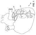
図1は、人間の心臓50を、ある程度、様式化した図である。心臓50は、その全てが閉塞の影響を受けやすい、複数の冠状動脈52を含む。特定の生理学的な状況において、かつ、十分な時間が与えられている場合、いくつかの閉塞は、完全閉塞36等、完全または全面的であり得る。本明細書で使用されているように、完全閉塞および全面閉塞という用語は、閉塞の古さにはいくらかの幅がある、同じまたは同様の閉塞の度合いを指すことを意図している。概して、完全閉塞は、断面領域において90パーセント以上の機能が閉塞されている血管腔を指しており、その内部には血流がほとんどあるいは全く流れていないと考えられ、その内部を従来のガイドワイヤが通過することは困難または不可能である。さらに、概して、完全閉塞から時間が経つほど、閉塞性物質はより組織化(organized)し、より繊維状になると共に石灰化する。ある確立された臨床的な定義によると、完全閉塞は、症状が始まってから2週間を過ぎる場合に、慢性的であると理解される。
FIG. 1 shows a
図2は、前の図に示された心臓50の部分をさらに説明する、拡大図である。図2において、冠状動脈52内に完全閉塞36が示される。概して、動脈52の近接したセグメント32(つまり、完全閉塞36に近接した動脈52の一部)は、血管内デバイスを使用して進入が容易であってもよく、周囲の心筋に供給するための適度な血流を有する。動脈52の遠位セグメント34(つまり、完全閉塞36の末端の動脈部分52)は、介入(intervening)デバイスでは進入が容易ではなく、近接したセグメント32と比較して、大幅に血流量を低下させる。
FIG. 2 is an enlarged view further illustrating the portion of the
図3は、壁22を有する動脈20の斜視図である。図3において、3層構造を有する動脈20の壁22が示されている。壁22の最も外側の層は外膜24であり、壁22の最も内側の層は内膜26である。内膜26は、動脈20の真の内腔30を画定する。内膜26および外膜24の間を延伸する組織は、中間部分28と総称されてもよい。説明のために、内膜26、中間部分28および外膜24は、それぞれ、図3において、単一の均一層として示されている。しかしながら、人間の身体において、内膜および中間部分は、それぞれいくつかの副層を含む。内膜の最も外側の部分および中間部分の最も内側の部分の間の変化部分は、内膜下空間40と称されることがある。
FIG. 3 is a perspective view of an
図3を参照すると、内膜下空間40は、概して、真の内腔の中心に、その半径方向の中心を有する環状形状を有することが理解されよう。この発明を実施するための形態において記載されるデバイスおよび方法のいくつかは、血管の真の内腔に対する内膜下空間40の位置および形状を利用してもよい。例えば、本明細書中に記載された、いくつかの定位デバイスは、その空間内においてそれ自体を方向付けるように適合されてもよい。定位デバイスの方向付けが確立されると、定位デバイスは、真の内腔に対して再入力デバイスを方向付けるように使用されてもよい。
Referring to FIG. 3, it will be appreciated that the
図4は、前の図に示された動脈20の側面断面図である。図4において、定位デバイス100は、動脈20の外膜24および内膜26の間に配置されて示されている。定位デバイス100は、中央内腔104を画定する外壁128を有する遠位軸102を含む。定位デバイス100は、遠位軸102に結合される定位要素120を含む。
FIG. 4 is a side cross-sectional view of the
図4の実施形態において、定位要素120は、膨張可能部材126を含む。膨張可能部材126の上部は、例えば、第1の接触面190Aの遠位軸102に固定されてもよい。膨張可能部材126の底部は、例えば、第2の接触面190Bの遠位軸102に固定されてもよい。
In the embodiment of FIG. 4, the
定位要素120は、第1の部分106および第2の部分108を含む。定位要素120の第1の部分106は、遠位軸102から離れた第1の方向に延伸する。定位要素120の第2の部分108は、第1の方向の略反対の第2の方向に、遠位軸102から離れて延伸する。
The
遠位軸102は、第1のアパーチャ130および第2のアパーチャ132を画定する。第1のアパーチャ130は、遠位軸102を通って、第3の方向に延伸する。第2のアパーチャ132は、第3の方向の略反対である第4の方向に、遠位軸102を通って延伸する。第1のアパーチャ130および第2のアパーチャ132は、概して、接平面TPと直角に方向付けられる。図4において、接平面TPは、内膜下空間40の接線となる。
The
定位要素120の膨張可能部材126が、動脈20の外膜24および内膜26の間で膨張する場合、定位デバイス100は、第1のアパーチャ130または第2のアパーチャ132のいずれか一方が、動脈の真の内腔に対して開くように、それ自体を動脈20内に方向付ける。図4の実施形態において、定位デバイス100は、第1のアパーチャ130が動脈20の内膜26に対して開き、第2のアパーチャ132が外膜24に対して開くように、配置されている。図4において、再入力デバイス80は、第1のアパーチャ130および内膜26を通って延伸して示されている。再入力デバイス80の遠位端は、血管20の真の内腔30に配置される。
When the
膨張可能部材126が膨張する場合、第1のアパーチャ130および第2のアパーチャ132が向き得る方向の数が低減する。これは、自由度で概念化され得る。定位要素120の膨張可能部材126が膨張する場合、アパーチャが向き得る方向の数は、360の自由度から180度離れた2の自由度まで低減する。定位デバイス100および再入力デバイス80は、閉塞によって分離された近接したセグメントおよび遠位セグメントの間の流体連通を確立するために使用してもよい。図5〜図13を参照し、例示的な方法について説明する。
When the
図5は、その真の内腔30を塞いでいる閉塞36を有する動脈20の縦方向の断面図である。閉塞36は、真の内腔30を、近接したセグメント32および遠位セグメント34に分割する。図5において、ガイドワイヤ60の遠位部は、真の内腔30の近接したセグメント32に延伸して示される。本文書に記載される方法は、血管内閉塞に近接する位置にガイドワイヤを前進させるステップを含んでもよい。本文書に記載される例示的な方法は、さらに、閉塞36および壁22の外膜24の間にガイドワイヤ60を前進させるステップを含んでもよい。しかしながら、いくつかの場合において、閉塞および血管の性質のために、ガイドワイヤが閉塞を越えて前進する可能性は少ない。この場合、ガイドワイヤは、閉塞36に近接する位置に、さらなる血管内デバイスを導くように使用されてもよい。
FIG. 5 is a longitudinal cross-sectional view of
図6は、前の図に示された動脈20のさらなる断面図である。図6の実施形態において、横断デバイス70は、横断デバイス70の遠位部が、真の内腔30の近接したセグメント32に配置されるように、ガイドワイヤ60上を前進している。図6の横断デバイス70は、軸72の遠位端に固定された先端74を含む。横断デバイス70は、近接したセグメント32および遠位セグメント34の間の経路を確立するための方法と共に使用されてもよい。本文書に記載される方法は、ガイドワイヤ上で横断デバイスを前進させるステップを含んでもよい。
FIG. 6 is a further cross-sectional view of the
本開示に従ういくつかの有用な方法において、横断デバイス70は、その縦軸を中心に回転してもよく、また、同時に、その縦軸に対して平行な方向に移動させてもよい。この場合、横断デバイス70の回転は、横断デバイス70の軸方向の前進への抵抗を低減することができる。これらの方法は、摩擦運動係数が、所与の摩擦接触面について、通常、静的な摩擦係数未満であるという事実を利用する。横断デバイス70の回転により、横断デバイスおよび周囲組織の間の接触面における摩擦係数が、摩擦運動係数になり、静的な摩擦係数になるのではないことが確実になる。
In some useful methods in accordance with the present disclosure, the crossing
図7は、前の図に示された横断デバイス70を含むアセンブリを示す平面図である。図7の実施形態において、ハンドルアセンブリ150は、横断デバイス70に結合される。図7において、ハンドルアセンブリ150は、横断デバイス70の軸152の近接した部分の周りに配置されて示されている。図7において、ハンドルアセンブリ150の一部は、左手LHの親指および人差し指の間に配置される。ハンドルアセンブリ150の第2の部分は、右手RHの親指および人差し指の間に配置される。図7を参照すると、ハンドルアセンブリ150は、医師の右手および左手の親指および人差し指を受けるのに十分長いことが理解される。この場合、医師は、ハンドルアセンブリ150を回転させるために、両手を使用できる。
FIG. 7 is a plan view showing an assembly including the
片方の手の親指および人差し指の間でハンドルアセンブリ150を回転させることによって、横断デバイス70を回転できる。さらに、図7に示されるように、ハンドルアセンブリ150を回転させるために、両手を使用してもよい。いくつかの有用な方法において、横断デバイス70を回転し、同時に軸方向に前進させることができる。
The crossing
本開示に従ういくつかの有用な方法において、横断デバイス70は、一分あたり約2回転から一分あたり約200回転の間の速度の回転速度で回転させる。本開示に従ういくつかの特に有用な方法において、横断デバイス70は、1分当たり約50回転および1分当たり約150回転の間の回転速度で回転させる。
In some useful methods in accordance with the present disclosure, the crossing
横断デバイス70は、図7に示されるように、手で回転させてもよい。さらに、機械的デバイス(例:電気モータ)を、横断デバイス70を回転させるために使用してもよいことが考えられる。横断デバイス70の回転により、横断デバイスおよび周囲の組織の間の接触面における摩擦係数は、摩擦運動係数となり、静的な摩擦係数とはならないことが確実になる。
The crossing
図8は、動脈20のさらなる縦方向の断面図である。図8の実施形態において、横断デバイス70の遠位端は、先端74が閉塞36に隣接するように、遠位方向に前進させられている。図8を参照すると、先端74は内膜26を越えて通過しており、動脈20の閉塞36および外膜24の間に配置されることが理解されよう。本文書に記載されるいくつかの方法は、閉塞および動脈の外膜の間に横断デバイスを前進させるステップを含んでもよい。
FIG. 8 is a further longitudinal cross-sectional view of the
図9は、前の図に示された動脈20および横断デバイス70のさらなる図である。図9の実施形態において、横断デバイス70の遠位端は、閉塞36を越えて、軸方向に前進させられている。本明細書に記載される方法は、閉塞を越えて横断デバイスを前進させるステップを含んでもよい。図9の実施形態において、横断デバイスは、閉塞36および壁22の外膜24の間を前進することにより、閉塞36を横断している。
FIG. 9 is a further view of
閉塞を横断する他の方法は、本開示の趣旨および範囲内であることを理解されたい。例えば、横断デバイス70は、真の内腔30内の位置を維持しながら、閉塞36を通って通過してもよい。図9において、横断デバイス70の先端74が、動脈20の内膜26および外膜24の間に存在して示されている。先端74が内膜26および外膜24の間を軸方向に移動する際に、先端74は、動脈20の壁22を形成する層に、鈍的切開を生じさせてもよい。あるいは、先端74は、閉塞36を含む物質に、鈍的切開を生じさせてもよい。
It should be understood that other ways of traversing the occlusion are within the spirit and scope of the present disclosure. For example, the crossing
図9の実施形態において、横断デバイス70の先端74は、内膜26および外膜24の間に配置される。この場合、近接したセグメント32および遠位セグメント34の間の流体連通は、内膜26を通って開口を作成することにより、実行されてもよい。こうした開口は、例えば、脈再入力デバイス、および管内膜26への再入力デバイスの前進を方向付ける定位デバイスを使用して、作成されてもよい。
In the embodiment of FIG. 9, the
図10は、前の図に示された動脈20のさらなる図である。図10の実施形態において、横断デバイス70は、動脈20の真の内腔30から引き出されている。図10を参照すると、ガイドワイヤ60は、横断デバイス70によって以前占められていた位置に留まっていることが理解されよう。
FIG. 10 is a further view of the
図10に示されるガイドワイヤ60の位置は、横断デバイス70を使用して実行されてもよい。ガイドワイヤ60は、例えば、まず、前の図で示された位置に横断デバイス70を配置し、次に、ガイドワイヤ60を、横断デバイス70の軸72で画定される内腔122を通って前進させることにより、配置されてもよい。あるいは、ガイドワイヤ60は、横断デバイス70が閉塞36を越えて前進させる間、内腔122内に配置されてもよい。
The position of the
ガイドワイヤ60が図10に示される位置にあるため、ガイドワイヤ60は、閉塞36および外膜24の間に他のデバイスを方向付けるように使用されてもよい。例えば、カテーテルの遠位端が閉塞および外膜の間を延伸するまで、カテーテルをガイドワイヤ60上で前進させてもよい。その位置に到達後、カテーテルは、カテーテルの周囲の組織を拡張するように使用されてもよい。組織を拡張するように使用可能なカテーテルの例には、膨張可能部材カテーテルおよびアテローム切除術カテーテルを含む。
Because the
図11は、前の図に示された動脈20およびガイドワイヤ60のさらなる図である。図11の実施形態において、定位デバイス100は、ガイドワイヤ60上を前進させられている。定位デバイス100は、中央内腔104を画定する外壁128を含む遠位軸102を含む。第1のアパーチャ130および第2のアパーチャ132は、さらに、外壁128によって画定される。図11の実施形態において、第1のアパーチャ130および第2のアパーチャ132は、共に、中央内腔104と流体連通する。
FIG. 11 is a further view of the
図11の実施形態において、定位デバイス100は、第1のアパーチャ130が、動脈20の内膜26に向かって開き、第2のアパーチャ132が、外膜24に向かって開くように、配置されている。図11の実施形態において、第1のアパーチャ130および第2のアパーチャ132は、縦方向に相互に分離している。定位デバイス100は、第1のアパーチャ130および第2のアパーチャ132の間に配置される第1の放射線非透過性マーカを含む。定位デバイス100の第2の放射線非透過性マーカは、第2のアパーチャ132から離れて配置されている。
In the embodiment of FIG. 11, the
図12は、前の図に示された動脈20および定位デバイス100のさらなる図である。図12の実施形態において、ガイドワイヤ60は、定位デバイス100を図12に示される位置に置いた状態で、引き出されている。図12を参照すると、定位デバイス100は、閉塞36を超えて延伸することが理解される。図12において、真の内腔30を塞いでいる閉塞36が示されている。閉塞36は、真の内腔30を、近接したセグメント32および遠位セグメント34に分割する。本明細書に記載されるいくつかの実施形態に従う定位デバイスが、動脈の外膜および内膜の間を前進させられる場合、真の内腔30の方に再入力デバイスを方向付けるように、定位デバイスを使用してもよい。近接したセグメント32および遠位セグメント34の間の流体連通は、再入力デバイスによって真の内腔に再入力させることで行われてもよい。
FIG. 12 is a further view of the
図13は、前の図に示された動脈20および定位デバイス100のさらなる図である。図13の実施形態において、再入力デバイス80は、定位デバイス100の中央内腔104内に前進させられている。再入力デバイス80の遠位端132は、第1のアパーチャ130を通って前進させられており、真の内腔30に存在するものとして示されている。
FIG. 13 is a further view of the
図13に示されるように再入力デバイス80が配置された後、定位デバイス100は、再入力デバイス80を、図13に示された位置に留めたまま、引き出してもよい。次いで、膨張可能部材の血管形成カテーテルおよびアテローム切除術カテーテル等のデバイスを、再入力デバイス80上で前進させてもよい。このように、真の内腔30の近接したセグメント32および真の内腔30の遠位セグメント34の間の血流経路を確立するために、再入力デバイス80と共にこれらのデバイスを使用してもよい。この経路は、閉塞36の周囲を血液が流れることを可能にする。
After the
図14は、前の図に示された定位デバイス100の拡大断面図である。定位デバイス100は、中央内腔104を画定する外壁128を含む遠位軸102を含む。外壁128は、共に、中央内腔104と流体連通する第1のアパーチャ130および第2のアパーチャ132を画定する。図14の実施形態において、第1のアパーチャ130は、図14において第1の矢印AAで表される第1の方向に、中央内腔104から離れて延伸する。第2のアパーチャ132は、図14において第2の矢印ABで示される第2の方向に、中央内腔104から離れて延伸する。図14において、第1の矢印AAおよび第2の矢印ABは、略反対方向に延伸する。図14において、第1の矢印AAおよび第2の矢印ABは、互いに約180度離れて方向付けられる。
FIG. 14 is an enlarged cross-sectional view of the
図14の実施形態において、第1のアパーチャ130および第2のアパーチャ132は、互いに縦方向に分離している。定位デバイス100は、第1のアパーチャ130および第2のアパーチャ132の間に配置される第1の放射線非透過性マーカ134を含む。定位デバイス100の第2の放射線非透過性マーカ134Bは、第2のアパーチャ132とは離れて配置される。
In the embodiment of FIG. 14, the
再入力デバイス80は、定位デバイス100の中央内腔104に配置される。図14Aの実施形態において、第1の放射線非透過性マーカ134A、第2の放射線非透過性マーカ134Bおよび再入力デバイス80は、放射線非透過性物質を含む。その構成物質の放射線非透過性の性質のために、第1の放射線非透過性マーカ134A、第2の放射線非透過性マーカ134B、および再入力デバイス80は、全て、X線透視手順中にX線透視ディスプレイで視覚可能となる。X線透視ディスプレイ上のこれらの放射線非透過性の要素の相対的な位置は、定位デバイス100内の選択されたアパーチャによって、再入力デバイス80の遠位端を方向付けるように使用可能である。
The
図15は、前の図に示された定位デバイス100を示す様式化された平面図である。図15において、再入力デバイス80の遠位部は、第1のアパーチャ130を通って延伸して示されている。第1のアパーチャ130および第2のアパーチャ132は、共に、定位デバイス100の中央内腔104と流体連通する。定位デバイス100は、第1のアパーチャ130および第2のアパーチャ132の間に配置された第1の放射線非透過性マーカ134を含む。定位デバイス100の第2の放射線非透過性マーカ134Bは、第2のアパーチャ132から離れて配置されている。
FIG. 15 is a stylized plan view showing the
定位デバイス100は、遠位軸102に固定された定位要素120を含む。定位要素120は、膨張可能部材126を含む。定位要素120の膨張可能部材126が、血管の外膜および内膜の間で膨張する場合、定位デバイス100は、第1のアパーチャ130または第2のアパーチャ132のいずれか一方が、動脈の真の内腔に向かって開くように、それ自体を血管内に方向付ける。医師は、例えば、本明細書に記載されているX線透視方法を使用して、真の内腔に向かうアパーチャ開口を選択してもよい。次いで、医師は、選択したアパーチャを通って、再入力デバイス80の遠位端を挿入してもよい。
The
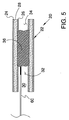
図16は、定位デバイス200の斜視図である。定位デバイス200は、遠位軸202、近接した軸92、および遠位軸202ならびに近接した軸92の間を延伸する中間軸82を含む。定位デバイス200は、遠位軸202に結合された定位要素220を含む。図21の実施形態において、定位要素220は、遠位軸202に固定された膨張可能部材226を含む。膨張可能部材226は、例えば、近接したウェスト246A、遠位ウェスト246B、膨張可能部材の上部226、および膨張可能部材の底部で、遠位軸202に固定されてもよい。
FIG. 16 is a perspective view of the
定位要素220は、第1の部分206および第2の部分208を含む。定位要素220の第1の部分206は、遠位軸202から離れた第1の方向に延伸する。定位要素220の第2の部分208は、第1の方向の略反対である第2の方向に、遠位軸202から離れて延伸する。
The
ハブ236が、近接した軸92の近接した端に固定される。ハブ236は、近接したポート238を含む。近接したポート238は、遠位軸202、中間軸82、および近接した軸92によって画定された膨張内腔を介して、膨張可能部材226の内部と流体連通する。膨張可能部材226は、近接したポート238へ、膨張媒体を注入することにより、膨張させてもよい。いくつかの応用に適し得る膨張中間部分の例は、生理食塩水、二酸化炭素、または窒素を含む。いくつかの有用な実施形態において、膨張可能部材226、遠位軸202、中間軸82、および近接した軸92は、熱可塑性物質を含む。いくつかの応用に適し得る熱可塑性物質の例は、ナイロン、Pebax(ポリエーテルブロックアミド共重合体)、またはP.E.T(ポリエチレンテレフタレート)である。
定位要素220の第1の側に第1のアパーチャ230が配置される。定位要素220の膨張可能部材226が血管の外膜および内膜の間で膨張する場合、定位デバイス200は、第1のアパーチャ230が動脈の真の内腔に向かって開くように、または、動脈の真の内腔から180度離れて開くように、それ自体を血管内に方向付ける。第2のアパーチャは、定位要素220の第2の側に配置される。第2のアパーチャは、図16において外部から見えない。第1のアパーチャ230は、定位要素220の第1の側に配置され、第2のアパーチャは、第1の側の略反対である定位要素の第2の側に配置される。
A
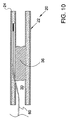
図17は、さらなる例示的な定位デバイス300を示す平面図である。図17の定位デバイス300は、遠位軸302に結合された定位要素320を含む。図17の実施形態において、定位要素320は、第1の膨張可能部材322および第2の膨張可能部材324を含む。図17の実施形態において、第1の膨張可能部材322および第2の膨張可能部材324は、共に、遠位軸302の外壁328の押し出し部分から形成される。外壁328は、第1のアパーチャ330および第2のアパーチャ332を画定する。図17を参照すると、第1のアパーチャ330および第2のアパーチャ332は、共に、第1の膨張可能部材322および第2の膨張可能部材324の間に配置されることが理解されよう。
FIG. 17 is a plan view illustrating a further
図18は、前の図に示される定位デバイス300の一部分340を示す様式化された斜視図である。一部分340は、前の図に示された切り取り面A−Aおよび切り取り面B−Bに沿って、定位デバイス300を切り取ることで作成される。
FIG. 18 is a stylized perspective view showing a
定位デバイス300は、遠位軸302に結合された定位要素320を含む。定位要素320は、第1の膨張可能部材322および第2の膨張可能部材324を含む。定位要素320の第1の膨張可能部材322は、遠位軸302から離れて第1の方向に延伸する。定位要素320の第2の膨張可能部材324は、第1の方向の略反対である第2の方向に、遠位軸302から離れて延伸する。
The
図18を参照すると、第1の膨張可能部材322は、ODと表示された矢印で表される第1の方向に、外壁328から離れて延伸することが理解されよう。引き続き、図18を参照すると、第2の膨張可能部材324は、第1の方向とは略反対である第2の方向に、遠位軸302から離れて延伸する。図18において、第2の方向は、SDと表示された矢印で表される。
Referring to FIG. 18, it will be appreciated that the first
図18を参照すると、遠位軸302の外壁328は、第1のアパーチャ330および第2のアパーチャ332を画定することが理解されよう。第1のアパーチャ330は、TDと表示された矢印で表された第3の方向に、中央内腔304から離れて延伸する。引き続き、図18を参照すると、第2のアパーチャ332は、第3の方向と略反対である第4の方向に、中央内腔304から延伸する。図18において、第4の方向は、FDと表示された矢印で表される。
Referring to FIG. 18, it will be appreciated that the
図18を参照すると、第1のアパーチャ330および第2のアパーチャ332は、共に、第1の膨張可能部材322および第2の膨張可能部材324の間に配置されることが理解されよう。第1のアパーチャ330および第2のアパーチャ332は、共に、遠位軸302によって画定された中央内腔304と流体連通する。第1のアパーチャ330および第2のアパーチャ332は、概して、定位要素320の第1の膨張可能部材322および第2の膨張可能部材324によって画定された面Pに対して直角に方向付けられる。
Referring to FIG. 18, it will be appreciated that the
図19は、前の図で示された定位デバイス300を示す様式化された断面図である。図19を参照すると、遠位軸302は、中央内腔304、第1の遊星内腔342、第2の遊星内腔344を画定することが理解されよう。これらの遊星内腔は、遠位軸302の外壁328によって、一部が画定される。外壁328は、さらに、第1のアパーチャ330および第2のアパーチャ332を画定する。第1のアパーチャ330および第2のアパーチャ332は、共に、中央内腔304と流体連通する。
FIG. 19 is a stylized cross-sectional view showing the
定位デバイス300は、第1の膨張可能部材322および第2の膨張可能部材324を含む定位要素320を含む。図19の実施形態において、第1の膨張可能部材322は、遠位軸302の外壁328の押し出し部分で形成される。第1の膨張可能部材322は、第1の遊星内腔342と流体連通する内部を画定する。図19の実施形態において、第1の膨張可能部材322および遠位軸302は、モノリシック構造である。図19に示されるように、第1の膨張可能部材322および遠位軸302の外壁328は、単一の物質で、継ぎ目なく形成される。図19を参照すると、第2の膨張可能部材324は、第2の遊星内腔344と流体連通する内部を画定することが理解される。図19の実施形態において、第2の膨張可能部材324は、遠位軸302の外壁328の押し出し部分を含む。
The
モノリシックな管から定位要素を作成することの1つの考えられる利点は、定位要素およびカテーテル軸の間の固定点が不要になるため、処理ステップおよび製造コストを低減できるという点である。別の考えられる利点に、重複する物質の領域を排除することにより、カテーテルの遠位直径を小さくし得る、定位要素およびカテーテル軸の間の固定点の削減がある。別の考えられる利点として、定位要素およびカテーテル軸の間の固定点(例えば、熱または接着による結合)を排除することによる、考えられる不具合点の削減を含み得る。 One possible advantage of creating a stereotactic element from a monolithic tube is that it eliminates the need for a fixed point between the stereotactic element and the catheter shaft, thereby reducing processing steps and manufacturing costs. Another possible advantage is the reduction of the anchoring point between the stereotactic element and the catheter shaft, which can reduce the distal diameter of the catheter by eliminating the area of overlapping material. Another possible advantage may include a reduction in possible defects by eliminating a fixed point (eg, a thermal or adhesive bond) between the stereotactic element and the catheter shaft.
定位要素320の第1の膨張可能部材322は、遠位軸302から離れて第1の方向に延伸する。定位要素320の第2の膨張可能部材324は、第1の方向とは略反対である第2の方向に、遠位軸302から離れて延伸する。
First
図19の実施形態において、定位要素320は、設定された形状を想定する。さらに、図19の実施形態において、第1の膨張可能部材322および第2の膨張可能部材324は、共に、略膨張状態である。図19を参照すると、第1の膨張可能部材322および第2の膨張可能部材324は、平面Pを画定することが理解されよう。引き続き図19を参照すると、定位要素320は、第1の幅WAおよび第1の厚さTAを有することが理解されよう。図19の実施形態において、定位要素320が設定された形状を想定する場合、第1の幅WAは第1の厚さTAよりも大きい。
In the embodiment of FIG. 19, the
いくつかの有用な実施形態において、第1の幅WAの第1の厚さTAに対する比率は、定位要素320が設定された形状を想定している場合に、1よりも大きい。いくつかの特に有用な実施形態において、第1の幅WAの第1の厚さTAに対する比率は、定位要素320が設定された形状を想定している場合に、約2よりも大きい。いくつかの特に有用な実施形態において、第1の幅WAの第1の厚さTAに対する比率は、定位要素320が設定された形状を想定している場合に、約3よりも大きい。
In some useful embodiments, the ratio of the first width WA to the first thickness TA is greater than 1 when assuming a shape with the
図20は、前の図に示された定位デバイス300を示す、さらなる様式化された断面図である。図20の実施形態において、定位要素320は略崩壊形状を想定しており、膨張可能部材は略収縮状態である。膨張可能部材が収縮している場合、定位要素320は、種々の崩壊および/または折り畳み形状を想定してもよい。図20の実施形態において、定位要素320は第2の幅WBを有する。
FIG. 20 is a further stylized cross-sectional view showing the
図20の点線で、定位要素320の設定された形状が示される。図20を参照すると、定位要素320が設定された形状を想定している場合に、定位要素320は、第2の幅WBよりも大きい第1の幅WAを有することが理解されよう。
A set shape of the
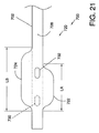
図21は、さらなる例示的な定位デバイス700を示す平面図である。図21の定位デバイス700は、遠位軸702に結合された定位要素720を含む。図21の実施形態において、定位要素720は、第1の膨張可能部材722および第2の膨張可能部材724を含む。図21の実施形態において、第1の膨張可能部材722および第2の膨張可能部材724は、共に、遠位軸702の外壁728の押し出し部分から形成される。外壁728は、第1のアパーチャ730および第2のアパーチャ732を画定する。図21を参照すると、第1のアパーチャ730および第2のアパーチャ732は、共に、第1の膨張可能部材722および第2の膨張可能部材724の間に配置されることが理解されよう。
FIG. 21 is a plan view illustrating a further
図21を参照すると、第1の膨張可能部材722は第1の長さLAを有し、第2の膨張可能部材724は第2の長さLBを有することが理解されよう。図21の実施形態において、第2の長さLBは、第1の長さLAよりも大きい。有用な一方法において、第1の膨張可能部材722および第2の膨張可能部材724は、共に、放射線非透過性の膨張媒体によって膨張する。この場合、医師は、X線透視ディスプレイにおいて第1の膨張可能部材722および第2の膨張可能部材724を観察することにより、定位デバイス700の方向付けを決定するために、X線透視視覚化技術を使用してもよい。
Referring to FIG. 21, it will be appreciated that the first
上記から、本発明は、例示的な非制限的実施形態において、慢性的な完全閉塞の治療のためのデバイスおよび方法を提供することが、当業者には明らかであろう。さらに、当業者は、本発明が、本明細書に記載および検討された特定の実施形態以外の種々の形態で明らかにされ得ることを認識されよう。従って、添付の特許請求の範囲に記載されるように、本発明の範囲および趣旨から逸脱せずに、形式および詳細の逸脱を実行し得る。 From the foregoing, it will be apparent to those skilled in the art that the present invention, in an exemplary non-limiting embodiment, provides devices and methods for the treatment of chronic total occlusion. Further, those skilled in the art will recognize that the present invention may be manifested in a variety of forms other than the specific embodiments described and discussed herein. Accordingly, departures in form and detail may be made without departing from the scope and spirit of the invention as set forth in the appended claims.
Claims (30)
前記第1のアパーチャ及び前記第2のアパーチャは、共に、前記血管内デバイスの軸方向に延びる中央内腔と流体連通しており、
前記第1のアパーチャ及び第2のアパーチャは軸方向に沿って互いに離間して配置され、第1のアパーチャが開口する方向と第2のアパーチャが開口する方向とは互いに180度離れて配置され、
前記第1の膨張可能部材および前記第2の膨張可能部材は、膨張する前に折り畳まれた形状を有する、装置。 An apparatus for facilitating treatment through a vessel wall defining a vessel lumen including an occlusion within a vessel lumen, the device comprising an intravascular device having a distal portion, the distal portion being a first An aperture and a second aperture; a first inflatable member and a second inflatable member;
Said first aperture and said second aperture, both Ri Contact through central lumen in fluid communication with and extending in the axial direction of the intravascular device,
The first aperture and the second aperture are arranged apart from each other along the axial direction, and the direction in which the first aperture opens and the direction in which the second aperture opens are arranged 180 degrees apart from each other,
The device wherein the first inflatable member and the second inflatable member have a folded shape prior to inflation.
前記第1の膨張可能部材および前記第2の膨張可能部材が略収縮した状態である場合に、前記血管内デバイスは、第2の幅を有する、請求項7に記載の装置。 Before the winding tube device, when the first inflatable member and the second expandable member is in a state of being substantially expanded, it has a first width and a first thickness,
8. The apparatus of claim 7, wherein the intravascular device has a second width when the first inflatable member and the second inflatable member are in a substantially contracted state.
前記第1および第2の膨張可能部材は、それぞれ、前記第1および第2の遊星内腔と流体連通する、請求項7に記載の装置。 The axis defines first and second planetary lumens ;
8. The apparatus of claim 7, wherein the first and second inflatable members are in fluid communication with the first and second planetary lumens, respectively.
遠位部を有する定位デバイスであって、前記遠位部は、第2のアパーチャより近位に配置された第1のアパーチャと、前記第1のアパーチャの端部に配置された少なくとも1つの放射線非透過性マーカと、第1の膨張可能部材および第2の膨張可能部材を含む定位要素と、を含む定位デバイスを備え、
前記第1の膨張可能部材および前記第2の膨張可能部材は、膨張する前に折り畳まれた形状を有し、
前記第1のアパーチャ及び前記第2のアパーチャは、共に、前記定位デバイスの軸方向に延びる中央内腔と流体連通しており、
前記第1のアパーチャおよび第2のアパーチャは軸方向に沿って互いに離間して配置され、第1のアパーチャが開口する方向と第2のアパーチャが開口する方向とは互いに180度離れて配置され、
前記第1のアパーチャおよび前記第2のアパーチャはそれぞれ前記第1の膨張可能部材および前記第2の膨張可能部材の間に配置されている、装置。 A device for facilitating treatment through a vessel wall defining a vessel lumen including an occlusion within the vessel lumen, said device comprising:
A stereotactic device having a distal portion, the distal portion comprising a first aperture disposed proximal to a second aperture and at least one radiation disposed at an end of the first aperture A positioning device comprising a non-permeable marker and a positioning element including a first expandable member and a second expandable member;
The first inflatable member and the second inflatable member have a folded shape prior to inflation;
Said first aperture and said second aperture, both Ri Contact through central lumen in fluid communication with and extending in the axial direction of the localization device,
The first aperture and the second aperture are arranged apart from each other along the axial direction, and the direction in which the first aperture opens and the direction in which the second aperture opens are arranged 180 degrees apart from each other,
The apparatus, wherein the first aperture and the second aperture are disposed between the first inflatable member and the second inflatable member, respectively.
前記再入力デバイスは、本体と遠位端とを有する、請求項17に記載の装置。 A re-input device that is rotatable within the stereotactic device and configured to advance through at least one of the first and second apertures;
The apparatus of claim 17 , wherein the re-entry device has a body and a distal end.
Applications Claiming Priority (3)
| Application Number | Priority Date | Filing Date | Title |
|---|---|---|---|
| US12/222,737 | 2008-08-14 | ||
| US12/222,737 US9060802B2 (en) | 2006-11-21 | 2008-08-14 | Endovascular devices and methods for exploiting intramural space |
| PCT/US2009/004634 WO2010019241A1 (en) | 2008-08-14 | 2009-08-13 | Endovascular devices and methods for exploiting intramural space |
Publications (3)
| Publication Number | Publication Date |
|---|---|
| JP2011530380A JP2011530380A (en) | 2011-12-22 |
| JP2011530380A5 JP2011530380A5 (en) | 2012-09-27 |
| JP5635508B2 true JP5635508B2 (en) | 2014-12-03 |
Family
ID=41319476
Family Applications (1)
| Application Number | Title | Priority Date | Filing Date |
|---|---|---|---|
| JP2011522995A Expired - Fee Related JP5635508B2 (en) | 2008-08-14 | 2009-08-13 | Device for facilitating treatment through vessel wall |
Country Status (4)
| Country | Link |
|---|---|
| US (3) | US9060802B2 (en) |
| EP (4) | EP2349031B1 (en) |
| JP (1) | JP5635508B2 (en) |
| WO (1) | WO2010019241A1 (en) |
Families Citing this family (50)
| Publication number | Priority date | Publication date | Assignee | Title |
|---|---|---|---|---|
| US7918870B2 (en) | 2005-09-12 | 2011-04-05 | Bridgepoint Medical, Inc. | Endovascular devices and methods |
| US8083727B2 (en) | 2005-09-12 | 2011-12-27 | Bridgepoint Medical, Inc. | Endovascular devices and methods for exploiting intramural space |
| US11020141B2 (en) | 2005-09-12 | 2021-06-01 | Bridgepoint Medical, Inc. | Endovascular devices and methods |
| JP5586147B2 (en) * | 2005-09-12 | 2014-09-10 | ブリッジポイント、メディカル、インコーポレイテッド | Intravascular device for utilizing the space in the wall |
| US8025655B2 (en) | 2005-09-12 | 2011-09-27 | Bridgepoint Medical, Inc. | Endovascular devices and methods |
| US10888354B2 (en) * | 2006-11-21 | 2021-01-12 | Bridgepoint Medical, Inc. | Endovascular devices and methods for exploiting intramural space |
| US11298511B2 (en) | 2006-11-21 | 2022-04-12 | Bridgepoint Medical, Inc. | Endovascular devices and methods for exploiting intramural space |
| US9060802B2 (en) | 2006-11-21 | 2015-06-23 | Bridgepoint Medical, Inc. | Endovascular devices and methods for exploiting intramural space |
| WO2008120209A1 (en) | 2007-03-29 | 2008-10-09 | Dan Rottenberg | Lumen reentry devices and methods |
| JP5453586B2 (en) | 2007-10-22 | 2014-03-26 | ブリッジポイント、メディカル、インコーポレイテッド | Device and method for traversing a chronic total occlusion |
| EP3251719B1 (en) * | 2008-02-05 | 2020-10-21 | Bridgepoint Medical, Inc. | Crossing occlusions in blood vessels |
| US8337425B2 (en) | 2008-02-05 | 2012-12-25 | Bridgepoint Medical, Inc. | Endovascular device with a tissue piercing distal probe and associated methods |
| EP4011305A1 (en) | 2008-04-28 | 2022-06-15 | Bridgepoint Medical, Inc. | Apparatus for crossing occlusions in blood vessels |
| WO2011025855A2 (en) | 2009-08-28 | 2011-03-03 | Si Therapies Ltd. | Inverted balloon neck on catheter |
| US8932315B2 (en) | 2010-10-18 | 2015-01-13 | W. L. Gore & Associates, Inc. | Systems and methods for percutaneous occlusion crossing |
| US9814862B2 (en) | 2011-06-30 | 2017-11-14 | The Spectranetics Corporation | Reentry catheter and method thereof |
| US8998936B2 (en) | 2011-06-30 | 2015-04-07 | The Spectranetics Corporation | Reentry catheter and method thereof |
| US8956376B2 (en) | 2011-06-30 | 2015-02-17 | The Spectranetics Corporation | Reentry catheter and method thereof |
| EP2757984B1 (en) | 2011-09-19 | 2018-08-29 | Boston Scientific Scimed, Inc. | Subintimal re-entry catheter and retrograde recanalization |
| AU2012347644B2 (en) | 2011-12-09 | 2017-04-20 | Boston Scientific Scimed, Inc. | Subintimal recanalization with bio-absorbable stent |
| US10052462B2 (en) * | 2012-05-07 | 2018-08-21 | The Regents Of The University Of California | Upper esophageal sphincter dilator |
| US20130304108A1 (en) * | 2012-05-08 | 2013-11-14 | Daniel C. Weber | Systems and apparatus for treating blood vessels and related methods |
| JP6085674B2 (en) | 2012-05-24 | 2017-02-22 | ボストン サイエンティフィック サイムド,インコーポレイテッドBoston Scientific Scimed,Inc. | Subintimal re-entry device |
| WO2014012011A1 (en) | 2012-07-13 | 2014-01-16 | Boston Scientific Scimed, Inc. | Wire-guided recanalization system |
| EP2872209B1 (en) | 2012-07-13 | 2018-06-20 | Boston Scientific Scimed, Inc. | Subintimal reentry system |
| US9272121B2 (en) * | 2013-03-13 | 2016-03-01 | Invatec S.P.A. | Side lumen reentry catheters and related methods |
| JP6182660B2 (en) * | 2013-03-14 | 2017-08-16 | ボストン サイエンティフィック サイムド,インコーポレイテッドBoston Scientific Scimed,Inc. | Subintimal reentry catheter with shape-controlled balloon |
| US9878128B2 (en) | 2013-03-14 | 2018-01-30 | Boston Scientific Scimed, Inc. | Systems, apparatus and methods for treating blood vessels |
| US9623213B2 (en) * | 2013-03-15 | 2017-04-18 | Acclarent, Inc. | Uncinate process support for ethmoid infundibulum illumination |
| US9615959B2 (en) | 2013-03-15 | 2017-04-11 | Acclarent, Inc. | Uncinate process support for ethmoid infundibulum illumination |
| US9446222B2 (en) | 2014-03-05 | 2016-09-20 | Invatec S.P.A. | Catheter assemblies and methods for stabilizing a catheter assembly within a subintimal space |
| US10098650B2 (en) * | 2014-06-09 | 2018-10-16 | Boston Scientific Scimed, Inc. | Systems and methods for treating atherosclerotic plaque |
| US10391282B2 (en) | 2014-07-08 | 2019-08-27 | Teleflex Innovations S.À.R.L. | Guidewires and methods for percutaneous occlusion crossing |
| EP3169249B1 (en) * | 2014-07-15 | 2018-11-28 | Koninklijke Philips N.V. | Devices for intrahepatic shunts |
| US10456557B2 (en) * | 2014-08-14 | 2019-10-29 | Invatec S.P.A. | Occlusion bypassing apparatus with varying flexibility and methods for bypassing an occlusion in a blood vessel |
| GB201511595D0 (en) * | 2014-12-23 | 2015-08-19 | Whiteley Mark | Medical device for treating a vein |
| EP3270999B1 (en) | 2015-03-19 | 2022-12-07 | Boston Scientific Scimed, Inc. | Subintimal re-entry balloon catheter and method of forming thereof |
| US10172632B2 (en) | 2015-09-22 | 2019-01-08 | Medtronic Vascular, Inc. | Occlusion bypassing apparatus with a re-entry needle and a stabilization tube |
| US10327791B2 (en) | 2015-10-07 | 2019-06-25 | Medtronic Vascular, Inc. | Occlusion bypassing apparatus with a re-entry needle and a distal stabilization balloon |
| US10065018B2 (en) | 2016-03-16 | 2018-09-04 | Krishna Rocha-Singh | Apparatus and method for promoting angiogenesis in ischemic tissue |
| WO2018064402A1 (en) | 2016-09-30 | 2018-04-05 | Boston Scientific Scimed, Inc. | Pouch forming catheter |
| WO2019083757A1 (en) | 2017-10-26 | 2019-05-02 | Teleflex Innovations S.A.R.L. | Subintimal catheter device and assembly |
| US10058684B1 (en) | 2017-12-05 | 2018-08-28 | Justin Panian | Method and devices for passing a chronic total occlusion and re-entry into a true lumen |
| CN108378904B (en) * | 2018-01-11 | 2020-10-20 | 恩脉(上海)医疗科技有限公司 | Interventional therapy device |
| US11660420B2 (en) | 2018-09-17 | 2023-05-30 | Seigla Medical, Inc. | Catheters and related devices and methods of manufacture |
| US20200086089A1 (en) | 2018-09-17 | 2020-03-19 | Seigla Medical, Inc. | Systems, methods and apparatus for guiding and supporting catheters such as stent delivery catheters |
| US11547835B2 (en) | 2018-09-17 | 2023-01-10 | Seigla Medical, Inc. | Systems, methods and apparatus for guiding and supporting catheters and methods of manufacture |
| US11099537B2 (en) | 2019-06-28 | 2021-08-24 | Utilidata, Inc. | Utility grid control using a dynamic power flow model |
| US11575263B2 (en) | 2021-03-12 | 2023-02-07 | Utilidata, Inc. | Optimal power flow control via dynamic power flow modeling |
| EP4356152A1 (en) | 2021-06-15 | 2024-04-24 | Utilidata Inc. | Distance-to-fault power outage notification |
Family Cites Families (172)
| Publication number | Priority date | Publication date | Assignee | Title |
|---|---|---|---|---|
| US4020829A (en) * | 1975-10-23 | 1977-05-03 | Willson James K V | Spring guide wire with torque control for catheterization of blood vessels and method of using same |
| FR2392680A1 (en) | 1977-05-30 | 1978-12-29 | Rocco Francesco | BALLOON TYPE CATHETER |
| US4621636A (en) | 1979-07-23 | 1986-11-11 | Fogarty Thomas J | Endarterectomy method and apparatus |
| US4581017B1 (en) * | 1983-03-07 | 1994-05-17 | Bard Inc C R | Catheter systems |
| US4774949A (en) | 1983-06-14 | 1988-10-04 | Fogarty Thomas J | Deflector guiding catheter |
| US4819634A (en) | 1984-05-14 | 1989-04-11 | Surgical Systems & Instruments | Rotary-catheter for atherectomy system |
| US4979939A (en) | 1984-05-14 | 1990-12-25 | Surgical Systems & Instruments, Inc. | Atherectomy system with a guide wire |
| US4569347A (en) | 1984-05-30 | 1986-02-11 | Advanced Cardiovascular Systems, Inc. | Catheter introducing device, assembly and method |
| US4976689A (en) | 1984-09-18 | 1990-12-11 | Medtronic Versaflex, Inc. | Outer exchange catheter system |
| CA1293663C (en) | 1986-01-06 | 1991-12-31 | David Christopher Auth | Transluminal microdissection device |
| US4747821A (en) | 1986-10-22 | 1988-05-31 | Intravascular Surgical Instruments, Inc. | Catheter with high speed moving working head |
| US4762130A (en) | 1987-01-15 | 1988-08-09 | Thomas J. Fogarty | Catheter with corkscrew-like balloon |
| US5071406A (en) * | 1987-05-06 | 1991-12-10 | Jang G David | Limacon geometry balloon angioplasty catheter systems |
| US4958634A (en) * | 1987-05-06 | 1990-09-25 | Jang G David | Limacon geometry balloon angioplasty catheter systems and method of making same |
| US4878495A (en) * | 1987-05-15 | 1989-11-07 | Joseph Grayzel | Valvuloplasty device with satellite expansion means |
| US5372587A (en) | 1989-01-09 | 1994-12-13 | Pilot Cariovascular Systems, Inc. | Steerable medical device |
| US5201753A (en) | 1989-03-17 | 1993-04-13 | Merit Medical Systems, Inc. | Totally self-contained, digitally controlled, disposable syringe inflation system, and method for monitoring, displaying and recording balloon catheter inflation data |
| DE59010156D1 (en) | 1989-06-01 | 1996-04-04 | Schneider Europ Ag | Catheter arrangement with a guide wire and method for producing such a guide wire |
| US5571169A (en) | 1993-06-07 | 1996-11-05 | Endovascular Instruments, Inc. | Anti-stenotic method and product for occluded and partially occluded arteries |
| US5324263A (en) * | 1989-11-02 | 1994-06-28 | Danforth Biomedical, Inc. | Low profile high performance interventional catheters |
| WO1992008510A1 (en) | 1990-11-09 | 1992-05-29 | Boston Scientific Corporation | Guidewire for crossing occlusions in blood vessels |
| US5409453A (en) | 1992-08-12 | 1995-04-25 | Vidamed, Inc. | Steerable medical probe with stylets |
| US5275610A (en) | 1991-05-13 | 1994-01-04 | Cook Incorporated | Surgical retractors and method of use |
| US5193546A (en) | 1991-05-15 | 1993-03-16 | Alexander Shaknovich | Coronary intravascular ultrasound imaging method and apparatus |
| US5741429A (en) | 1991-09-05 | 1998-04-21 | Cardia Catheter Company | Flexible tubular device for use in medical applications |
| US5263493A (en) * | 1992-02-24 | 1993-11-23 | Boaz Avitall | Deflectable loop electrode array mapping and ablation catheter for cardiac chambers |
| US5555883A (en) * | 1992-02-24 | 1996-09-17 | Avitall; Boaz | Loop electrode array mapping and ablation catheter for cardiac chambers |
| US5505702A (en) * | 1992-04-09 | 1996-04-09 | Scimed Life Systems, Inc. | Balloon catheter for dilatation and perfusion |
| US6540764B1 (en) | 1992-06-02 | 2003-04-01 | General Surgical Innovations, Inc. | Apparatus and method for dissecting tissue layers |
| US5356418A (en) | 1992-10-28 | 1994-10-18 | Shturman Cardiology Systems, Inc. | Apparatus and method for rotational atherectomy |
| US5571122A (en) | 1992-11-09 | 1996-11-05 | Endovascular Instruments, Inc. | Unitary removal of plaque |
| US5643297A (en) | 1992-11-09 | 1997-07-01 | Endovascular Instruments, Inc. | Intra-artery obstruction clearing apparatus and methods |
| US5645529A (en) * | 1993-03-11 | 1997-07-08 | C. R. Bard, Inc. | Devices for selectively directing inflation devices |
| US5383856A (en) | 1993-03-19 | 1995-01-24 | Bersin; Robert M. | Helical spiral balloon catheter |
| GB9307572D0 (en) | 1993-04-13 | 1993-06-02 | Gould Derek A | Transintimal recanalisation device |
| US5415637A (en) | 1993-04-14 | 1995-05-16 | Advanced Cardiovascular Systems, Inc. | Temporary stenting catheter with drug delivery capabilities |
| US5501667A (en) * | 1994-03-15 | 1996-03-26 | Cordis Corporation | Perfusion balloon and method of use and manufacture |
| US5464395A (en) * | 1994-04-05 | 1995-11-07 | Faxon; David P. | Catheter for delivering therapeutic and/or diagnostic agents to the tissue surrounding a bodily passageway |
| US5603720A (en) | 1995-01-27 | 1997-02-18 | Kieturakis; Maciej J. | Surgical method for use with transluminal dilation catheter |
| US5534007A (en) | 1995-05-18 | 1996-07-09 | Scimed Life Systems, Inc. | Stent deployment catheter with collapsible sheath |
| US5944686A (en) | 1995-06-07 | 1999-08-31 | Hydrocision, Inc. | Instrument for creating a fluid jet |
| DE19535179A1 (en) | 1995-09-22 | 1997-03-27 | Wolf Gmbh Richard | Angled pipe and process for its manufacture |
| IL124037A (en) | 1995-10-13 | 2003-01-12 | Transvascular Inc | Device and system for interstitial transvascular intervention |
| US6726677B1 (en) | 1995-10-13 | 2004-04-27 | Transvascular, Inc. | Stabilized tissue penetrating catheters |
| US6375615B1 (en) | 1995-10-13 | 2002-04-23 | Transvascular, Inc. | Tissue penetrating catheters having integral imaging transducers and their methods of use |
| US6283951B1 (en) | 1996-10-11 | 2001-09-04 | Transvascular, Inc. | Systems and methods for delivering drugs to selected locations within the body |
| US6283983B1 (en) | 1995-10-13 | 2001-09-04 | Transvascular, Inc. | Percutaneous in-situ coronary bypass method and apparatus |
| US6302875B1 (en) | 1996-10-11 | 2001-10-16 | Transvascular, Inc. | Catheters and related devices for forming passageways between blood vessels or other anatomical structures |
| IL124038A (en) | 1995-10-13 | 2004-02-19 | Transvascular Inc | Apparatus for bypassing arterial obstructions and/or performing other transvascular procedures |
| US5843050A (en) | 1995-11-13 | 1998-12-01 | Micro Therapeutics, Inc. | Microcatheter |
| US5769871A (en) | 1995-11-17 | 1998-06-23 | Louisville Laboratories, Inc. | Embolectomy catheter |
| US6709444B1 (en) | 1996-02-02 | 2004-03-23 | Transvascular, Inc. | Methods for bypassing total or near-total obstructions in arteries or other anatomical conduits |
| WO1997027898A1 (en) | 1996-02-02 | 1997-08-07 | Transvascular, Inc. | Methods and apparatus for connecting openings formed in adjacent blood vessels or other anatomical structures |
| EP0879068A4 (en) | 1996-02-02 | 1999-04-21 | Transvascular Inc | Methods and apparatus for blocking flow through blood vessels |
| ATE247429T1 (en) | 1996-02-02 | 2003-09-15 | Transvascular Inc | SYSTEM FOR INTERSTITIAL TRANSVASCULAR SURGICAL PROCEDURES |
| US5695506A (en) | 1996-02-06 | 1997-12-09 | Devices For Vascular Intervention | Catheter device with a flexible housing |
| US6036707A (en) | 1996-03-07 | 2000-03-14 | Devices For Vascular Intervention | Catheter device having a selectively flexible housing |
| US5830224A (en) | 1996-03-15 | 1998-11-03 | Beth Israel Deaconess Medical Center | Catheter apparatus and methodology for generating a fistula on-demand between closely associated blood vessels at a pre-chosen anatomic site in-vivo |
| US5916194A (en) | 1996-05-24 | 1999-06-29 | Sarcos, Inc. | Catheter/guide wire steering apparatus and method |
| US5728133A (en) | 1996-07-09 | 1998-03-17 | Cardiologics, L.L.C. | Anchoring device and method for sealing percutaneous punctures in vessels |
| US5957900A (en) | 1996-07-10 | 1999-09-28 | Asahi Kogaku Kogyo Kabushiki Kaisha | Treatment accessory for endoscope |
| US5954713A (en) | 1996-07-12 | 1999-09-21 | Newman; Fredric A. | Endarterectomy surgical instruments and procedure |
| US6830577B2 (en) | 1996-07-26 | 2004-12-14 | Kensey Nash Corporation | System and method of use for treating occluded vessels and diseased tissue |
| US5779721A (en) | 1996-07-26 | 1998-07-14 | Kensey Nash Corporation | System and method of use for revascularizing stenotic bypass grafts and other blood vessels |
| US6652546B1 (en) | 1996-07-26 | 2003-11-25 | Kensey Nash Corporation | System and method of use for revascularizing stenotic bypass grafts and other occluded blood vessels |
| US6905505B2 (en) | 1996-07-26 | 2005-06-14 | Kensey Nash Corporation | System and method of use for agent delivery and revascularizing of grafts and vessels |
| US6059750A (en) | 1996-08-01 | 2000-05-09 | Thomas J. Fogarty | Minimally invasive direct cardiac massage device and method |
| US6447539B1 (en) | 1996-09-16 | 2002-09-10 | Transvascular, Inc. | Method and apparatus for treating ischemic heart disease by providing transvenous myocardial perfusion |
| US6186972B1 (en) | 1996-09-16 | 2001-02-13 | James A. Nelson | Methods and apparatus for treating ischemic heart disease by providing transvenous myocardial perfusion |
| US5655548A (en) | 1996-09-16 | 1997-08-12 | Circulation, Inc. | Method for treatment of ischemic heart disease by providing transvenous myocardial perfusion |
| US6379319B1 (en) | 1996-10-11 | 2002-04-30 | Transvascular, Inc. | Systems and methods for directing and snaring guidewires |
| US6432127B1 (en) | 1996-10-11 | 2002-08-13 | Transvascular, Inc. | Devices for forming and/or maintaining connections between adjacent anatomical conduits |
| EP1011458A2 (en) | 1996-11-08 | 2000-06-28 | Russell A. Houser | Percutaneous bypass graft and securing system |
| US6117064A (en) * | 1997-01-06 | 2000-09-12 | Apple; Marc G. | Catheter system |
| US6120516A (en) | 1997-02-28 | 2000-09-19 | Lumend, Inc. | Method for treating vascular occlusion |
| US6508825B1 (en) | 1997-02-28 | 2003-01-21 | Lumend, Inc. | Apparatus for treating vascular occlusions |
| US5968064A (en) | 1997-02-28 | 1999-10-19 | Lumend, Inc. | Catheter system for treating a vascular occlusion |
| US5741270A (en) | 1997-02-28 | 1998-04-21 | Lumend, Inc. | Manual actuator for a catheter system for treating a vascular occlusion |
| US6010449A (en) | 1997-02-28 | 2000-01-04 | Lumend, Inc. | Intravascular catheter system for treating a vascular occlusion |
| US6217549B1 (en) | 1997-02-28 | 2001-04-17 | Lumend, Inc. | Methods and apparatus for treating vascular occlusions |
| US6155264A (en) | 1997-03-06 | 2000-12-05 | Scimed Life Systems, Inc. | Percutaneous bypass by tunneling through vessel wall |
| CA2284720C (en) | 1997-04-11 | 2006-09-12 | Transvascular, Inc. | Methods and apparatus for transmyocardial direct coronary revascularization |
| US6071292A (en) | 1997-06-28 | 2000-06-06 | Transvascular, Inc. | Transluminal methods and devices for closing, forming attachments to, and/or forming anastomotic junctions in, luminal anatomical structures |
| DE29711559U1 (en) | 1997-07-02 | 1997-08-21 | Howmedica Gmbh | Elongated element for the transmission of forces |
| US6283940B1 (en) | 1997-08-29 | 2001-09-04 | S. Grant Mulholland | Catheter |
| US6071281A (en) * | 1998-05-05 | 2000-06-06 | Ep Technologies, Inc. | Surgical method and apparatus for positioning a diagnostic or therapeutic element within the body and remote power control unit for use with same |
| US6013055A (en) | 1997-11-13 | 2000-01-11 | Boston Scientific Corporation | Catheter balloon having selected folding characteristics |
| US6183432B1 (en) | 1997-11-13 | 2001-02-06 | Lumend, Inc. | Guidewire and catheter with rotating and reciprocating symmetrical or asymmetrical distal tip |
| US6330884B1 (en) | 1997-11-14 | 2001-12-18 | Transvascular, Inc. | Deformable scaffolding multicellular stent |
| US5935108A (en) | 1997-11-14 | 1999-08-10 | Reflow, Inc. | Recanalization apparatus and devices for use therein and method |
| US6217527B1 (en) | 1998-09-30 | 2001-04-17 | Lumend, Inc. | Methods and apparatus for crossing vascular occlusions |
| US20050171478A1 (en) | 1998-01-13 | 2005-08-04 | Selmon Matthew R. | Catheter system for crossing total occlusions in vasculature |
| US6231546B1 (en) | 1998-01-13 | 2001-05-15 | Lumend, Inc. | Methods and apparatus for crossing total occlusions in blood vessels |
| US6081738A (en) | 1998-01-15 | 2000-06-27 | Lumend, Inc. | Method and apparatus for the guided bypass of coronary occlusions |
| WO1999035977A1 (en) | 1998-01-16 | 1999-07-22 | Lumend, Inc. | Catheter apparatus for treating arterial occlusions |
| US6015405A (en) | 1998-01-20 | 2000-01-18 | Tricardia, L.L.C. | Device for forming holes in tissue |
| US6248121B1 (en) * | 1998-02-18 | 2001-06-19 | Cardio Medical Solutions, Inc. | Blood vessel occlusion device |
| US6824550B1 (en) | 2000-04-06 | 2004-11-30 | Norbon Medical, Inc. | Guidewire for crossing occlusions or stenosis |
| US6398798B2 (en) | 1998-02-28 | 2002-06-04 | Lumend, Inc. | Catheter system for treating a vascular occlusion |
| US6544230B1 (en) | 1998-03-31 | 2003-04-08 | Transvascular, Inc. | Catheters, systems and methods for percutaneous in situ arterio-venous bypass |
| US6561998B1 (en) | 1998-04-07 | 2003-05-13 | Transvascular, Inc. | Transluminal devices, systems and methods for enlarging interstitial penetration tracts |
| AU4315699A (en) | 1998-05-26 | 1999-12-13 | Circulation, Inc. | Apparatus for providing coronary retroperfusion and methods of use |
| US6022343A (en) | 1998-09-03 | 2000-02-08 | Intratherapeutics, Inc. | Bridged coil catheter support structure |
| US6261304B1 (en) | 1998-09-10 | 2001-07-17 | Percardia, Inc. | Delivery methods for left ventricular conduit |
| US6030406A (en) * | 1998-10-05 | 2000-02-29 | Origin Medsystems, Inc. | Method and apparatus for tissue dissection |
| US6475222B1 (en) | 1998-11-06 | 2002-11-05 | St. Jude Medical Atg, Inc. | Minimally invasive revascularization apparatus and methods |
| US6837868B1 (en) | 1998-12-03 | 2005-01-04 | Aleksander Fajnsztajn | Indwelling urinary catheter with base drainage port |
| JP4330683B2 (en) * | 1999-01-27 | 2009-09-16 | ジョンソン・エンド・ジョンソン株式会社 | Intraluminal insertion tool and manufacturing method thereof |
| US6475226B1 (en) | 1999-02-03 | 2002-11-05 | Scimed Life Systems, Inc. | Percutaneous bypass apparatus and method |
| US6569145B1 (en) | 1999-03-25 | 2003-05-27 | Transvascular, Inc. | Pressure-controlled continuous coronary sinus occlusion device and methods of use |
| US6860892B1 (en) | 1999-05-28 | 2005-03-01 | General Surgical Innovations, Inc. | Specially shaped balloon device for use in surgery and method of use |
| US6126649A (en) | 1999-06-10 | 2000-10-03 | Transvascular, Inc. | Steerable catheter with external guidewire as catheter tip deflector |
| US6565583B1 (en) | 1999-07-08 | 2003-05-20 | Acumen Vascular, Inc. | Endarterectomy apparatus and method |
| US6246914B1 (en) | 1999-08-12 | 2001-06-12 | Irvine Biomedical, Inc. | High torque catheter and methods thereof |
| US6679861B2 (en) * | 1999-10-04 | 2004-01-20 | K.K. Vayu | Occlusion catheter for the ascending aorta |
| US6569143B2 (en) | 1999-10-14 | 2003-05-27 | Becton, Dickinson And Company | Method of intradermally injecting substances |
| US6786884B1 (en) | 1999-10-29 | 2004-09-07 | Bard Access Systems, Inc. | Bolus tip design for a multi-lumen catheter |
| US6685716B1 (en) | 2000-01-04 | 2004-02-03 | Transvascular, Inc. | Over-the-wire apparatus and method for open surgery making of fluid connection between two neighboring vessels |
| US6589164B1 (en) | 2000-02-15 | 2003-07-08 | Transvascular, Inc. | Sterility barriers for insertion of non-sterile apparatus into catheters or other medical devices |
| US6508824B1 (en) | 2000-02-18 | 2003-01-21 | Transvascular, Inc. | Catheter-based methods for enlarging blood vessels to facilitate the formation of penetration tracts, fistulas and/or blood flow channels |
| US6817973B2 (en) | 2000-03-16 | 2004-11-16 | Immersion Medical, Inc. | Apparatus for controlling force for manipulation of medical instruments |
| US6277133B1 (en) | 2000-03-17 | 2001-08-21 | Nozomu Kanesaka | Connector for small conduits |
| US7517352B2 (en) | 2000-04-07 | 2009-04-14 | Bacchus Vascular, Inc. | Devices for percutaneous remote endarterectomy |
| US6569150B2 (en) * | 2000-04-11 | 2003-05-27 | Scimed Life Systems, Inc. | Reinforced retention structures |
| US6454717B1 (en) | 2000-04-13 | 2002-09-24 | Scimed Life Systems, Inc. | Concentric catheter drive shaft clutch |
| US6589208B2 (en) | 2000-06-20 | 2003-07-08 | Applied Medical Resources Corporation | Self-deploying catheter assembly |
| US6746426B1 (en) | 2000-07-11 | 2004-06-08 | Medtronic Vascular, Inc. | Transluminally deliverable vascular blockers and methods for facilitating retrograde flow of arterial blood through veins |
| US6482221B1 (en) * | 2000-08-21 | 2002-11-19 | Counter Clockwise, Inc. | Manipulatable delivery catheter for occlusive devices (II) |
| US6656195B2 (en) | 2000-09-22 | 2003-12-02 | Medtronic Xomed, Inc. | Flexible inner tubular members and rotary tissue cutting instruments having flexible inner tubular members |
| US6416523B1 (en) | 2000-10-03 | 2002-07-09 | Scimed Life Systems, Inc. | Method and apparatus for creating channels through vascular total occlusions |
| US6506178B1 (en) | 2000-11-10 | 2003-01-14 | Vascular Architects, Inc. | Apparatus and method for crossing a position along a tubular body structure |
| AU2002235159A1 (en) | 2000-12-05 | 2002-06-18 | Lumend, Inc. | Catheter system for vascular re-entry from a sub-intimal space |
| US20040167554A1 (en) | 2000-12-20 | 2004-08-26 | Fox Hollow Technologies, Inc. | Methods and devices for reentering a true lumen from a subintimal space |
| US6602241B2 (en) | 2001-01-17 | 2003-08-05 | Transvascular, Inc. | Methods and apparatus for acute or chronic delivery of substances or apparatus to extravascular treatment sites |
| US6428552B1 (en) | 2001-01-22 | 2002-08-06 | Lumend, Inc. | Method and apparatus for crossing intravascular occlusions |
| US6491660B2 (en) | 2001-01-23 | 2002-12-10 | Scimed Life Systems, Inc. | Frontal infusion system for intravenous burrs |
| US6623448B2 (en) | 2001-03-30 | 2003-09-23 | Advanced Cardiovascular Systems, Inc. | Steerable drug delivery device |
| JP3762290B2 (en) | 2001-12-03 | 2006-04-05 | 朝日インテック株式会社 | Medical guidewire |
| US6663577B2 (en) | 2001-12-07 | 2003-12-16 | Abbott Laboratories | Catheter deployment device |
| ES2268338T3 (en) * | 2002-03-26 | 2007-03-16 | Halperin, Haim | VASCULAR COUPLING DEVICE. |
| ATE504330T1 (en) | 2002-04-11 | 2011-04-15 | Medtronic Vascular Inc | DEVICES FOR TRANSLUMINAL OR TRANSTHORACAL INTERSTITIAL ELECTRODE PLACEMENT |
| US6949125B2 (en) | 2002-04-16 | 2005-09-27 | Boston Scientific Scimed, Inc. | Ureteral stent with end-effector and related methods |
| US7105031B2 (en) | 2002-04-26 | 2006-09-12 | Medtronic Vascular, Inc. | Balloon-tipped, multi-lumen catheter for endoluminal repair of endoluminal leaks in aortic or aorto-iliac endoluminal grafts |
| US6991617B2 (en) | 2002-08-21 | 2006-01-31 | Hektner Thomas R | Vascular treatment method and device |
| US20040102719A1 (en) | 2002-11-22 | 2004-05-27 | Velocimed, L.L.C. | Guide wire control catheters for crossing occlusions and related methods of use |
| US20040230156A1 (en) | 2003-02-13 | 2004-11-18 | Schreck Stefan Georg | Methods and devices for in-situ crosslinking of vascular tissue |
| JP3971320B2 (en) | 2003-02-17 | 2007-09-05 | 修 加藤 | catheter |
| JP4272905B2 (en) * | 2003-03-06 | 2009-06-03 | 修 加藤 | Chemical injection device |
| US6942641B2 (en) | 2003-05-30 | 2005-09-13 | J. Michael Seddon | Catheter |
| US8308682B2 (en) | 2003-07-18 | 2012-11-13 | Broncus Medical Inc. | Devices for maintaining patency of surgically created channels in tissue |
| US7744620B2 (en) * | 2003-07-18 | 2010-06-29 | Intervalve, Inc. | Valvuloplasty catheter |
| US7763012B2 (en) | 2003-09-02 | 2010-07-27 | St. Jude Medical, Cardiology Division, Inc. | Devices and methods for crossing a chronic total occlusion |
| WO2005084741A1 (en) * | 2004-03-03 | 2005-09-15 | C.R. Bard, Inc. | Loop-tip catheter |
| US20050216044A1 (en) | 2004-03-25 | 2005-09-29 | Hong Mun K | Total occlusion recanalization facilitating device |
| IL162415A0 (en) | 2004-06-09 | 2005-11-20 | Noam Shamay | A micro-catheter for crossing totalocclusions in blood vessels |
| US20060229646A1 (en) * | 2005-04-12 | 2006-10-12 | Sparks Kurt D | Forward-directed atherectomy catheter |
| AU2006247355B2 (en) | 2005-05-12 | 2013-01-10 | Arstasis, Inc. | Access and closure device and method |
| US20070088230A1 (en) | 2005-09-06 | 2007-04-19 | Fmd Co., Ltd | Medical instrument and medical equipment for treatment, and rotational handle device |
| US7918870B2 (en) | 2005-09-12 | 2011-04-05 | Bridgepoint Medical, Inc. | Endovascular devices and methods |
| US8083727B2 (en) | 2005-09-12 | 2011-12-27 | Bridgepoint Medical, Inc. | Endovascular devices and methods for exploiting intramural space |
| US8025655B2 (en) | 2005-09-12 | 2011-09-27 | Bridgepoint Medical, Inc. | Endovascular devices and methods |
| JP5586147B2 (en) | 2005-09-12 | 2014-09-10 | ブリッジポイント、メディカル、インコーポレイテッド | Intravascular device for utilizing the space in the wall |
| US7604627B2 (en) | 2006-05-11 | 2009-10-20 | Kourosh Kojouri | Nasopharyngeal sheath for nasogastric intubation |
| US7762985B2 (en) * | 2006-11-01 | 2010-07-27 | Cook Incorporated | Balloon catheter for treating hardened lesions |
| US10888354B2 (en) | 2006-11-21 | 2021-01-12 | Bridgepoint Medical, Inc. | Endovascular devices and methods for exploiting intramural space |
| US9060802B2 (en) | 2006-11-21 | 2015-06-23 | Bridgepoint Medical, Inc. | Endovascular devices and methods for exploiting intramural space |
| JP5498793B2 (en) | 2006-11-21 | 2014-05-21 | ブリッジポイント、メディカル、インコーポレイテッド | Intravascular device and method for utilizing intra-wall space |
| WO2008120209A1 (en) | 2007-03-29 | 2008-10-09 | Dan Rottenberg | Lumen reentry devices and methods |
| JP5453586B2 (en) | 2007-10-22 | 2014-03-26 | ブリッジポイント、メディカル、インコーポレイテッド | Device and method for traversing a chronic total occlusion |
| US8337425B2 (en) | 2008-02-05 | 2012-12-25 | Bridgepoint Medical, Inc. | Endovascular device with a tissue piercing distal probe and associated methods |
| EP3251719B1 (en) | 2008-02-05 | 2020-10-21 | Bridgepoint Medical, Inc. | Crossing occlusions in blood vessels |
| EP4011305A1 (en) | 2008-04-28 | 2022-06-15 | Bridgepoint Medical, Inc. | Apparatus for crossing occlusions in blood vessels |
-
2008
- 2008-08-14 US US12/222,737 patent/US9060802B2/en active Active
-
2009
- 2009-08-13 EP EP09789128.7A patent/EP2349031B1/en active Active
- 2009-08-13 WO PCT/US2009/004634 patent/WO2010019241A1/en active Application Filing
- 2009-08-13 JP JP2011522995A patent/JP5635508B2/en not_active Expired - Fee Related
- 2009-08-13 EP EP17181365.2A patent/EP3275382B1/en active Active
- 2009-08-13 EP EP23191811.1A patent/EP4268739A3/en active Pending
- 2009-08-13 EP EP21173632.7A patent/EP3895638B1/en active Active
-
2015
- 2015-04-27 US US14/696,928 patent/US9717889B2/en active Active
-
2017
- 2017-06-29 US US15/638,235 patent/US10537716B2/en active Active
Also Published As
| Publication number | Publication date |
|---|---|
| EP2349031B1 (en) | 2017-07-19 |
| US20150231373A1 (en) | 2015-08-20 |
| US10537716B2 (en) | 2020-01-21 |
| EP2349031A1 (en) | 2011-08-03 |
| US9717889B2 (en) | 2017-08-01 |
| EP4268739A2 (en) | 2023-11-01 |
| EP3275382A1 (en) | 2018-01-31 |
| US20090088685A1 (en) | 2009-04-02 |
| EP3895638A1 (en) | 2021-10-20 |
| US20170296794A1 (en) | 2017-10-19 |
| WO2010019241A1 (en) | 2010-02-18 |
| EP3275382B1 (en) | 2021-05-19 |
| US9060802B2 (en) | 2015-06-23 |
| JP2011530380A (en) | 2011-12-22 |
| EP3895638B1 (en) | 2023-09-27 |
| EP4268739A3 (en) | 2023-12-27 |
Similar Documents
| Publication | Publication Date | Title |
|---|---|---|
| JP5635508B2 (en) | Device for facilitating treatment through vessel wall | |
| US20210307752A1 (en) | Crossing occlusions in blood vessels | |
| JP5675624B2 (en) | Endovascular device with tissue puncture distal probe | |
| US20210153882A1 (en) | Endovascular devices and methods for exploiting intramural space | |
| US10806474B2 (en) | Systems, apparatus and methods for treating blood vessels | |
| US8632556B2 (en) | Methods and devices for crossing chronic total occlusions | |
| US8323261B2 (en) | Methods of accessing an intramural space | |
| US20230201541A1 (en) | Endovascular devices and methods for exploiting intramural space | |
| US20230100379A1 (en) | Endovascular device with a tissue piercing distal probe and associated methods |
Legal Events
| Date | Code | Title | Description |
|---|---|---|---|
| A521 | Request for written amendment filed |
Free format text: JAPANESE INTERMEDIATE CODE: A523 Effective date: 20120809 |
|
| A621 | Written request for application examination |
Free format text: JAPANESE INTERMEDIATE CODE: A621 Effective date: 20120809 |
|
| A977 | Report on retrieval |
Free format text: JAPANESE INTERMEDIATE CODE: A971007 Effective date: 20130819 |
|
| A131 | Notification of reasons for refusal |
Free format text: JAPANESE INTERMEDIATE CODE: A131 Effective date: 20130823 |
|
| A521 | Request for written amendment filed |
Free format text: JAPANESE INTERMEDIATE CODE: A523 Effective date: 20131120 |
|
| RD03 | Notification of appointment of power of attorney |
Free format text: JAPANESE INTERMEDIATE CODE: A7423 Effective date: 20131216 |
|
| RD04 | Notification of resignation of power of attorney |
Free format text: JAPANESE INTERMEDIATE CODE: A7424 Effective date: 20131220 |
|
| A131 | Notification of reasons for refusal |
Free format text: JAPANESE INTERMEDIATE CODE: A131 Effective date: 20140318 |
|
| A521 | Request for written amendment filed |
Free format text: JAPANESE INTERMEDIATE CODE: A523 Effective date: 20140618 |
|
| TRDD | Decision of grant or rejection written | ||
| A01 | Written decision to grant a patent or to grant a registration (utility model) |
Free format text: JAPANESE INTERMEDIATE CODE: A01 Effective date: 20141001 |
|
| A61 | First payment of annual fees (during grant procedure) |
Free format text: JAPANESE INTERMEDIATE CODE: A61 Effective date: 20141016 |
|
| R150 | Certificate of patent or registration of utility model |
Ref document number: 5635508 Country of ref document: JP Free format text: JAPANESE INTERMEDIATE CODE: R150 |
|
| R250 | Receipt of annual fees |
Free format text: JAPANESE INTERMEDIATE CODE: R250 |
|
| R250 | Receipt of annual fees |
Free format text: JAPANESE INTERMEDIATE CODE: R250 |
|
| R250 | Receipt of annual fees |
Free format text: JAPANESE INTERMEDIATE CODE: R250 |
|
| R250 | Receipt of annual fees |
Free format text: JAPANESE INTERMEDIATE CODE: R250 |
|
| LAPS | Cancellation because of no payment of annual fees |