JP5634603B2 - Elevator equipment - Google Patents
Elevator equipment Download PDFInfo
- Publication number
- JP5634603B2 JP5634603B2 JP2013516245A JP2013516245A JP5634603B2 JP 5634603 B2 JP5634603 B2 JP 5634603B2 JP 2013516245 A JP2013516245 A JP 2013516245A JP 2013516245 A JP2013516245 A JP 2013516245A JP 5634603 B2 JP5634603 B2 JP 5634603B2
- Authority
- JP
- Japan
- Prior art keywords
- driving force
- car
- loss
- elevator apparatus
- weight
- Prior art date
- Legal status (The legal status is an assumption and is not a legal conclusion. Google has not performed a legal analysis and makes no representation as to the accuracy of the status listed.)
- Active
Links
Images


Classifications
-
- B—PERFORMING OPERATIONS; TRANSPORTING
- B66—HOISTING; LIFTING; HAULING
- B66B—ELEVATORS; ESCALATORS OR MOVING WALKWAYS
- B66B5/00—Applications of checking, fault-correcting, or safety devices in elevators
- B66B5/0006—Monitoring devices or performance analysers
- B66B5/0037—Performance analysers
-
- B—PERFORMING OPERATIONS; TRANSPORTING
- B66—HOISTING; LIFTING; HAULING
- B66B—ELEVATORS; ESCALATORS OR MOVING WALKWAYS
- B66B1/00—Control systems of elevators in general
- B66B1/34—Details, e.g. call counting devices, data transmission from car to control system, devices giving information to the control system
- B66B1/3407—Setting or modification of parameters of the control system
-
- B—PERFORMING OPERATIONS; TRANSPORTING
- B66—HOISTING; LIFTING; HAULING
- B66B—ELEVATORS; ESCALATORS OR MOVING WALKWAYS
- B66B1/00—Control systems of elevators in general
- B66B1/34—Details, e.g. call counting devices, data transmission from car to control system, devices giving information to the control system
- B66B1/3476—Load weighing or car passenger counting devices
Landscapes
- Engineering & Computer Science (AREA)
- Automation & Control Theory (AREA)
- Computer Networks & Wireless Communication (AREA)
- Mechanical Engineering (AREA)
- Elevator Control (AREA)
- Maintenance And Inspection Apparatuses For Elevators (AREA)
- Electric Propulsion And Braking For Vehicles (AREA)
Description
この発明は、エレベーター装置に関わり、特にかごの走行時に生じる駆動力損失を精度よく推定する技術に関するものである。 The present invention relates to an elevator apparatus, and more particularly to a technique for accurately estimating a driving force loss that occurs when a car travels.
エレベーター装置には、かごの積載重量を検知するために秤装置が搭載されている。秤装置を補正する技術を扱っている文献として、特許文献1が知られている。ここでは、かごを走行させる際に生じる駆動力損失を特定し、この駆動力損失を除外した駆動力からかご内の積載重量を推定している。
The elevator apparatus is equipped with a scale device for detecting the load weight of the car.
エレベーター装置に生じる駆動力損失(走行ロス)は、レールとガイドの接触状態や積載重量に依存し、物件毎に異なる大きさを呈する。従って、駆動力損失をかご位置や積載重量による影響を考慮せずに推定した場合、または予め一定値に定めた場合には、推定された駆動力損失と実際の駆動力損失との間に誤差が生じる。この誤差があるため、推定した積載重量を走行異常の判定に利用すると、エレベーター装置は、正常状態であるにも拘らず、走行異常であると判断することがある。また、エレベーターの制御に利用するに際しては、推定ばらつきによる誤差を見込むことで運行性能の低下が生じる。 The driving force loss (running loss) generated in the elevator apparatus depends on the contact state between the rail and the guide and the loaded weight, and exhibits different sizes for each property. Therefore, when the driving force loss is estimated without considering the influence of the car position and the load weight, or when the driving force loss is set to a predetermined value in advance, there is an error between the estimated driving force loss and the actual driving force loss. Occurs. Because of this error, when the estimated load weight is used for the determination of the traveling abnormality, the elevator apparatus may determine that the traveling abnormality is in spite of the normal state. Moreover, when using it for the control of an elevator, the operation performance deteriorates by allowing for an error due to estimation variation.
この発明は、上記のような課題を解決するために成されたもので、かご位置に応じて定まる駆動力損失や積載重量に依存する駆動力損失を同定する機能を備えたエレベーター装置を提供することを目的にする。 The present invention has been made to solve the above-described problems, and provides an elevator apparatus having a function of identifying a driving force loss determined depending on a car position and a driving force loss depending on a load weight. To aim.
本願に係るエレベーター装置は、錘とロープで連結されているかごと、ロープを巻き上げる巻上機と、巻上機の駆動を制御する制御装置と、積載重量に依存する第1の駆動力損失を数値モデルとして同定し、数値モデルから駆動力損失を推定する推定装置と、を備えているものである。 The elevator apparatus according to the present application includes numerical values for the first driving force loss depending on the load weight, the hoisting machine that winds up the rope, the control device that controls the driving of the hoisting machine, An estimation device that identifies the model and estimates the driving force loss from the numerical model.
本願に係るエレベーター装置は、駆動力損失を高精度に同定して、精度良く積載重量を
推定する事ができる。また、運行中に積載重量を高精度に推定するので、かご走行に必要
な慣性質量や駆動力を判断して制御パラメーターを決定する事で制御性能の向上を図る事
ができる。The elevator apparatus according to the present application can accurately identify the driving force loss and accurately estimate the loaded weight. In addition, since the load weight is estimated with high accuracy during operation, the control performance can be improved by determining the control parameters based on the inertial mass and driving force required for car traveling.
実施の形態1.
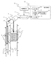
図1は本発明にかかるエレベーター装置の構成を示す。エレベーター装置は、一般的なエレベーター装置の機械システムと同様に、かご1、錘2、ロープ3、プーリ4、巻上機5、逸らせ車6、ガイド7、レール8、ガイド9、レール10、秤装置14などを備えている。かご1と錘2はロープ3で連結されている。ロープ3はプーリ4に巻き掛けられている。プーリ4を巻上機5により回転駆動する事で、かご1は上下方向に運行する。かご1の積載重量(L)は秤装置14を用いて検出する。かご1に定格の半分の重量が積載された場合、錘2とかご1は釣合う。巻上機5には駆動軸のトルクを検出するトルクセンサが設けられている。
FIG. 1 shows the configuration of an elevator apparatus according to the present invention. The elevator apparatus has a
エレベーター装置の運転は、制御装置12がインバーター11を制御して巻上機5を駆動する事で行なわれる。制御装置12は推定装置13と繋がっている。推定装置13は、かご1の走行中の駆動力損失(走行ロス)を特定してその特性を保存し、保存した特性から駆動力損失を推定する。以下では、駆動力損失を特定してその特性を保存する事を「同定」、保存した特性から駆動力損失を推定する事を「推定」、という。
The operation of the elevator device is performed by the
推定装置13は、信号を受け取る入力部21と、受け取った信号を処理する処理部22と、制御装置12にデータ信号を出力する出力部23と、データを記憶する記憶部24を備えている。入力部21には、インバーター11から駆動力(Fiq)を算出するための信号が入力され、制御装置12からはかご1の位置信号、加減速度パターン信号、現在の積載状態に相当する信号、推定装置13への指令信号などが入力される。これらの信号を受け取る処理部22は、制御装置12からの指令信号に従って動作する。この動作のうちの駆動力損失を同定する処理においては、入力された信号にかかる情報を一時的に記憶し、また、記憶した情報を読み出す必要があるため、処理部22と記憶部24は相互に情報の送受ができる構成となっている。
The
処理部22において同定された駆動力損失や推定された駆動力損失は、出力部23に伝達され、制御装置12に入力される。本実施の形態にかかる構成では、制御装置12にアクセスする事で、同定した駆動力損失や現在の推定駆動力損失を確認する事が可能である。尚、推定装置13へ前述の信号が入力されるのであれば、インバーター11や制御装置12以外からの入力でも駆動力損失の同定に利用できる。巻上機5の駆動力を算出するための信号には、巻上機のトルク電流値信号、トルクセンサの出力信号、インバーター11のトルク指令信号、トルク電流指令信号などが利用できる。
The driving force loss identified in the
次に、推定装置13に入力された信号から駆動力損失を学習(推定)するための数値モデルについて説明する。駆動力損失には、ガイド7とレール8の接触による摩擦損失、ガイド9とレール10の接触による摩擦損失、巻上機5の回転損失、並びに、逸らせ車6のような滑車類の軸受けの回転損失の全てが含まれている。この内、ガイド(7および9)とレール(8および10)の接触状態は、かご1の位置で異なるため、その接触に起因する摩擦損失は、かご位置xに依存する傾向がある。一方、回転損失は、回転軸にかかる軸力に比例するため、かご1の積載重量Lに比例する傾向がある。そのため、数値モデルとしては、積載重量Lに比例する数値モデルや、かご位置xに依存する数値モデルや、これら2つの数値モデルを組み合わせたモデルなどが考えられる。
Next, a numerical model for learning (estimating) a driving force loss from a signal input to the
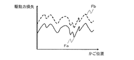
駆動力損失がかご位置xに依存する傾向と積載重量Lに比例する傾向を持つことから、積載重量が異なる場合の駆動力損失は、かご位置xに依存する同一のプロファイル形状を維持しながら、積載重量Lに依存するロス分が全体に加減されるような傾向を示す。かご位置ごとの駆動力損失を図2に例示する。駆動力損失Faはかごに積載がない場合を示し、駆動力損失Fbはかごに積載がある場合を示している。 Since the driving force loss tends to depend on the car position x and is proportional to the load weight L, the driving force loss when the load weight is different maintains the same profile shape depending on the car position x. It shows a tendency that the loss depending on the load weight L is adjusted as a whole. The driving force loss for each car position is illustrated in FIG. The driving force loss Fa indicates the case where the car is not loaded, and the driving force loss Fb indicates the case where the car is loaded.
推定装置13は、かご位置xに依存する傾向と積載重量Lに比例する傾向の両方を的確に捉えるため、図3に示す式1に基づいて駆動力損失を同定して推定する。ここで、駆動力損失Floss(x,L)は、かご位置xと、かごの積載重量Lの関数であることを示している。積載重量Lは、錘2とかご1が釣合う状態を基準としている。
The
式1において、右辺の第1項は積載重量に依存する駆動力損失(第1の駆動力損失)、右辺の第2項はかご位置に依存する駆動力損失(第2の駆動力損失)をあらわす。式1における積載重量Lへの比例定数k1[loss]と、かご位置xに依存する駆動力損失成分k2[loss]を同定すれば、かご位置xと積載重量Lを引数として、所定状態での駆動力損失Floss(x,L)を推定する事が可能となる。
In
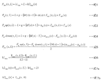
巻上機5の駆動力Fiq(x,L)は、かご位置x及び積載重量Lの関数で、式2に示す釣合い関係を満足する。式2によれば、駆動力Fiq(x,L)は、かご等に影響するロープ/ケーブル類の重量に起因する力Fcab(x)、錘とかごが釣合った状態における、かごや錘の他、ロープ/ケーブル類を含む駆動システム全体の慣性質量M(x)、重力加速度g、かご位置xに対応したかごの加速度α(x)から、推定することができる。ここで、各項の正負符号はかご上側方向を正として示している。駆動力損失Flossは走行方向に対して逆向きに働くため、正負符号で示している。駆動力Fiqについて、かごの上方向運行の場合の釣合い関係を式3に、かごの下方向運行の場合の釣合い関係を式4に、それぞれ示している。
The driving force Fiq (x, L) of the hoisting
積載重量Lを同一とした場合、式3と式4の差により、式5が得られる。式5はかご1を牽引する駆動力Fiq等に基づいて駆動力損失を推定するために使う。推定するためには、制御装置12は、2つの積載重量(L1、L2)について、同一のかご位置xで同一加速度を有する速度変化でかご1を上下運転する。各かご位置での駆動力を記憶してその差分を2で割ると駆動力損失Floss(x,L)が得られる。
When the loading weight L is the same,
このように得られる2つの積載重量(L1、L2)に係る駆動力損失から、式1の比例定数k1[loss]を式6から算出できる。同様に、式1の駆動力損失成分k2[loss]は式7aのように算出できる。
The proportionality constant k1 [loss] of
式5において、同一かご位置で同一加速度を有する速度変化でない場合でも、加速度をふくむ最終項を算出すれば駆動力損失を得ることができるが、加速度を同一とすると、右辺における最終項がゼロになるため、同定の誤差を小さくする事ができる。また、加減速領域を含まない一定速運転での駆動力を取り出しても、最終項がゼロになるため誤差を小さくできるが、同一かご位置で同一加速度を有する速度変化であれば、加減速度が必ず必要となる上下終端階近傍でも誤差なく駆動力損失を同定することができる。
In
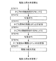
次に、本実施の形態において駆動力損失を推定するための具体的な手順を、図4に基づいて説明する。駆動力損失の学習では、まず積載状態を0%にする(STEP1)。その後、制御装置12にアクセスして、上下方向に往復走行をおこなう(STEP2)。往復走行により得られた駆動力を記憶部24に記憶する(STEP3)。次に、積載状態を100%にして(STEP4)、同様に上下方向に往復走行して(STEP5)、得られた駆動力を記憶部24に記憶する(STEP6)。最後に式6、式7aに基づいて、記憶した駆動力から、駆動力損失を推定するのに必要な情報を同定する(STEP7)。
Next, a specific procedure for estimating the driving force loss in the present embodiment will be described with reference to FIG. In learning of driving force loss, the loading state is first set to 0% (STEP 1). Thereafter, the
同定の精度を望まない場合には、1つの積載状態でのみ運転する方法を用いてもよい。この場合、錘の積み込み作業が不要となる無積載状態でのみ学習するとすれば、式1においてL=0とおく。積載状態に関わらず、駆動力損失成分k2は駆動力損失Floss(x,0)に等しいとする事で、かごの積載重量Lを変更する手間をなくし、また、学習手順STEP4〜6を省略する事ができる。この場合、式7bの駆動力損失成分k2[loss]は、比例定数k1[loss]から独立して求めることができる。
When the accuracy of identification is not desired, a method of operating only in one loading state may be used. In this case, if learning is performed only in a no-load state in which the work of loading the weight is not necessary, L = 0 is set in
以上によれば、駆動力損失を高精度に同定する事が可能であり、同定結果において想定されない異常な大きさの駆動力損失を検出していれば、かごの昇降路内での引っかかりや、レールとの接触異常があると判断する事ができる。 According to the above, it is possible to identify the driving force loss with high accuracy, and if the driving force loss of an abnormal size that is not assumed in the identification result is detected, the car is caught in the hoistway, It can be judged that there is a contact abnormality with the rail.
本実施の形態に係るエレベーター装置は、物件ごとにばらつきがある、かご位置に依存する駆動力損失と積載重量に比例する駆動力損失を精度よく特定する事で、過剰な駆動力損失の有無を確認する事ができ、エレベーター装置の正常な運転が可能か否かを判断できる。また、物件ごとにばらつきがある駆動力損失を、昇降路終端階近傍においても精度よく特定する事で、過剰な駆動力損失の有無を確認する事ができ、昇降路位置に関わらずエレベーター装置の正常な運転が可能か否かを判断できる。 The elevator apparatus according to the present embodiment can accurately detect the driving power loss depending on the car position and the driving power loss proportional to the load weight, which vary from one property to another, so that there is no excess driving power loss. It can be confirmed, and it can be determined whether or not the elevator apparatus can be normally operated. In addition, by accurately identifying the driving force loss that varies from property to property even in the vicinity of the hoistway terminal floor, it is possible to check for the presence or absence of excessive driving force loss, regardless of the hoistway position. It can be determined whether normal operation is possible.
実施の形態2.
本発明の実施の形態2にかかるエレベーター装置は、同定した駆動力損失を用いて推定した駆動力と、直接検知した駆動力を比較する事で異常を検出するものである。ここで、直接検知には、巻上機駆動軸に設けたトルクセンサの出力から駆動力を検知する場合と、巻上機5(インバーター11)のトルク電流から駆動力を推定する場合が含まれる。
The elevator apparatus according to the second embodiment of the present invention detects an abnormality by comparing the driving force estimated using the identified driving force loss with the directly detected driving force. Here, the direct detection includes the case where the driving force is detected from the output of the torque sensor provided on the hoisting machine drive shaft and the case where the driving force is estimated from the torque current of the hoisting machine 5 (inverter 11). .
走行に必要な駆動力Fiqは式2の右辺に基づいて推定できる。この中で、積載重量L及び加速度α(x)に関する情報は、制御装置12が有しているため、制御装置12から推定装置13に情報伝達される。また、駆動力損失は実施の形態1において開示したように同定できる。他に必要な情報は慣性質量M(x)及びケーブル類の重量に起因する力Fcab(x)であるが、これらは上下方向の運転で記憶部24に記憶した駆動力から同定する事ができる。
The driving force Fiq required for traveling can be estimated based on the right side of
慣性質量M(x)と力Fcab(x)を同定するにあたり、積載重量を任意の同一条件とし、加減速度パターンを上下運転で同一のα(x)となるように走行して、直接検知した駆動力を得る。この駆動力に基づき式3と式4から、図5に示す式8が得られる。
In identifying the inertial mass M (x) and the force Fcab (x), the load weight was arbitrarily set to the same condition, and the acceleration / deceleration pattern was run so as to be the same α (x) in the vertical operation and directly detected. Get driving force. Based on this driving force,
式8の駆動力Fdriveは運転に必要な駆動力Fiqから駆動力損失Flossを除外したものである。ロープ/ケーブル類が力Fcabに与える影響はかご位置xに比例して加減される傾向がある。かごを一定速度で走行した範囲におけるかごの異なる位置をかご位置x1、かご位置x2とすると、その位置依存の比例定数k1[cab]が式9により得られる。また、かご位置x0でロープ/ケーブル類が力Fcabに与える影響成分k2[cab]は、式10のように得られる。
The driving force Fdrive of
一般に、ロープ/ケーブル類が力Fcabに与える影響はかごが中間の位置にある際にゼロとなるように設計されており、かご位置x0はかご中間位置までの距離を示す。かご位置に依存するケーブル類の重量による力Fcab(x)は式11に基づいて定められる。慣性質量M(x)は式8から式12により得られることがわかる。
In general, the influence of the ropes / cables on the force Fcab is designed to be zero when the car is at an intermediate position, and the car position x0 indicates the distance to the car intermediate position. The force Fcab (x) due to the weight of the cables depending on the car position is determined based on
以上のように、式2の右辺に示される各項は、予め制御装置12が有する情報、及び、上下運転による学習走行により得られた駆動力から推定できる。この推定された駆動力Fiqと直接検知した駆動力Fiqを比較して、直接検知した駆動力Fiqの方が大きい場合にひっかかりやレールとの接触異常が生じていると判断する事で常時異常の監視ができ、迅速に走行異常検出をする事が可能となる。尚、推定された駆動力より直接検知した駆動力の方が大きいと判断する事には、検知や同定による誤差やばらつきを予め一定値として定めて(以下、定めた大きさを規定値とする)、推定された駆動力より直接検知した駆動力の方が規定値以上に大きくなるときや、推定された駆動力より直接検知した駆動力の方が小さいが、推定された駆動力と直接検知した駆動力の差が規定値よりも小さいときに異常と判断することも含まれる。
As described above, each term shown on the right side of
実施の形態3.
本発明の実施の形態3にかかるエレベーター装置は、走行時の駆動力から駆動力損失を高精度に同定してその影響を除外する事で、精度良く積載重量を推定するものである。積載重量Lの推定式は式1を式2に代入して変形する事で図6に示す式13のように得られる。式13の右辺には積載重量に関する項はない。
The elevator apparatus according to the third embodiment of the present invention accurately estimates the load weight by accurately identifying the driving force loss from the driving force during traveling and excluding the influence thereof. A formula for estimating the load weight L is obtained by substituting
ここで、駆動力Fiq(x,L)は走行中に直接検知した力を表す。右辺の各係数を用いて演算する事で積載重量Lを精度良く推定する事ができる。この結果を用いれば、運行中には積載重量を高精度に推定することができ、必要な慣性質量や駆動力を判断して制御パラメーターを決定する事で性能向上を図る事ができる。また、精度良く推定された積載重量を、かご停止中に計測された秤装置14による積載重量と比較する事で、秤装置14を高精度に補正する事ができる。
Here, the driving force Fiq (x, L) represents a force directly detected during traveling. By calculating using the coefficients on the right side, the loaded weight L can be accurately estimated. If this result is used, it is possible to estimate the load weight with high accuracy during operation, and it is possible to improve performance by determining necessary inertial mass and driving force and determining control parameters. Further, the weighing
エレベーター装置は、積載重量に基づいて運転負荷を推定し、巻上機5やインバーター11の能力により許容される限度で運転速度を高くして、運行効率を向上する制御方式を適用している。実施の形態3によれば、エレベーター装置は、積載重量値を高精度に推定できて推定誤差を小さくできるので、運行効率をさらに向上する事ができる。例えば、巻上機5の能力をその定格電流を超えない範囲で利用するように速度を決定するには、式14と式15が用いられる。
The elevator apparatus estimates a driving load based on the loaded weight, applies a control system that increases the driving speed to the limit allowed by the capabilities of the hoist 5 and the
力行走行時における最大速時の速度Vpは、駆動力損失Floss(x,L)、巻上機の定格電力Ht、定格積載量Lrated、かご内の積載重量L、カウンタ率γ、かご積載重量の検出誤差Er、電動機やインバーターの力行走行時効率ηpに依存する。同様に、回生走行時における最大速時の速度Vrは、駆動力損失Floss(x,L)、巻上機の定格電力Ht、定格積載量Lrated、かご内の積載重量L、カウンタ率γ、かご積載重量の検出誤差Er、電動機やインバーターの回生走行時効率ηrに依存する。カウンタ率γは定格積載の50%で錘と釣合う場合に0.5とする。 The speed Vp at the maximum speed during power running is the driving power loss Floss (x, L), the rated power Ht of the hoist, the rated load capacity Lrated, the load weight L in the car, the counter rate γ, and the car load weight. It depends on the detection error Er and the power running efficiency ηp of the electric motor and the inverter. Similarly, the speed Vr at the maximum speed during regenerative travel is the driving force loss Floss (x, L), the rated power Ht of the hoisting machine, the rated load amount Lrated, the load weight L in the car, the counter rate γ, the car It depends on the detection error Er of the loaded weight and the efficiency ηr during regenerative travel of the electric motor or the inverter. The counter rate γ is set to 0.5 when 50% of the rated load is balanced with the weight.
これらのパラメーターのうち駆動力損失以外は推定装置13の記憶部24に格納されており、速度Vの演算時に該当するパラメーターは記憶部24から読み出される。かご負荷の検出誤差Erや駆動力損失Floss(x,L)にはばらつきがあるものの、想定される最大値を当てはめて速度を求めれば、定格電流を超えることなく運転することが可能である。特に、本実施の形態にかかる推定装置13により精度良く推定された積載重量Lを用いれば検出誤差Erを小さくできる。また実施の形態1にかかる駆動力損失の同定により駆動力損失Flossを精度良く推定すれば、そのばらつきを小さく見積る事ができ、速度を上げて運行効率を向上する事ができる。
Among these parameters, those other than the driving force loss are stored in the
本発明にかかる積載重量の推定では、加減速するかご位置での駆動力損失、及び、加速度の影響が考慮されているため、最大速度に至る前の加減速中でも精度よく推定できる。また積載重量を精度よく特定でき、秤装置の代替とする事ができる。また積載重量を精度よく特定でき、必要以上の誤差を見込まずに最大限大きな速度で運転することができる。 In the estimation of the load weight according to the present invention, since the influence of the driving force loss and acceleration at the position of the car to be accelerated / decelerated is taken into consideration, it can be accurately estimated even during acceleration / deceleration before reaching the maximum speed. In addition, the load weight can be specified with high accuracy and can be used as an alternative to the weighing device. In addition, the load weight can be accurately identified, and the vehicle can be operated at the maximum speed without expecting more errors than necessary.
1 かご、5 巻上機、11 インバーター、12 制御装置、13 推定装置。 1 car, 5 hoisting machine, 11 inverter, 12 control device, 13 estimation device.
Claims (10)
前記ロープを巻き上げる巻上機と、
前記巻上機の駆動を制御する制御装置と、
前記かごの積載重量に依存する第1の駆動力損失を数値モデルに基づいて同定し、前記数値モデルから駆動力損失を推定する推定装置と
を備えたことを特徴とするエレベーター装置。 Whether it is connected with a weight and a rope,
A hoist to wind up the rope;
A control device for controlling the driving of the hoisting machine;
An elevator apparatus comprising: an estimation device that identifies a first driving force loss depending on a load weight of the car based on a numerical model, and estimates the driving force loss from the numerical model.
前記推定装置は、上方向の運行で直接検出された第1の駆動力と下方向の運行で検出された第2の駆動力から前記第1の駆動力損失および前記第2の駆動力損失を同定することを特徴とする請求項3に記載のエレベーター装置。 The control device operates the car in the vertical direction with the same acceleration at a predetermined car position,
The estimation device calculates the first driving force loss and the second driving force loss from the first driving force detected directly in the upward operation and the second driving force detected in the downward operation. The elevator apparatus according to claim 3, wherein the elevator apparatus is identified.
前記推定装置は、上方向の運行で直接検出された第1の駆動力と下方向の運行で検出された第2の駆動力から前記第1の駆動力損失および前記第2の駆動力損失を同定することを特徴とする請求項4に記載のエレベーター装置。 The control device operates the car in the vertical direction with the same acceleration at a predetermined car position,
The estimation device calculates the first driving force loss and the second driving force loss from the first driving force detected directly in the upward operation and the second driving force detected in the downward operation. The elevator apparatus according to claim 4, wherein the elevator apparatus is identified.
前記ロープを巻き上げる巻上機と、
前記巻上機の駆動を制御する制御装置と、
前記かごの積載重量に依存する第1の駆動力損失およびかご位置に依存する第2の駆動力損失を数値モデルとして同定し、同定した前記数値モデルと、直接検知した駆動力と、駆動システムの慣性質量と、前記かごの加速度と、ケーブル重量により加わる力とに基づいて、前記かごの積載重量を推定する推定装置と
を備えたことを特徴とするエレベーター装置。 Whether it is connected with a weight and a rope,
A hoist to wind up the rope;
A control device for controlling the driving of the hoisting machine;
The first driving force loss that depends on the load weight of the car and the second driving force loss that depends on the car position are identified as numerical models, and the identified numerical model, the directly detected driving force, An elevator apparatus comprising: an estimation device that estimates a load weight of the car based on an inertial mass, an acceleration of the car, and a force applied by a cable weight.
Priority Applications (1)
| Application Number | Priority Date | Filing Date | Title |
|---|---|---|---|
| JP2013516245A JP5634603B2 (en) | 2011-05-20 | 2012-04-06 | Elevator equipment |
Applications Claiming Priority (4)
| Application Number | Priority Date | Filing Date | Title |
|---|---|---|---|
| JP2011113612 | 2011-05-20 | ||
| JP2011113612 | 2011-05-20 | ||
| PCT/JP2012/059562 WO2012160888A1 (en) | 2011-05-20 | 2012-04-06 | Elevator apparatus |
| JP2013516245A JP5634603B2 (en) | 2011-05-20 | 2012-04-06 | Elevator equipment |
Publications (2)
| Publication Number | Publication Date |
|---|---|
| JPWO2012160888A1 JPWO2012160888A1 (en) | 2014-07-31 |
| JP5634603B2 true JP5634603B2 (en) | 2014-12-03 |
Family
ID=47216974
Family Applications (1)
| Application Number | Title | Priority Date | Filing Date |
|---|---|---|---|
| JP2013516245A Active JP5634603B2 (en) | 2011-05-20 | 2012-04-06 | Elevator equipment |
Country Status (4)
| Country | Link |
|---|---|
| JP (1) | JP5634603B2 (en) |
| CN (1) | CN103492301B (en) |
| DE (1) | DE112012002180B4 (en) |
| WO (1) | WO2012160888A1 (en) |
Families Citing this family (5)
| Publication number | Priority date | Publication date | Assignee | Title |
|---|---|---|---|---|
| CN106608571A (en) * | 2015-10-26 | 2017-05-03 | 天津鑫宝龙电梯集团有限公司 | Elevator weighing system capable of precisely weighing |
| JP6812506B2 (en) * | 2019-06-27 | 2021-01-13 | 東芝エレベータ株式会社 | Elevator monitoring method and elevator monitoring device |
| CN116056995A (en) * | 2020-08-04 | 2023-05-02 | 通力股份公司 | Drive system and method for controlling the drive system |
| CN116022616A (en) * | 2021-10-25 | 2023-04-28 | 青岛海尔科技有限公司 | Elevator control method, device, electronic device and storage medium |
| DE102024110929A1 (en) * | 2024-04-18 | 2025-04-17 | Tk Elevator Innovation And Operations Gmbh | Method for wear detection in an elevator system and elevator system |
Citations (8)
| Publication number | Priority date | Publication date | Assignee | Title |
|---|---|---|---|---|
| JPS61282276A (en) * | 1985-06-07 | 1986-12-12 | 株式会社日立製作所 | Load compensator for elevator |
| JPH0470906A (en) * | 1990-07-04 | 1992-03-05 | Hitachi Ltd | Control device |
| WO2005102895A1 (en) * | 2004-03-30 | 2005-11-03 | Mitsubishi Denki Kabushiki Kaisha | Control device of elevator |
| JP2006193297A (en) * | 2005-01-14 | 2006-07-27 | Mitsubishi Electric Corp | Elevator equipment |
| JP2009113979A (en) * | 2007-11-09 | 2009-05-28 | Mitsubishi Electric Corp | Elevator control device |
| WO2011027463A1 (en) * | 2009-09-04 | 2011-03-10 | 三菱電機株式会社 | Elevator control device |
| JP2011111259A (en) * | 2009-11-25 | 2011-06-09 | Mitsubishi Electric Corp | Elevator control device |
| WO2011108047A1 (en) * | 2010-03-03 | 2011-09-09 | 三菱電機株式会社 | Control device for elevator |
Family Cites Families (6)
| Publication number | Priority date | Publication date | Assignee | Title |
|---|---|---|---|---|
| JPH06321440A (en) | 1993-05-11 | 1994-11-22 | Mitsubishi Electric Corp | Elevator controller |
| SG71932A1 (en) * | 1998-07-30 | 2000-04-18 | Inventio Ag | Method of force limitation for automatic elevator doors |
| WO2005005300A1 (en) * | 2003-07-09 | 2005-01-20 | Kone Corporation | Control of an elevator |
| EP1731466B1 (en) | 2004-03-29 | 2012-04-25 | Mitsubishi Electric Corporation | Elevator control device |
| KR20060129506A (en) | 2006-09-25 | 2006-12-15 | 미쓰비시덴키 가부시키가이샤 | Elevator counterweight |
| KR101157185B1 (en) * | 2009-04-03 | 2012-07-03 | 유경오토메틱스(주) | Elevator System And Control Method For The Same |
-
2012
- 2012-04-06 WO PCT/JP2012/059562 patent/WO2012160888A1/en not_active Ceased
- 2012-04-06 CN CN201280019460.8A patent/CN103492301B/en active Active
- 2012-04-06 DE DE112012002180.0T patent/DE112012002180B4/en active Active
- 2012-04-06 JP JP2013516245A patent/JP5634603B2/en active Active
Patent Citations (8)
| Publication number | Priority date | Publication date | Assignee | Title |
|---|---|---|---|---|
| JPS61282276A (en) * | 1985-06-07 | 1986-12-12 | 株式会社日立製作所 | Load compensator for elevator |
| JPH0470906A (en) * | 1990-07-04 | 1992-03-05 | Hitachi Ltd | Control device |
| WO2005102895A1 (en) * | 2004-03-30 | 2005-11-03 | Mitsubishi Denki Kabushiki Kaisha | Control device of elevator |
| JP2006193297A (en) * | 2005-01-14 | 2006-07-27 | Mitsubishi Electric Corp | Elevator equipment |
| JP2009113979A (en) * | 2007-11-09 | 2009-05-28 | Mitsubishi Electric Corp | Elevator control device |
| WO2011027463A1 (en) * | 2009-09-04 | 2011-03-10 | 三菱電機株式会社 | Elevator control device |
| JP2011111259A (en) * | 2009-11-25 | 2011-06-09 | Mitsubishi Electric Corp | Elevator control device |
| WO2011108047A1 (en) * | 2010-03-03 | 2011-09-09 | 三菱電機株式会社 | Control device for elevator |
Also Published As
| Publication number | Publication date |
|---|---|
| DE112012002180B4 (en) | 2018-05-03 |
| CN103492301A (en) | 2014-01-01 |
| CN103492301B (en) | 2015-12-09 |
| JPWO2012160888A1 (en) | 2014-07-31 |
| WO2012160888A1 (en) | 2012-11-29 |
| DE112012002180T5 (en) | 2014-02-13 |
Similar Documents
| Publication | Publication Date | Title |
|---|---|---|
| AU2011298833B2 (en) | Method for controlling a drive motor of a lift system | |
| JP5634603B2 (en) | Elevator equipment | |
| CN102781801B (en) | Control device for elevator | |
| US11554933B2 (en) | Elevator | |
| JP5985057B2 (en) | Door device and door control method | |
| JP6218706B2 (en) | Elevator control device and elevator control method | |
| CN106794958A (en) | The control device of elevator | |
| CN105793183B (en) | Elevator device and control method thereof | |
| CN103079978B (en) | Control device for elevator | |
| KR101261763B1 (en) | Control device for elevator | |
| TWI377168B (en) | Automatic inspecting device for an elevator and automatic inspecting method for an elevator | |
| CN112752725B (en) | Characteristic control device for speed governor system and elevator device | |
| US12528668B2 (en) | Method for testing safety characteristics of an elevator | |
| CN100522781C (en) | Control system of elevator | |
| CN101223096B (en) | Elevator speed control device and speed control method | |
| CA3185562A1 (en) | A drive system and method for controlling a drive system | |
| JP2021116148A (en) | Wear inspection system of rope-type elevator and wear inspection method | |
| CN115551793B (en) | Elevator abnormality detection device | |
| JP2018090403A (en) | Elevator control device | |
| HK40062528A (en) | A method for testing safety characteristics of an elevator | |
| CN105143079B (en) | The control device of elevator |
Legal Events
| Date | Code | Title | Description |
|---|---|---|---|
| A131 | Notification of reasons for refusal |
Free format text: JAPANESE INTERMEDIATE CODE: A131 Effective date: 20140603 |
|
| A521 | Request for written amendment filed |
Free format text: JAPANESE INTERMEDIATE CODE: A523 Effective date: 20140731 |
|
| TRDD | Decision of grant or rejection written | ||
| A01 | Written decision to grant a patent or to grant a registration (utility model) |
Free format text: JAPANESE INTERMEDIATE CODE: A01 Effective date: 20140916 |
|
| A61 | First payment of annual fees (during grant procedure) |
Free format text: JAPANESE INTERMEDIATE CODE: A61 Effective date: 20141014 |
|
| R150 | Certificate of patent or registration of utility model |
Ref document number: 5634603 Country of ref document: JP Free format text: JAPANESE INTERMEDIATE CODE: R150 |
|
| R250 | Receipt of annual fees |
Free format text: JAPANESE INTERMEDIATE CODE: R250 |
|
| R250 | Receipt of annual fees |
Free format text: JAPANESE INTERMEDIATE CODE: R250 |
|
| R250 | Receipt of annual fees |
Free format text: JAPANESE INTERMEDIATE CODE: R250 |
|
| R250 | Receipt of annual fees |
Free format text: JAPANESE INTERMEDIATE CODE: R250 |
|
| R250 | Receipt of annual fees |
Free format text: JAPANESE INTERMEDIATE CODE: R250 |
|
| R250 | Receipt of annual fees |
Free format text: JAPANESE INTERMEDIATE CODE: R250 |
|
| R250 | Receipt of annual fees |
Free format text: JAPANESE INTERMEDIATE CODE: R250 |
|
| R250 | Receipt of annual fees |
Free format text: JAPANESE INTERMEDIATE CODE: R250 |
|
| R250 | Receipt of annual fees |
Free format text: JAPANESE INTERMEDIATE CODE: R250 |