JP5634403B2 - Microlithography projection exposure apparatus having two or more operating states - Google Patents
Microlithography projection exposure apparatus having two or more operating states Download PDFInfo
- Publication number
- JP5634403B2 JP5634403B2 JP2011528202A JP2011528202A JP5634403B2 JP 5634403 B2 JP5634403 B2 JP 5634403B2 JP 2011528202 A JP2011528202 A JP 2011528202A JP 2011528202 A JP2011528202 A JP 2011528202A JP 5634403 B2 JP5634403 B2 JP 5634403B2
- Authority
- JP
- Japan
- Prior art keywords
- mask
- centroid
- exposure apparatus
- vector
- point
- Prior art date
- Legal status (The legal status is an assumption and is not a legal conclusion. Google has not performed a legal analysis and makes no representation as to the accuracy of the status listed.)
- Expired - Fee Related
Links
Images


Classifications
-
- G—PHYSICS
- G03—PHOTOGRAPHY; CINEMATOGRAPHY; ANALOGOUS TECHNIQUES USING WAVES OTHER THAN OPTICAL WAVES; ELECTROGRAPHY; HOLOGRAPHY
- G03F—PHOTOMECHANICAL PRODUCTION OF TEXTURED OR PATTERNED SURFACES, e.g. FOR PRINTING, FOR PROCESSING OF SEMICONDUCTOR DEVICES; MATERIALS THEREFOR; ORIGINALS THEREFOR; APPARATUS SPECIALLY ADAPTED THEREFOR
- G03F7/00—Photomechanical, e.g. photolithographic, production of textured or patterned surfaces, e.g. printing surfaces; Materials therefor, e.g. comprising photoresists; Apparatus specially adapted therefor
- G03F7/70—Microphotolithographic exposure; Apparatus therefor
- G03F7/70425—Imaging strategies, e.g. for increasing throughput or resolution, printing product fields larger than the image field or compensating lithography- or non-lithography errors, e.g. proximity correction, mix-and-match, stitching or double patterning
- G03F7/70475—Stitching, i.e. connecting image fields to produce a device field, the field occupied by a device such as a memory chip, processor chip, CCD, flat panel display
-
- G—PHYSICS
- G03—PHOTOGRAPHY; CINEMATOGRAPHY; ANALOGOUS TECHNIQUES USING WAVES OTHER THAN OPTICAL WAVES; ELECTROGRAPHY; HOLOGRAPHY
- G03F—PHOTOMECHANICAL PRODUCTION OF TEXTURED OR PATTERNED SURFACES, e.g. FOR PRINTING, FOR PROCESSING OF SEMICONDUCTOR DEVICES; MATERIALS THEREFOR; ORIGINALS THEREFOR; APPARATUS SPECIALLY ADAPTED THEREFOR
- G03F7/00—Photomechanical, e.g. photolithographic, production of textured or patterned surfaces, e.g. printing surfaces; Materials therefor, e.g. comprising photoresists; Apparatus specially adapted therefor
- G03F7/70—Microphotolithographic exposure; Apparatus therefor
- G03F7/70058—Mask illumination systems
- G03F7/70191—Optical correction elements, filters or phase plates for controlling intensity, wavelength, polarisation, phase or the like
-
- G—PHYSICS
- G03—PHOTOGRAPHY; CINEMATOGRAPHY; ANALOGOUS TECHNIQUES USING WAVES OTHER THAN OPTICAL WAVES; ELECTROGRAPHY; HOLOGRAPHY
- G03F—PHOTOMECHANICAL PRODUCTION OF TEXTURED OR PATTERNED SURFACES, e.g. FOR PRINTING, FOR PROCESSING OF SEMICONDUCTOR DEVICES; MATERIALS THEREFOR; ORIGINALS THEREFOR; APPARATUS SPECIALLY ADAPTED THEREFOR
- G03F7/00—Photomechanical, e.g. photolithographic, production of textured or patterned surfaces, e.g. printing surfaces; Materials therefor, e.g. comprising photoresists; Apparatus specially adapted therefor
- G03F7/70—Microphotolithographic exposure; Apparatus therefor
- G03F7/70216—Mask projection systems
- G03F7/70283—Mask effects on the imaging process
Description
本発明は、少なくとも2つの動作状態を有するマイクロ電子構成要素を生成するためのマイクロリソグラフィ投影露光装置、及びリソグラフィを用いてマイクロ電子構成要素を生成する方法に関する。 The present invention relates to a microlithographic projection exposure apparatus for generating a microelectronic component having at least two operating states and a method for generating a microelectronic component using lithography.
導入部で示した種類のマイクロリソグラフィ投影露光装置及び方法は、例えば、US 6,295,119B1及びUS 6,526,118B2から公知である。 A microlithographic projection exposure apparatus and method of the kind indicated in the introduction is known, for example, from US 6,295,119 B1 and US 6,526,118 B2.
マイクロ電子構成要素を生成するのに用いられるマイクロリソグラフィ投影露光装置は、特に、構造担持マスク、いわゆるレチクルを照明するための光源及び照明系、並びにマスクをウェーハである基板上に結像するための投影光学ユニットを含む。この基板は、露光時に化学的に変質される感光層を含む。これをリソグラフィ段階とも呼ぶ。この場合、レチクルは、マイクロリソグラフィ投影露光装置の投影光学ユニットの物体平面に配置され、ウェーハは、その像平面に配置される。感光層の露光及び更に別の化学工程がマイクロ電子構成要素を生成する。 The microlithographic projection exposure apparatus used to generate the microelectronic components is in particular a structure-bearing mask, a light source and illumination system for illuminating a so-called reticle, and for imaging the mask onto a substrate which is a wafer. Includes a projection optical unit. The substrate includes a photosensitive layer that is chemically altered upon exposure. This is also called a lithography stage. In this case, the reticle is placed on the object plane of the projection optical unit of the microlithographic projection exposure apparatus, and the wafer is placed on the image plane. Exposure of the photosensitive layer and further chemical processes produce microelectronic components.
マイクロリソグラフィ投影露光装置は、多くの場合にいわゆるスキャナとして作動される。このスキャナ作動は、レチクルが走査方向に沿ってスロット状照明視野を通して移動され、同時にウェーハが、投影光学ユニットの像平面内で相応に移動されることを意味する。レチクルの速度とウェーハの速度との比は、通常は1よりも小さく、投影光学ユニットの倍率に対応する。 Microlithographic projection exposure apparatuses often operate as so-called scanners. This scanner operation means that the reticle is moved through the slotted illumination field along the scanning direction and at the same time the wafer is moved accordingly in the image plane of the projection optical unit. The ratio of reticle speed to wafer speed is usually less than 1 and corresponds to the magnification of the projection optical unit.
この場合、照明系及び投影光学ユニットの光学構成要素は、屈折構成要素、反射構成要素、又は回折構成要素のうちのいずれかとすることができる。屈折構成要素と反射構成要素と回折構成要素との組合せも可能である。同様に、レチクルも、反射方式又は透過方式のいずれかに実施することができる。そのような装置は、約100nmよりも短い波長、特に5nmと15nmの間の波長を有する放射線を用いて作動される場合には、完全に反射構成要素から構成される。 In this case, the optical components of the illumination system and the projection optical unit can be any of refractive components, reflective components, or diffractive components. Combinations of refractive, reflective and diffractive components are also possible. Similarly, the reticle can be implemented in either a reflective or transmissive manner. Such devices are composed entirely of reflective components when operated with radiation having a wavelength shorter than about 100 nm, in particular between 5 nm and 15 nm.
そのようなマイクロリソグラフィ投影露光装置は、限られた照明視野及び同じく結像することができる限られた視野を有する。しかし、マスクが非常に大きく、完全に結像することができないか、又は完全に照明することができないかのいずれの場合であっても、構造担持マスクは、フォトレジスト層を有する基板が配置された像平面に結像することが望ましい場合がある。 Such a microlithographic projection exposure apparatus has a limited illumination field and a limited field that can also be imaged. However, even if the mask is very large and cannot be fully imaged or fully illuminated, the structure-bearing mask is placed with a substrate having a photoresist layer. It may be desirable to form an image on a different image plane.
マスクが、照明又は結像することができる領域よりも一方向にのみ大きい場合には、マイクロリソグラフィ投影露光装置は、マスクが、スロット状照明視野を通してこの方向に移動され、同時にウェーハが、投影光学ユニットの像平面内で相応に移動されるようにスキャナとして作動させることができる。このスキャナ作動は、少なくとも原理的に上述の方向に任意のサイズのマスクを照明及び結像することができることを意味する。 If the mask is larger in only one direction than the area that can be illuminated or imaged, the microlithographic projection exposure apparatus will move the mask in this direction through the slotted illumination field and at the same time the wafer will be projected optically. It can be operated as a scanner to be moved accordingly in the image plane of the unit. This scanner operation means that a mask of any size can be illuminated and imaged at least in principle in the above-mentioned direction.
しかし、マスクが、結像又は照明することができる領域よりも両方向に大きい場合には、この結像及び照明を走査によって調整することはできない。そのような場合には、構造担持マスクは、個々に結像又は照明される少なくとも2つの部分領域に分割される。この分割を走査処理と条件付きで組み合わせることができる。この場合、少なくとも2つの部分領域の中点は、少なくとも2つの部分領域の組合せが個々の部分領域の各々よりも大きいような走査方向に対して垂直の距離の位置に存在する。すなわち、走査方向の移動との組合せで、比較的大きい構造担持マスクを照明及び結像することができる。 However, if the mask is larger in both directions than the area that can be imaged or illuminated, this imaging and illumination cannot be adjusted by scanning. In such a case, the structure-bearing mask is divided into at least two partial areas that are individually imaged or illuminated. This division can be combined with scanning processing conditionally. In this case, the midpoint of the at least two partial areas exists at a position perpendicular to the scanning direction such that the combination of the at least two partial areas is larger than each of the individual partial areas. That is, a relatively large structure carrying mask can be illuminated and imaged in combination with movement in the scanning direction.
しかし、マスク構造の完全な像を感光層内に生成するためには、部分領域が少なくとも部分的に重なると有利である。この重ね合わせは、不注意に結像又は照明されないいかなるマスク領域も存在しないことを保証することを可能にする。しかし、これらの重ね合わせ領域は、構造担持マスクの構成において問題をもたらす。特にマスクが垂直に照明されない場合には、マスクの製造時に、投影露光装置内のマスク点に放射線のどの重心方向が存在するかということを考慮すべきである。これらの影響は、放射線の重心方向が垂直照明から異なる程悪化する。重ね合わせ領域のうちの少なくとも1つの部分領域の各点において、第1の重心方向とマスクに対して垂直な正規化ベクトルとの間の角度が3°又はそれよりも大きく、特に6°又はそれよりも大きい場合には、これらの問題を考慮すべきである。 However, in order to produce a complete image of the mask structure in the photosensitive layer, it is advantageous if the partial areas at least partially overlap. This superposition makes it possible to ensure that there are no mask regions that are not inadvertently imaged or illuminated. However, these overlapping areas pose problems in the construction of the structure carrying mask. In particular, when the mask is not illuminated vertically, it should be taken into account which centroid direction of the radiation is present at the mask point in the projection exposure apparatus when the mask is manufactured. These effects are exacerbated as the direction of the center of gravity of the radiation differs from the vertical illumination. At each point of at least one partial region of the overlapping region, the angle between the first centroid direction and the normalization vector perpendicular to the mask is 3 ° or more, in particular 6 ° or more If greater than, these issues should be considered.
入射する放射線の重心方向は、入射する放射線の平均方向を意味すると理解すべきである。ある点が、ビーム円錐の全ての方向から均一に照明される場合には、ビーム円錐の対称軸は重心方向と一致する。不均一照明の場合には、一般的に、各方向が、その方向から到着する放射線の強度で重み付けられるエネルギ重み付き平均が形成される。この場合、重心方向は、平均エネルギ重み付き方向である。 The direction of the center of gravity of the incident radiation should be understood to mean the average direction of the incident radiation. If a point is illuminated uniformly from all directions of the beam cone, the symmetry axis of the beam cone coincides with the direction of the center of gravity. In the case of non-uniform illumination, an energy weighted average is generally formed in which each direction is weighted by the intensity of radiation arriving from that direction. In this case, the center of gravity direction is an average energy weighted direction.
斜照明中には、影付け及びマスク像を歪曲させる投影効果が発生する場合があるから、マスクの製造時に重心方向を考慮すべきである。影効果は、そのような構造担持マスクが完全に平面ではないことに起因して発生する可能性がある。反射マスクの場合には、非反射領域の位置で1つ又はそれよりも多くの被覆層が1つ又はそれよりも多くの反射基部層に付加されるので、これらの領域は高くなっている。従って、マスクのそのような3次元構造は、影効果を招く可能性がある。 During oblique illumination, shadowing and projection effects that distort the mask image may occur, so the center of gravity direction should be considered when manufacturing the mask. Shadow effects can occur due to the fact that such structure-bearing masks are not perfectly planar. In the case of a reflective mask, these areas are elevated because one or more coating layers are applied to one or more reflective base layers at the location of the non-reflective areas. Therefore, such a three-dimensional structure of the mask can lead to shadow effects.
しかし、影及び投影の効果は、マスクの製造時に考慮することができ、その結果、マイクロリソグラフィ投影露光装置の像平面に望ましい像がもたらされる。 However, the effects of shadows and projections can be taken into account when manufacturing the mask, resulting in a desired image in the image plane of the microlithographic projection exposure apparatus.
重ね合わせ領域が2度照明及び結像される場合には、これは、依然として影付け及び投影効果を考慮することを可能にするために、第1及び第2の露光の放射線の重心方向から構成される特定の要件をもたらす。 If the overlap region is illuminated and imaged twice, this is composed of the centroid directions of the radiation of the first and second exposures in order to still allow for shadowing and projection effects to be taken into account. Will result in specific requirements.
本発明は、上述の特定の要件を満たすマイクロリソグラフィ投影露光装置及びマイクロ電子構成要素を生成する方法を提供することを意図している。 The present invention is intended to provide a microlithographic projection exposure apparatus and a method of generating microelectronic components that meet the specific requirements described above.
本発明によると、上述の目的は、物体平面内に反射マスクを含む少なくとも2つの動作状態を有するマイクロ電子構成要素を生成するためのマイクロリソグラフィ投影露光装置を用いて達成される。この場合、マイクロリソグラフィ投影露光装置は、第1の動作状態では、マスクの第1の部分領域が、第1の部分領域の各点において第1の重心方向ベクトルを有する割り当てられた第1の重心方向を有する第1の放射線によって照明され、第2の動作状態では、マスクの第2の部分領域が、第2の部分領域の各点において第2の重心方向ベクトルを有する割り当てられた第2の重心方向を有する第2の放射線によって照明され、第1の部分領域と第2の部分領域とが共通の重ね合わせ領域を有するように構成される。この場合、重ね合わせ領域の少なくとも1つの部分領域の各点では、第1の正規化重心方向ベクトルと、第2の正規化重心方向ベクトルと、マスクに対して垂直な正規化ベクトルとのスカラー三重積は、0.05よりも小さく、好ましくは、0.03よりも小さく、特に好ましくは、0.01よりも小さい。それによって第1及び第2の重心方向ベクトルから平均された重心方向ベクトルが、マスクに対して垂直であり、従って、重ね合わせ領域内で投影及び影の効果を考慮するいかなる必要もないこと、又は第1の重心方向ベクトルと第2の重心方向ベクトルとが方向においてそれ程異ならず、従って、重心方向ベクトルが両方の動作状態において等しいので、いかなる問題も伴わずに投影及び影の効果を考慮することができることのいずれかを保証する。最初の場合には、第1の重心方向ベクトルと第2の重心方向ベクトルとの外積は、マスク上の正規化ベクトルに対して実質的に垂直であり、従って、スカラー三重積は、0.05よりも小さく、好ましくは、0.03よりも小さく、特に好ましくは、0.01よりも小さい。第2の場合には、第1の重心方向ベクトルと第2の重心方向ベクトルとが実質的に同じ方向を有し、従って、外積のマグニチュードは既に小さく、それによってこの場合も外積と、マスクに対して垂直な正規化ベクトルとの間のスカラー積のマグニチュードは、同様に、0.05よりも小さく、好ましくは、0.03よりも小さく、特に好ましくは、0.01よりも小さい。 According to the present invention, the above objective is accomplished with a microlithographic projection exposure apparatus for generating microelectronic components having at least two operating states that include a reflective mask in the object plane. In this case, the microlithographic projection exposure apparatus, in the first operating state, assigns the first centroid to which the first partial area of the mask has a first centroid direction vector at each point of the first partial area. Illuminated by a first radiation having a direction, and in a second operating state, a second partial region of the mask is assigned a second second centroid direction vector at each point of the second partial region. Illuminated by the second radiation having the direction of the center of gravity, the first partial region and the second partial region are configured to have a common overlapping region. In this case, at each point of at least one partial region of the overlapping region, a scalar triple of a first normalized centroid direction vector, a second normalized centroid direction vector, and a normalized vector perpendicular to the mask. The product is less than 0.05, preferably less than 0.03, particularly preferably less than 0.01. So that the centroid direction vector averaged from the first and second centroid direction vectors is perpendicular to the mask, and thus there is no need to take into account the effects of projection and shadows in the overlap region, or Consider the effects of projection and shadow without any problems because the first centroid direction vector and the second centroid direction vector are not so different in direction, and therefore the centroid direction vector is equal in both operating states. Guarantee one of the things that can be done. In the first case, the outer product of the first centroid direction vector and the second centroid direction vector is substantially perpendicular to the normalized vector on the mask, so the scalar triple product is 0.05. Less than, preferably less than 0.03, particularly preferably less than 0.01. In the second case, the first centroid direction vector and the second centroid direction vector have substantially the same direction, so the magnitude of the outer product is already small, so that again in this case the outer product and the mask The magnitude of the scalar product between the normalization vector perpendicular to the same is likewise less than 0.05, preferably less than 0.03, particularly preferably less than 0.01.
重ね合わせ領域が第1の部分領域よりも小さく、第2の部分領域よりも小さい投影露光装置の構成は、第1の部分領域と第2の部分領域との組合せが、第1の部分領域及び第2の部分領域それぞれよりも大きいという効果を有する。これは、全体として大きい構造担持マスクを照明及び結像することができることを意味する。 In the configuration of the projection exposure apparatus in which the overlapping region is smaller than the first partial region and smaller than the second partial region, the combination of the first partial region and the second partial region is the first partial region and It has the effect of being larger than each of the second partial regions. This means that an overall large structure-bearing mask can be illuminated and imaged.
第1の動作状態における反射マスクの向きが、第2の動作状態におけるマスクの向きと物体平面に対して垂直な軸の回りに180°の回転量だけ異なるように投影露光装置が更に構成される場合には、そのような投影露光装置は、特に簡単な方式で達成することができる。それによって物体平面から過度に分離しない入射瞳を有する投影光学ユニットを用いることができる。そのような投影光学ユニットは、回転対称反射構成要素によって具現化することができ、これらの投影光学ユニットは、そのような回転対称を用いない投影光学ユニットよりも製造して測定することが簡単である。 The projection exposure apparatus is further configured such that the orientation of the reflective mask in the first operation state differs from the orientation of the mask in the second operation state by a rotation amount of 180 ° about an axis perpendicular to the object plane. In some cases, such a projection exposure apparatus can be achieved in a particularly simple manner. Thereby, a projection optical unit having an entrance pupil that is not excessively separated from the object plane can be used. Such projection optical units can be embodied by rotationally symmetric reflective components, and these projection optical units are easier to manufacture and measure than projection optical units that do not use such rotational symmetry. is there.
本発明は、更に、少なくとも2つの動作状態を有するマイクロ電子構成要素を生成するためのマイクロリソグラフィ投影露光装置に関する。この場合、マイクロリソグラフィ投影露光装置は、物体平面内に反射マスクを含み、第1の動作状態における反射マスクの向きは、第2の動作状態におけるマスクの向きと物体平面に対して垂直な軸の回りに180°の回転量だけ異なる。これは、マスクにおける照明方向が、両方の動作状態において同じ回転量だけ異なるという利点を有する。それによって達成されることは、反射マスクの場合に斜照明に起因して発生する影響を補償することができるということである。 The invention further relates to a microlithographic projection exposure apparatus for producing a microelectronic component having at least two operating states. In this case, the microlithographic projection exposure apparatus includes a reflective mask in the object plane, and the orientation of the reflective mask in the first operation state is an axis perpendicular to the orientation of the mask in the second operation state and the object plane. The rotation differs by 180 °. This has the advantage that the illumination direction at the mask differs by the same amount of rotation in both operating states. What is achieved thereby is that the influence caused by oblique illumination in the case of a reflective mask can be compensated.
本発明によるマイクロリソグラフィ投影露光装置では、特に5nmと15nmの間の波長を有する放射線を用いることができる。これは、特に小さい構造をそのような装置を利用して結像することができるという利点を有する。 In the microlithographic projection exposure apparatus according to the present invention, radiation having a wavelength between 5 nm and 15 nm can be used. This has the advantage that particularly small structures can be imaged using such a device.
本発明は、更に、物体平面内の反射構造担持マスクが像平面内の基板上に結像されるリソグラフィを用いてマイクロ電子構成要素を生成する方法に関する。本方法は、第1の部分領域の各点において第1の重心方向ベクトルを有する第1の重心方向を有する第1の放射線によるマスクの第1の部分領域の第1の露光、及び第2の部分領域の各点において第2の重心ベクトルを有する第2の重心方向を有する第2の放射線によるマスクの第2の部分領域の第2の露光という段階を含み、第1の部分領域と第2の部分領域は、共通の重ね合わせ領域を有する。この重ね合わせ領域内では、各点において、第1の正規化重心方向ベクトルと、第2の正規化重心方向ベクトルと、マスクに対して垂直な正規化ベクトルとのスカラー三重積は、0.05よりも小さく、好ましくは、0.03よりも小さく、特に好ましくは、0.01よりも小さい。本方法は、特に、製造することが簡単な構造担持マスクを用いることができるという利点を有する。これは、部分領域の第1の露光の重心方向ベクトルと第2の露光の重心方向ベクトルとの特定の関係に起因して投影及び影の効果を簡単な方式で考慮することができるということによるものである。 The invention further relates to a method for producing microelectronic components using lithography in which a reflective structure-bearing mask in the object plane is imaged onto a substrate in the image plane. The method includes a first exposure of a first partial region of a mask with a first radiation having a first centroid direction having a first centroid direction vector at each point of the first partial region, and a second A second exposure of the second partial area of the mask with a second radiation having a second centroid direction having a second centroid vector at each point of the partial area, the first partial area and the second These partial areas have a common overlapping area. Within this overlap region, at each point, a scalar triple product of the first normalized centroid direction vector, the second normalized centroid direction vector, and the normalized vector perpendicular to the mask is 0.05. Less than, preferably less than 0.03, particularly preferably less than 0.01. The method has the advantage in particular that a structure-bearing mask that is easy to manufacture can be used. This is because the effects of projection and shadow can be considered in a simple manner due to the specific relationship between the centroid direction vector of the first exposure and the centroid direction vector of the second exposure of the partial area. Is.
本発明による方法では、特に5nmと15nmの間の波長を有する放射線を用いることができる。これは、そのような放射線を利用して特に小さい構造を結像することができるという利点を有する。 In the method according to the invention, it is possible in particular to use radiation having a wavelength between 5 nm and 15 nm. This has the advantage that particularly small structures can be imaged using such radiation.
更に、本発明による方法は、マスクが、照明視野を通じて第1の露光中に第1の走査方向に沿って移動され、第2の露光中に第2の走査方向に沿って移動される走査処理を用いて第1及び第2の露光が行われるように構成することができる。付加的な走査処理を用いると、一層大きい構造担持マスクを照明及び結像することができる。 Furthermore, the method according to the invention provides a scanning process in which the mask is moved through the illumination field along the first scanning direction during the first exposure and along the second scanning direction during the second exposure. The first and second exposures can be performed using the. With additional scanning processing, larger structure-bearing masks can be illuminated and imaged.
本発明による投影露光装置がスキャナとして作動される場合には、隣接する部分領域の露光中の走査方向は、平行又は反平行とすることができる。露光中にはマスクが必ず開始位置から終了位置へと移動され、開始位置への復帰経路上ではいかなる露光も行われないので、平行な走査方向は、全ての露光段階が等しいという利点を有する。これは、開始位置への復帰経路を同じ精度で達成しなくてもよく、従って、投影露光装置の機械的複雑さから構成される要件がそれ程厳しくないことを意味する。一方、反平行走査方向は、復帰経路上でも露光が行われ、従って、高速な露光作動を可能にすることができるという利点を有する。 When the projection exposure apparatus according to the present invention is operated as a scanner, the scanning direction during exposure of adjacent partial regions can be parallel or anti-parallel. Since the mask is always moved from the start position to the end position during exposure and no exposure is performed on the return path to the start position, the parallel scanning direction has the advantage that all exposure steps are equal. This means that the return path to the starting position does not have to be achieved with the same accuracy, and therefore the requirements consisting of the mechanical complexity of the projection exposure apparatus are not so strict. On the other hand, the anti-parallel scanning direction has an advantage that exposure is performed even on the return path, and thus high-speed exposure operation can be enabled.
本方法又は投影露光装置が、2つの任意の第1の重心方向ベクトルの間、又は2つの任意の第2の重心方向ベクトルの間の最大角度が1°よりも小さいということによって更に特徴付けられる場合には、重ね合わせ領域内には重心方向ベクトルの僅かな変化しか存在しない。これは、重ね合わせ領域内の影及び投影の効果の強度も同様に小さい範囲でしか変化しないという利点を有する。 The method or the projection exposure apparatus is further characterized in that the maximum angle between any two first centroid vectors or between any two second centroid vectors is less than 1 °. In some cases, there is only a slight change in the centroid direction vector in the overlap region. This has the advantage that the intensity of the shadow and projection effects in the overlap region also changes only within a small range.
本方法が、追加的又は代替的に、重ね合わせ領域の各点において第1の重心方向ベクトルと第2の重心方向ベクトルの間の角度が1°よりも小さいように構成される場合には、第1及び第2の露光中の投影及び影の効果は実質的に等しく、従って、これらの効果を構造担持マスクの製造中に比較的簡単な方式で補償することができる。 If the method is additionally or alternatively configured such that the angle between the first centroid direction vector and the second centroid direction vector is less than 1 ° at each point of the overlap region, The effects of projection and shadow during the first and second exposures are substantially equal, so these effects can be compensated in a relatively simple manner during the manufacture of the structure-bearing mask.
重ね合わせ領域の各点において、第1の重心方向ベクトルと第2の重心方向ベクトルとによって形成される平面とマスクに対して垂直な正規化ベクトルとの間の角度が1°よりも小さいような本方法の更に別の構成の場合には、それによって2つの露光にわたって平均された露光放射線の方向がマスクに対して実質的に垂直であるという利点がもたらされる。それによって重ね合わせ領域内で影及び投影の効果が僅かしか発生しないことを保証する。 At each point of the overlap region, the angle between the plane formed by the first centroid direction vector and the second centroid direction vector and the normalization vector perpendicular to the mask is smaller than 1 °. In yet another configuration of the method, this provides the advantage that the direction of the exposure radiation averaged over the two exposures is substantially perpendicular to the mask. This ensures that only a few shadow and projection effects occur in the overlap region.
特に、本方法は、第1の露光と第2の露光の間で物体平面内での構造担持マスクの180°の回転を含むことができる。これは、第1及び第2の露光中に回転に起因してマスクにおける照明方向が異なるという利点を有する。それによって達成されることは、反射マスクの場合に斜照明の結果として発生する効果を補償することができるということである。 In particular, the method can include a 180 ° rotation of the structure-bearing mask in the object plane between the first exposure and the second exposure. This has the advantage that the illumination direction in the mask is different due to rotation during the first and second exposures. What is achieved thereby is that the effects that occur as a result of oblique illumination in the case of a reflective mask can be compensated.
図面を参照して本発明をより詳細に以下に説明する。 The invention is explained in more detail below with reference to the drawings.
参照記号は、図1に例示している物体に1桁又は2桁の番号が付与されるように選択した。更に別の図に例示している物体は、下位2桁が物体を指定し、その上にある桁が、その物体を示している図の番号を指定する3桁又はそれよりも多くを含む参照記号を有する。従って、複数の図に例示している等しい物体の参照番号は、下位2桁に関して一致する。例示的に、参照記号3及び403は、この場合、図1及び図4で物体視野である物体3を示している。従って、場合によっては、ある参照番号を有する物体の説明を先行する図のうちの1つに関する説明において対応する参照番号の下で見出すことができる。
The reference symbols were selected such that the object illustrated in FIG. 1 was given a one or two digit number. The object illustrated in yet another figure is a reference in which the lower two digits specify the object and the digits above it contain three or more digits that specify the figure number representing the object. Have a symbol. Accordingly, the reference numbers of the same objects illustrated in the figures match for the lower two digits. Illustratively, the
図1は、従来技術で公知のもののようなマイクロリソグラフィ投影露光装置の反射投影光学ユニット1の図を示している。投影光学ユニット1は、物体平面5に配置された物体視野3を像平面7内に結像する。更に、構造担持マスク(図面内には例示していない)、いわゆるレチクルが、物体平面5内の物体視野3の位置に配置される。直交座標系を更に例示しており、そのx軸は作図面に向く。この場合、x−y座標面は物体平面1と一致し、z軸は、物体平面1に対して垂直であり、下に向く。投影光学ユニットは光軸9を有し、光軸9は物体視野を通じて延びない。投影光学ユニット1のミラー11は、光軸に関して回転対称な光学面を有する。例示的な実施形態における光路内の第2のミラー上には、開口絞り13が配置される。投影光学ユニット1の効果を物体視野15の中心の主光線及び2つの開口周辺光線17と19という3つの光線を用いて例示している。物体平面に対する垂線に対して6°の角度で進む物体視野15の中心の主光線は、開口絞り13の平面内で光軸と交わる。物体平面5から見ると、主光線15は、入射瞳平面21内で光軸と交わるように見える。従って、開口絞り13の虚像である入射瞳は、入射瞳平面21内に位置する。反射構成の投影光学ユニットの場合に、物体視野から進む放射線の望ましくないいかなる周辺遮光も発生しないように、物体視野3の中心は、光軸9から距離Rの位置にある。
FIG. 1 shows a diagram of a reflective projection
図2は、構造担持マスクの一部分の立面図を略示している。マスクは、基板225上の反射基部層223,及び第1の部分領域229内にのみ付加された吸収剤被覆層227を含む。被覆層227は、通常は約100nmの範囲に厚みhを有する。第1の部分領域227は広がりDを有する。第1の部分領域の中心を231によって示している。この場合、放射線が、マスクに対する垂線に対して角度γを有する重心方向ベクトル235でマスク上に入射すると、被覆層227は反射基部層上に影を投射し、その結果、全体として第2の部分領域232が照明されない。しかし、第2の部分領域は、部分領域231よりも大きい。更に、第2の部分領域の中点は、第1の部分領域の中点231に対して変位している。従って、投影及び影の効果に起因して、非反射領域の拡幅及び変位が発生する。
FIG. 2 schematically shows an elevation view of a portion of the structure-bearing mask. The mask includes a
図3は、一例としてレチクルにおける反射前の放射線の重心方向ベクトル335を直交座標系に例示している。空間的な向きのより明瞭な解説のために、この図は、x−z平面内への重心方向ベクトル335の投影337、及びy−z平面内への重心方向ベクトル335の投影339を示している。重心光線角度αは、投影337とz軸の間の角度を表し、重心光線角度βは、投影339とz軸の間の角度を表している。これらの2つの角度を用いて正規化重心方向ベクトルを明確に説明することができる。反射前の重心方向ベクトルs→は、例示している座標系内で次式によって定められる角度によって説明される。
FIG. 3 illustrates, as an example, a

この場合には、角度は次式によって定められる。
α=arctan(sx/sz)、及び
β=arctan(sy/sz)
In this case, the angle is determined by the following equation.
α = arctan (s x / s z ) and β = arctan (s y / s z )
例示している事例では、成分sx、sy、及びszは全て負である(ベクトル335は左上を向く)。従って、角度α及びβは正である。放射線はレチクルにおいて反射され、レチクルはx−y平面に配置されるので、反射後の放射線の重心方向ベクトル:
In the illustrated example, the components s x , s y , and s z are all negative (
![]()
![]()
に対して次式が成り立つ。 The following equation holds.
更に、反射後の対応する角度に対しては次式が成り立つ。
α’=−α、及び
β’=−β
Furthermore, the following equation holds for the corresponding angle after reflection.
α ′ = − α and β ′ = − β
重心方向ベクトル: Center of gravity direction vector:
![]()
![]()
を物体視野の各点において入射瞳の中心に向くように向けるためには、照明放射線の重心方向ベクトル: To point at the center of the entrance pupil at each point in the object field:
![]()
![]()
は、入射瞳の位置からもたらされる特定のプロフィールを有するべきである。 Should have a specific profile resulting from the position of the entrance pupil.
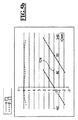
図4aは、図1に例示している投影光学ユニット1の場合に発生するもののような弓形物体視野403の平面図、及び図1に記載のものに対応する軸を有する直交座標系を示している。物体視野403は、光軸409と物体平面との交点を通る中心を有する環状からの抜粋部分である。平均半径Rは、例示している事例では135mmである。この場合、視野のy方向の幅dは8mmである。代替として、湾曲物体視野は、同じ半径を有する互いに対してy方向に変位した2つの円弧によってその境界を定めることができる。図1及び図2に例示しているもののような投影光学ユニットの作動では、物体視野403のある一定の点における放射線の重心方向が、反射レチクルにおける反射の後に実質的に物体視野のこの点と入射瞳の中心との間を繋ぐ線の方向に延びるように物体視野403が照明される。投影露光装置がスキャナとして作動される場合には、走査方向は、物体視野の短い方の広がり方向、すなわち、y方向の方向に延びている。
4a shows a plan view of an
図4bは、特定の例示的な実施形態における重心光線角度のプロフィールを示している。この場合、光軸は、物体視野の中心からR=135mmの距離の位置にあり、入射瞳は、物体平面から1284.4mmの距離に位置する。 FIG. 4 b shows the centroid ray angle profile in certain exemplary embodiments. In this case, the optical axis is located at a distance of R = 135 mm from the center of the object field, and the entrance pupil is located at a distance of 1284.4 mm from the object plane.
これらの値は、重心方向: These values are in the direction of the center of gravity:
![]()
![]()
と物体平面に対する垂線の間に6°の反射角を生成する。 And a reflection angle of 6 ° between the normal to the object plane.
図2に例示している上側半弧しか関係しないので、各値xに対して点(x,y)が、半径R=135mmを有する半円弧上に位置するような厳密に1つの正の値yが存在する。従って、点(x,y)を入射瞳の中心に関連付けることによって角度α’及びβ’を座標xの関数として計算することができる。上述の関係を利用して、これらの角度α’及びβ’から符号変更によって反射前の角度α及びβがもたらされる。この事例では視野のy方向の広がりが8mmであり、各固定値x0に対して点(x0,y0)が物体視野内に位置するような複数の点y0が存在するが、そのような場合でも重心光線角度は、これらの点にわたって大幅には変化しない。更に、本発明による投影露光装置は、通常、構造担持マスクが物体視野を通じてy方向に移動される走査モードで作動される。その結果、座標x0を有するマスクの各点は、全ての点y0にわたって平均された重心光線角度を有する放射線で照明される。これらの理由から、下記の考察では、R=135mmを有する半円弧上の重心光線角度に注意するだけで十分である。 Since only the upper half arc illustrated in FIG. 2 is concerned, for each value x exactly one positive value such that the point (x, y) lies on a semi-arc having a radius R = 135 mm. y exists. Accordingly, the angles α ′ and β ′ can be calculated as a function of the coordinate x by associating the point (x, y) with the center of the entrance pupil. Using the above relationship, sign changes from these angles α ′ and β ′ result in pre-reflection angles α and β. In this example, the spread of the visual field in the y direction is 8 mm, and there are a plurality of points y 0 such that the point (x 0 , y 0 ) is located in the object visual field for each fixed value x 0 . Even in such a case, the barycentric ray angle does not change significantly over these points. Furthermore, the projection exposure apparatus according to the invention is normally operated in a scanning mode in which the structure-bearing mask is moved in the y direction through the object field. As a result, each point of the mask having coordinates x0 is illuminated with radiation having an average centroid ray angles over all points y 0. For these reasons, in the discussion below, it is sufficient to pay attention to the barycentric ray angle on the semicircular arc with R = 135 mm.
図4bを参照すると、−50mmと50mmの間のxにおける角度は、−2.23°と2.23°の間で変化しなければならず、それに対して5.57°と6°の間の角度βの変化が必要であることが明らかになる。しかし、重心光線角度のそのような変化は、構造担持マスクの設計における調整を必要とする。重心方向ベクトルが構造担持マスクに対して垂線ではない場合には、影付け及び投影効果に起因して構造像の変位を招く。重心方向ベクトルがマスク上の全ての位置で等しい限り、結果は実質的に広域変位である。しかし、重心方向ベクトルが構造担持マスクにわたって変化する場合には、位置毎に異なる変位がもたらされ、それによって全体としてマスク像の変位及び歪曲を招く。重心光線角度の変化が大きい程、得られる歪曲は大きい。この事例では、βが約0.4°しか変化しないので、y方向の歪曲を殆ど無視することができる。それとは対照的に、αの変化は10倍大きく、従って、x方向の歪曲を招く。歪曲と変位の両方がマスク設計に考慮され、その結果、投影露光装置の像平面に望ましい像がもたらされる。 Referring to FIG. 4b, the angle at x between −50 mm and 50 mm must vary between −2.23 ° and 2.23 °, whereas between 5.57 ° and 6 °. It becomes clear that a change in the angle β is necessary. However, such changes in the barycentric ray angle require adjustments in the structure-bearing mask design. If the center-of-gravity direction vector is not perpendicular to the structure-bearing mask, the structural image is displaced due to shadowing and projection effects. As long as the centroid direction vector is equal at all positions on the mask, the result is a substantially global displacement. However, if the centroid direction vector varies across the structure-bearing mask, different displacements are introduced for each position, thereby causing overall mask image displacement and distortion. The greater the change in the barycentric ray angle, the greater the distortion obtained. In this case, since β changes only by about 0.4 °, distortion in the y direction can be almost ignored. In contrast, the change in α is ten times larger, thus causing distortion in the x direction. Both distortion and displacement are taken into account in the mask design, resulting in a desired image in the image plane of the projection exposure apparatus.
図5aは、マスクの部分領域504a及び504bを示している。部分領域504a及び504bは、各場合に図4aに例示している物体視野403に対応する。物体視野は、物体平面のうちで望ましい品質で照明及び結像することができる領域であるから、部分領域は物体視野よりも小さく、又は物体視野にサイズが殆ど等しい必要がある。可能な最大マスク領域が照明及び結像されるという効果を有するためには、部分領域は、投影光学ユニットの物体視野に等しいように選択される。しかし、物体視野の一部のみを照明及び結像することも可能である。以下では、部分領域は、それぞれの物体視野に常に対応する。
FIG. 5a shows the
投影露光装置は、第1の動作状態において左手の部分領域504aの第1の露光を実施し、その後、投影露光装置の第2の動作状態において第2の露光を実施し、この第2の露光中には右手の部分領域504bが露光される。この事例では、図示の部分領域の並置は、この場合、従来技術で公知の実施形態に対応する。物体視野のそのような並置は、構造担持マスクの広がりが、照明又は結像することができる領域よりも大きい場合は常に必要である。従って、構造担持マスクの第1の部分領域504aは、第1の動作状態において照明され、このマスクの第2の部分領域504bは、第2の動作状態において照明される。2つの部分領域は、共通の重ね合わせ領域541を有する。図の理由から、重ね合わせ領域は、この場合x方向に10mmの広がりを有する。しかし、結果として可能な最大領域を結像するためには、重ね合わせ領域が可能な限り小さい方が有利である。x方向に1〜2mm又はそれ未満の広がりが望ましい。投影光学ユニットの最大解像度を改善するためには、高い開口へとシフトすべきである。しかし、同等又はより良好な結像品質を保証したままに留めるためには、そうでなければより重度の像収差が発生するので、多くの場合に物体視野のサイズを縮小する必要がある。この場合、それによって物体視野を並置する必要性がもたらされる。2つの物体視野の重ね合わせ領域は、構造の一部が照明又は結像されないことを防ぐのに必要である。物体視野の正確な整合を100パーセント保証することはできないので、構造の一部が結像又は照明されない不正な設定に起因して状況を危うくするよりも、いかなる場合であっても完全な望ましい領域が照明及び結像されるように、ある一定の重ね合わせ領域を有する方が簡単である。しかし、今度は重ね合わせ領域内の各点が2度照明又は結像され、第1の照明の重心光線角度と第2の照明の重心光線角度とは異なるので、問題が発生する可能性がある。
The projection exposure apparatus performs the first exposure of the
図5bは、それぞれの物体視野に対する両方の動作状態において存在するもののような半径R=135mmを有する半円弧上の点に関する2つの重心光線角度のプロフィールを示している。重ね合わせ領域541内の角度βは、両方の動作状態において大きい差異を持たず、角度αは、2つの動作状態において4°よりも大きく異なる。従って、重ね合わせ領域内の構造担持マスクは、2つの動作状態において異なる方向から照明される。この場合、マスクの製造において投影及び影の効果を考慮することは比較的困難である。これらの欠点は、本発明による開発において解決される。
FIG. 5b shows two centroid ray angle profiles for a point on a semi-arc having a radius R = 135 mm, such as that present in both operating states for each object field. The angle β in the
図6aは、本発明による投影露光装置の開発における並置部分領域604a及び604bを示している。この場合、投影露光装置の第1の動作状態において左手の部分領域604aの第1の露光が実施され、その後、投影露光装置の第2の動作状態において第2の部分領域604bの第2の露光が実施される。2つの露光段階中には、構造担持マスクが、物体平面に対して垂直な軸の回りに180°だけ回転される。この回転は、2つの弓形物体視野が、相対的な向きにおいて180°の回転量だけ異なるという効果を有する。代替として、投影光学ユニット及び照明光学ユニットを物体平面に対して垂直な軸の回りに180°だけ回転させることができる。この回転もまた、2つの動作状態において180°の回転量だけ異なる2つの物体視野をもたらす。
FIG. 6a shows juxtaposed
図示の物体視野の向きの変化は、重心光線角度も同じく変化するという効果を有する。図6bは、この例示的な実施形態における重心光線角度のプロフィールを示している。角度αのプロフィールは変化しないのに対して、マスクの回転又は照明光学ユニット及び投影光学ユニットの回転は、角度βの符号変化を生成する。従って、重ね合わせ領域641の点では、角度α及びβは、2つの動作状態における符号変化によって本質的に異なる。これは、両方の動作状態にわたって平均すると、マスクは重ね合わせ領域内で垂直に照明され、従って、例えば、図2に関連して説明したもののような構造の変位のいかなる発生も存在しない。
The change in the orientation of the object field shown has the effect that the centroid ray angle also changes. FIG. 6b shows the centroid ray angle profile in this exemplary embodiment. While the profile of angle α does not change, rotation of the mask or rotation of the illumination and projection optics units produces a sign change of angle β. Therefore, at the point of the
重ね合わせ領域内に位置する点643を例示的に考察することができる。この点は、x座標xp=50mm、y座標yp=125.4mmを有し、従って、半径135mmを有する円弧上に位置し、重ね合わせ領域内に位置する。左手の部分領域604aは、第1の動作状態において照明及び結像される。この場合、入射瞳は、座標xEP=0、yEP=0、zEP=1284.4mmに位置する。放射線の重心方向が、反射後に入射瞳の方向に延びるためには、第1の重心方向ベクトルs→ 1に対して次式が成り立たなければならない。
A
右手の部分領域604bは、第2の動作状態において照明及び結像される。この場合、入射瞳は、xEP=90mm、yEP=254.56mm、zEP=1284.4mmに位置する。この位置は、x=45mmにおいて、すなわち、重ね合わせ領域の中心において、部分領域604aの半径135mmを有する円弧が、部分領域604bの対応する円弧と交わるように部分領域604aが位置することからもたらされる。
The right hand
この場合、重心方向ベクトルs→ 2は次式の値を有する。 In this case, the center-of-gravity direction vector s → 2 has a value of the following equation.
マスクに対して垂直な正規化ベクトルは、この座標系では以下の表記を有する。 A normalization vector perpendicular to the mask has the following notation in this coordinate system:
その結果、スカラー三重積は次式の値Sを有する。 As a result, the scalar triple product has the value S:
![]()
![]()
図7aは、本発明による投影露光装置の別の開発における2つの並置部分領域を示している。この場合、投影露光装置の第1の動作状態において左手の部分領域704aの第1の露光が実施され、その後、投影露光装置の第2の動作状態において右手の部分領域704bの第2の露光が実施される。
FIG. 7a shows two juxtaposed partial areas in another development of the projection exposure apparatus according to the invention. In this case, the first exposure of the left hand
この事例では投影光学ユニットの物体視野は矩形であり、従って、部分領域704a及び704bも同様に矩形である。更に、投影露光装置は、角度α及びβが実質的にいかなるプロフィールも持たないように開発される。これは、物体平面から大きい距離の位置にある入射瞳を有する投影光学ユニットを用いて達成することができ、この投影光学ユニットを物体側でテレセントリックな投影光学ユニットと呼ぶ。そのような距離は、例えば、3mよりも大きく、特に50mよりも大きく、特に1000mよりも大きいとすることができる。この事例では距離は5mである。物体平面から1000mの距離の位置にある入射瞳を有する投影光学ユニットに関する詳細な具体例は、図8に関する説明に得ることができる。
In this case, the object field of the projection optical unit is rectangular, so the
図7bは、そのようなシステムにおける角度α及びβのプロフィールを示している。角度βは、視野にわたって一定の方式で基本的に6°であり、角度αはほぼ0°である。視野にわたる角度変化はごく僅かしか存在しないので、第1の動作状態と第2の動作状態の間の重ね合わせ領域741内の点における放射線の重心方向ベクトルにおける差は極小値でしかなく、従って、投影及び影の効果の極小の変化しか発生しない。従って、第1の動作状態における重ね合わせ領域内の放射線の重心方向が、第2の動作状態における重ね合わせ領域内の放射線の重心方向とはそれ程異ならないので、物体視野の並置においていかなる困難も発生しない。
FIG. 7b shows the profile of angles α and β in such a system. The angle β is basically 6 ° in a constant manner across the field of view, and the angle α is approximately 0 °. Since there is very little angular change across the field of view, the difference in the centroid vector of radiation at the point in the
この場合もまた、位置743におけるスカラー三重積の値を例示的に計算することができる。この点は、x座標xp=50mm、及びy座標yp=0を有し、従って、重ね合わせ領域内に位置する。左手の部分領域704aは、第1の動作状態において照明される。入射瞳は、座標xEP=0、yEP=−525.52mm、zEP=5000mmに位置する。この投影光学ユニットの設計では、距離ypを物体視野における平均入射角が6°であるように選択される。
Again, the value of the scalar triple product at
放射線の重心方向が、反射の後に入射瞳の方向に延びるためには、第1の重心方向ベクトルs→1に対して次式が成り立たなければならない。
In order for the centroid direction of the radiation to extend in the direction of the entrance pupil after reflection, the following equation must be established for the first centroid
右手の部分領域704bは、第2の動作状態において照明される。この事例では、入射瞳は、座標xEP=90mm、yEP=525.52mm、zEP=5000mmに位置する。この位置は、物体平面803が、物体平面に対してx方向に90mmだけオフセットされたことからもたらされる。従って、重心方向ベクトル:
The right hand
![]()
![]()
は次式の値を有する。 Has the value:
マスクに対して垂直な正規化ベクトルは、この座標系では以下の表記を有する。 A normalization vector perpendicular to the mask has the following notation in this coordinate system:
その結果、スカラー三重積は次式の値Sを有する。 As a result, the scalar triple product has the value S:
![]()
![]()
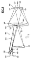
図8は、1つの可能な投影光学ユニット1の光学設計を示している。この図は、図8に互いに上下に位置し、互いからy方向に分離した5つの物体視野点から進む各場合に2つの個別ビーム845のビーム経路を示しており、これらの5つの物体視野点のうちの1つに関連付けられた2つの個別ビーム45は、各場合に、5つの物体視野点における2つの異なる照明方向に割り当てられる。これらの2つの照明方向を5つの物体視野点の各々の上側コマビームと下側コマビームとによって表している。
FIG. 8 shows the optical design of one possible projection
物体平面805から進み、個別ビーム845は、最初に第1のミラーM1によって反射され、その後、以下ではビーム経路の順序でM2、M3、M4、M5、及びM6と示す更に別のミラーによって反射される。従って、図8に記載の投影光学ユニット801は、6つの反射ミラーを有する。これらのミラーは、例えば、EUV内の波長に起因して、必要に応じて放射線833の波長に対して高い反射性を有するコーティングを担持する。投影光学ユニット801内では、互いに大幅に異なる波長を有する放射線を誘導することができ、これは、これらの光学ユニットが実質的な収色性を有するからである。従って、例えば、これらの光学ユニット内でアラインメントレーザを誘導するか又は自動焦点システムを作動させることができ、同時にこれらの作動波長とは大幅に異なる波長が照明光に用いられる。この場合、アラインメントレーザは、632.8nm、248nm、又は193nmで作動させることができ、その一方で同時に5nmと15nmの間の範囲の放射線が用いられる。
Proceeding from the
ミラーM3は凸の基本形状を有し、すなわち、凸最適合面によって説明することができる。以下の説明では、この種のミラーを略式に凸と呼び、凹最適合面によって説明することができるミラーを略式に凹と呼ぶ。凸ミラーM3は、投影光学ユニット801内で良好なペッツヴァル補正を可能にする。
The mirror M3 has a convex basic shape, that is, it can be described by a convex optimal mating surface. In the following description, this type of mirror is generally referred to as convex, and a mirror that can be described by a concave optimum mating surface is generally referred to as concave. The convex mirror M3 enables good Petzval correction within the projection
図8に記載の投影光学ユニット801の入射瞳平面は、物体平面805の前方1000mの放射線833のビーム経路内に位置する。図8に記載の投影光学ユニット801は、2000mmの構造長、すなわち、物体平面805と像平面807の間の距離を有する。
The entrance pupil plane of the projection
この場合、分離した物体視野点から進み、同じ照明方向に割り当てられた個別ビーム845は、物体視野803と第1のミラーM1との間で事実上平行な方式で投影光学ユニット801内に進む。従って、個別ビーム845の主光線は、物体平面805とミラーM1の間の放射線833のビーム経路内で互い対して事実上0°の角度を構成する。
In this case, an
5つの物体視野点の特定の照明方向に関連付けられた個別ビーム845は、隣接してミラーM3が配置された投影光学ユニット801の瞳平面847内で組み合わされる。従って、このミラーM3を瞳ミラーとも呼ぶ。瞳平面847内には、照明光ビーム束の境界を定めるための開口絞りを配置することができる。この開口絞りは、機械的かつ互換的な絞りを用いて又はそうでなければミラーM3上への対応する直接コーティングの形態で設けることができる。
The
ミラーM1からM4は、物体平面805を中間像平面849内に結像する。投影光学ユニット801の中間像側開口数は約0.2である。ミラーM1からM4は、約3.2×の縮小結像スケールを有する、投影光学ユニット801の第1の部分結像光学ユニットを形成する。下流のミラーM5及びM6は、約2.5×の縮小結像スケールを有する投影光学ユニット801の更に別の部分結像光学ユニットを形成する。ミラーM4とM5の間の放射線833のビーム経路内で、中間像平面849の上流に隣接してミラーM6内に貫通開口部851が形成され、照明又は結像放射線833は、第4のミラーM4からの反射時にこの開口部を第5のミラーM5へと通過する。更に、第5のミラーM5は、中心貫通開口部853を有し、放射線束855は、第6のミラーM6と像平面807との間でこの貫通開口部833を通過する。
The mirrors M1 to M4 image the
第6のミラーM6と共に中間像平面849からの照明又は結像放射線833を像平面807内に結像する第5のミラーM5は、第1の瞳平面847に対して共役な投影光学ユニット801の更に別の瞳平面857の近くに配置される。結像光のビーム経路内の更に別の瞳平面857は、物理的に接近可能な絞り平面が更に別の瞳平面857の位置に存在するように、第5のミラーM5と第6のミラーM6の間のビーム経路内で第5のミラーM5に空間的に隣接して位置する。この絞り平面には、瞳平面847の領域内の開口絞りに関連して上述したように、開口絞りを代替的又は追加的に同様に配置することができる。投影光学ユニット801は、瞳平面847、857の一方に中心位置方式で配置された掩蔽絞りを有する。この掩蔽絞りにより、投影ビーム経路のミラーM6、M5内の中心貫通開口部851、853に割り当てられた部分ビームが掩蔽される。従って、投影光学ユニット801の設計は、中心瞳掩蔽を有する設計とも呼ばれる。
A fifth mirror M5 for imaging the illumination or
中心物体視野点を投影光学ユニット801の入射瞳内の中心照明点にリンクする個別の個々のビーム845を中心視野点の主光線とも呼ぶ。第6のミラーM6における反射から始まる中心視野点の主光線は、像平面807とほぼ直角を成し、すなわち、投影光学ユニット801のz軸に対してほぼ平行に進む。この角度は85°よりも大きい。
The individual
像視野859は矩形である。像視野859は、x方向と平行に13mmの広がりを有する。像視野859は、y方向と平行に859mmの広がりを有する。従来技術で公知のもののような投影光学ユニットは、x方向と平行に26mm又はそれよりも大きい広がりを有する。従って、マイクロリソグラフィ投影露光装置の典型的な用途は、そのような広がりに適応される。本発明に記載のマイクロリソグラフィ投影露光装置は、x方向と平行に短い広がりを有する投影光学ユニットを同じ典型的な用途に対して用いることも可能にする。
The
像視野859は、第5のミラーM5の後方で中心に位置する。貫通開口部853の半径Rは、周辺遮光のない結像に対して以下の関係を満たさなければならない。
The
![]()
![]()
この場合、Dは、像視野859の対角距離である。dwは、ミラーM5の像平面からの自由作動距離である。この自由作動距離は、像平面807と、投影光学ユニット801の最近接ミラー、すなわち、図8に記載の実施形態ではミラーM5の利用反射面の像平面9に最も近い区画との間の距離として定められる。NAは、像側開口数である。
In this case, D is the diagonal distance of the
投影光学ユニット801の全ての6つのミラーは、回転対称関数によって説明することができない自由曲面として具現化される。ミラーM1からM6のうちの少なくとも1つがこの種の自由反射曲面を有する投影光学ユニット801の他の実施形態も同様に可能である。
All six mirrors of the projection
この種の自由曲面は、回転対称基準面から製造することができる。マイクロリソグラフィのための投影露光装置の投影光学ユニットのミラーの反射面のためのこの種の自由曲面は、US 2007−0058269 A1から公知である。 This type of free-form surface can be produced from a rotationally symmetric reference plane. Such a free-form surface for the reflecting surface of the mirror of the projection optical unit of a projection exposure apparatus for microlithography is known from US 2007-0058269 A1.
自由曲面は、次式によって数学的に説明することができる。 A free-form surface can be mathematically described by the following equation.
ここで、次式が成り立つ。 Here, the following equation holds.
![]()
![]()
Zは、点x,y(x2+y2=r)における自由曲面のサジッタである。cは、対応する非球面の頂点曲率に対応する定数である。kは、対応する非球面の円錐定数に対応する。Cjは、単項式XmYnの係数である。一般的に、c、k、及びCjの値は、投影光学ユニット801内のミラーの望ましい光学特性に基づいて決められる。単項式の次数m+nは、必要に応じて変更することができる。より高次の単項式は、より良好な像収差補正を有する投影光学ユニットの設計をもたらすことができるが、計算することがより複雑であり、m+nは、3と20超の間の値を取ることができる。
Z is the sagittal of the free-form surface at the point x, y (x 2 + y 2 = r). c is a constant corresponding to the vertex curvature of the corresponding aspherical surface. k corresponds to the conic constant of the corresponding aspheric surface. C j is the coefficient of the monomial X m Y n . In general, the values of c, k, and C j are determined based on the desired optical properties of the mirrors in the projection
また、自由曲面は、例えば、光学設計プログラム「CODE V(登録商標)」のマニュアルに説明されているゼルニケ多項式によって数学的に説明することができる。代替的に、自由曲面は、2次元スプライン面を利用して説明することができる。この説明の例は、ベジェ曲面又は不均一有理基底スプライン(NURBS)である。2次元スプライン面は、例えば、xy平面内の点のネットワークとそれに関連付けられたz値とにより、又はこれらの点とこれらの点に関連付けられた勾配とによって説明することができる。スプライン面のそれぞれの種類によっては、例えば、連続性及び微分可能性に関して固有の特性を有する多項式又は関数を用いたネットワーク点間の内挿によって完全な面が得られる。これらの関数の例は解析関数である。 The free-form surface can be mathematically described by a Zernike polynomial described in the manual of the optical design program “CODE V (registered trademark)”, for example. Alternatively, a free-form surface can be described using a two-dimensional spline surface. Examples of this description are Bezier surfaces or non-uniform rational basis splines (NURBS). A two-dimensional spline surface can be described, for example, by a network of points in the xy plane and the z value associated therewith, or by these points and the gradients associated with these points. For each type of spline surface, a complete surface can be obtained, for example, by interpolation between network points using polynomials or functions that have unique properties with respect to continuity and differentiability. Examples of these functions are analytic functions.
ミラーM1からM6は、入射するEUV照明放射線833に対して反射を最適化するために複数の反射層を担持する。反射は、ミラー面上への個別ビーム845の入射角が垂直な入射に近づく程、益々良好になる。投影光学ユニット801は、全ての個別ビーム845に対して全体として小さい反射角を有する。
The mirrors M1 to M6 carry a plurality of reflective layers in order to optimize reflection for the incident
投影光学ユニット801のミラーM1からM6の反射面の光学設計データは、下記の表から得ることができる。これらの表の最初のものは、光学構成要素の光学面及び開口絞りに関して物体平面から進めて、各場合に、頂点曲率の逆数(半径)及びビーム経路内で隣接する要素の間のz距離に対応する距離値(厚み)を明記している。第2の表は、ミラーM1からM6に対して上記に指定した自由曲面式における単項式XmYmの係数Cjを明記している。この場合、N半径は、正規化係数を表している。第2の表の後には、ミラー基準設計から進めて、それぞれのミラーが偏心(Y−偏心)及び回転(X−回転)されたマグニチュードをmmで同様に明記している。これは、上述の自由曲面設計法の場合の平行変位及び傾斜に対応する。
The optical design data of the reflecting surfaces of the mirrors M1 to M6 of the projection
この場合、変位はy方向に行われ、傾斜はx軸の回りに行われる。この場合、回転角を度で明記している。 In this case, the displacement is performed in the y direction and the tilt is performed around the x axis. In this case, the rotation angle is specified in degrees.
(表1)
(表2)
物体像オフセット、すなわち、像平面807上への物体視野803の中点の投影点と像視野859の中点との間の距離は、投影光学ユニット3の場合は208mmである。
The object image offset, that is, the distance between the projection point of the midpoint of the
604a、604b 並置部分領域
641 重ね合わせ領域
643 重ね合わせ領域内に位置する点
604a, 604b juxtaposed
Claims (20)
第2の動作状態で、前記マスクの第2の部分領域(604b、704b)が、該第2の部分領域の各点において第2の重心方向ベクトルを有する割り当てられた第2の重心方向を有する第2の放射線によって照明され、
前記第1の部分領域と該第2の部分領域(604a,704a,604b,704b)が、共通の重ね合わせ領域(641,741)を有する、
物体平面(5,805)内に反射マスクを含み、少なくとも2つの動作状態を有するマイクロ電子構成要素を生成するためのマイクロリソグラフィ投影露光装置であって、
重ね合わせ領域(641,741)の少なくとも1つの部分領域の各点で、第1の正規化重心方向ベクトルと、第2の正規化重心方向ベクトルと、マスクに対して垂直な正規化ベクトルとのスカラー三重積が、0.05よりも小さい、
ことを特徴とするマイクロリソグラフィ投影露光装置。 In the first operating state, the first partial area (604a, 704a) of the mask is assigned the first first centroid direction vector at each point of the first partial area (604a, 704a). Illuminated by a first radiation having a direction of the center of gravity;
In the second operating state, the second partial area (604b, 704b) of the mask has an assigned second centroid direction having a second centroid direction vector at each point of the second partial area. Illuminated by the second radiation,
The first partial region and the second partial region (604a, 704a, 604b, 704b) have a common overlapping region (641, 741),
A microlithographic projection exposure apparatus for producing a microelectronic component comprising a reflective mask in an object plane (5,805) and having at least two operating states,
A first normalized centroid direction vector, a second normalized centroid direction vector, and a normalization vector perpendicular to the mask at each point of at least one partial region of the overlapping region (641, 741). The scalar triple product is less than 0.05,
A microlithographic projection exposure apparatus characterized by that.
ことを特徴とする請求項1に記載のマイクロリソグラフィ投影露光装置。 At each point of at least one partial area of the overlapping area (641, 741), the first normalized centroid direction vector, the second normalized centroid direction vector, and a normal perpendicular to the mask The scalar triple product with the vector is less than 0.03,
The microlithographic projection exposure apparatus according to claim 1.
ことを特徴とする請求項1に記載のマイクロリソグラフィ投影露光装置。 At each point of at least one partial area of the overlapping area (641, 741), the first normalized centroid direction vector, the second normalized centroid direction vector, and a normal perpendicular to the mask The scalar triple product with the vector is less than 0.01,
The microlithographic projection exposure apparatus according to claim 1.
ことを特徴とする請求項1から請求項3のいずれか1項に記載のマイクロリソグラフィ投影露光装置。 The angle between the first centroid direction and the normalization vector perpendicular to the mask at each point of at least one partial region of the overlapping region (641, 741) is 3 ° or more. large,
The microlithographic projection exposure apparatus according to any one of claims 1 to 3, wherein
ことを特徴とする請求項1から請求項4のいずれか1項に記載のマイクロリソグラフィ投影露光装置。 The overlapping region (641, 741) is smaller than the first partial region (604a, 604a) and smaller than the second partial region (604b, 704b),
The microlithographic projection exposure apparatus according to claim 1, wherein the microlithographic projection exposure apparatus is characterized in that:
ことを特徴とする請求項1から請求項5のいずれか1項に記載のマイクロリソグラフィ投影露光装置。 The orientation of the reflective mask in the first operating state differs from the orientation of the mask in the second operating state by a rotation of 180 ° about an axis perpendicular to the object plane (5);
The microlithographic projection exposure apparatus according to claim 1, wherein the microlithographic projection exposure apparatus is characterized in that
前記マスクの第1の部分領域(604a、704a)が該第1の部分領域(604a、704a)の各点において第1の重心方向ベクトルを有する割り当てられた第1の重心方向を有する第1の放射線によって照明される、第1の動作状態、における反射マスクの向きが、該マスクの第2の部分領域(604b、704b)が該第2の部分領域の各点において第2の重心方向ベクトルを有する割り当てられた第2の重心方向を有する第2の放射線によって照明される、第2の動作状態、における該マスクの向きから物体平面(5)に対して垂直な軸の回りに180°の回転だけ異なり、
前記第1の部分領域と該第2の部分領域(604a,704a,604b,704b)が、共通の重ね合わせ領域(641,741)を有する、
ことを特徴とするマイクロリソグラフィ投影露光装置。 A microlithographic projection exposure apparatus for producing a microelectronic component comprising a reflective mask in an object plane (5) and having at least two operating states,
A first partial area (604a, 704a) of the mask having an assigned first centroid direction having a first centroid direction vector at each point of the first partial area (604a, 704a); is illuminated by the radiation, the first operating state, the orientation of the reflective mask in the second partial region (604b, 704b) of the mask a second centroid direction vector at each point of the second partial region 180 ° rotation about an axis perpendicular to the object plane (5) from the orientation of the mask in a second operating state , illuminated by a second radiation having an assigned second center of gravity direction Unlike only,
The first partial region and the second partial region (604a, 704a, 604b, 704b) have a common overlapping region (641, 741),
A microlithographic projection exposure apparatus characterized by that.
を含み、
前記像視野は、13mmの最大広がりを有する、
ことを特徴とする請求項1から請求項7のいずれか1項に記載のマイクロリソグラフィ投影露光装置。 A projection optical unit for imaging the object field into the image field;
Including
The image field has a maximum extent of 13 mm;
The microlithographic projection exposure apparatus according to claim 1, wherein the microlithographic projection exposure apparatus is characterized.
ことを特徴とする請求項1から請求項8のいずれか1項に記載のマイクロリソグラフィ投影露光装置。 Can be operated with radiation having a wavelength between 5 nm and 15 nm,
The microlithographic projection exposure apparatus according to claim 1, wherein the microlithographic projection exposure apparatus is characterized in that
第2の露光状況で、マスクの第2の部分領域(604b、704b)が、該第2の部分領域の各点において第2の重心ベクトルを有する第2の重心方向を有する第2の放射線によって露光され、
前記第1の部分領域と前記第2の部分領域は、共通の重ね合わせ領域(641,741)を有する、
物体平面内の反射構造担持マスクが像平面内の基板上に結像されるリソグラフィを用いてマイクロ電子構成要素を生成する方法であって、
重ね合わせ領域(641,741)の各点で、第1の正規化重心方向ベクトルと、第2の正規化重心方向ベクトルと、マスクに対して垂直な正規化ベクトルとのスカラー三重積が、0.05よりも小さい、
ことを特徴とする方法。 A first partial area (604a, 704a) is exposed in a first exposure situation with a first radiation having a first centroid direction having a first centroid direction vector at each point of the first partial area. ,
In a second exposure situation, the second partial area (604b, 704b) of the mask is caused by a second radiation having a second centroid direction having a second centroid vector at each point of the second partial area. Exposed,
The first partial region and the second partial region have a common overlapping region (641, 741).
A method of generating microelectronic components using lithography in which a reflective structure bearing mask in the object plane is imaged onto a substrate in the image plane, comprising:
The scalar triple product of the first normalized centroid direction vector, the second normalized centroid direction vector, and the normalized vector perpendicular to the mask is 0 at each point of the overlap region (641, 741). .Smaller than 05,
A method characterized by that.
ことを特徴とする請求項10に記載の方法。 A scalar triple of the first normalized centroid direction vector, the second normalized centroid direction vector, and a normalized vector perpendicular to the mask at each point of the overlap region (641, 741). Product is less than 0.03,
The method according to claim 10.
ことを特徴とする請求項10に記載の方法。 A scalar triple of the first normalized centroid direction vector, the second normalized centroid direction vector, and a normalized vector perpendicular to the mask at each point of the overlap region (641, 741). Product is less than 0.01,
The method according to claim 10.
ことを特徴とする請求項10から請求項12のいずれか1項に記載の方法。 The angle between the first centroid direction and the normalization vector perpendicular to the mask at each point of at least one partial region of the overlapping region (641, 741) is 3 ° or more. large,
13. A method according to any one of claims 10 to 12, characterized in that
ことを特徴とする請求項10から請求項13のいずれか1項に記載の方法。 The radiation has a wavelength between 5 nm and 15 nm;
14. The method according to any one of claims 10 to 13, characterized in that:
ことを特徴とする請求項10から請求項14のいずれか1項に記載の方法。 First and second exposures wherein the mask is moved through the illumination field along the first scanning direction during the first exposure and along the second scanning direction during the second exposure. Performed using a scanning process
15. A method according to any one of claims 10 to 14, characterized in that
ことを特徴とする請求項15に記載の方法。 The first and second scanning directions are parallel or anti-parallel,
The method according to claim 15.
ことを特徴とする請求項10から請求項16のいずれか1項に記載の方法。 The maximum angle between any two first centroid direction vectors (235, 335) or between any two second centroid direction vectors (235, 335) is less than 1 °,
The method according to any one of claims 10 to 16, characterized in that:
ことを特徴とする請求項10から請求項16のいずれか1項に記載の方法。 The angle between the first and second centroid vectors at each point of the overlap region is less than 1 °,
The method according to any one of claims 10 to 16, characterized in that:
ことを特徴とする請求項10から請求項16のいずれか1項に記載の方法。 At each point of the overlap region (641, 741), an angle between a plane formed by the first and second centroid direction vectors and the normalization vector perpendicular to the mask is 1 °. Smaller than,
The method according to any one of claims 10 to 16, characterized in that:
ことを特徴とする請求項10から請求項16又は請求項19のいずれか1項に記載の方法。 During the first and second exposures, the structure-bearing mask is rotated by 180 ° in the object plane (5),
20. A method according to any one of claims 10 to 16 or claim 19 characterized in that
Applications Claiming Priority (5)
| Application Number | Priority Date | Filing Date | Title |
|---|---|---|---|
| US10083608P | 2008-09-29 | 2008-09-29 | |
| DE102008042438.2 | 2008-09-29 | ||
| DE102008042438A DE102008042438B4 (en) | 2008-09-29 | 2008-09-29 | Microlithography projection exposure machine with at least two working states |
| US61/100,836 | 2008-09-29 | ||
| PCT/EP2009/006113 WO2010034382A1 (en) | 2008-09-29 | 2009-08-22 | Microlithography projection exposure apparatus having at least two operating states |
Publications (3)
| Publication Number | Publication Date |
|---|---|
| JP2012504320A JP2012504320A (en) | 2012-02-16 |
| JP2012504320A5 JP2012504320A5 (en) | 2012-10-11 |
| JP5634403B2 true JP5634403B2 (en) | 2014-12-03 |
Family
ID=41794732
Family Applications (1)
| Application Number | Title | Priority Date | Filing Date |
|---|---|---|---|
| JP2011528202A Expired - Fee Related JP5634403B2 (en) | 2008-09-29 | 2009-08-22 | Microlithography projection exposure apparatus having two or more operating states |
Country Status (7)
| Country | Link |
|---|---|
| US (1) | US9529276B2 (en) |
| JP (1) | JP5634403B2 (en) |
| KR (1) | KR101666690B1 (en) |
| CN (1) | CN102171614B (en) |
| DE (1) | DE102008042438B4 (en) |
| TW (1) | TWI483082B (en) |
| WO (1) | WO2010034382A1 (en) |
Families Citing this family (4)
| Publication number | Priority date | Publication date | Assignee | Title |
|---|---|---|---|---|
| DE102010041746A1 (en) | 2010-09-30 | 2012-04-05 | Carl Zeiss Smt Gmbh | Projection exposure apparatus of EUV microlithography and method for microlithographic exposure |
| DE102012207377A1 (en) * | 2012-05-03 | 2013-11-07 | Carl Zeiss Smt Gmbh | Illumination optics and optical system for EUV projection lithography |
| CN105573060B (en) * | 2014-10-16 | 2017-12-01 | 中芯国际集成电路制造(上海)有限公司 | EUV light source and exposure device, calibrating installation and calibration method |
| WO2016192964A1 (en) * | 2015-05-29 | 2016-12-08 | Asml Netherlands B.V. | Simulation of lithography using multiple-sampling of angular distribution of source radiation |
Family Cites Families (16)
| Publication number | Priority date | Publication date | Assignee | Title |
|---|---|---|---|---|
| US5227839A (en) * | 1991-06-24 | 1993-07-13 | Etec Systems, Inc. | Small field scanner |
| JP3711586B2 (en) | 1995-06-02 | 2005-11-02 | 株式会社ニコン | Scanning exposure equipment |
| JPH11260713A (en) * | 1998-03-12 | 1999-09-24 | Nikon Corp | Projecting exposure method and projection aligner |
| JP2000091220A (en) | 1998-09-08 | 2000-03-31 | Nikon Corp | Method and apparatus of projection exposure |
| JP2003084445A (en) * | 2001-09-13 | 2003-03-19 | Canon Inc | Scanning type exposure device and exposure method |
| WO2004079799A1 (en) * | 2003-03-05 | 2004-09-16 | Tadahiro Ohmi | Mask repeater and mask manufacturing method |
| US6833854B1 (en) * | 2003-06-12 | 2004-12-21 | Micronic Laser Systems Ab | Method for high precision printing of patterns |
| US7426076B2 (en) * | 2004-12-23 | 2008-09-16 | Asml Holding N.V. | Projection system for a lithographic apparatus |
| US7502097B2 (en) * | 2004-12-27 | 2009-03-10 | Asml Netherlands B.V. | Method and exposure apparatus for performing a tilted focus and a device manufactured accordingly |
| JP4750183B2 (en) * | 2005-05-03 | 2011-08-17 | カール・ツァイス・エスエムティー・ゲーエムベーハー | Microlithography projection optics |
| TWI451125B (en) | 2005-09-13 | 2014-09-01 | Zeiss Carl Smt Gmbh | Microlithography projection optical system, microlithographic tool comprising such an optical system, method for microlithographic production of microstructured components using such a microlithographic tool, microstructured component being produced by s |
| DE102006043251A1 (en) * | 2005-09-13 | 2007-03-15 | Carl Zeiss Smt Ag | Microlithography tool for fabrication of e.g. semiconductor chip, has projection objective with mirrors arranged to direct radiation reflected from reticle, positioned at object plane, to substrate positioned at image plane |
| JP5479890B2 (en) * | 2006-04-07 | 2014-04-23 | カール・ツァイス・エスエムティー・ゲーエムベーハー | Microlithography projection optical system, apparatus, and manufacturing method |
| US7738077B2 (en) * | 2006-07-31 | 2010-06-15 | Asml Netherlands B.V. | Patterning device utilizing sets of stepped mirrors and method of using same |
| KR20080012240A (en) * | 2006-08-02 | 2008-02-11 | 칼 짜이스 에스엠티 아게 | ILLUMINATION SYSTEM FOR A PROJECTION EXPOSURE APPARATUS WITH WAVELENGTHS <= 193 nm |
| DE102006036064A1 (en) | 2006-08-02 | 2008-02-07 | Carl Zeiss Smt Ag | Illumination system for a projection exposure apparatus with wavelengths ≦ 193 nm |
-
2008
- 2008-09-29 DE DE102008042438A patent/DE102008042438B4/en not_active Expired - Fee Related
-
2009
- 2009-08-18 TW TW098127714A patent/TWI483082B/en active
- 2009-08-22 KR KR1020117006450A patent/KR101666690B1/en active IP Right Grant
- 2009-08-22 CN CN2009801375100A patent/CN102171614B/en not_active Expired - Fee Related
- 2009-08-22 JP JP2011528202A patent/JP5634403B2/en not_active Expired - Fee Related
- 2009-08-22 WO PCT/EP2009/006113 patent/WO2010034382A1/en active Application Filing
-
2011
- 2011-03-04 US US13/040,956 patent/US9529276B2/en active Active
Also Published As
| Publication number | Publication date |
|---|---|
| CN102171614A (en) | 2011-08-31 |
| CN102171614B (en) | 2012-08-08 |
| KR20110059721A (en) | 2011-06-03 |
| DE102008042438B4 (en) | 2010-11-04 |
| WO2010034382A1 (en) | 2010-04-01 |
| KR101666690B1 (en) | 2016-10-17 |
| US9529276B2 (en) | 2016-12-27 |
| US20110200946A1 (en) | 2011-08-18 |
| TW201017344A (en) | 2010-05-01 |
| TWI483082B (en) | 2015-05-01 |
| JP2012504320A (en) | 2012-02-16 |
| DE102008042438A1 (en) | 2010-04-08 |
Similar Documents
| Publication | Publication Date | Title |
|---|---|---|
| KR102648040B1 (en) | An imaging optical unit for imaging an object field within an image field and a projection exposure apparatus comprising such imaging optical unit. | |
| JP2022176242A (en) | Projection optical unit for imaging object field into image field, and projection exposure apparatus comprising the same | |
| TWI468838B (en) | Imaging optical system and projection exposure installation for microlithography with an imaging optical system of this type | |
| JP5643755B2 (en) | Imaging optics | |
| JP2016006550A (en) | Imaging optical system | |
| US9983484B2 (en) | Illumination optical unit for EUV projection lithography | |
| CN108292032B (en) | Imaging optical unit for imaging an object field into an image field, and projection exposure apparatus comprising such an imaging optical unit | |
| US9535337B2 (en) | Imaging optics, microlithography projection exposure apparatus having same and related methods | |
| JP5946190B2 (en) | Imaging optical system and projection exposure apparatus for microlithography having this kind of imaging optical system | |
| CN108351499B (en) | Imaging optical unit for imaging an object field into an image field and projection exposure apparatus comprising such an imaging optical unit | |
| JP5634403B2 (en) | Microlithography projection exposure apparatus having two or more operating states | |
| JP7411542B2 (en) | Imaging optical unit for imaging the object field into the image field | |
| CN117441116A (en) | Imaging optical unit | |
| CN117441122A (en) | Imaging optical unit |
Legal Events
| Date | Code | Title | Description |
|---|---|---|---|
| A521 | Written amendment |
Free format text: JAPANESE INTERMEDIATE CODE: A523 Effective date: 20120821 |
|
| A621 | Written request for application examination |
Free format text: JAPANESE INTERMEDIATE CODE: A621 Effective date: 20120821 |
|
| A977 | Report on retrieval |
Free format text: JAPANESE INTERMEDIATE CODE: A971007 Effective date: 20131011 |
|
| A131 | Notification of reasons for refusal |
Free format text: JAPANESE INTERMEDIATE CODE: A131 Effective date: 20131017 |
|
| A601 | Written request for extension of time |
Free format text: JAPANESE INTERMEDIATE CODE: A601 Effective date: 20140117 |
|
| A602 | Written permission of extension of time |
Free format text: JAPANESE INTERMEDIATE CODE: A602 Effective date: 20140124 |
|
| A521 | Written amendment |
Free format text: JAPANESE INTERMEDIATE CODE: A523 Effective date: 20140212 |
|
| A01 | Written decision to grant a patent or to grant a registration (utility model) |
Free format text: JAPANESE INTERMEDIATE CODE: A01 Effective date: 20140929 |
|
| A61 | First payment of annual fees (during grant procedure) |
Free format text: JAPANESE INTERMEDIATE CODE: A61 Effective date: 20141014 |
|
| R250 | Receipt of annual fees |
Free format text: JAPANESE INTERMEDIATE CODE: R250 |
|
| LAPS | Cancellation because of no payment of annual fees |