JP5633508B2 - Piezoelectric actuator and lens barrel - Google Patents

Piezoelectric actuator and lens barrel Download PDF

Info

Publication number
JP5633508B2
JP5633508B2 JP2011507033A JP2011507033A JP5633508B2 JP 5633508 B2 JP5633508 B2 JP 5633508B2 JP 2011507033 A JP2011507033 A JP 2011507033A JP 2011507033 A JP2011507033 A JP 2011507033A JP 5633508 B2 JP5633508 B2 JP 5633508B2
Authority
JP
Japan
Prior art keywords
piezoelectric element
piezoelectric
rotor
phase
voltage
Prior art date
Legal status (The legal status is an assumption and is not a legal conclusion. Google has not performed a legal analysis and makes no representation as to the accuracy of the status listed.)
Active
Application number
JP2011507033A
Other languages
Japanese (ja)
Other versions
JPWO2010113505A1 (en
Inventor
邦宏 桑野
邦宏 桑野
容大 金満
容大 金満
Current Assignee (The listed assignees may be inaccurate. Google has not performed a legal analysis and makes no representation or warranty as to the accuracy of the list.)
Nikon Corp
Original Assignee
Nikon Corp
Priority date (The priority date is an assumption and is not a legal conclusion. Google has not performed a legal analysis and makes no representation as to the accuracy of the date listed.)
Filing date
Publication date
Application filed by Nikon Corp filed Critical Nikon Corp
Priority to JP2011507033A priority Critical patent/JP5633508B2/en
Publication of JPWO2010113505A1 publication Critical patent/JPWO2010113505A1/en
Application granted granted Critical
Publication of JP5633508B2 publication Critical patent/JP5633508B2/en
Active legal-status Critical Current
Anticipated expiration legal-status Critical

Links

Images

Classifications

    • HELECTRICITY
    • H02GENERATION; CONVERSION OR DISTRIBUTION OF ELECTRIC POWER
    • H02NELECTRIC MACHINES NOT OTHERWISE PROVIDED FOR
    • H02N2/00Electric machines in general using piezoelectric effect, electrostriction or magnetostriction
    • H02N2/02Electric machines in general using piezoelectric effect, electrostriction or magnetostriction producing linear motion, e.g. actuators; Linear positioners ; Linear motors
    • GPHYSICS
    • G02OPTICS
    • G02BOPTICAL ELEMENTS, SYSTEMS OR APPARATUS
    • G02B7/00Mountings, adjusting means, or light-tight connections, for optical elements
    • G02B7/02Mountings, adjusting means, or light-tight connections, for optical elements for lenses
    • G02B7/04Mountings, adjusting means, or light-tight connections, for optical elements for lenses with mechanism for focusing or varying magnification
    • G02B7/08Mountings, adjusting means, or light-tight connections, for optical elements for lenses with mechanism for focusing or varying magnification adapted to co-operate with a remote control mechanism
    • GPHYSICS
    • G03PHOTOGRAPHY; CINEMATOGRAPHY; ANALOGOUS TECHNIQUES USING WAVES OTHER THAN OPTICAL WAVES; ELECTROGRAPHY; HOLOGRAPHY
    • G03BAPPARATUS OR ARRANGEMENTS FOR TAKING PHOTOGRAPHS OR FOR PROJECTING OR VIEWING THEM; APPARATUS OR ARRANGEMENTS EMPLOYING ANALOGOUS TECHNIQUES USING WAVES OTHER THAN OPTICAL WAVES; ACCESSORIES THEREFOR
    • G03B13/00Viewfinders; Focusing aids for cameras; Means for focusing for cameras; Autofocus systems for cameras
    • G03B13/32Means for focusing
    • G03B13/34Power focusing
    • GPHYSICS
    • G03PHOTOGRAPHY; CINEMATOGRAPHY; ANALOGOUS TECHNIQUES USING WAVES OTHER THAN OPTICAL WAVES; ELECTROGRAPHY; HOLOGRAPHY
    • G03BAPPARATUS OR ARRANGEMENTS FOR TAKING PHOTOGRAPHS OR FOR PROJECTING OR VIEWING THEM; APPARATUS OR ARRANGEMENTS EMPLOYING ANALOGOUS TECHNIQUES USING WAVES OTHER THAN OPTICAL WAVES; ACCESSORIES THEREFOR
    • G03B3/00Focusing arrangements of general interest for cameras, projectors or printers
    • G03B3/10Power-operated focusing
    • HELECTRICITY
    • H02GENERATION; CONVERSION OR DISTRIBUTION OF ELECTRIC POWER
    • H02NELECTRIC MACHINES NOT OTHERWISE PROVIDED FOR
    • H02N2/00Electric machines in general using piezoelectric effect, electrostriction or magnetostriction
    • H02N2/0005Electric machines in general using piezoelectric effect, electrostriction or magnetostriction producing non-specific motion; Details common to machines covered by H02N2/02 - H02N2/16
    • H02N2/001Driving devices, e.g. vibrators
    • HELECTRICITY
    • H02GENERATION; CONVERSION OR DISTRIBUTION OF ELECTRIC POWER
    • H02NELECTRIC MACHINES NOT OTHERWISE PROVIDED FOR
    • H02N2/00Electric machines in general using piezoelectric effect, electrostriction or magnetostriction
    • H02N2/10Electric machines in general using piezoelectric effect, electrostriction or magnetostriction producing rotary motion, e.g. rotary motors
    • H02N2/101Electric machines in general using piezoelectric effect, electrostriction or magnetostriction producing rotary motion, e.g. rotary motors using intermittent driving, e.g. step motors
    • HELECTRICITY
    • H02GENERATION; CONVERSION OR DISTRIBUTION OF ELECTRIC POWER
    • H02NELECTRIC MACHINES NOT OTHERWISE PROVIDED FOR
    • H02N2/00Electric machines in general using piezoelectric effect, electrostriction or magnetostriction
    • H02N2/10Electric machines in general using piezoelectric effect, electrostriction or magnetostriction producing rotary motion, e.g. rotary motors
    • H02N2/14Drive circuits; Control arrangements or methods
    • HELECTRICITY
    • H04ELECTRIC COMMUNICATION TECHNIQUE
    • H04NPICTORIAL COMMUNICATION, e.g. TELEVISION
    • H04N23/00Cameras or camera modules comprising electronic image sensors; Control thereof
    • H04N23/50Constructional details
    • H04N23/55Optical parts specially adapted for electronic image sensors; Mounting thereof

Description

本発明は、圧電アクチュエータ及びレンズ鏡筒に関する。
本願は、2009年3月31日に、日本に出願された特願2009−084113号および特願2009−084114号に基づき優先権を主張し、その内容をここに援用する。
The present invention relates to a piezoelectric actuator and a lens barrel.
This application claims priority on March 31, 2009 based on Japanese Patent Application No. 2009-084113 and Japanese Patent Application No. 2009-084114 for which it applied to Japan, and uses the content here.

従来から、圧電素子を用いた圧電アクチュエータ(駆動装置)が知られている。この種の圧電アクチュエータとして、例えば、下記特許文献1は、複数の圧電素子を駆動させ、被駆動体に接触させるチップ部材を楕円運動させることで、被駆動体を駆動するものを開示している。下記特許文献1に記載の圧電アクチュエータは、XYZ直交座標系を設定した場合に、チップ部材のXZ平面に平行な楕円運動により被駆動体をX軸方向に駆動する。   Conventionally, a piezoelectric actuator (drive device) using a piezoelectric element is known. As this type of piezoelectric actuator, for example, Japanese Patent Application Laid-Open No. H10-228707 discloses a device that drives a driven body by driving a plurality of piezoelectric elements and causing an elliptical movement of a chip member that contacts the driven body. . The piezoelectric actuator described in Patent Document 1 below drives the driven body in the X-axis direction by an elliptical motion parallel to the XZ plane of the chip member when an XYZ orthogonal coordinate system is set.

特開2007−236138号公報JP 2007-236138 A

しかしながら、上記従来の圧電アクチュエータでは、異なる2方向の振動をそれぞれ独立した振動として取り出せないという課題がある。上記特許文献1では、チップ部材のX軸方向とZ軸方向との振動を、それぞれ独立した振動として取り出せないため、複数の圧電素子が互いの運動を妨げる可能性がある。複数の圧電素子が互いの運動を妨げるように駆動すると、被駆動体を駆動する圧電アクチュエータの出力が低下する。   However, the conventional piezoelectric actuator has a problem in that vibrations in two different directions cannot be extracted as independent vibrations. In Patent Document 1, since vibrations in the X-axis direction and the Z-axis direction of the chip member cannot be extracted as independent vibrations, a plurality of piezoelectric elements may interfere with each other's movement. When the plurality of piezoelectric elements are driven so as to prevent each other's movement, the output of the piezoelectric actuator that drives the driven body decreases.

本発明の態様は、異なる2方向の振動をそれぞれ独立した振動として取り出せる圧電アクチュエータ及びそれを用いたレンズ鏡筒の提供を目的とする。   An object of the present invention is to provide a piezoelectric actuator that can extract vibrations in two different directions as independent vibrations, and a lens barrel using the piezoelectric actuator.

本発明の一態様にかかる圧電アクチュエータは、複数の第1圧電素子の間に配置され、前記複数の第1圧電素子により前記複数の第1圧電素子が配置される方向と交差する第1の方向に駆動される第1の部材と、前記第1の部材に設けられた第2圧電素子と、前記第2圧電素子と接して設けられ、前記第2圧電素子により前記第1の方向と交差する第2の方向に駆動される第2の部材と、前記第2の部材により移動される第3の部材と、を備える。
本発明の別の態様にかかるレンズ鏡筒は、上記記載の圧電アクチュエータを備える。
The piezoelectric actuator according to one aspect of the present invention is disposed between the plurality of first piezoelectric element, a first direction intersecting the direction in which the plurality of first piezoelectric elements are arranged by the plurality of first piezoelectric element A first member driven by the first member, a second piezoelectric element provided on the first member, and a second piezoelectric element provided in contact with the second piezoelectric element, and intersecting the first direction by the second piezoelectric element. A second member driven in the second direction; and a third member moved by the second member.
A lens barrel according to another aspect of the present invention includes the piezoelectric actuator described above.

本発明の態様にかかる圧電アクチュエータによれば、異なる2方向の振動を、それぞれ独立した振動として取り出せる。   According to the piezoelectric actuator according to the aspect of the present invention, vibrations in two different directions can be extracted as independent vibrations.

本発明の一実施形態に係る圧電アクチュエータの正面図である。It is a front view of the piezoelectric actuator which concerns on one Embodiment of this invention. 同圧電アクチュエータの断面図である。It is sectional drawing of the piezoelectric actuator. 図1に示す圧電アクチュエータの支持駆動部の斜視図である。It is a perspective view of the support drive part of the piezoelectric actuator shown in FIG. 同支持駆動部の平面図である。It is a top view of the support drive part. 上記圧電アクチュエータの保持部及び駆動駒の組立正面図である。It is an assembly front view of the holding part and drive piece of the above-mentioned piezoelectric actuator. 同保持部及び同駆動駒の正面図である。It is a front view of the holding part and the drive piece. 上記圧電アクチュエータの回路図である。It is a circuit diagram of the piezoelectric actuator. 同圧電アクチュエータの回路図である。It is a circuit diagram of the piezoelectric actuator. 同圧電アクチュエータの電源部が供給する電圧のタイミングチャートである。It is a timing chart of the voltage which the power supply part of the same piezoelectric actuator supplies. 同圧電アクチュエータの駆動駒の動作を示す正面図である。It is a front view which shows operation | movement of the drive piece of the same piezoelectric actuator. 同駆動駒の動作を示す正面図である。It is a front view which shows operation | movement of the drive piece. 同駆動駒の動作を示す正面図である。It is a front view which shows operation | movement of the drive piece. 図1に示す圧電アクチュエータの駆動駒の先端部の変位の時間変化を示すグラフである。It is a graph which shows the time change of the displacement of the front-end | tip part of the drive piece of the piezoelectric actuator shown in FIG. 上記圧電アクチュエータを備えたレンズ鏡筒の分解斜視図である。It is a disassembled perspective view of the lens barrel provided with the said piezoelectric actuator. 同圧電アクチュエータの変形例を示す保持部及び駆動駒の正面図である。It is a front view of the holding | maintenance part and drive piece which show the modification of the same piezoelectric actuator. 同圧電アクチュエータの他の変形例を示す保持部及び駆動駒の正面図である。It is a front view of the holding | maintenance part and drive piece which show the other modification of the same piezoelectric actuator. 同圧電アクチュエータの駆動駒の先端部の変位の時間変化を示すグラフである。It is a graph which shows the time change of the displacement of the front-end | tip part of the drive piece of the same piezoelectric actuator. 同駆動駒の先端部の変位の時間変化を示すグラフである。It is a graph which shows the time change of the displacement of the front-end | tip part of the drive piece. 上記圧電アクチュエータの駆動駒の先端部、支持部、及び圧電素子の変位の時間変化を示すグラフである。It is a graph which shows the time change of the displacement of the front-end | tip part of the drive piece of the said piezoelectric actuator, a support part, and a piezoelectric element. 同圧電アクチュエータの駆動駒及びベース部の凸部の動作を示す正面図である。It is a front view which shows the operation | movement of the drive piece of the same piezoelectric actuator, and the convex part of a base part. 同圧電アクチュエータの駆動駒及びベース部の凸部の動作を示す正面図である。It is a front view which shows the operation | movement of the drive piece of the same piezoelectric actuator, and the convex part of a base part. 同圧電アクチュエータの駆動駒及びベース部の凸部の動作を示す正面図である。It is a front view which shows the operation | movement of the drive piece of the same piezoelectric actuator, and the convex part of a base part. 同圧電アクチュエータの駆動駒及びベース部の凸部の動作を示す正面図である。It is a front view which shows the operation | movement of the drive piece of the same piezoelectric actuator, and the convex part of a base part.

本発明の一実施形態に係る圧電アクチュエータを、図面を参照しながら以下に説明する。本実施形態の圧電アクチュエータ(駆動装置)1は、例えばロータ等の第1部分と駆動駒等の第2部分とを相対的に変位させる相対駆動を行うことで、カメラのレンズ鏡筒等の光学機器や電子機器を駆動するためのものである。   A piezoelectric actuator according to an embodiment of the present invention will be described below with reference to the drawings. The piezoelectric actuator (driving device) 1 of the present embodiment performs relative driving to relatively displace a first portion such as a rotor and a second portion such as a driving piece, so that an optical lens such as a lens barrel of a camera is obtained. This is for driving devices and electronic devices.

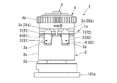
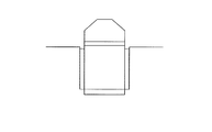
図1は本実施形態の圧電アクチュエータ1の正面図であり、図2はその断面図である。
図1及び図2に示すように、圧電アクチュエータ1は、複数の保持部2aが設けられたベース部(第4の部材)2と、保持部2aに保持された駆動駒3と、駆動駒3に隣接して配置されたロータ(第3の部材)4と、ベース部2に挿通された支持軸5と、を備えている。
FIG. 1 is a front view of the piezoelectric actuator 1 of the present embodiment, and FIG. 2 is a sectional view thereof.
As shown in FIGS. 1 and 2, the piezoelectric actuator 1 includes a base part (fourth member) 2 provided with a plurality of holding parts 2a, a driving piece 3 held by the holding part 2a, and a driving piece 3 A rotor (third member) 4 disposed adjacent to the base portion 2 and a support shaft 5 inserted through the base portion 2.

ベース部2は、例えばステンレス鋼等の金属材料により中空円筒状に形成され、支持軸5が挿通されることで、支持軸5を囲むように設けられている。
ロータ4は、ベアリング5aを介して支持軸5によって支持(軸支)され、支持軸5を回転軸として回転自在に設けられている。ロータ4の外周面には、例えばカメラのレンズ鏡筒等を駆動するための歯車4aが形成されている。ロータ4のベース部2側の面は、複数の駆動駒3によって支持されている。
The base portion 2 is formed in a hollow cylindrical shape from a metal material such as stainless steel, and is provided so as to surround the support shaft 5 by inserting the support shaft 5.
The rotor 4 is supported (supported) by a support shaft 5 via a bearing 5a, and is provided rotatably about the support shaft 5 as a rotation shaft. On the outer peripheral surface of the rotor 4, for example, a gear 4a for driving a lens barrel of a camera is formed. The surface of the rotor 4 on the base portion 2 side is supported by a plurality of driving pieces 3.

ベース部2の一方の端部は、例えば不図示のボルト等により、取付部101aに固定されている。ベース部2の取付部101aに対向する面の中央部には、凹部2bが形成されている。凹部2bには、支持軸5の基端に形成された拡径部5aが挿入(嵌入)されている。この状態でベース部2が取付部101aに固定されることで、支持軸5がベース部2及び取付部101aに固定されている。   One end portion of the base portion 2 is fixed to the mounting portion 101a with, for example, a bolt (not shown). A concave portion 2b is formed in the central portion of the surface of the base portion 2 facing the mounting portion 101a. An enlarged diameter portion 5 a formed at the base end of the support shaft 5 is inserted (inserted) into the recess 2 b. In this state, the base portion 2 is fixed to the attachment portion 101a, whereby the support shaft 5 is fixed to the base portion 2 and the attachment portion 101a.

ベース部2の他方の端部には、凹状の保持部2aが、ベース部2の周方向、すなわちロータ4の回転方向Rに、複数設けられている。保持部2aは、駆動駒3を支持軸5に垂直でロータ4の回転方向Rに沿う方向(第2の方向)の両側から支持するとともに、駆動駒3を支持軸5に平行な方向(第1の方向)に駆動可能に保持している。   At the other end of the base portion 2, a plurality of concave holding portions 2 a are provided in the circumferential direction of the base portion 2, that is, in the rotation direction R of the rotor 4. The holding portion 2a supports the drive piece 3 from both sides in a direction (second direction) perpendicular to the support shaft 5 and along the rotation direction R of the rotor 4 (second direction), and also supports the drive piece 3 in a direction parallel to the support shaft 5 (first direction). 1 direction).

図2に示すように、ベース部2の側面2cは、支持軸5と略平行に設けられている。側面2cの保持部2aと取付部101a側の端部との間には、取付部101aから保持部2aへの振動の伝達を抑制する振動抑制部としての溝部2dが形成されている。すなわち、溝部2dは、支持軸5に略垂直でかつロータ4の回転方向Rに沿う方向(第2の方向)と交差するベース部2の側面2cに設けられている。溝部2dは、ベース部2の周方向に連続的に設けられ、保持部2aと取付部101a側の端部との中間よりも取付部101a側の端部に近い位置に設けられている。   As shown in FIG. 2, the side surface 2 c of the base portion 2 is provided substantially parallel to the support shaft 5. Between the holding portion 2a of the side surface 2c and the end portion on the mounting portion 101a side, a groove portion 2d is formed as a vibration suppressing portion that suppresses transmission of vibration from the mounting portion 101a to the holding portion 2a. That is, the groove 2 d is provided on the side surface 2 c of the base 2 that is substantially perpendicular to the support shaft 5 and intersects the direction (second direction) along the rotation direction R of the rotor 4. The groove portion 2d is provided continuously in the circumferential direction of the base portion 2, and is provided at a position closer to the end portion on the attachment portion 101a side than the middle between the holding portion 2a and the end portion on the attachment portion 101a side.

溝部2dの深さd1は、例えばベース部2の半径r1の40%以上かつ80%以下の範囲である。上記数値は一例であってこれに限定されない。溝部2dの深さd1は、例えば、ベース部2の半径r1の10,20,30,40,50,60,70,80,又は90%にできる。また、支持軸5に平行な方向(第1の方向)の溝部2dの幅w1は、ベース部2の振動の振幅よりも大きく、後述する第1圧電素子6、第2圧電素子7、駆動駒3、及びベース部2からなる支持駆動部(構造部)1aの共振振動の振幅よりも大きくなるように形成されている。一例において、溝部2dの幅w1は、ベース部2の半径よりも短くできる。   The depth d1 of the groove 2d is, for example, in the range of 40% to 80% of the radius r1 of the base 2. The above numerical value is an example, and the present invention is not limited to this. The depth d1 of the groove 2d can be, for example, 10, 20, 30, 40, 50, 60, 70, 80, or 90% of the radius r1 of the base 2. Further, the width w1 of the groove 2d in the direction parallel to the support shaft 5 (first direction) is larger than the amplitude of vibration of the base 2, and the first piezoelectric element 6, the second piezoelectric element 7, and the driving piece, which will be described later. 3 and the support drive part (structure part) 1a comprising the base part 2 are formed so as to be larger than the amplitude of resonance vibration. In one example, the width w1 of the groove 2d can be shorter than the radius of the base 2.

図2に示すように、ベース部2と支持軸5との間には、取付部101aから保持部2aへの振動を抑制するための間隙(振動抑制部)2eが設けられている。間隙2eは、支持軸5と平行な方向に、ベース部2の保持部2a側の端部から溝部2dの取付部101a側の縁と同様の位置まで設けられている。また、間隙2eの幅w2は、溝部2dの幅w1と同様に、ベース部2の振動の振幅よりも大きく、後述する支持駆動部1aの共振振動の振幅よりも大きくなるように形成されている。   As shown in FIG. 2, a gap (vibration suppressing portion) 2 e for suppressing vibration from the mounting portion 101 a to the holding portion 2 a is provided between the base portion 2 and the support shaft 5. The gap 2e is provided in the direction parallel to the support shaft 5 from the end portion on the holding portion 2a side of the base portion 2 to the same position as the edge on the mounting portion 101a side of the groove portion 2d. Similarly to the width w1 of the groove 2d, the width w2 of the gap 2e is formed to be larger than the amplitude of vibration of the base portion 2 and larger than the amplitude of resonance vibration of the support driving portion 1a described later. .

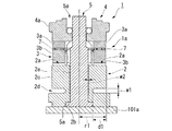
図3は図1に示す圧電アクチュエータ1の支持駆動部1aの斜視図であり、図4はその平面図である。
図3及び図4に示すように、駆動駒3は、断面が山形の六角柱形状を有する先端部(第2の部材)3aと、略直方体形状を有する基部(第1の部材)3bと、を有している。先端部3aは、例えばステンレス鋼等により形成されている。基部3bは、例えば軽金属合金等により形成されている。基部3bは、保持部2aによって、支持軸5と平行な方向に駆動可能に支持されている。先端部3aは、保持部2aから突出してロータ4を支持する。
先端部3aは、接触面S1に対して傾斜した傾斜面S2、S3が設けられている。傾斜面S2、S3は、ロータ4が回転駆動される方向と交差する方向に沿って設けられている。傾斜面S2、S3は、先端部3aのロータ4と接触する接触面S1に平行な断面積が、ロータ4に近づくほど小さい先細状の形状になるように、先端部3aの接触面S1と連続して設けられている。すなわち、先端部3aは、ロータ4に接触する接触面S1の面積が基部3b側の底面の面積よりも小さくなる先細状の形状となっている。傾斜面S2、S3は、凹状又は凸状の曲面であってもよい。
3 is a perspective view of the support drive unit 1a of the piezoelectric actuator 1 shown in FIG. 1, and FIG. 4 is a plan view thereof.
As shown in FIGS. 3 and 4, the driving piece 3 includes a tip portion (second member) 3 a having a hexagonal column shape having a mountain-shaped cross section, and a base portion (first member) 3 b having a substantially rectangular parallelepiped shape, have. The tip portion 3a is formed of, for example, stainless steel. The base 3b is made of, for example, a light metal alloy. The base portion 3b is supported by the holding portion 2a so as to be drivable in a direction parallel to the support shaft 5. The tip portion 3a supports the rotor 4 by projecting from the holding portion 2a.
The tip 3a is provided with inclined surfaces S2 and S3 that are inclined with respect to the contact surface S1. The inclined surfaces S2 and S3 are provided along a direction that intersects the direction in which the rotor 4 is rotationally driven. The inclined surfaces S2 and S3 are continuous with the contact surface S1 of the tip portion 3a so that the cross-sectional area parallel to the contact surface S1 that contacts the rotor 4 of the tip portion 3a becomes smaller as the rotor 4 approaches. Is provided. That is, the tip 3a has a tapered shape in which the area of the contact surface S1 that contacts the rotor 4 is smaller than the area of the bottom surface on the base 3b side. The inclined surfaces S2 and S3 may be concave or convex curved surfaces.

図4に示すように、駆動駒3の幅w3方向(第2の方向)には、駆動駒3の基部3bを幅w3方向の両側から挟みこむ一対の第1圧電素子6,6が、二対設けられている。駆動駒3の幅方向w3は、支持軸5に垂直でロータ4の回転方向Rに沿う方向であって、ベース部2の平面視における中心線CLと略垂直な方向である。第1圧電素子6は、保持部2aの深さd2方向に沿って延びる細長い長方形状の形状に形成され、基部3bと保持部2aとの間に挟持されている。これにより、第1圧電素子6は、ベース部2に設けられた溝部2d(図1及び図2参照)とロータ4との間に配置されている。   As shown in FIG. 4, in the width w3 direction (second direction) of the drive piece 3, there are two pairs of first piezoelectric elements 6 and 6 sandwiching the base 3b of the drive piece 3 from both sides in the width w3 direction. Pairs are provided. The width direction w3 of the drive piece 3 is a direction perpendicular to the support shaft 5 and along the rotation direction R of the rotor 4, and is substantially perpendicular to the center line CL in plan view of the base portion 2. The first piezoelectric element 6 is formed in an elongated rectangular shape extending along the depth d2 direction of the holding portion 2a, and is sandwiched between the base portion 3b and the holding portion 2a. Thereby, the first piezoelectric element 6 is disposed between the groove 4 d (see FIGS. 1 and 2) provided in the base portion 2 and the rotor 4.

第1圧電素子6は、例えば導電性の接着剤により、駆動駒3の基部3bと保持部2aとに接着されている。また、ベース部2の中心を通る中心線CLと略平行な駆動駒3の奥行p1方向に配置された2つの第1圧電素子6,6は、互いに略平行になっている。各々の第1圧電素子6の形状及び寸法は、全て略等しくなっている。   The first piezoelectric element 6 is bonded to the base portion 3b and the holding portion 2a of the driving piece 3 with, for example, a conductive adhesive. The two first piezoelectric elements 6 and 6 arranged in the depth p1 direction of the driving piece 3 substantially parallel to the center line CL passing through the center of the base portion 2 are substantially parallel to each other. All the first piezoelectric elements 6 have substantially the same shape and size.

図3に示すように、駆動駒3の基部3bと先端部3aとの間には、一対の第2圧電素子7,7が、互いに略平行に設けられている。第2圧電素子7は、駆動駒3の幅w3方向と略平行に延びる細長い長方形状に形成されている。第2圧電素子7は、先端部3aの底面と基部3bの上面との間に挟持され、例えば導電性の接着剤により、先端部3aの底面と基部3bの上面とに接着されている。各々の第2圧電素子7の形状及び寸法は、全て略等しくなっている。   As shown in FIG. 3, a pair of second piezoelectric elements 7 and 7 are provided substantially parallel to each other between the base 3 b and the tip 3 a of the drive piece 3. The second piezoelectric element 7 is formed in an elongated rectangular shape extending substantially parallel to the direction of the width w3 of the driving piece 3. The second piezoelectric element 7 is sandwiched between the bottom surface of the tip portion 3a and the top surface of the base portion 3b, and is bonded to the bottom surface of the tip portion 3a and the top surface of the base portion 3b by, for example, a conductive adhesive. All the second piezoelectric elements 7 have substantially the same shape and size.

第1圧電素子6及び第2圧電素子7は、例えばチタン酸ジルコン酸鉛(PZT)により形成され、その振動モードは厚み滑り振動である。すなわち、第1圧電素子6は、駆動駒3を、支持軸5と略平行な保持部2aの深さd2方向に、ベース部2に対して相対的に駆動させる。第2圧電素子7は、駆動駒3の先端部3aを駆動駒3の幅w3方向(第3の方向)に、基部3b及びベース部2に対して相対的に駆動させる。すなわち、本実施形態では、第1圧電素子6が駆動駒3を挟み込む方向(第2の方向)と、第2圧電素子7が駆動駒3の先端部3aを駆動させる方向(第3の方向)とが、略等しくなっている。   The first piezoelectric element 6 and the second piezoelectric element 7 are made of, for example, lead zirconate titanate (PZT), and the vibration mode is thickness shear vibration. That is, the first piezoelectric element 6 drives the drive piece 3 relative to the base portion 2 in the direction of the depth d2 of the holding portion 2a substantially parallel to the support shaft 5. The second piezoelectric element 7 drives the tip 3 a of the drive piece 3 in the width w3 direction (third direction) of the drive piece 3 relative to the base 3 b and the base 2. That is, in the present embodiment, the direction in which the first piezoelectric element 6 sandwiches the drive piece 3 (second direction), and the direction in which the second piezoelectric element 7 drives the tip 3a of the drive piece 3 (third direction). Are substantially equal.

これら複数の第1圧電素子6、第2圧電素子7、駆動駒3、及びベース部2により、ロータ4を支持し、かつロータ4を駆動駒3及びベース部2と相対的に駆動させる支持駆動部1aが構成されている。   The plurality of first piezoelectric elements 6, second piezoelectric elements 7, drive piece 3, and base portion 2 support the rotor 4 and drive the rotor 4 relative to the drive piece 3 and the base portion 2. Part 1a is configured.

図3に示すように、保持部2aは、ベース部2の端部に設けられている。ベース部2には、王冠状の凹凸が形成されている。図4に示すように、保持部2aは、ベース部2の周方向の略60°毎に、均等に形成されている。保持部2aは、平面視でベース部2の中心を通る中心線CLと略平行に設けられた一対の支持面2f,2fを備えている。支持面2fは、駆動駒3の基部3bを、ベース部2の中心線CLと略垂直な保持部2aの幅w4方向(第2の方向)の両側から、一対の第1圧電素子6,6を介して挟み込むように保持している。換言すると、ベース部2は、軸方向の一端側に設けられた周壁を有する。周壁は、周方向に間隔を空けて配された複数の溝(保持部2a)と、隣り合う溝の間に各々が配された複数の突起(凸部2h,2i、第4の部材)とを有する。本実施形態において、周壁は、実質的等間隔(約60°ピッチ)に配された6つの溝(保持部2a)と、実質的等間隔(約60°ピッチ)に配された6つの突起(凸部2h、2i)とを有する。各溝(保持部2a)は、放射方向に沿った中心線CLと、中心線CLに実質的に平行な2つの支持面(突起2h,2iの周方向の壁面2f)とを含む。突起は、外方面に比べて内方面が狭い。本実施形態において、突起は、径方向内方に向かって徐々に幅が狭くなる横断面を有する。各溝(保持部2a)に駆動駒3が配される。隣り合う突起(凸部2h、2i)の間に第1圧電素子6を介して駆動駒3が挟まれかつ支持される。他の実施形態において、周壁は、約60°以外のピッチに配された複数の溝を有することができ、また、約60°以外のピッチに配された複数の突起を有することができる。   As shown in FIG. 3, the holding portion 2 a is provided at the end of the base portion 2. The base portion 2 is formed with crown-shaped irregularities. As shown in FIG. 4, the holding | maintenance part 2a is formed equally about every 60 degrees of the circumferential direction of the base part 2. As shown in FIG. The holding portion 2a includes a pair of support surfaces 2f and 2f provided substantially parallel to a center line CL passing through the center of the base portion 2 in plan view. The support surface 2f allows the base 3b of the drive piece 3 to be connected to the pair of first piezoelectric elements 6 and 6 from both sides in the width w4 direction (second direction) of the holding portion 2a substantially perpendicular to the center line CL of the base portion 2. It is held so as to be sandwiched through. In other words, the base portion 2 has a peripheral wall provided on one end side in the axial direction. The peripheral wall includes a plurality of grooves (holding portions 2a) arranged at intervals in the circumferential direction, and a plurality of protrusions (convex portions 2h, 2i, a fourth member) each arranged between adjacent grooves. Have In the present embodiment, the peripheral wall has six grooves (holding portions 2a) arranged at substantially equal intervals (approximately 60 ° pitch) and six protrusions (approximately 60 ° pitch) disposed at substantially equal intervals (about 60 ° pitch). Convex portions 2h, 2i). Each groove (holding portion 2a) includes a center line CL along the radial direction, and two support surfaces (wall surfaces 2f in the circumferential direction of the protrusions 2h and 2i) substantially parallel to the center line CL. The protrusion has a narrow inner surface compared to the outer surface. In this embodiment, the protrusion has a cross section whose width gradually decreases inward in the radial direction. A driving piece 3 is disposed in each groove (holding portion 2a). The drive piece 3 is sandwiched and supported via the first piezoelectric element 6 between adjacent protrusions (convex portions 2h, 2i). In other embodiments, the peripheral wall can have a plurality of grooves disposed at a pitch other than about 60 °, and can have a plurality of protrusions disposed at a pitch other than about 60 °.

図5Aは保持部2a及び駆動駒3を拡大した組立正面図であり、図5Bは保持部2a及び駆動駒3を拡大した正面図である。
図5A及び図5Bに示すように、ベース部2に設けられた凹状の保持部2aの支持面2fは、図2に示す支持軸5と略平行な保持部2aの深さd2方向(第1の方向)に対して、傾斜させて設けられている。
FIG. 5A is an enlarged front view of the holding unit 2a and the driving piece 3, and FIG. 5B is an enlarged front view of the holding unit 2a and the driving piece 3.
As shown in FIGS. 5A and 5B, the support surface 2f of the concave holding portion 2a provided in the base portion 2 is formed in the depth d2 direction of the holding portion 2a substantially parallel to the support shaft 5 shown in FIG. With respect to the direction).

支持面2fは、図1に示す駆動駒3の先端部3aに支持されたロータ4からの距離が遠ざかるほど、対向する支持面2f,2f同士の間隔が漸次狭くなるように傾斜している。換言すると、保持部2aは、底面2gに近づくほど、幅w4が狭くなっている。保持部2aの深さd2方向に対する支持面2fの傾斜角度αは、各部材の寸法や公差等の関係から、2°以上6°以下であることが好ましい。本実施形態において、支持面の傾斜角度αは4°である。   The support surface 2f is inclined so that the distance between the opposed support surfaces 2f and 2f gradually decreases as the distance from the rotor 4 supported by the tip 3a of the drive piece 3 shown in FIG. 1 increases. In other words, the width w4 of the holding portion 2a becomes narrower as it approaches the bottom surface 2g. The inclination angle α of the support surface 2f with respect to the direction of the depth d2 of the holding portion 2a is preferably 2 ° or more and 6 ° or less in consideration of the dimensions and tolerances of each member. In the present embodiment, the inclination angle α of the support surface is 4 °.

また、図5A及び図5Bに示すように、支持面2fに対向する駆動駒3の基部3bの側面3cは、支持面2fと同様に、支持軸5と略平行な駆動駒3の高さh1方向(第1の方向)に対して、傾斜させて設けられている。これにより、駆動駒3の基部3bの側面3cは、支持面2fと略平行に設けられている。ここで、基部3bの保持部2aの底面2g側の端部における基部3b及び一対の第1圧電素子6,6の幅w5は、保持部2aの開口部における幅w4よりも小さく、保持部2aの深さd2方向の途中における幅w4’よりも大きくなっている。   Further, as shown in FIGS. 5A and 5B, the side surface 3c of the base 3b of the drive piece 3 facing the support surface 2f is similar to the support surface 2f in the height h1 of the drive piece 3 substantially parallel to the support shaft 5. It is inclined with respect to the direction (first direction). Thereby, the side surface 3c of the base 3b of the drive piece 3 is provided substantially parallel to the support surface 2f. Here, the width w5 of the base 3b and the pair of first piezoelectric elements 6 and 6 at the end on the bottom surface 2g side of the holding portion 2a of the base 3b is smaller than the width w4 at the opening of the holding portion 2a, and the holding portion 2a. Is larger than the width w4 ′ in the middle of the depth d2 direction.

そのため、駆動駒3の基部3b及び一対の第1圧電素子6,6を、保持部2aに保持させると、図5Bに示すように、駆動駒3の底面3dと保持部2aの底面2gとが離間した状態で、基部3bが、保持部2aの幅w4方向の両側から、一対の第1圧電素子6,6を介して支持面2fによって支持される。すなわち、支持面2fは、駆動駒3を、保持部2aの幅w4方向(第2の方向)の両側から支持するとともに、支持軸5と略平行な保持部2aの深さd2方向(第1の方向)において位置決めをするように、深さd2方向に対して、傾斜させて設けられている。   Therefore, when the base 3b of the drive piece 3 and the pair of first piezoelectric elements 6 and 6 are held by the holding part 2a, as shown in FIG. 5B, the bottom face 3d of the drive piece 3 and the bottom face 2g of the holding part 2a are formed. In a separated state, the base portion 3b is supported by the support surface 2f via the pair of first piezoelectric elements 6 and 6 from both sides in the width w4 direction of the holding portion 2a. That is, the support surface 2f supports the drive piece 3 from both sides in the width w4 direction (second direction) of the holding portion 2a, and also in the depth d2 direction (first direction) of the holding portion 2a substantially parallel to the support shaft 5. In the direction of the depth d2).

図3及び図4に示すように、本実施形態の駆動駒3は、先端部3aと基部3bとの間に一対の第2圧電素子7,7を備え、基部3bの側面に一対の第1圧電素子6,6を二対備えている。圧電アクチュエータ1は、この駆動駒3及び二対の第1圧電素子6を3つ備えた駆動駒3の組を、第1組及び第2組の二組備えている。第1組の駆動駒31と第2組の駆動駒32とは、同一の円周上に配置されている。また、各々の組の駆動駒31,32は、ロータ4の回転方向Rに、それぞれ均等に配置されている。異なる組の駆動駒31,32は、回転方向Rに、交互に(順番に)配置されている。
また、各々の組の駆動駒31,32は、初期状態において全ての接触面S11,S12がロータ4に接触するように、ベース部2から接触面S11,S12までの高さが均一に設けられている。
以下の説明では、異なる組の駆動駒31,32を区別しない場合には、これらの符号を駆動駒3とし、両者をまとめて説明する。先端部31a,32a、基部31b,32b、接触面S11,S12等についても同様に、先端部3a、基部3b、接触面S1等として説明する。
As shown in FIGS. 3 and 4, the drive piece 3 of the present embodiment includes a pair of second piezoelectric elements 7 and 7 between the tip portion 3a and the base portion 3b, and a pair of first piezoelectric elements on the side surface of the base portion 3b. Two pairs of piezoelectric elements 6 and 6 are provided. The piezoelectric actuator 1 includes two sets of first and second sets of driving pieces 3 including the driving piece 3 and three pairs of first piezoelectric elements 6. The first set of drive pieces 31 and the second set of drive pieces 32 are arranged on the same circumference. Further, each set of drive pieces 31 and 32 is equally arranged in the rotation direction R of the rotor 4. Different sets of drive pieces 31 and 32 are arranged alternately (in order) in the rotation direction R.
Further, each set of driving pieces 31 and 32 is provided with a uniform height from the base portion 2 to the contact surfaces S11 and S12 so that all the contact surfaces S11 and S12 are in contact with the rotor 4 in the initial state. ing.
In the following description, when different sets of drive pieces 31 and 32 are not distinguished, these symbols are referred to as drive pieces 3 and both will be described together. Similarly, the tip portions 31a, 32a, the base portions 31b, 32b, the contact surfaces S11, S12, and the like will be described as the tip portion 3a, the base portion 3b, the contact surface S1, and the like.

図6Aは第1圧電素子6の模式的な配線図であり、図6Bは第2圧電素子7の模式的な配線図である。
図6A及び図6Bに示すように、本実施形態の圧電アクチュエータ1は、第1圧電素子6及び第2圧電素子7の各々に電圧を供給する電源部10を備えている。電源部10は、図3及び図4に示す第1組及び第2組のそれぞれの駆動駒31,32の先端部31a,32aが、順次、図1及び図2に示すロータ4との接触、ロータ4の回転方向Rへの送り、ロータ4からの離間、ロータ4の回転方向Rと逆方向の戻り、を繰り返すように、第1圧電素子6及び第2圧電素子7に電圧を供給する。
FIG. 6A is a schematic wiring diagram of the first piezoelectric element 6, and FIG. 6B is a schematic wiring diagram of the second piezoelectric element 7.
As shown in FIGS. 6A and 6B, the piezoelectric actuator 1 of this embodiment includes a power supply unit 10 that supplies a voltage to each of the first piezoelectric element 6 and the second piezoelectric element 7. In the power supply unit 10, the tip portions 31a and 32a of the drive pieces 31 and 32 in the first set and the second set shown in FIGS. 3 and 4 are in contact with the rotor 4 shown in FIGS. A voltage is supplied to the first piezoelectric element 6 and the second piezoelectric element 7 so as to repeat feeding in the rotation direction R of the rotor 4, separation from the rotor 4, and return in the direction opposite to the rotation direction R of the rotor 4.

図6Aに示すように、第1組の駆動駒31の各々が備える第1圧電素子61は、第1配線11を介して電源部10の第1端子T1に接続されている。第2組の駆動駒32の各々が備える第1圧電素子62は、第2配線12を介して電源部10の第2端子T2に接続されている。
図6Bに示すように、第1組の駆動駒31の各々が備える第2圧電素子71は、第3配線13を介して電源部10の第3端子T3に接続されている。第2組の駆動駒32の各々が備える第2圧電素子72は、第4配線14を介して電源部10の第4端子T4に接続されている。
また、図6A及び図6Bにおいて、図示は省略するが、駆動駒31,32の基部31b,32bは接地されている。
As shown in FIG. 6A, the first piezoelectric element 61 included in each of the first set of driving pieces 31 is connected to the first terminal T <b> 1 of the power supply unit 10 via the first wiring 11. The first piezoelectric element 62 provided in each of the second set of driving pieces 32 is connected to the second terminal T <b> 2 of the power supply unit 10 via the second wiring 12.
As shown in FIG. 6B, the second piezoelectric element 71 included in each of the first set of driving pieces 31 is connected to the third terminal T <b> 3 of the power supply unit 10 via the third wiring 13. The second piezoelectric element 72 included in each of the second set of driving pieces 32 is connected to the fourth terminal T4 of the power supply unit 10 via the fourth wiring 14.
6A and 6B, although not shown, the base portions 31b and 32b of the drive pieces 31 and 32 are grounded.

図7は、電源部10が各端子T1,T2,T3,T4に発生させる電圧のタイミングチャートの一例である。
図7に示すように、電源部10は、第1端子T1に、Phase1〜Phase2の間では−1.0Vの電圧を発生させ、Phase3〜Phase7の5Phaseでは1.0Vの電圧を発生させ、Phase8〜Phase10の3Phaseでは−1.0Vの電圧を発生させる。以降のPhaseでは、1.0Vの電圧を5Phaseの間発生させ、−1.0Vの電圧を3Phaseの間発生させることを繰り返す。すなわち、電源部10は、第1端子に8Phaseを一周期とする電圧を発生させる。
FIG. 7 is an example of a timing chart of voltages generated by the power supply unit 10 at the terminals T1, T2, T3, and T4.
As shown in FIG. 7, the power supply unit 10 generates a voltage of −1.0 V between Phase 1 and Phase 2 at the first terminal T 1, and generates a voltage of 1.0 V in 5 Phases of Phase 3 to Phase 7. -In Phase 3 of Phase 10, a voltage of -1.0 V is generated. In subsequent Phases, a voltage of 1.0 V is generated for 5 Phases, and a voltage of -1.0 V is generated for 3 Phases repeatedly. That is, the power supply unit 10 generates a voltage having 8 Phase as one cycle at the first terminal.

電源部10は、第2端子T2に、第1端子T1に発生させる電圧と180°の位相差を有し、第1端子T1に発生させる電圧と同様の8Phaseを一周期とする電圧を発生させる。すなわち、第1端子に発生する電圧と、第2端子に発生する電圧とは、半周期分の4Phaseの位相差を有している。   The power supply unit 10 causes the second terminal T2 to generate a voltage having a phase difference of 180 ° from the voltage generated at the first terminal T1 and having the same 8 Phase as the voltage generated at the first terminal T1 as one cycle. . That is, the voltage generated at the first terminal and the voltage generated at the second terminal have a phase difference of 4 Phases corresponding to a half cycle.

電源部10は、第3端子T3に、Phase1において発生させる電圧を0Vに維持し、Phase2において−3.0Vの電圧を発生させ、Phase3〜Phase8までの各Phaseにおいて電圧を1.0Vずつ増加させる。以降のPhaseでは、このPhase1〜Phase8の電圧の発生パターンを繰り返す。すなわち、電源部10は、第3端子T3に、8Phaseを一周期とする電圧を発生させる。   The power supply unit 10 maintains the voltage generated in Phase 1 at the third terminal T3 at 0 V, generates a voltage of -3.0 V in Phase 2, and increases the voltage by 1.0 V in each Phase from Phase 3 to Phase 8. . In subsequent phases, the voltage generation pattern of Phase 1 to Phase 8 is repeated. That is, the power supply unit 10 generates a voltage having 8 Phase as one cycle at the third terminal T3.

電源部10は、第4端子T4に、第3端子T3に発生させる電圧と180°の位相差を有し、第3端子T3に発生させる電圧と同様の8Phaseを一周期とする電圧を発生させる。すなわち、第3端子に発生する電圧と、第4端子に発生する電圧とは、半周期分の4Phaseの位相差を有している。   The power supply unit 10 causes the fourth terminal T4 to generate a voltage having a phase difference of 180 ° from the voltage to be generated at the third terminal T3 and having the same 8 Phase as the voltage to be generated at the third terminal T3. . That is, the voltage generated at the third terminal and the voltage generated at the fourth terminal have a phase difference of 4 Phase corresponding to a half cycle.

本実施形態では、電源部10が第1圧電素子6及び第2圧電素子7に供給する電圧の周波数は、第1圧電素子6、第2圧電素子7、駆動駒3、及びベース部2からなる支持駆動部(構造部)1aの共振振動の振動数と、略等しくなっている。   In the present embodiment, the frequency of the voltage supplied from the power supply unit 10 to the first piezoelectric element 6 and the second piezoelectric element 7 includes the first piezoelectric element 6, the second piezoelectric element 7, the driving piece 3, and the base part 2. The frequency of the resonance vibration of the support drive part (structure part) 1a is substantially equal.

次に、本実施形態の圧電アクチュエータ1の作用について、図8〜図11を用いて以下に説明する。
図8〜図10は、第1組と第2組の駆動駒31,32の動作と、ロータ4の動作とを示す拡大正面図である。
図11は、第1組及び第2組の駆動駒32の先端部32aの各軸方向の変位と、時間tとの関係を示すグラフである。図11(a)及び図11(b)において、Y軸方向におけるロータ4との接触位置y1は、破線で表わされる。
Next, the operation of the piezoelectric actuator 1 of the present embodiment will be described below with reference to FIGS.
8 to 10 are enlarged front views showing the operation of the first and second sets of drive pieces 31 and 32 and the operation of the rotor 4.
FIG. 11 is a graph showing the relationship between the displacements in the respective axial directions of the tip end portions 32a of the first and second sets of driving pieces 32 and time t. In FIG. 11A and FIG. 11B, the contact position y1 with the rotor 4 in the Y-axis direction is represented by a broken line.

図8(a)〜図10(a)では、ロータ4の回転方向Rに沿う第1組の駆動駒3の幅w31方向(第2の方向)をX1方向とし、支持軸5に平行な方向(第1の方向)をY方向とする直交座標系を用いて説明する。図8(b)〜図10(b)では、ロータ4の回転方向Rに沿う第2組の駆動駒32の幅w32方向(第2の方向)をX2方向とし、支持軸5に平行な方向(第1の方向)をY方向とする直交座標系を用いて説明する。   8A to 10A, the width w31 direction (second direction) of the first set of drive pieces 3 along the rotation direction R of the rotor 4 is the X1 direction, and the direction is parallel to the support shaft 5. The description will be made using an orthogonal coordinate system in which the (first direction) is the Y direction. In FIG. 8B to FIG. 10B, the width w32 direction (second direction) of the second set of drive pieces 32 along the rotation direction R of the rotor 4 is the X2 direction, and the direction is parallel to the support shaft 5. The description will be made using an orthogonal coordinate system in which the (first direction) is the Y direction.

(Phase0)
電源部10は、図7に示すように、Phase0において、各端子T1,T2,T3,T4に電圧を発生させず(0V)、図6A及び図6Bに示す第1圧電素子6及び第2圧電素子7に、0Vの電圧を供給している(すなわち、電圧を供給していない)状態である。
図8(a)及び図8(b)に示すように、Phase0において、第1組の駆動駒31と第2組の駆動駒32とは、それぞれ先端部31a,32aの上面がロータ4に接した状態で静止している。ロータ4は、駆動駒31,32の先端部31a,32aに支持された状態で静止している。
(Phase 0)
As shown in FIG. 7, the power supply unit 10 does not generate a voltage at each terminal T1, T2, T3, T4 (0V) in Phase 0, and the first piezoelectric element 6 and the second piezoelectric element shown in FIGS. 6A and 6B. This is a state where a voltage of 0 V is supplied to the element 7 (that is, no voltage is supplied).
As shown in FIGS. 8A and 8B, in Phase 0, the first set of drive pieces 31 and the second set of drive pieces 32 are such that the upper surfaces of the tip portions 31a and 32a are in contact with the rotor 4, respectively. It is stationary in the state. The rotor 4 is stationary while being supported by the tip portions 31a, 32a of the drive pieces 31, 32.

(Phase1)
電源部10は、図7に示すように、Phase1において、第1端子T1に−1.0Vの電圧を発生させ、図6Aに示す第1組の駆動駒31の第1圧電素子61に、第1配線11を介して電圧を供給する。また、電源部10は、図7に示すように、Phase1において、第3端子T3の電圧を0Vに維持し、図6Bに示す第1組の駆動駒31の第2圧電素子71に、第2配線12を介して0Vの電圧を供給する。
(Phase 1)
As shown in FIG. 7, the power supply unit 10 generates a voltage of −1.0 V at the first terminal T <b> 1 in Phase 1, and the first piezoelectric element 61 of the first set of driving pieces 31 shown in FIG. A voltage is supplied through one wiring 11. Further, as shown in FIG. 7, the power supply unit 10 maintains the voltage of the third terminal T3 at 0 V in Phase 1, and the second piezoelectric element 71 of the first set of driving pieces 31 shown in FIG. A voltage of 0 V is supplied through the wiring 12.

すると、図8(a)に示すように、Phase1において、第1組の駆動駒31を駆動する第1圧電素子61が厚み滑り変形し、駆動駒31の基部31bを保持部2aの支持面2fに対してY方向のベース部2側(Y軸負方向側)へ移動させる(図11(a)、Phase1参照)。また、図8(a)に示すように、Phase1において、第2圧電素子71は、変形しない。このため、先端部31aは、X1方向へ移動しない(図11(c)、Phase1参照)。これにより、駆動駒31の先端部31aは、Y軸負方向側へ移動し、ロータ4から離間する。   Then, as shown in FIG. 8A, in Phase 1, the first piezoelectric element 61 that drives the first set of drive pieces 31 undergoes thickness-slip deformation, and the base 31b of the drive piece 31 becomes the support surface 2f of the holding portion 2a. The Y-direction base part 2 side (Y-axis negative direction side) is moved (see FIG. 11A, Phase 1). Further, as shown in FIG. 8A, in Phase 1, the second piezoelectric element 71 is not deformed. For this reason, the front-end | tip part 31a does not move to X1 direction (refer FIG.11 (c), Phase1). As a result, the tip 31 a of the drive piece 31 moves to the Y axis negative direction side and is separated from the rotor 4.

電源部10は、図7に示すように、Phase1において、第2端子T2に1.0Vの電圧を発生させ、図6Aに示す第2組の駆動駒32の第1圧電素子62に、第2配線12を介して電圧を供給する。また、電源部10は、図7に示すように、Phase1において、第4端子T4の電圧を0Vに維持し、図6Bに示す第2組の駆動駒32の第2圧電素子72に、第4配線を介して0Vの電圧を供給する。   As shown in FIG. 7, the power supply unit 10 generates a voltage of 1.0 V at the second terminal T <b> 2 in Phase 1, and the second piezoelectric element 62 of the second set of driving pieces 32 shown in FIG. A voltage is supplied through the wiring 12. Further, as shown in FIG. 7, the power supply unit 10 maintains the voltage at the fourth terminal T4 at 0 V in Phase 1, and the fourth piezoelectric element 72 of the second set of driving pieces 32 shown in FIG. A voltage of 0V is supplied through the wiring.

すると、図8(b)に示すように、Phase1において、第2組の駆動駒32を駆動する第1圧電素子62は、厚み滑り変形し、駆動駒32の基部32bを、保持部2aの支持面2fに対してY方向のロータ4側(Y軸正方向側)へ移動させる(図11(b)、Phase1参照)。また、図8(b)に示すように、Phase1において、第2圧電素子72は、変形しない。このため、先端部32aは、X2方向へ移動しない(図11(d)、Phase1参照)。これにより、駆動駒32がY軸正方向側へ移動することで、先端部32aは、ロータ4をY軸正方向側へ押し上げる。   Then, as shown in FIG. 8B, in Phase 1, the first piezoelectric element 62 that drives the second set of driving pieces 32 undergoes thickness-slip deformation, and the base portion 32b of the driving piece 32 is supported by the holding portion 2a. Move to the rotor 4 side (Y axis positive direction side) in the Y direction with respect to the surface 2f (see FIG. 11B, Phase 1). Further, as shown in FIG. 8B, in Phase 1, the second piezoelectric element 72 is not deformed. For this reason, the front-end | tip part 32a does not move to X2 direction (refer FIG.11 (d) and Phase1). Thereby, the drive piece 32 moves to the Y-axis positive direction side, and the front-end | tip part 32a pushes up the rotor 4 to the Y-axis positive direction side.

すなわち、Phase1においては、図8(a)に示すように、第1組の駆動駒31の先端部31aは、Y軸負方向側へ移動して、ロータ4から離間する。同時に、図8(b)に示すように、第2組の駆動駒32の先端部32aは、ロータ4に当接してロータ4を支持するとともに、ロータ4をY軸正方向側へ押し上げる。   That is, in Phase 1, as shown in FIG. 8A, the distal end portion 31 a of the first set of driving pieces 31 moves to the Y axis negative direction side and is separated from the rotor 4. At the same time, as shown in FIG. 8 (b), the tip 32 a of the second set of driving pieces 32 abuts against the rotor 4 to support the rotor 4 and pushes the rotor 4 up in the Y axis positive direction.

(Phase2)
電源部10は、図7に示すように、Phase2において、第1端子T1の電圧を−1.0Vに維持し、図6Aに示す第1組の駆動駒31の第1圧電素子61に、第1配線11を介して供給する電圧を維持する。また、電源部10は、図7に示すように、Phase2において、第3端子T3に−3.0Vの電圧を発生させ、図6Bに示す第1組の駆動駒31の第2圧電素子71に、第3配線13を介して電圧を供給する。
(Phase 2)
As shown in FIG. 7, the power supply unit 10 maintains the voltage at the first terminal T <b> 1 at −1.0 V in Phase 2, and the first piezoelectric element 61 of the first set of driving pieces 31 shown in FIG. The voltage supplied through one wiring 11 is maintained. Further, as shown in FIG. 7, the power supply unit 10 generates a voltage of −3.0 V at the third terminal T <b> 3 in Phase 2, and the second piezoelectric element 71 of the first set of driving pieces 31 shown in FIG. 6B. Then, a voltage is supplied through the third wiring 13.

すると、図8(a)に示すように、Phase2において、第1組の駆動駒31をY方向に駆動する第1圧電素子61の変形が維持されて先端部31aがロータ4から離間した状態が維持される(図11(a)、Phase2参照)。この状態で、図8(a)に示すように、Phase2において、第2圧電素子71は、厚み滑り変形する。このため、先端部31aは、基部31b及びベース部2に対して、X1軸負方向側へ移動する(図11(c)参照)。このときの先端部31aの移動量は、第2圧電素子71に供給される電圧の絶対値に比例する。   Then, as shown in FIG. 8A, in Phase 2, the state in which the deformation of the first piezoelectric element 61 that drives the first set of driving pieces 31 in the Y direction is maintained and the tip portion 31a is separated from the rotor 4 is maintained. It is maintained (see FIG. 11A, Phase 2). In this state, as shown in FIG. 8A, in Phase 2, the second piezoelectric element 71 undergoes thickness-slip deformation. For this reason, the front-end | tip part 31a moves to the X1 axis | shaft negative direction side with respect to the base 31b and the base part 2 (refer FIG.11 (c)). The amount of movement of the tip 31a at this time is proportional to the absolute value of the voltage supplied to the second piezoelectric element 71.

電源部10は、図7に示すように、Phase2において、第2端子T2の電圧を1.0Vに維持し、図6Aに示す第2組の駆動駒32の第1圧電素子62に、第2配線12を介して供給する電圧を維持する。また、電源部10は、図7に示すように、Phase2において、第4端子T4に1.0Vの電圧を発生させ、図6Bに示す第2組の駆動駒32の第2圧電素子72に、第4配線14を介して電圧を供給する。   As shown in FIG. 7, the power supply unit 10 maintains the voltage at the second terminal T2 at 1.0 V in Phase 2, and the second piezoelectric element 62 of the second set of driving pieces 32 shown in FIG. The voltage supplied through the wiring 12 is maintained. Further, as shown in FIG. 7, the power supply unit 10 generates a voltage of 1.0 V at the fourth terminal T <b> 4 in Phase 2, and the second piezoelectric element 72 of the second set of driving pieces 32 shown in FIG. A voltage is supplied through the fourth wiring 14.

すると、図8(b)に示すように、Phase2において、第2組の駆動駒32をY方向に駆動する第1圧電素子62の変形が維持されて先端部3aがロータ4に接触した状態が維持される(図11(b)、Phase2参照)。この状態で、図8(b)に示すように、Phase2において、第2圧電素子72は、厚み滑り変形する。このため、先端部32aは、基部32b及びベース部2に対して、X2軸正方向側へ移動する(図11(d)、Phase2参照)。このときの先端部32aの移動量は、電圧の絶対値に比例するため、第1組の先端部31aのX1軸負方向側への移動量よりも小さくなる。   Then, as shown in FIG. 8B, in Phase 2, the state in which the deformation of the first piezoelectric element 62 that drives the second set of driving pieces 32 in the Y direction is maintained and the tip 3a is in contact with the rotor 4 is maintained. It is maintained (see FIG. 11B, Phase 2). In this state, as shown in FIG. 8B, in Phase 2, the second piezoelectric element 72 undergoes thickness-slip deformation. For this reason, the front-end | tip part 32a moves to a X2 axis | shaft positive direction side with respect to the base 32b and the base part 2 (refer FIG.11 (d) and Phase2). At this time, the amount of movement of the distal end portion 32a is proportional to the absolute value of the voltage, and thus is smaller than the amount of movement of the first set of distal end portions 31a in the negative X1 axis direction.

すなわち、Phase2においては、図8(b)に示すように、第2組の駆動駒32の先端部32aがX2軸正方向側へ移動することにより、先端部32aの上面とロータ4の下面との間に、摩擦力が作用する。ここで、第2組の駆動駒32は、図3及び図4に示すように、ロータ4の回転方向Rに沿って、ベース部2の周方向に配置される。また、先端部32aは、ロータ4の回転方向Rに沿う駆動駒32の幅w32方向(X2方向)に変位する。そのため、ロータ4は、駆動駒32の先端部32aによって、回転方向Rに駆動され、図1及び図2に示す支持軸5を中心とする回転を開始する。   That is, in Phase 2, as shown in FIG. 8B, when the tip 32a of the second set of driving pieces 32 moves to the X2 axis positive direction side, the upper surface of the tip 32a and the lower surface of the rotor 4 During this time, frictional force acts. Here, as shown in FIGS. 3 and 4, the second set of driving pieces 32 is arranged in the circumferential direction of the base portion 2 along the rotation direction R of the rotor 4. Further, the distal end portion 32 a is displaced in the width w32 direction (X2 direction) of the drive piece 32 along the rotation direction R of the rotor 4. Therefore, the rotor 4 is driven in the rotation direction R by the tip 32a of the drive piece 32, and starts rotating around the support shaft 5 shown in FIGS.

(Phase3)
電源部10は、図7に示すように、Phase3において、第1端子T1に正負が逆転した1.0Vの電圧を発生させ、図6Aに示す第1組の駆動駒31の第1圧電素子61に、第1配線11を介して電圧を供給する。また、電源部10は、図7に示すように、Phase3において、第3端子T3に−2.0Vの電圧を発生させ、図6Bに示す第1組の駆動駒31の第2圧電素子71に、第3配線13を介して電圧を供給する。
(Phase 3)
As shown in FIG. 7, the power supply unit 10 generates a voltage of 1.0 V with positive and negative reversed at the first terminal T <b> 1 in Phase 3, and the first piezoelectric element 61 of the first set of driving pieces 31 shown in FIG. 6A. In addition, a voltage is supplied through the first wiring 11. Further, as shown in FIG. 7, the power supply unit 10 generates a voltage of −2.0 V at the third terminal T <b> 3 in Phase 3, and the second piezoelectric element 71 of the first set of driving pieces 31 shown in FIG. 6B. Then, a voltage is supplied through the third wiring 13.

すると、図8(a)に示すように、Phase3において、第1組の駆動駒31を駆動する第1圧電素子61は、逆方向に厚み滑り変形し、駆動駒31の基部31bを、Y軸正方向側へ移動させる(図11(a)、Phase3参照)。同時に、図8(a)に示すように、Phase3において、第2圧電素子71のX1軸負方向側への変形量は、減少する。このため、先端部31aは、基部31b及びベース部2に対して、X1軸正方向側へ移動する(図11(c)、Phase3参照)。このときの移動量は、Phase3で新たに供給された−2.0Vと、Phase2で供給されていた−3.0Vとの電圧の差に比例する。   Then, as shown in FIG. 8A, in Phase 3, the first piezoelectric element 61 that drives the first set of driving pieces 31 undergoes thickness-slip deformation in the opposite direction, and the base 31b of the driving piece 31 is moved to the Y axis. Move to the positive direction (see FIG. 11A, Phase 3). At the same time, as shown in FIG. 8A, in Phase 3, the amount of deformation of the second piezoelectric element 71 in the negative direction of the X1 axis decreases. For this reason, the front-end | tip part 31a moves to the X1 axis | shaft positive direction side with respect to the base 31b and the base part 2 (refer FIG.11 (c), Phase3). The amount of movement at this time is proportional to the voltage difference between −2.0 V newly supplied in Phase 3 and −3.0 V supplied in Phase 2.

電源部10は、図7に示すように、Phase3において、第2端子T2の電圧を維持し、図6Aに示す第2組の駆動駒32の第1圧電素子62に、第2配線12を介して供給する電圧を維持する。また、電源部10は、図7に示すように、Phase3において、第4端子T4に2.0Vの電圧を発生させ、図6Bに示す第2組の駆動駒32の第2圧電素子72に、第4配線14を介して電圧を供給する。   As shown in FIG. 7, the power supply unit 10 maintains the voltage of the second terminal T2 in Phase 3, and the second piezoelectric element 62 of the second set of driving pieces 32 shown in FIG. Maintain the supplied voltage. Further, as shown in FIG. 7, the power supply unit 10 generates a voltage of 2.0 V at the fourth terminal T <b> 4 in Phase 3, and the second piezoelectric element 72 of the second set of driving pieces 32 shown in FIG. A voltage is supplied through the fourth wiring 14.

すると、図8(b)に示すように、Phase3において、第2組の駆動駒32を駆動する第1圧電素子62の変形が維持されて先端部32aがロータ4に接触した状態が維持される(図11(b)、Phase3参照)。この状態で、図8(b)に示すように、Phase3において、第2圧電素子72は、厚み滑り変形する。このため、先端部32aは、基部32b及びベース部2に対して、X2軸正方向側へ移動する(図11(d)、Phase3参照)。このときの移動量は、Phase3で新たに供給された2.0Vと、Phase2で供給されていた1.0Vとの電圧の差の絶対値に比例する。   Then, as shown in FIG. 8B, in Phase 3, the deformation of the first piezoelectric element 62 that drives the second set of driving pieces 32 is maintained, and the state where the tip 32a is in contact with the rotor 4 is maintained. (Refer FIG.11 (b) and Phase3). In this state, as shown in FIG. 8B, in Phase 3, the second piezoelectric element 72 undergoes thickness-slip deformation. For this reason, the front-end | tip part 32a moves to a X2 axis | shaft positive direction side with respect to the base 32b and the base part 2 (refer FIG.11 (d) and Phase3). The amount of movement at this time is proportional to the absolute value of the voltage difference between 2.0 V newly supplied in Phase 3 and 1.0 V supplied in Phase 2.

すなわち、Phase3においては、図8(a)に示すように、第1組の駆動駒31の先端部31aは、ロータ4の回転方向Rに沿うX1軸正方向側へ移動しながら、Y軸正方向側へ移動して、ロータ4に接近する。同時に、図8(b)に示すように、第2組の駆動駒32の先端部32aは、ロータ4に当接して、ロータ4を支持しつつ、第1組の駆動駒31と同様に、ロータ4を回転方向Rへ駆動する。   That is, in Phase 3, as shown in FIG. 8A, the tip end portion 31a of the first set of driving pieces 31 moves to the X1-axis positive direction side along the rotation direction R of the rotor 4, while moving in the Y-axis positive direction. It moves to the direction side and approaches the rotor 4. At the same time, as shown in FIG. 8 (b), the tip 32a of the second set of drive pieces 32 abuts against the rotor 4 and supports the rotor 4, as with the first set of drive pieces 31. The rotor 4 is driven in the rotation direction R.

(Phase4)
電源部10は、図7に示すように、Phase4において、第1端子T1の電圧を1.0Vに維持し、図6Aに示す第1組の駆動駒31の第1圧電素子61に、第1配線11を介して供給する電圧を維持する。また、電源部10は、図7に示すように、Phase4において、第3端子T3に−1.0Vの電圧を発生させ、図6Bに示す第1組の駆動駒31の第2圧電素子71に、第3配線13を介して電圧を供給する。
(Phase 4)
As shown in FIG. 7, the power supply unit 10 maintains the voltage at the first terminal T1 at 1.0 V in Phase 4, and the first piezoelectric element 61 of the first set of driving pieces 31 shown in FIG. The voltage supplied via the wiring 11 is maintained. Further, as shown in FIG. 7, the power supply unit 10 generates a voltage of −1.0 V at the third terminal T <b> 3 in Phase 4, and the second piezoelectric element 71 of the first set of driving pieces 31 shown in FIG. 6B. Then, a voltage is supplied through the third wiring 13.

すると、図9(a)に示すように、Phase4において、第1組の駆動駒31をY軸正方向側に駆動する第1圧電素子61の変形が進行して先端部31aがロータ4に当接する(図11(a)、Phase4参照)。同時に、図9(a)に示すように、Phase4において、第2圧電素子71のX1軸負方向側への変形量は、減少する。このため、先端部31aは、基部31b及びベース部2に対して、X1軸正方向側へ移動する(図11(c)、Phase4参照)。このときの移動量は、Phase4で新たに供給された−1.0Vと、Phase3で供給されていた−2.0Vとの電圧の差の絶対値に比例する。   Then, as shown in FIG. 9A, in Phase 4, the deformation of the first piezoelectric element 61 that drives the first set of driving pieces 31 in the positive direction of the Y-axis proceeds and the tip 31a contacts the rotor 4. (Refer to Phase 4 in FIG. 11A). At the same time, as shown in FIG. 9A, in Phase 4, the amount of deformation of the second piezoelectric element 71 in the negative direction of the X1 axis decreases. For this reason, the front-end | tip part 31a moves to the X1 axis | shaft positive direction side with respect to the base 31b and the base part 2 (refer FIG.11 (c), Phase4). The amount of movement at this time is proportional to the absolute value of the voltage difference between -1.0 V newly supplied in Phase 4 and -2.0 V supplied in Phase 3.

電源部10は、図7に示すように、Phase4において、第2端子T2に正負が逆転した−1.0Vの電圧を発生させ、図6Aに示す第2組の駆動駒32の第1圧電素子62に、第2配線12を介して電圧を供給する。また、電源部10は、図7に示すように、Phase4において、第4端子T4に3.0Vの電圧を発生させ、図6Bに示す第2組の駆動駒32の第2圧電素子72に、第4配線14を介して電圧を供給する。   As shown in FIG. 7, the power supply unit 10 generates a voltage of −1.0 V with positive and negative reversed at the second terminal T <b> 2 in Phase 4, and the first piezoelectric element of the second set of driving pieces 32 shown in FIG. 6A. A voltage is supplied to 62 via the second wiring 12. Further, as shown in FIG. 7, the power supply unit 10 generates a voltage of 3.0 V at the fourth terminal T4 in Phase 4, and the second piezoelectric element 72 of the second set of driving pieces 32 shown in FIG. A voltage is supplied through the fourth wiring 14.

すると、図9(b)に示すように、Phase4において、第2組の駆動駒32を駆動する第1圧電素子62が逆方向に厚み滑り変形し、駆動駒32の基部32bをY軸負方向側へ移動させる(図11(b)、Phase4参照)。同時に、図9(b)に示すように、Phase4において、第2圧電素子72のX2軸正方向側への変形量は、増加する。このため、先端部32aは、基部32b及びベース部2に対して、X2軸正方向側へ移動する(図11(d)、Phase4参照)。このときの移動量は、Phase4で新たに供給された3.0Vと、Phase2で供給されていた2.0Vとの電圧の差の絶対値に比例する。   Then, as shown in FIG. 9B, in Phase 4, the first piezoelectric element 62 that drives the second set of driving pieces 32 undergoes thickness-slip deformation in the opposite direction, and the base 32b of the driving piece 32 is moved in the negative direction of the Y-axis. (See FIG. 11 (b), Phase 4). At the same time, as shown in FIG. 9B, in Phase 4, the amount of deformation of the second piezoelectric element 72 toward the X2 axis positive direction increases. For this reason, the front-end | tip part 32a moves to a X2 axis | shaft positive direction side with respect to the base 32b and the base part 2 (refer FIG.11 (d) and Phase4). The amount of movement at this time is proportional to the absolute value of the voltage difference between 3.0 V newly supplied in Phase 4 and 2.0 V supplied in Phase 2.

すなわち、Phase4においては、図9(a)に示すように、第1組の駆動駒31の先端部31aは、ロータ4の回転方向Rに沿うX1軸正方向側に移動しながらロータ4に当接し、ロータ4を支持して回転方向Rへ駆動させる。同時に、図9(b)に示すように、第2組の駆動駒32の先端部32aは、ロータ4の回転方向Rへ沿うX2軸正方向側へ移動しながら、Y軸負方向側へ移動してロータ4から離間する。これにより、第1組及び第2組の駆動駒31,32の先端部31a,32aによって、ロータ4は、回転方向Rに駆動される。同時に、第2組の駆動駒32の先端部32aから第1組の駆動駒31の先端部31aへ、ロータ4は、受け渡される。   That is, in Phase 4, as shown in FIG. 9A, the tip end portion 31 a of the first set of driving pieces 31 contacts the rotor 4 while moving to the X1-axis positive direction side along the rotational direction R of the rotor 4. The rotor 4 is supported and driven in the rotation direction R. At the same time, as shown in FIG. 9B, the tip 32a of the second set of drive pieces 32 moves to the Y2 negative direction side while moving to the X2 axis positive direction side along the rotation direction R of the rotor 4. And away from the rotor 4. As a result, the rotor 4 is driven in the rotational direction R by the tip portions 31 a and 32 a of the first and second sets of drive pieces 31 and 32. At the same time, the rotor 4 is delivered from the leading end portion 32a of the second set of driving pieces 32 to the leading end portion 31a of the first set of driving pieces 31.

このとき、図11(a)及び図11(b)に示すように、Phase4において、双方の駆動駒31,32は、極めて短時間の間、ロータ4から離間する場合がある。このような場合であっても、ロータ4は、その慣性により、Y方向の変位を殆どすることなく、第2組の駆動駒32の先端部32aによって支持されていた位置に留まる。そのため、ロータ4は、Y方向の略一定の位置が維持され、回転方向Rに駆動された状態で、第1組の駆動駒31の先端部31aによりY方向に支持され、回転方向Rへ駆動される。これにより、ロータ4は、Y方向の略一定の位置で、支持軸5を中心として回転を継続する。   At this time, as shown in FIG. 11A and FIG. 11B, in Phase 4, both the drive pieces 31 and 32 may be separated from the rotor 4 for a very short time. Even in such a case, the rotor 4 stays at the position supported by the distal end portion 32a of the second set of driving pieces 32 with little displacement in the Y direction due to its inertia. Therefore, the rotor 4 is supported in the Y direction by the tip end portion 31a of the first set of driving pieces 31 and is driven in the rotational direction R while being maintained in a substantially constant position in the Y direction and driven in the rotational direction R. Is done. As a result, the rotor 4 continues to rotate around the support shaft 5 at a substantially constant position in the Y direction.

(Phase5)
電源部10は、図7に示すように、Phase5において、第1端子T1の電圧を1.0Vに維持し、図6Aに示す第1組の駆動駒31の第1圧電素子61に、第1配線11を介して供給する電圧を維持する。また、電源部10は、図7に示すように、Phase5において、第3端子T3に発生させる電圧を0Vにし、図6Bに示す第1組の駆動駒31の第2圧電素子71に、第3配線13を介して供給する電圧を0Vにする。
(Phase 5)
As shown in FIG. 7, the power supply unit 10 maintains the voltage of the first terminal T1 at 1.0 V in Phase 5, and the first piezoelectric element 61 of the first set of driving pieces 31 shown in FIG. The voltage supplied via the wiring 11 is maintained. Further, as shown in FIG. 7, the power supply unit 10 sets the voltage generated at the third terminal T3 to 0 V in Phase 5 and applies the third voltage to the second piezoelectric element 71 of the first set of driving pieces 31 shown in FIG. 6B. The voltage supplied through the wiring 13 is set to 0V.

すると、図9(a)に示すように、Phase5において、第1組の駆動駒31をY方向に駆動する第1圧電素子61の変形が維持されて、先端部31aがロータ4に接触した状態が維持される(図11(a)、Phase5参照)。この状態で、図9(a)に示すように、Phase5において、第2圧電素子71が元の形状に戻る。このため、先端部31aは、基部31b及びベース部2に対して、X1軸正方向側へ移動する(図11(c)、Phase5参照)。このときの先端部31aの移動量は、Phase4において第2圧電素子71に供給されていた電圧の絶対値に比例する。   Then, as shown in FIG. 9A, in Phase 5, the deformation of the first piezoelectric element 61 that drives the first set of driving pieces 31 in the Y direction is maintained, and the tip 31a is in contact with the rotor 4 Is maintained (see FIG. 11A, Phase 5). In this state, as shown in FIG. 9A, in Phase 5, the second piezoelectric element 71 returns to its original shape. For this reason, the front-end | tip part 31a moves to the X1 axis | shaft positive direction side with respect to the base 31b and the base part 2 (refer FIG.11 (c), Phase5). The amount of movement of the tip 31a at this time is proportional to the absolute value of the voltage supplied to the second piezoelectric element 71 in Phase4.

電源部10は、図7に示すように、Phase5において、第2端子T2の電圧を−1.0Vに維持し、図6Aに示す第2組の駆動駒32の第1圧電素子62に、第2配線12を介して供給する電圧を維持する。また、電源部10は、図7に示すように、Phase5において、第4端子T4に発生させる電圧を0Vにし、図6Bに示す第2組の駆動駒32の第2圧電素子72に、第4配線14を介して供給する電圧を0Vにする。   As shown in FIG. 7, the power supply unit 10 maintains the voltage of the second terminal T2 at −1.0 V in Phase 5, and the first piezoelectric element 62 of the second set of driving pieces 32 shown in FIG. The voltage supplied through the two wirings 12 is maintained. Further, as shown in FIG. 7, the power supply unit 10 sets the voltage generated at the fourth terminal T <b> 4 to 0 V in Phase 5, and applies the fourth voltage to the second piezoelectric element 72 of the second set of driving pieces 32 shown in FIG. 6B. The voltage supplied through the wiring 14 is set to 0V.

すると、図9(b)に示すように、Phase5において、第2組の駆動駒32をY方向に駆動する第1圧電素子62の変形が進行して、先端部32aがロータ4からさらに離間する(図11(b)Phase5参照)。同時に、図9(b)に示すように、Phase5において、第2圧電素子72は、元の形状に戻る。このため、先端部32aは、基部32b及びベース部2に対して、X2軸負方向側へ移動する(図11(d)、Phase5参照)。このときの先端部32aの移動量は、Phase4において第2圧電素子72に供給されていた電圧の絶対値に比例する。   Then, as shown in FIG. 9B, in Phase 5, the deformation of the first piezoelectric element 62 that drives the second set of drive pieces 32 in the Y direction proceeds, and the tip end portion 32a is further separated from the rotor 4. (Refer FIG.11 (b) Phase5). At the same time, as shown in FIG. 9B, in Phase 5, the second piezoelectric element 72 returns to its original shape. For this reason, the front-end | tip part 32a moves to the X2 axis | shaft negative direction side with respect to the base 32b and the base part 2 (refer FIG.11 (d) and Phase5). The amount of movement of the tip 32a at this time is proportional to the absolute value of the voltage supplied to the second piezoelectric element 72 in Phase4.

すなわち、Phase5においては、図9(a)に示すように、第1組の駆動駒31の先端部31aは、ロータ4に当接した状態を維持して、ロータ4を支持しつつ、X1軸正方向側に移動して、ロータ4を回転方向Rへ駆動させる。同時に、図9(b)に示すように、第2組の駆動駒32の先端部32aは、Y軸負方向側へ移動して、ロータ4から離間した状態を維持しつつ、基部32b及びベース部2に対して、ロータ4の回転方向Rと逆のX2軸負方向側へ移動する。   That is, in Phase 5, as shown in FIG. 9A, the tip 31a of the first set of drive pieces 31 is maintained in contact with the rotor 4 while supporting the rotor 4, while maintaining the X1 axis. Moving to the positive direction side, the rotor 4 is driven in the rotational direction R. At the same time, as shown in FIG. 9B, the distal end portion 32a of the second set of driving pieces 32 moves to the Y axis negative direction side and maintains a state of being separated from the rotor 4, while maintaining the base portion 32b and the base The part 2 moves to the X2 axis negative direction opposite to the rotation direction R of the rotor 4.

(Phase6)
電源部10は、図7に示すように、Phase6において、第1端子T1の電圧を1.0Vに維持し、図6Aに示す第1組の駆動駒31の第1圧電素子61に、第1配線11を介して供給する電圧を維持する。また、電源部10は、図7に示すように、Phase6において、第3端子T3に1.0Vの電圧を発生させ、図6Bに示す第1組の駆動駒31の第2圧電素子71に、第3配線13を介して電圧を供給する。
(Phase 6)
As shown in FIG. 7, the power supply unit 10 maintains the voltage of the first terminal T1 at 1.0 V in Phase 6, and the first piezoelectric element 61 of the first set of drive pieces 31 shown in FIG. The voltage supplied via the wiring 11 is maintained. Further, as shown in FIG. 7, the power supply unit 10 generates a voltage of 1.0 V at the third terminal T3 in Phase 6, and the second piezoelectric element 71 of the first set of driving pieces 31 shown in FIG. A voltage is supplied through the third wiring 13.

すると、図9(a)に示すように、Phase6において、第1組の駆動駒31をY方向に駆動する第1圧電素子61の変形が維持されて、先端部31aがロータ4に接触した状態が維持される(図11(a)、Phase6参照)。この状態で、図9(a)に示すように、Phase6において、第2圧電素子71は、厚み滑り変形する。このため、先端部31aは、基部31b及びベース部2に対して、X1軸正方向側へ移動する(図11(c)、Phase6参照)。このときの移動量は、Phase6で新たに供給された電圧の絶対値に比例する。   Then, as shown in FIG. 9A, in Phase 6, the deformation of the first piezoelectric element 61 that drives the first set of driving pieces 31 in the Y direction is maintained, and the tip 31a is in contact with the rotor 4 Is maintained (see FIG. 11A, Phase 6). In this state, as shown in FIG. 9A, in Phase 6, the second piezoelectric element 71 undergoes thickness-slip deformation. For this reason, the front-end | tip part 31a moves to the X1 axis | shaft positive direction side with respect to the base 31b and the base part 2 (refer FIG.11 (c), Phase6). The amount of movement at this time is proportional to the absolute value of the voltage newly supplied in Phase 6.

電源部10は、図7に示すように、Phase6において、第2端子T2の電圧を−1.0Vに維持し、図6Aに示す第2組の駆動駒32の第1圧電素子62に、第2配線12を介して供給する電圧を維持する。また、電源部10は、図7に示すように、Phase6において、第4端子T4に−3.0Vの電圧を発生させ、図6Bに示す第2組の駆動駒32の第2圧電素子72に、第4配線14を介して電圧を供給する。   As shown in FIG. 7, the power supply unit 10 maintains the voltage of the second terminal T2 at −1.0 V in Phase 6, and the first piezoelectric element 62 of the second set of driving pieces 32 shown in FIG. The voltage supplied through the two wirings 12 is maintained. Further, as shown in FIG. 7, the power supply unit 10 generates a voltage of −3.0 V at the fourth terminal T <b> 4 in Phase 6, and the second piezoelectric element 72 of the second set of driving pieces 32 shown in FIG. Then, a voltage is supplied through the fourth wiring 14.

すると、図9(b)に示すように、Phase6において、第2組の駆動駒32をY方向に駆動する第1圧電素子62の変形が維持されて、先端部32aがロータ4から離間した状態が維持される(図11(b)、Phase6参照)。この状態で、図9(b)に示すように、Phase6において、第2圧電素子72は、厚み滑り変形する。このため、先端部32aは、基部32b及びベース部2に対して、X2軸負方向側へ移動する(図11(d)、Phase6参照)。このときの先端部32aの移動量は、第2圧電素子72に供給される電圧の絶対値に比例する。   Then, as shown in FIG. 9B, in Phase 6, the deformation of the first piezoelectric element 62 that drives the second set of driving pieces 32 in the Y direction is maintained, and the tip end portion 32a is separated from the rotor 4. Is maintained (see FIG. 11B, Phase 6). In this state, as shown in FIG. 9B, in Phase 6, the second piezoelectric element 72 undergoes thickness-slip deformation. For this reason, the front-end | tip part 32a moves to a X2 axis | shaft negative direction side with respect to the base 32b and the base part 2 (refer FIG.11 (d) and Phase6). The amount of movement of the tip 32a at this time is proportional to the absolute value of the voltage supplied to the second piezoelectric element 72.

すなわち、Phase6においては、図9(a)に示すように、第1組の駆動駒31の先端部31aは、ロータ4に当接した状態を維持して、ロータ4を支持しつつ、X1軸正方向側に移動して、ロータ4を回転方向Rへ駆動する。同時に、図9(b)に示すように、第2組の駆動駒32の先端部32aは、ロータ4から離間した状態を維持しつつ、基部32b及びベース部2に対して、ロータ4の回転方向Rと逆のX2軸負方向側へさらに移動する。   That is, in Phase 6, as shown in FIG. 9A, the tip 31a of the first set of driving pieces 31 is maintained in contact with the rotor 4 while supporting the rotor 4, while maintaining the X1 axis. Moving to the positive direction side, the rotor 4 is driven in the rotational direction R. At the same time, as shown in FIG. 9 (b), the distal end portion 32 a of the second set of driving pieces 32 is kept away from the rotor 4 while rotating the rotor 4 relative to the base portion 32 b and the base portion 2. It further moves to the X2 axis negative direction side opposite to the direction R.

(Phase7)
電源部10は、図7に示すように、Phase7において、第1端子T1の電圧を1.0Vに維持し、図6Aに示す第1組の駆動駒31の第1圧電素子61に、第1配線11を介して供給する電圧を維持する。また、電源部10は、図7に示すように、Phase7において、第3端子T3に2.0Vの電圧を発生させ、図6Bに示す第1組の駆動駒31の第2圧電素子71に、第3配線13を介して電圧を供給する。
(Phase7)
As shown in FIG. 7, the power supply unit 10 maintains the voltage of the first terminal T1 at 1.0 V in Phase 7, and the first piezoelectric element 61 of the first set of driving pieces 31 shown in FIG. The voltage supplied via the wiring 11 is maintained. Further, as shown in FIG. 7, the power supply unit 10 generates a voltage of 2.0 V at the third terminal T <b> 3 in Phase 7, and the second piezoelectric element 71 of the first set of driving pieces 31 shown in FIG. A voltage is supplied through the third wiring 13.

すると、図9(a)に示すように、Phase7において、第1組の駆動駒31を駆動する第1圧電素子61の変形が維持されて、先端部31aがロータ4に接触した状態が維持される(図11(a)、Phase7参照)。この状態で、図9(a)に示すように、Phase7において、第2圧電素子71は、厚み滑り変形する。このため、先端部31aは、基部31b及びベース部2に対して、X1軸正方向側へ移動する(図11(c)、Phase7参照)。このときの移動量は、Phase7で新たに供給された2.0Vと、Phase6で供給されていた1.0Vとの電圧の差の絶対値に比例する。   Then, as shown in FIG. 9A, in Phase 7, the deformation of the first piezoelectric element 61 that drives the first set of driving pieces 31 is maintained, and the state where the tip 31a is in contact with the rotor 4 is maintained. (See FIG. 11A, Phase 7). In this state, as shown in FIG. 9A, in Phase 7, the second piezoelectric element 71 undergoes thickness-slip deformation. For this reason, the front-end | tip part 31a moves to the X1 axis | shaft positive direction side with respect to the base 31b and the base part 2 (refer FIG.11 (c), Phase7). The amount of movement at this time is proportional to the absolute value of the voltage difference between 2.0 V newly supplied in Phase 7 and 1.0 V supplied in Phase 6.

電源部10は、図7に示すように、Phase7において、第2端子T2に正負が逆転した1.0Vの電圧を発生させ、図6Aに示す第2組の駆動駒32の第1圧電素子62に、第2配線12を介して電圧を供給する。また、電源部10は、図7に示すように、Phase7において、第4端子T4に−2.0Vの電圧を発生させ、図6Bに示す第2組の駆動駒32の第2圧電素子72に、第4配線14を介して電圧を供給する。   As shown in FIG. 7, the power supply unit 10 generates a voltage of 1.0 V with positive and negative reversed at the second terminal T <b> 2 in Phase 7, and the first piezoelectric element 62 of the second set of driving pieces 32 shown in FIG. 6A. In addition, a voltage is supplied through the second wiring 12. Further, as shown in FIG. 7, the power supply unit 10 generates a voltage of −2.0 V at the fourth terminal T <b> 4 in Phase 7, and the second piezoelectric element 72 of the second set of driving pieces 32 shown in FIG. Then, a voltage is supplied through the fourth wiring 14.

すると、図9(b)に示すように、Phase7において、第2組の駆動駒32を駆動する第1圧電素子62が逆方向に厚み滑り変形し、駆動駒32の基部32bをY軸正方向側へ移動させる(図11(b)、Phase7参照)。同時に、図9(b)に示すように、Phase7において、第2圧電素子72のX2軸負方向側への変形量は、減少する。このため、先端部32aは、基部32b及びベース部2に対して、X2軸正方向側へ移動する(図11(d)、Phase7参照)。このときの移動量は、Phase7で新たに供給された−2.0Vと、Phase6で供給されていた−3.0Vとの電圧の差の絶対値に比例する。   Then, as shown in FIG. 9B, in Phase 7, the first piezoelectric element 62 that drives the second set of drive pieces 32 undergoes thickness-slip deformation in the reverse direction, and the base 32b of the drive piece 32 is moved in the Y-axis positive direction. (See FIG. 11 (b), Phase 7). At the same time, as shown in FIG. 9B, in Phase 7, the amount of deformation of the second piezoelectric element 72 in the negative direction of the X2 axis decreases. For this reason, the front-end | tip part 32a moves to the X2 axis | shaft positive direction side with respect to the base 32b and the base part 2 (refer FIG.11 (d) and Phase7). The amount of movement at this time is proportional to the absolute value of the voltage difference between -2.0 V newly supplied in Phase 7 and -3.0 V supplied in Phase 6.

すなわち、Phase7においては、図9(a)に示すように、第1組の駆動駒31の先端部31aは、ロータ4に当接した状態を維持して、ロータ4を支持しつつ、ロータ4を回転方向Rへ駆動する。同時に、図9(b)に示すように、第2組の駆動駒32の先端部32aは、ロータ4の回転方向Rに沿うX2軸正方向側へ移動しながら、Y軸正方向側へ移動して、ロータ4に接近する。   That is, in Phase 7, as shown in FIG. 9A, the tip end portion 31 a of the first set of drive pieces 31 is maintained in contact with the rotor 4 while supporting the rotor 4. Is driven in the rotation direction R. At the same time, as shown in FIG. 9B, the tip 32a of the second set of drive pieces 32 moves to the Y-axis positive direction side while moving to the X2-axis positive direction side along the rotation direction R of the rotor 4. Then, the rotor 4 approaches.

(Phase8)
電源部10は、図7に示すように、Phase8において、第1端子T1に正負が逆転した−1.0Vの電圧を発生させ、図6Aに示す第2組の駆動駒32の第1圧電素子62に、第1配線11を介して電圧を供給する。また、電源部10は、図7に示すように、Phase8において、第3端子T3に3.0Vの電圧を発生させ、図6Bに示す第2組の駆動駒32の第2圧電素子72に、第3配線13を介して電圧を供給する。
(Phase8)
As shown in FIG. 7, the power supply unit 10 generates a voltage of −1.0 V in which positive and negative are reversed at the first terminal T <b> 1 in Phase 8, and the first piezoelectric element of the second set of driving pieces 32 shown in FIG. 6A. A voltage is supplied to 62 via the first wiring 11. Further, as shown in FIG. 7, the power supply unit 10 generates a voltage of 3.0 V at the third terminal T3 in Phase 8, and the second piezoelectric element 72 of the second set of drive pieces 32 shown in FIG. A voltage is supplied through the third wiring 13.

すると、図10(a)に示すように、Phase8において、第1組の駆動駒31を駆動する第1圧電素子61が逆方向に厚み滑り変形し、駆動駒3の基部3bをY軸負方向側へ移動させる(図11(a)、Phase8参照)。同時に、図10(a)に示すように、Phase8において、第2圧電素子71のX1軸正方向側への変形量は、増加する。このため、先端部31aは、基部31b及びベース部2に対して、X1軸正方向側へ移動する(図11(c)、Phase8参照)。このときの移動量は、Phase8で新たに供給された3.0Vと、Phase7で供給されていた2.0Vとの電圧の差の絶対値に比例する。   Then, as shown in FIG. 10A, in Phase 8, the first piezoelectric element 61 that drives the first set of drive pieces 31 undergoes thickness-slip deformation in the reverse direction, and the base 3b of the drive piece 3 is moved in the negative Y-axis direction. (See FIG. 11A, Phase 8). At the same time, as shown in FIG. 10A, in Phase 8, the amount of deformation of the second piezoelectric element 71 in the positive direction of the X1 axis increases. For this reason, the front-end | tip part 31a moves to the X1 axis | shaft positive direction side with respect to the base 31b and the base part 2 (refer FIG.11 (c), Phase8). The amount of movement at this time is proportional to the absolute value of the voltage difference between 3.0 V newly supplied in Phase 8 and 2.0 V supplied in Phase 7.

電源部10は、図7に示すように、Phase8において、第2端子T2の電圧を1.0Vに維持し、図6Aに示す第2組の駆動駒32の第1圧電素子62に、第2配線12を介して供給する電圧を維持する。また、電源部10は、図7に示すように、Phase8において、第4端子T4に−1.0Vの電圧を発生させ、図6Bに示す第2組の駆動駒32の第2圧電素子72に、第4配線14を介して電圧を供給する。   As shown in FIG. 7, the power supply unit 10 maintains the voltage of the second terminal T2 at 1.0 V in Phase 8, and the second piezoelectric element 62 of the second set of driving pieces 32 shown in FIG. The voltage supplied through the wiring 12 is maintained. Further, as shown in FIG. 7, the power supply unit 10 generates a voltage of −1.0 V at the fourth terminal T <b> 4 in Phase 8, and the second piezoelectric element 72 of the second set of driving pieces 32 shown in FIG. Then, a voltage is supplied through the fourth wiring 14.

すると、図10(b)に示すように、Phase8において、第2組の駆動駒32をY方向に駆動する第1圧電素子62の変形が進行して、先端部32aがロータ4に当接する(図11(b)、Phase8参照)。同時に、図10(b)に示すように、Phase8において、第2圧電素子72のX2軸負方向側への変形量は、減少する。このため、先端部32aは、基部32b及びベース部2に対して、X2軸正方向側へ移動する(図11(d)、Phase8参照)。このときの移動量は、Phase8で新たに供給された−1.0Vと、Phase7で供給されていた−2.0Vとの電圧の差の絶対値に比例する。   Then, as shown in FIG. 10B, in Phase 8, the deformation of the first piezoelectric element 62 that drives the second set of driving pieces 32 in the Y direction proceeds, and the tip 32a comes into contact with the rotor 4 ( (Refer FIG.11 (b) and Phase8). At the same time, as shown in FIG. 10B, in Phase 8, the amount of deformation of the second piezoelectric element 72 in the negative direction of the X2 axis decreases. For this reason, the front-end | tip part 32a moves to a X2 axis | shaft positive direction side with respect to the base 32b and the base part 2 (refer FIG.11 (d) and Phase8). The amount of movement at this time is proportional to the absolute value of the voltage difference between -1.0 V newly supplied in Phase 8 and -2.0 V supplied in Phase 7.

すなわち、Phase8においては、図10(a)に示すように、第1組の駆動駒31の先端部31aは、ロータ4の回転方向Rへ沿うX1軸正方向側へ移動しながら、Y軸負方向側へ移動して、ロータ4から離間する。同時に、図10(b)に示すように、第2組の駆動駒32の先端部32aは、ロータ4の回転方向Rに沿うX2軸正方向側に移動しながら、ロータ4に当接し、ロータ4を支持して、回転方向Rへ駆動させる。これにより、第1組及び第2組の駆動駒31,32の先端部31a,32aによって、ロータ4は、回転方向Rに駆動させられる。同時に、第1組の駆動駒31の先端部31aから第2組の駆動駒32の先端部32aへ、ロータ4が受け渡される。   That is, in Phase 8, as shown in FIG. 10A, the tip end portion 31a of the first set of drive pieces 31 moves to the X1-axis positive direction side along the rotation direction R of the rotor 4, while the Y-axis negative It moves to the direction side and is separated from the rotor 4. At the same time, as shown in FIG. 10 (b), the tip 32 a of the second set of driving pieces 32 abuts against the rotor 4 while moving to the X2 axis positive direction side along the rotation direction R of the rotor 4, 4 is supported and driven in the rotation direction R. Accordingly, the rotor 4 is driven in the rotation direction R by the tip portions 31a and 32a of the first and second sets of driving pieces 31 and 32. At the same time, the rotor 4 is transferred from the tip end portion 31 a of the first set of drive pieces 31 to the tip end portion 32 a of the second set of drive pieces 32.

このとき、図11(a)及び図11(b)に示すように、Phase8において、双方の駆動駒31,32は、極めて短時間の間、ロータ4から離間する場合がある。このような場合であっても、ロータ4は、その慣性によりY方向の変位を殆どすることなく、第1組の駆動駒31の先端部31aによって支持されていた位置に留まる。そのため、ロータ4は、Y方向の略一定の位置が維持され、回転方向Rに駆動された状態で、第2組の駆動駒32の先端部32aによりY方向に支持され、回転方向Rへ駆動される。これにより、ロータ4は、Y方向の略一定の位置で、支持軸5を中心として回転を継続する。   At this time, as shown in FIGS. 11A and 11B, in Phase 8, both the drive pieces 31 and 32 may be separated from the rotor 4 for a very short time. Even in such a case, the rotor 4 stays at the position supported by the distal end portion 31a of the first set of driving pieces 31 with almost no displacement in the Y direction due to its inertia. Therefore, the rotor 4 is supported in the Y direction by the tip 32a of the second set of driving pieces 32 in a state where the rotor 4 is maintained in a substantially constant position in the Y direction and driven in the rotational direction R, and is driven in the rotational direction R. Is done. As a result, the rotor 4 continues to rotate around the support shaft 5 at a substantially constant position in the Y direction.

(Phase9)
電源部10は、図7に示すように、Phase9において、第1端子T1の電圧を−1.0Vに維持し、図6Aに示す第1組の駆動駒31の第1圧電素子61に、第1配線11を介して供給する電圧を維持する。また、電源部10は、図7に示すように、Phase9において、第3端子T3に発生させる電圧を0Vにし、図6Bに示す第1組の駆動駒31の第2圧電素子71に、第3配線13を介して供給する電圧を0Vにする。
(Phase9)
As shown in FIG. 7, the power supply unit 10 maintains the voltage at the first terminal T <b> 1 at −1.0 V in Phase 9, and the first piezoelectric element 61 of the first set of driving pieces 31 shown in FIG. The voltage supplied through one wiring 11 is maintained. Further, as shown in FIG. 7, the power supply unit 10 sets the voltage generated at the third terminal T3 to 0 V in Phase 9, and applies the third voltage to the second piezoelectric element 71 of the first set of driving pieces 31 shown in FIG. 6B. The voltage supplied through the wiring 13 is set to 0V.

すると、図10(a)に示すように、Phase9において、第1組の駆動駒31をY方向に駆動する第1圧電素子61の変形が進行して、先端部31aがロータ4からさらに離間する(図11(a)、Phase9参照)。同時に図10(a)に示すように、Phase9において、第2圧電素子71は、元の形状に戻る。このため、先端部31aは、基部31b及びベース部2に対して、X1軸負方向側へ移動する(図11(c)、Phase9参照)。このときの先端部31aの移動量は、Phase8において第2圧電素子7に供給されていた電圧の絶対値に比例する。   Then, as shown in FIG. 10A, in Phase 9, the deformation of the first piezoelectric element 61 that drives the first set of driving pieces 31 in the Y direction proceeds, and the tip portion 31a is further separated from the rotor 4. (See FIG. 11A, Phase 9). At the same time, as shown in FIG. 10A, in Phase 9, the second piezoelectric element 71 returns to its original shape. For this reason, the front-end | tip part 31a moves to the X1 axis | shaft negative direction side with respect to the base 31b and the base part 2 (refer FIG.11 (c), Phase9). The amount of movement of the tip 31a at this time is proportional to the absolute value of the voltage supplied to the second piezoelectric element 7 in Phase 8.

電源部10は、図7に示すように、Phase9において、第2端子T2の電圧を1.0Vに維持し、図6Aに示す第2組の駆動駒32の第1圧電素子62に、第2配線12を介して供給する電圧を維持する。また、電源部10は、図7に示すように、Phase9において、第4端子T4に発生させる電圧を0Vにし、図6Bに示す第2組の駆動駒32の第2圧電素子72に、第4配線14を介して供給する電圧を0Vにする。   As shown in FIG. 7, the power supply unit 10 maintains the voltage of the second terminal T2 at 1.0 V in Phase 9, and the second piezoelectric element 62 of the second set of driving pieces 32 shown in FIG. The voltage supplied through the wiring 12 is maintained. Further, as shown in FIG. 7, the power supply unit 10 sets the voltage generated at the fourth terminal T <b> 4 to 0 V in Phase 9, and applies the fourth voltage to the second piezoelectric element 72 of the second set of driving pieces 32 shown in FIG. 6B. The voltage supplied through the wiring 14 is set to 0V.

すると、図10(b)に示すように、Phase9において、第2組の駆動駒32をY方向に駆動する第1圧電素子62の変形が維持されて、先端部32aがロータ4に接触した状態が維持される(図11(b)、Phase9参照)。この状態で、図10(b)に示すように、Phase9において、第2圧電素子72は、元の形状に戻る。このため、先端部32aは、基部32b及びベース部2に対して、X2軸正方向側へ移動する(図11(d)、Phase9参照)。このときの先端部32aの移動量は、Phase8において第2圧電素子72に供給されていた電圧の絶対値に比例する。   Then, as shown in FIG. 10B, in Phase 9, the deformation of the first piezoelectric element 62 that drives the second set of driving pieces 32 in the Y direction is maintained, and the tip 32a is in contact with the rotor 4 Is maintained (see FIG. 11B, Phase 9). In this state, as shown in FIG. 10B, in Phase 9, the second piezoelectric element 72 returns to its original shape. For this reason, the front-end | tip part 32a moves to the X2 axis | shaft positive direction side with respect to the base 32b and the base part 2 (refer FIG.11 (d) and Phase9). The amount of movement of the tip 32a at this time is proportional to the absolute value of the voltage supplied to the second piezoelectric element 72 in Phase 8.

すなわち、Phase9においては、図10(a)に示すように、第1組の駆動駒31の先端部31aは、Y軸負方向側へ移動してロータ4から離間した状態を維持しつつ、ロータ4の回転方向Rと逆のX1軸負方向側へ移動する。同時に、図10(b)に示すように、第2組の駆動駒32の先端部32aは、ロータ4に当接した状態を維持して、ロータ4を支持しつつ、ロータ4の回転方向Rに沿うX1軸正方向側に移動して、ロータ4を回転方向Rへ駆動させる。   That is, in Phase 9, as shown in FIG. 10 (a), the tip 31a of the first set of driving pieces 31 moves in the negative direction of the Y axis and maintains a state separated from the rotor 4, while maintaining the rotor 4 moves in the negative direction of the X1 axis opposite to the rotational direction R. At the same time, as shown in FIG. 10 (b), the distal end portion 32 a of the second set of driving pieces 32 maintains the state in contact with the rotor 4 and supports the rotor 4, while rotating the rotation direction R of the rotor 4. Is moved to the X1-axis positive direction side along the rotor 4 to drive the rotor 4 in the rotation direction R.

(Phase10)
電源部10は、図7に示すように、Phase10において、第1端子T1の電圧を−1.0Vに維持し、図6Aに示す第1組の駆動駒31の第1圧電素子61に、第1配線11を介して供給する電圧を維持する。また、電源部10は、図7に示すように、Phase10において、第3端子T3に−3.0Vの電圧を発生させ、図6Bに示す第1組の駆動駒31の第2圧電素子71に、第3配線13を介して電圧を供給する。
(Phase10)
As shown in FIG. 7, the power supply unit 10 maintains the voltage at the first terminal T <b> 1 at −1.0 V in Phase 10, and the first piezoelectric element 61 of the first set of driving pieces 31 shown in FIG. The voltage supplied through one wiring 11 is maintained. Further, as shown in FIG. 7, the power supply unit 10 generates a voltage of −3.0 V at the third terminal T <b> 3 in Phase 10, and causes the second piezoelectric element 71 of the first set of drive pieces 31 shown in FIG. Then, a voltage is supplied through the third wiring 13.

すると、図10(a)に示すように、Phase10において、第1組の駆動駒31をY方向に駆動する第1圧電素子61の変形が維持されて、先端部31aがロータ4から離間した状態が維持される(図11(a)、Phase10参照)。この状態で、図10(a)に示すように、Phase10において、第2圧電素子71は、厚み滑り変形する。これにより、先端部31aは、基部31b及びベース部2に対して、X1軸負方向側へ移動する(図11(c)、Phase10参照)。このときの先端部31aの移動量は、第2圧電素子71に供給される電圧の絶対値に比例する。   Then, as shown in FIG. 10A, in Phase 10, the deformation of the first piezoelectric element 61 that drives the first set of driving pieces 31 in the Y direction is maintained, and the tip portion 31a is separated from the rotor 4 Is maintained (see FIG. 11A, Phase 10). In this state, as shown in FIG. 10A, in Phase 10, the second piezoelectric element 71 undergoes thickness-slip deformation. Thereby, the front-end | tip part 31a moves to the X1 axis | shaft negative direction side with respect to the base part 31b and the base part 2 (refer FIG.11 (c), Phase10). The amount of movement of the tip 31a at this time is proportional to the absolute value of the voltage supplied to the second piezoelectric element 71.

電源部10は、図7に示すように、Phase10において、第2端子T2の電圧を1.0Vに維持し、図6Aに示す第2組の駆動駒32の第1圧電素子62に、第2配線12を介して供給する電圧を維持する。また、電源部10は、図7に示すように、Phase10において、第4端子T4に1.0Vの電圧を発生させ、図6Bに示す第2組の駆動駒32の第2圧電素子72に、第4配線14を介して電圧を供給する。   As shown in FIG. 7, the power supply unit 10 maintains the voltage at the second terminal T2 at 1.0 V in Phase 10, and the second piezoelectric element 62 of the second set of driving pieces 32 shown in FIG. The voltage supplied through the wiring 12 is maintained. Further, as shown in FIG. 7, the power supply unit 10 generates a voltage of 1.0 V at the fourth terminal T <b> 4 in Phase 10, and the second piezoelectric element 72 of the second set of driving pieces 32 shown in FIG. A voltage is supplied through the fourth wiring 14.

すると、図10(b)に示すように、Phase10において、第2組の駆動駒32をY方向に駆動する第1圧電素子62の変形が維持されて、先端部32aがロータ4に接触した状態が維持される(図11(b)、Phase10参照)。この状態で、図10(b)に示すように、Phase10において、第2圧電素子72は、厚み滑り変形する。このため、先端部32aは、基部32b及びベース部2に対して、X2軸正方向側へ移動する(図11(d)、Phase10参照)。このときの移動量は、Phase10で新たに供給された電圧の絶対値に比例する。   Then, as shown in FIG. 10B, in Phase 10, the deformation of the first piezoelectric element 62 that drives the second set of driving pieces 32 in the Y direction is maintained, and the tip 32a is in contact with the rotor 4 Is maintained (see FIG. 11B, Phase 10). In this state, as shown in FIG. 10B, in Phase 10, the second piezoelectric element 72 undergoes thickness-slip deformation. For this reason, the front-end | tip part 32a moves to a X2 axis | shaft positive direction side with respect to the base 32b and the base part 2 (refer FIG.11 (d) and Phase10). The amount of movement at this time is proportional to the absolute value of the voltage newly supplied in Phase 10.

すなわち、Phase10においては、図10(a)に示すように、第1組の駆動駒31の先端部31aは、ロータ4から離間した状態を維持しつつ、基部31b及びベース部2に対してX1軸負方向側へさらに移動する。同時に、図10(b)に示すように、第2組の駆動駒32の先端部32aは、ロータ4に当接した状態を維持して、ロータ4を支持しつつ、ロータ4の回転方向Rに沿うX2軸正方向側に移動して、ロータ4を回転方向Rへ駆動する。   That is, in Phase 10, as shown in FIG. 10A, the distal end portion 31a of the first set of drive pieces 31 is X1 with respect to the base portion 31b and the base portion 2 while maintaining a state of being separated from the rotor 4. Move further to the negative side of the shaft. At the same time, as shown in FIG. 10 (b), the distal end portion 32 a of the second set of driving pieces 32 maintains the state in contact with the rotor 4 and supports the rotor 4, while rotating the rotation direction R of the rotor 4. The rotor 4 is driven in the rotational direction R.

Phase11以降は、上記のPhase3からPhase10までの動作と同様の動作が繰り返し行われ、ロータ4の回転が継続される。これにより、第1組の駆動駒31の先端部31aと先端部3aと第2組の駆動駒32の先端部32aとによって、交互に(順番に)ロータ4のY軸方向の支持及び回転方向Rの駆動がされ、ロータ4が支持軸5回りの回転を継続する。   After Phase 11, the same operations as those from Phase 3 to Phase 10 are repeated, and the rotation of the rotor 4 is continued. Thereby, the tip end portion 31a and the tip end portion 3a of the first set of driving pieces 31 and the tip end portion 32a of the second set of driving pieces 32 alternately (in order) support the Y axis direction of the rotor 4 and the rotation direction. R is driven, and the rotor 4 continues to rotate around the support shaft 5.

本実施形態の圧電アクチュエータ1は、各々の駆動駒3を支持軸5の平行な方向(第1の方向)へ駆動させる第1圧電体6と、駆動駒3の先端部3aをロータ4の回転方向Rに沿う駆動駒3の幅w3方向(第2の方向)へ駆動させる第2圧電素子7とが、別個に独立して設けられている。そのため、それぞれの方向の振動を、独立した振動として取り出せる。   The piezoelectric actuator 1 of the present embodiment includes a first piezoelectric body 6 that drives each drive piece 3 in a direction parallel to the support shaft 5 (first direction), and a tip 4 a of the drive piece 3 that rotates the rotor 4. A second piezoelectric element 7 that is driven in the width w3 direction (second direction) of the drive piece 3 along the direction R is provided separately and independently. Therefore, vibrations in the respective directions can be extracted as independent vibrations.

したがって、駆動駒3によりロータ4を回転させ、ロータ4と駆動駒3とを相対駆動させる際に、従来よりもロータ4を安定して回転させることができる。また、基部3bを挟み込む第1圧電素子6が互いに異なる方向に基部3bを駆動させる場合と比較して、損失が発生し難く、エネルギー効率を向上でき、圧電アクチュエータ1の出力を増大できる。   Therefore, when the rotor 4 is rotated by the drive piece 3 and the rotor 4 and the drive piece 3 are relatively driven, the rotor 4 can be rotated more stably than in the prior art. Further, compared to the case where the first piezoelectric element 6 sandwiching the base portion 3b drives the base portion 3b in different directions, loss is less likely to occur, energy efficiency can be improved, and the output of the piezoelectric actuator 1 can be increased.

また、第1圧電素子6が駆動駒3の基部3bを幅w3方向から挟み込み、第1圧電素子6が駆動駒3を幅w3方向と異なる支持軸5に平行な方向へ駆動させる。また、基部3bを挟み込む一対の第1圧電素子6,6の寸法及び形状は、略等しくなっている。これにより、駆動駒3の幅w3方向の剛性を均等にできる。したがって、駆動駒3の基部3bの幅w3方向の振動を抑制できる。また、全ての第1圧電素子6及び第2圧電素子7を、同一の形状及び寸法とすることで、製造を容易にして、生産性を向上できる。   The first piezoelectric element 6 sandwiches the base 3b of the driving piece 3 from the width w3 direction, and the first piezoelectric element 6 drives the driving piece 3 in a direction parallel to the support shaft 5 different from the width w3 direction. Further, the size and shape of the pair of first piezoelectric elements 6 and 6 sandwiching the base portion 3b are substantially equal. Thereby, the rigidity of the driving piece 3 in the width w3 direction can be made uniform. Therefore, vibration in the width w3 direction of the base 3b of the drive piece 3 can be suppressed. In addition, since all the first piezoelectric elements 6 and the second piezoelectric elements 7 have the same shape and dimensions, manufacturing can be facilitated and productivity can be improved.

加えて、ベース部2には、駆動駒3を支持軸5と平行な方向へ駆動可能に保持する保持部2aが設けられている。保持部2aには、駆動駒3の幅w3方向から駆動駒3の基部3bを支持する支持面2fが設けられている。そのため、支持面2fによって第1圧電素子6を支持し、第1圧電素子6を介して駆動駒3の基部3bを幅w3方向から支持できる。これにより、駆動駒3の幅w3方向の剛性をより高め、駆動駒3の基部3bの幅w3方向の振動を抑制できる。   In addition, the base portion 2 is provided with a holding portion 2 a that holds the driving piece 3 in a direction that can be driven in a direction parallel to the support shaft 5. The holding portion 2a is provided with a support surface 2f that supports the base portion 3b of the drive piece 3 from the width w3 direction of the drive piece 3. Therefore, the first piezoelectric element 6 can be supported by the support surface 2f, and the base 3b of the drive piece 3 can be supported from the width w3 direction via the first piezoelectric element 6. Thereby, the rigidity in the width w3 direction of the drive piece 3 can be further increased, and the vibration in the width w3 direction of the base portion 3b of the drive piece 3 can be suppressed.

ここで、第1圧電素子6は、厚み方向の弾性係数(縦弾性係数)が、変形方向の弾性係数(横弾性係数)よりも大きい。また、第2圧電素子7も、厚み方向の弾性係数(縦弾性係数)が、変形方向の弾性係数(横弾性係数)よりも大きい。したがって、駆動駒3の幅w3方向の剛性を高め、基部3bの駆動方向の剛性を低くできる。これにより、基部3bの幅w3方向の移動を防止して振動を抑制できる。また、基部3bの駆動方向の変位をしやすくできる。
ここで、本実施形態の駆動駒3は、各々の先端部3aに傾斜面S2,S3が設けられ、先端部3aの接触面S1に平行な断面積がロータ4に近づくほど小さくなる先細状に設けられている。そのため、接触面S1を研磨する場合や、接触面S1が径時的に磨耗した場合であっても、傾斜面S2,S3が設けられていない場合と比較して、駆動駒3の体積の減少を抑制することができる。したがって、駆動駒3の質量の減少を最小限にすることができ、支持駆動部1aの固有振動数の変動を無視できる程度まで低減することができる。これにより、支持駆動部1aを継続的に共振状態で駆動させることが可能になり、圧電アクチュエータ1の高い出力を長期間維持することができる。
Here, the first piezoelectric element 6 has an elastic coefficient (longitudinal elastic coefficient) in the thickness direction larger than an elastic coefficient (lateral elastic coefficient) in the deformation direction. The second piezoelectric element 7 also has an elastic coefficient in the thickness direction (longitudinal elastic coefficient) larger than an elastic coefficient in the deformation direction (lateral elastic coefficient). Therefore, the rigidity of the driving piece 3 in the width w3 direction can be increased, and the rigidity of the base portion 3b in the driving direction can be decreased. Thereby, the movement of the base 3b in the width w3 direction can be prevented and vibration can be suppressed. Further, it is possible to easily displace the base portion 3b in the driving direction.
Here, the drive piece 3 of the present embodiment is provided with inclined surfaces S2 and S3 at the respective tip portions 3a, and is tapered such that the cross-sectional area parallel to the contact surface S1 of the tip portion 3a decreases toward the rotor 4. Is provided. Therefore, even when the contact surface S1 is polished or the contact surface S1 is worn over time, the volume of the drive piece 3 is reduced as compared with the case where the inclined surfaces S2 and S3 are not provided. Can be suppressed. Therefore, the decrease in the mass of the drive piece 3 can be minimized, and the fluctuation of the natural frequency of the support drive unit 1a can be reduced to a level that can be ignored. Thereby, it becomes possible to drive the support drive part 1a continuously in a resonance state, and the high output of the piezoelectric actuator 1 can be maintained for a long time.

また、保持部2aの支持面2fは、図5A及び図5Bに示すように、駆動駒3の支持軸5に平行な方向に傾斜して設けられ、ロータ4から離間して保持部2aの底面2gに近づくほど、支持面2f,2f同士の幅w4が狭くなっている。また、支持面2f,2f同士の幅w4’は、底面2gよりもロータ4側で駆動駒3の基部3bと一対の第1圧電素子6との幅w5よりも狭くなっている。   Further, as shown in FIGS. 5A and 5B, the support surface 2f of the holding portion 2a is provided so as to be inclined in a direction parallel to the support shaft 5 of the driving piece 3, and is separated from the rotor 4 to be a bottom surface of the holding portion 2a. The closer to 2g, the narrower the width w4 between the support surfaces 2f, 2f. Further, the width w4 'between the support surfaces 2f and 2f is narrower than the width w5 between the base 3b of the driving piece 3 and the pair of first piezoelectric elements 6 on the rotor 4 side than the bottom surface 2g.

そのため、駆動駒3の基部3bとそれを挟み込む第1圧電素子6,6とを、ロータ4側から支持軸5に平行な方向に沿って、保持部2aの底面2g側へ挿入すると、支持面2fの途中で基部3bと第1圧電素子6は、幅w4方向から支持面2fによって、挟み込まれて支持される。これにより、駆動駒3を、支持軸5と平行な方向に、位置決めすることができる。また、支持面2fは、駆動駒3のロータ4側への駆動を規制しないので、駆動駒3をロータ4側へ駆動可能に保持できる。   Therefore, when the base 3b of the driving piece 3 and the first piezoelectric elements 6 and 6 sandwiching the base 3b are inserted from the rotor 4 side along the direction parallel to the support shaft 5 to the bottom surface 2g side of the holding portion 2a, the support surface In the middle of 2f, the base 3b and the first piezoelectric element 6 are sandwiched and supported by the support surface 2f from the width w4 direction. Thereby, the drive piece 3 can be positioned in a direction parallel to the support shaft 5. Moreover, since the support surface 2f does not restrict the drive of the drive piece 3 to the rotor 4 side, the drive piece 3 can be held to be driven to the rotor 4 side.

また、支持面2fに対向する駆動駒3の基部3bの側面3cは、支持面2fと同様に傾斜して、支持面2fと略平行に設けられている。そのため、駆動駒3の基部3bと当該基部3bとを挟み込む第1圧電素子6,6を、ロータ4側から支持軸5に平行な方向に沿って保持部2aの底面2g側へ挿入する際に、第1圧電素子6と保持部2aの支持面2fとを隙間なく接触させて、第1圧電素子6を支持面2fに圧着できる。これにより、駆動駒3の基部3bの幅w3方向の振動を抑制できる。   Further, the side surface 3c of the base 3b of the driving piece 3 facing the support surface 2f is inclined in the same manner as the support surface 2f and is provided substantially parallel to the support surface 2f. Therefore, when the first piezoelectric elements 6 and 6 sandwiching the base portion 3b of the drive piece 3 and the base portion 3b are inserted from the rotor 4 side along the direction parallel to the support shaft 5 to the bottom surface 2g side of the holding portion 2a. The first piezoelectric element 6 and the support surface 2f of the holding portion 2a can be brought into contact with each other without any gap so that the first piezoelectric element 6 can be pressure-bonded to the support surface 2f. Thereby, the vibration of the width 3 direction of the base 3b of the drive piece 3 can be suppressed.

また、支持面2fの支持軸5と平行な方向に対する傾斜角度αが、2°以上6°以下であることから、駆動駒3の支持軸5と平行な方向における位置決め誤差を許容誤差の範囲に収めることが可能になる。ここで、傾斜角度αが2°よりも小さいと、位置決めの精度が低下するだけでなく製作が困難になる。また傾斜角度αが6°よりも大きいと、駆動駒3の支持軸5に平行な方向への駆動に悪影響が生じる。本実施形態では、傾斜角度αを4°とすることで、位置決め精度、製作性、及び駆動性を良好にできる。   Further, since the inclination angle α of the support surface 2f with respect to the direction parallel to the support shaft 5 is 2 ° or more and 6 ° or less, the positioning error of the drive piece 3 in the direction parallel to the support shaft 5 is within the allowable error range. It can be stored. Here, when the inclination angle α is smaller than 2 °, not only the positioning accuracy is lowered, but also the manufacture becomes difficult. On the other hand, when the inclination angle α is larger than 6 °, the driving of the driving piece 3 in the direction parallel to the support shaft 5 is adversely affected. In the present embodiment, positioning accuracy, manufacturability, and driveability can be improved by setting the inclination angle α to 4 °.

また、駆動駒3が保持部2aの支持面2fによって位置決めされた中立位置において、駆動駒3の基部3bの底面3dと保持部2aの底面2gとが、駆動駒3の基部3bの駆動方向である支持軸5に平行な方向に離間している。したがって、駆動駒3を中立位置からベース部2側へ駆動できる。さらに、本実施形態では、駆動駒3を中立位置からベース部2側へ駆動させたときにも、基部3bの底面3dと保持部2aの底面2gとが、離間するようになっている。したがって、駆動駒3をベース部2側へ駆動させたときに、基部3bの底面3dと保持部2aの底面2gとが衝突することを防止して、駆動駒3の駆動に衝突による悪影響が及ぶことを防止できる。   Further, in the neutral position where the driving piece 3 is positioned by the support surface 2f of the holding portion 2a, the bottom surface 3d of the base portion 3b of the driving piece 3 and the bottom surface 2g of the holding portion 2a are in the driving direction of the base portion 3b of the driving piece 3. They are separated in a direction parallel to a certain support shaft 5. Therefore, the drive piece 3 can be driven from the neutral position to the base portion 2 side. Further, in the present embodiment, the bottom surface 3d of the base portion 3b and the bottom surface 2g of the holding portion 2a are separated from each other even when the driving piece 3 is driven from the neutral position to the base portion 2 side. Therefore, when the driving piece 3 is driven to the base portion 2 side, the bottom surface 3d of the base portion 3b and the bottom surface 2g of the holding portion 2a are prevented from colliding, and the driving of the driving piece 3 is adversely affected by the collision. Can be prevented.

また、駆動駒3が、ロータ4を支持して回転方向Rに駆動させる先端部3aと、一対の第1圧電素子6に挟み込まれた状態でベース部2の保持部2aに保持された基部3bと、を備えている。さらに、駆動駒3は先端部3aと基部3bとの間に、先端部3aをロータ4の回転方向Rに沿う保持部2a、及び駆動駒3の幅w3方向に駆動する第2圧電素子7を備えている。   The driving piece 3 supports the rotor 4 and drives the tip 3a in the rotation direction R, and the base 3b held by the holding part 2a of the base 2 while being sandwiched between the pair of first piezoelectric elements 6. And. Further, the drive piece 3 includes a holding portion 2a along the rotation direction R of the rotor 4 and a second piezoelectric element 7 for driving the drive piece 3 in the width w3 direction between the tip portion 3a and the base portion 3b. I have.

そのため、駆動駒3を幅w3方向に駆動することで、ロータ4の下面と駆動駒3の先端部3aとの間に、回転方向Rの接線方向の摩擦力が作用し、ロータ4を回転方向Rに駆動できる。また、第1圧電素子6及び第2圧電素子7を、それぞれ独立して制御できる。これにより、駆動駒3の先端部3aの支持軸5に沿う方向の駆動と、ロータ4の回転方向Rに沿う方向の駆動とを独立して制御できる。   Therefore, by driving the drive piece 3 in the width w3 direction, a tangential frictional force in the rotation direction R acts between the lower surface of the rotor 4 and the tip 3a of the drive piece 3, and the rotor 4 is rotated in the rotation direction. R can be driven. In addition, the first piezoelectric element 6 and the second piezoelectric element 7 can be controlled independently. Thereby, the drive in the direction along the support shaft 5 of the front end portion 3a of the drive piece 3 and the drive in the direction along the rotation direction R of the rotor 4 can be controlled independently.

また、第1圧電素子6及び第2圧電素子7を同時に作動させ、駆動駒3の先端部3aの支持軸5に沿う方向の駆動と、ロータ4の回転方向Rに沿う方向の駆動とを同時に行うことができる。
したがって、図8〜図10に示すように、ロータ4と先端部3aの接触時及び離間時に、駆動駒3の先端部3aをロータ4の回転方向Rに沿って移動させ、ロータ4の回転を妨げることなく、第1組の駆動駒31から第2組の駆動駒32へロータ4の受け渡しを行える。
Further, the first piezoelectric element 6 and the second piezoelectric element 7 are simultaneously operated, and the driving in the direction along the support shaft 5 of the tip 3 a of the driving piece 3 and the driving in the direction along the rotation direction R of the rotor 4 are performed simultaneously. It can be carried out.
Accordingly, as shown in FIGS. 8 to 10, when the rotor 4 and the tip 3 a are in contact with each other and separated from each other, the tip 3 a of the drive piece 3 is moved along the rotation direction R of the rotor 4 to rotate the rotor 4. Without interfering, the rotor 4 can be transferred from the first set of drive pieces 31 to the second set of drive pieces 32.

また、駆動駒3及びその基部3bを挟み込む二対の第1圧電素子6,6を3つ備えた駆動駒3の組が、第1組と第2組の二組構成されている。したがって、各組を異なるタイミングで駆動できる。また、各組の駆動駒31,32の先端部31a,32aによってロータ4を3点支持できる。したがって、2点支持や4点以上の支持の場合と比較して、ロータ4の支持を安定して行える。   In addition, two sets of driving pieces 3 including two pairs of first piezoelectric elements 6 and 6 sandwiching the driving piece 3 and its base 3b are constituted as a first set and a second set. Therefore, each set can be driven at different timings. Further, the rotor 4 can be supported at three points by the tip portions 31a and 32a of the driving pieces 31 and 32 of each set. Therefore, the rotor 4 can be supported more stably than in the case of two-point support or four-point support or more.

また、各組の駆動駒31,32はロータ4の回転方向Rに均等に配置され、第1組と第2組の駆動駒31,32が回転方向Rに交互に順番に配置されている。したがって、ロータ4を各組の駆動駒31,32によってバランスよく支持し、回転方向Rに効率よく駆動できる。
また、駆動駒3の先端部3aが駆動する方向は、駆動駒3の基部3bが第1圧電素子6及び保持部2aの支持面2fによって挟み込まれる方向と同一の方向となっている。したがって、駆動駒3の先端部3aが送り駆動及び戻り駆動を行った場合に、駆動方向の前後から駆動駒3の基部3bを支持できる。したがって、駆動駒3が支持軸5に平行な方向からずれることを抑制し、ロータ4の駆動に悪影響が及ぶことを防止できる。
The drive pieces 31 and 32 of each set are equally arranged in the rotation direction R of the rotor 4, and the first set and the second set of drive pieces 31 and 32 are alternately arranged in the rotation direction R in order. Therefore, the rotor 4 can be supported in a balanced manner by each pair of drive pieces 31 and 32 and can be driven efficiently in the rotation direction R.
The direction in which the tip 3a of the driving piece 3 is driven is the same as the direction in which the base 3b of the driving piece 3 is sandwiched between the first piezoelectric element 6 and the support surface 2f of the holding portion 2a. Therefore, when the front end portion 3a of the drive piece 3 performs the feed drive and the return drive, the base portion 3b of the drive piece 3 can be supported from before and after in the drive direction. Therefore, it is possible to suppress the drive piece 3 from being displaced from the direction parallel to the support shaft 5 and to prevent the drive of the rotor 4 from being adversely affected.

また、電源部10が、第1組及び第2組の駆動駒31,32に位相差を有する電圧を供給することで、各組の駆動駒31,32によって、それぞれロータ4を駆動できる。
また、電源部10が、各組の第1圧電素子6及び第2圧電素子7に供給する電圧の位相差を180°とすることで、第1組の駆動駒31と第2組の駆動駒32とによって、交互に順番にロータ4を駆動できる。
Further, the power supply unit 10 supplies the voltage having a phase difference to the first set and the second set of drive pieces 31, 32, so that the rotor 4 can be driven by each set of drive pieces 31, 32.
Further, the power supply unit 10 sets the phase difference of the voltages supplied to the first piezoelectric element 6 and the second piezoelectric element 7 of each set to 180 °, so that the first set of driving pieces 31 and the second set of driving pieces are set. 32, the rotor 4 can be driven alternately in turn.

また、電源部10が、各組の第1圧電素子6及び第2圧電素子7に、駆動駒3の先端部3aがロータ4との接触、駆動駒3の幅w3方向への送り、ロータ4からの離間、駆動駒3の幅w3方向の戻り、を順次繰り返すように電圧を供給することで、ロータ4の回転駆動を連続的に行うことができる。
また、電源部10は、図7のPhase3,7,14に示すように、第1端子T1に供給する電圧と第2端子T2に供給する電圧をオーバーラップさせている。これにより、第1組の駆動駒31から第2組の駆動駒32へのロータ4の受け渡しを、連続的かつスムーズに行うことが可能になる。
In addition, the power supply unit 10 supplies the first piezoelectric element 6 and the second piezoelectric element 7 of each set, the tip 3a of the driving piece 3 contacts the rotor 4, and feeds the driving piece 3 in the width w3 direction. The rotation of the rotor 4 can be continuously performed by supplying the voltage so as to sequentially repeat the separation from the center and the return of the drive piece 3 in the width w3 direction.
Further, as shown in Phases 3, 7, and 14 in FIG. 7, the power supply unit 10 overlaps the voltage supplied to the first terminal T1 and the voltage supplied to the second terminal T2. As a result, the rotor 4 can be transferred continuously and smoothly from the first set of drive pieces 31 to the second set of drive pieces 32.

また、電源部10は、図7に示すように、駆動駒3の先端部3aに幅w3方向の送り駆動をさせる際に、第3端子T3及び第4端子T4に供給する電圧の増加率(傾き)と、戻り駆動をさせる際の電圧の減少率(傾き)とを、異ならせている。例えば第3端子T3において、先端部3aを送り駆動させるPhase2〜Phase8までの各Phaseで電圧を1.0Vずつ上昇させ、先端部3aを戻り駆動させるPhase9〜Phase10までの各Phaseで電圧を3.0Vずつ減少させている。これにより、駆動駒3の先端部3aの送り駆動の時間を、戻り駆動の時間よりも長くすることができ、駆動駒3の先端部3aとロータ4との接触時間を長くすることができる。したがって、駆動駒3の動力を、より効率よくロータ4に伝達できる。   Further, as shown in FIG. 7, the power supply unit 10 increases the rate of voltage supplied to the third terminal T3 and the fourth terminal T4 when the tip 3a of the driving piece 3 is driven to feed in the width w3 direction ( (Slope) is different from the voltage reduction rate (slope) during return driving. For example, at the third terminal T3, the voltage is increased by 1.0 V in each phase from Phase 2 to Phase 8 for feeding and driving the tip 3a, and the voltage is set to 3. in Phase 9 to Phase 10 for returning and driving the tip 3a. The voltage is decreased by 0V. As a result, the feed drive time of the front end 3a of the drive piece 3 can be made longer than the return drive time, and the contact time between the front end 3a of the drive piece 3 and the rotor 4 can be extended. Therefore, the power of the drive piece 3 can be transmitted to the rotor 4 more efficiently.

また、電源部10が第1圧電素子6及び第2圧電素子7に供給する電圧の周波数は、第1圧電素子6、第2圧電素子7、駆動駒3、及びベース部2からなる支持駆動部1aの共振振動の振動数と、略等しくなっている。そのため、駆動駒3の先端部3aによるロータ4の送り駆動及び戻り駆動の振幅を、より大きくできる。支持駆動部1aの共振振動の周波数は、ベース部2、圧電素子、駆動駒3の先端部3a及び基部3bの材質を適切に選定することで、調整することができる。   Further, the frequency of the voltage supplied from the power supply unit 10 to the first piezoelectric element 6 and the second piezoelectric element 7 is a support driving unit including the first piezoelectric element 6, the second piezoelectric element 7, the driving piece 3, and the base unit 2. It is substantially equal to the frequency of the resonance vibration of 1a. Therefore, the amplitude of the feed drive and the return drive of the rotor 4 by the tip 3a of the drive piece 3 can be further increased. The frequency of resonance vibration of the support driving unit 1a can be adjusted by appropriately selecting the material of the base unit 2, the piezoelectric element, the tip 3a and the base 3b of the driving piece 3.

また、本実施形態では、図7に示すように、第1端子T1及び第2端子T2から各組の駆動駒31,32の第1圧電素子61,62に供給される電圧の周期と、第3端子T3及び第4端子T4から各組の第2圧電素子71,72に供給される電圧の周期とが等しくなっている。したがって、駆動駒31,32の支持軸5に平行な方向の駆動の振動数と、駆動駒31,32の幅w31,w32方向の先端部31a,32aの駆動の振動数とが等しくなる。これにより、支持軸5に平行な方向の駆動駒31,32の振幅と、駆動駒31,32の幅w31,w32方向の先端部31a,32aの振幅とを最大振幅とすることができる。   In the present embodiment, as shown in FIG. 7, the period of the voltage supplied from the first terminal T1 and the second terminal T2 to the first piezoelectric elements 61 and 62 of the driving pieces 31 and 32 of each set, The periods of the voltages supplied from the three terminals T3 and the fourth terminal T4 to each pair of the second piezoelectric elements 71 and 72 are equal. Therefore, the driving frequency of the driving pieces 31 and 32 in the direction parallel to the support shaft 5 is equal to the driving frequency of the tip portions 31a and 32a of the driving pieces 31 and 32 in the widths w31 and w32 directions. Thereby, the amplitude of the drive pieces 31 and 32 in the direction parallel to the support shaft 5 and the amplitude of the tip portions 31a and 32a in the widths w31 and w32 directions of the drive pieces 31 and 32 can be set to the maximum amplitude.

また、駆動駒3の先端部3aは、ロータ4の回転方向Rに沿う断面積がロータ4に近づくほど、小さくなるように先細状に設けられている。したがって、先端部3aを直方体状の形状に形成する場合と比較して、先端部3aとロータ4との接触面積を減少させ、先端部3aの磨耗による先端部3aの体積変化率を小さくできる。これにより、先端部3aの磨耗による先端部3aの重量の変化を小さくすることができ、駆動駒3の共振周波数の変化を小さくできる。また、先端部3aを六角柱状の形状とすることで、その他の形状と比較して、先端部3aの剛性を高くできる。   Further, the tip 3 a of the drive piece 3 is provided in a tapered shape so as to decrease as the cross-sectional area along the rotation direction R of the rotor 4 approaches the rotor 4. Therefore, compared with the case where the tip 3a is formed in a rectangular parallelepiped shape, the contact area between the tip 3a and the rotor 4 can be reduced, and the volume change rate of the tip 3a due to wear of the tip 3a can be reduced. Thereby, the change of the weight of the front-end | tip part 3a by abrasion of the front-end | tip part 3a can be made small, and the change of the resonant frequency of the drive piece 3 can be made small. Moreover, the rigidity of the front-end | tip part 3a can be made high by making the front-end | tip part 3a into a hexagonal column shape compared with another shape.

また、支持軸5と略平行に設けられ駆動駒3の幅w3方向と略垂直に交差するベース部2の側面2cに、溝部2dが形成されている。すなわち、溝部2dは、ベース部2を介して伝播する支持軸5と略平行な方向の振動に対して、略垂直に交差するように設けられている。そのため、溝部2dによって振動を吸収し、ベース部2による振動の伝播を減少できる。
また、第1圧電素子6が、ロータ4と溝部2dとの間に設けられている。したがって、ベース部2のロータ4と反対側から溝部2dを越えて伝播する振動を減少できる。
Further, a groove portion 2d is formed on a side surface 2c of the base portion 2 that is provided substantially in parallel with the support shaft 5 and intersects the width w3 direction of the drive piece 3 substantially perpendicularly. That is, the groove 2 d is provided so as to intersect substantially perpendicularly to vibration in a direction substantially parallel to the support shaft 5 propagating through the base 2. Therefore, vibration can be absorbed by the groove 2d, and propagation of vibration by the base 2 can be reduced.
The first piezoelectric element 6 is provided between the rotor 4 and the groove 2d. Therefore, vibration propagating beyond the groove 2d from the side of the base 2 opposite to the rotor 4 can be reduced.

また、ベース部2の駆動駒3を保持する保持部2aと反対側の端部が取付部101aに固定され、溝部2dは、駆動駒3よりも取付部101aに近い位置に、設けられている。そのため、取付部101aの振動がベース部2に伝播した場合であっても、駆動駒3から比較的遠い位置で振動を減少させ、取付部101aの振動が駆動駒3の駆動に悪影響を及ぼすことを防止できる。   Further, the end of the base portion 2 opposite to the holding portion 2a that holds the drive piece 3 is fixed to the attachment portion 101a, and the groove portion 2d is provided at a position closer to the attachment portion 101a than the drive piece 3. . Therefore, even when the vibration of the mounting portion 101 a propagates to the base portion 2, the vibration is reduced at a position relatively far from the driving piece 3, and the vibration of the mounting portion 101 a adversely affects the driving of the driving piece 3. Can be prevented.

また、溝部2dの支持軸5に平行な方向の幅w1は、ベース部2の振動の振幅よりも大きくなっている。そのため、溝部2dの両側のベース部2同士が衝突することを防止できる。
また、溝部2dの支持軸5に平行な方向の幅w1は、ベース部2、駆動駒3、第1圧電素子6、及び第2圧電素子7からなる支持駆動部1aの共振振動の振幅よりも大きくなっている。したがって、支持駆動部1aが共振状態で振動した場合でも、溝部2dの両側のベース部2同士が衝突することを防止できる。
Further, the width w1 of the groove portion 2d in the direction parallel to the support shaft 5 is larger than the amplitude of vibration of the base portion 2. Therefore, it is possible to prevent the base portions 2 on both sides of the groove portion 2d from colliding with each other.
The width w1 of the groove 2d in the direction parallel to the support shaft 5 is larger than the amplitude of the resonance vibration of the support drive unit 1a including the base unit 2, the drive piece 3, the first piezoelectric element 6, and the second piezoelectric element 7. It is getting bigger. Therefore, even when the support drive part 1a vibrates in a resonance state, it is possible to prevent the base parts 2 on both sides of the groove part 2d from colliding with each other.

また、溝部2dの深さd1をベース部2の半径の40%以上80%以下とすることで、ベース部2の強度を十分に確保しつつ、十分な振動の伝播の抑制効果を得られる。
また、ベース部2と支持軸5との間に、間隙2eが形成されているので、ベース部2から支持軸5に伝播する振動を減少させることができる。また、支持軸5からベース部2に伝播する振動を減少できる。したがって、駆動駒3及びロータ4の駆動に悪影響が及ぶことを防止できる。
Further, by setting the depth d1 of the groove 2d to be 40% or more and 80% or less of the radius of the base portion 2, a sufficient effect of suppressing vibration propagation can be obtained while sufficiently securing the strength of the base portion 2.
Further, since the gap 2 e is formed between the base portion 2 and the support shaft 5, vibration propagating from the base portion 2 to the support shaft 5 can be reduced. In addition, vibration propagating from the support shaft 5 to the base portion 2 can be reduced. Therefore, it is possible to prevent the drive piece 3 and the rotor 4 from being adversely affected.

次に、本実施形態の圧電アクチュエータ1を備えたレンズ鏡筒の一例として、交換レンズについて説明する。本実施形態の交換レンズは、図示しないカメラ本体とともにカメラシステムを形成するものであり、カメラ本体に着脱可能に装着される。交換レンズは、公知のAF(オートフォーカス)制御に応じて合焦動作を行うAFモードと、撮影者からの手動入力に応じて合焦動作を行うMF(マニュアルフォーカス)モードとが切り替え可能になっている。   Next, an interchangeable lens will be described as an example of a lens barrel provided with the piezoelectric actuator 1 of the present embodiment. The interchangeable lens of this embodiment forms a camera system together with a camera body (not shown), and is detachably attached to the camera body. The interchangeable lens can be switched between an AF mode for performing a focusing operation according to a known AF (autofocus) control and an MF (manual focus) mode for performing a focusing operation according to a manual input from a photographer. ing.

図12は、本実施形態の交換レンズ100を示す分解斜視図である。
図12に示すように、交換レンズ100は、固定筒101と、外筒102と、フォーカス操作筒103と、駆動部104と、を備えている。図12では図示を省略するが、固定筒101の内側には、レンズ群室及び保持筒に保持された3群構成のレンズ群が設けられている。各レンズ群は光軸方向に配置され、ズーム動作時に用いられる一対のレンズ群と、その間に設けられ合焦動作に用いられるレンズ群とにより構成されている。
FIG. 12 is an exploded perspective view showing the interchangeable lens 100 of the present embodiment.
As shown in FIG. 12, the interchangeable lens 100 includes a fixed cylinder 101, an outer cylinder 102, a focus operation cylinder 103, and a drive unit 104. Although not shown in FIG. 12, a lens group having a three-group configuration held in the lens group chamber and the holding cylinder is provided inside the fixed cylinder 101. Each lens group is arranged in the optical axis direction, and is composed of a pair of lens groups used during zoom operation and a lens group provided between them and used for focusing operation.

駆動部104は、AF制御時に図示しないAF制御部からの信号に応じて、フォーカス操作筒103を光軸回りに回転させる部分である。
駆動部104は、支持部105、圧電アクチュエータ1、フォーカス操作筒側ギア103a、及び、カバー108を備えている。
The drive unit 104 is a part that rotates the focus operation cylinder 103 around the optical axis in accordance with a signal from an AF control unit (not shown) during AF control.
The drive unit 104 includes a support unit 105, the piezoelectric actuator 1, a focus operation cylinder side gear 103a, and a cover 108.

支持部105は、圧電アクチュエータ1を固定筒101に対して支持する部分である。支持部105は、取付部101a及び軸受部101bを備えている。
取付部101aは、圧電アクチュエータ1の一端側を支持する。取付部101aは、固定筒101の外周面の一部からその外径側につば状に突き出して形成された部分であり、固定筒101に一体的に形成されている。
The support part 105 is a part that supports the piezoelectric actuator 1 with respect to the fixed cylinder 101. The support part 105 includes an attachment part 101a and a bearing part 101b.
The attachment portion 101 a supports one end side of the piezoelectric actuator 1. The attachment portion 101 a is a portion that is formed to protrude from a part of the outer peripheral surface of the fixed cylinder 101 to the outer diameter side thereof, and is formed integrally with the fixed cylinder 101.

軸受部101bは、取付部101aと同様に、固定筒101の外周面の一部からその外径側に突出して固定筒101に一体的に形成され、圧電アクチュエータ1のロータ4に一端側が固定された回転軸106の他端側を支持するように設けられている。
圧電アクチュエータ1は、ベース部2の端部が取付部101aに固定されている。
Similarly to the mounting portion 101a, the bearing portion 101b protrudes from a part of the outer peripheral surface of the fixed cylinder 101 to the outer diameter side and is integrally formed with the fixed cylinder 101, and one end side is fixed to the rotor 4 of the piezoelectric actuator 1. The other end of the rotating shaft 106 is provided to be supported.
As for the piezoelectric actuator 1, the edge part of the base part 2 is being fixed to the attaching part 101a.

回転軸106の一端側には、出力側ギア107が設けられ、他端側はロータ4と一体的に固定されている。回転軸106は、圧電アクチュエータ1の支持軸5(図2参照)と同軸上に独立して設けられている。出力側ギア107は、フォーカス操作筒103に設けられたフォーカス操作筒側ギア103aと噛み合っている。
カバー108は、上述した圧電アクチュエータ1を保護するためのものであり、固定筒101に対して図示しないビス等によって固定されている。
交換レンズ100は、外筒102を介してカメラ本体に、着脱自在に設けられている。
An output side gear 107 is provided on one end side of the rotating shaft 106, and the other end side is fixed integrally with the rotor 4. The rotating shaft 106 is independently provided coaxially with the support shaft 5 (see FIG. 2) of the piezoelectric actuator 1. The output side gear 107 meshes with a focus operation cylinder side gear 103 a provided on the focus operation cylinder 103.
The cover 108 is for protecting the piezoelectric actuator 1 described above, and is fixed to the fixed cylinder 101 with a screw or the like (not shown).
The interchangeable lens 100 is detachably provided on the camera body via the outer cylinder 102.

交換レンズ100は、AFモードにおいて、例えばカメラ本体に設けられたAF制御部からの信号に応じて、圧電アクチュエータ1の電源部10が作動され、圧電アクチュエータ1のロータ4が回転する。ロータ4の回転により、回転軸106が回転し、その回転によってフォーカス操作筒103を光軸回りに回転させる。フォーカス操作筒103は、その回転によって不図示のフォーカス用カム機構を介して、合焦動作に用いられるレンズ群を光軸方向に進退動作させる。以上により、交換レンズ100において、AF動作が行われる。
一方、MFモードにおいて、フォーカス操作筒103は、撮影者によって、手動で光軸回りに回転操作される。フォーカス操作筒103は、AFモードと同様に、その回転によって、合焦動作に用いられるレンズ群を光軸方向に進退動作させる。以上により、交換レンズ100において、MF動作が行われる。
In the interchangeable lens 100, in the AF mode, for example, the power supply unit 10 of the piezoelectric actuator 1 is operated according to a signal from an AF control unit provided in the camera body, and the rotor 4 of the piezoelectric actuator 1 rotates. The rotation shaft 106 is rotated by the rotation of the rotor 4, and the focus operation cylinder 103 is rotated around the optical axis by the rotation. The focus operation cylinder 103 causes the lens group used for the focusing operation to move forward and backward in the optical axis direction through a focusing cam mechanism (not shown) by rotation thereof. As described above, the AF operation is performed in the interchangeable lens 100.
On the other hand, in the MF mode, the focus operation tube 103 is manually rotated around the optical axis by the photographer. As in the AF mode, the focus operation tube 103 moves the lens group used for the focusing operation forward and backward in the optical axis direction by rotating. As described above, the MF operation is performed in the interchangeable lens 100.

以上説明したように、本実施形態の交換レンズ100によれば、異なる2方向の振動をそれぞれ独立した振動として取り出すことができ、出力を増大させることができる圧電アクチュエータ1を備えているので、AFモードにおける電力消費量を減少できる。
また、中間ギアや最終ギア等を用いることなく、圧電アクチュエータ1の動力をダイレクトにフォーカス操作筒103に伝達できる。したがって、エネルギーの損失が少なく、省エネルギー効果が得られる。また、部品点数の削減が可能になる。
As described above, according to the interchangeable lens 100 of the present embodiment, the piezoelectric actuator 1 that can extract vibrations in two different directions as independent vibrations and can increase the output is provided. Power consumption in the mode can be reduced.
Further, the power of the piezoelectric actuator 1 can be directly transmitted to the focus operation cylinder 103 without using an intermediate gear, a final gear, or the like. Therefore, there is little energy loss and an energy saving effect can be obtained. In addition, the number of parts can be reduced.

尚、本実施形態は、種々変形して実施できる。例えば、ベース部は、支持軸を囲むように設けられていれば、複数に分割されていてもよく、支持軸を完全に囲んでいなくてもよい。例えば支持軸を囲む円周上の半分に偏って配置されていてもよく、支持軸を両側から挟みこむような配置であってもよい。   The present embodiment can be implemented with various modifications. For example, as long as the base portion is provided so as to surround the support shaft, the base portion may be divided into a plurality of parts, and may not completely surround the support shaft. For example, it may be arranged so as to be half of the circumference surrounding the support shaft, or the support shaft may be sandwiched from both sides.

また、上述の実施形態では、駆動駒を支持軸と平行な方向へ駆動する第1圧電素子が、駆動駒を挟み込むように一対設けられている場合について説明した。これに代えて、第1圧電素子は、駆動駒の一方の側面のみに設けられていてもよい。また、厚み方向への変位をする圧電素子を第1圧電素子として用い、ベース部の保持部の底面と駆動駒の基部の底面との間に、第1圧電素子を配置するようにしてもよい。この場合には、ベース部に設けられた保持部の支持面によって、ロータの回転方向に沿う保持部の幅方向の両側から圧電素子を介すことなく、基部を直接支持する。そして、基部を支持軸と平行な方向へスライド可能に保持するガイド部として支持面を機能させるようにしてもよい。   Further, in the above-described embodiment, a case has been described in which a pair of first piezoelectric elements that drive the driving pieces in a direction parallel to the support shaft are provided so as to sandwich the driving pieces. Alternatively, the first piezoelectric element may be provided only on one side surface of the drive piece. Alternatively, a piezoelectric element that is displaced in the thickness direction may be used as the first piezoelectric element, and the first piezoelectric element may be disposed between the bottom surface of the holding portion of the base portion and the bottom surface of the base portion of the driving piece. In this case, the base portion is directly supported from both sides in the width direction of the holding portion along the rotation direction of the rotor by the support surface of the holding portion provided in the base portion without passing through the piezoelectric element. And you may make it function a support surface as a guide part which hold | maintains a base part to a direction parallel to a support shaft so that a slide is possible.

また、上述の実施形態では、第1圧電素子及び第2圧電素子を備える駆動駒の組を二組備える場合について説明したが、駆動駒の組は三組以上であってもよい。また、駆動駒の組が備える駆動駒の数は、1つ、2つ、若しくは4つ以上であってもよい。例えば、上述の実施形態において、ベース部の対角に配置された配置された2つの駆動駒を1組として、駆動駒の組を3組構成してもよい。この場合には、各組の電圧の位相差を例えば120度とすることができる。これにより、常に2組の駆動駒によって、ロータを支持・回転させることができる。駆動駒の各組の電圧の位相差は、360度を組数で除した値(すなわち二組の場合は180度、三組の場合は120度)とすればよい。   Moreover, although the above-mentioned embodiment demonstrated the case where two sets of the drive pieces provided with the 1st piezoelectric element and the 2nd piezoelectric element were provided, the set of drive pieces may be three or more sets. Further, the number of drive pieces provided in the set of drive pieces may be one, two, or four or more. For example, in the above-described embodiment, two sets of driving pieces may be configured with two sets of driving pieces arranged diagonally of the base portion as one set. In this case, the phase difference between the voltages of each group can be set to 120 degrees, for example. As a result, the rotor can always be supported and rotated by the two sets of driving pieces. The voltage phase difference of each set of driving pieces may be a value obtained by dividing 360 degrees by the number of sets (that is, 180 degrees for two sets and 120 degrees for three sets).

また、上述の実施の形態では、第1圧電素子が駆動駒の基部を挟み込む方向(第2の方向)と、第2圧電素子が駆動駒の先端部を駆動する方向(第3の方向)とが同一の場合について説明したが、これらを異ならせてもよい。例えば、第3の方向を駆動駒の幅w3方向と交差し、かつロータの回転方向に沿う方向とすることで、ロータを回転させやすくしてもよい。   In the above-described embodiment, the direction in which the first piezoelectric element sandwiches the base of the driving piece (second direction) is the same as the direction in which the second piezoelectric element drives the tip of the driving piece (third direction). Although the case has been described, these may be different. For example, the rotor may be easily rotated by crossing the third direction with the width w3 direction of the drive piece and along the rotation direction of the rotor.

また、ベース部の支持面は、支持軸と平行な方向(第1の方向)とに対して、傾斜していなくてもよい。例えば、図13Aに示すように、保持部に第1圧電素子の保持部の底面側の端部を係止する突起状の係止部を設けてもよい。また、図13Bに示すように、第1圧電素子の保持部の底面側の端部を基部の底面よりも突出させて位置決め部として機能させ、位置決め部を保持部の底面に突き当てることで位置決めをしてもよい。   Further, the support surface of the base portion may not be inclined with respect to the direction (first direction) parallel to the support shaft. For example, as shown in FIG. 13A, a protrusion-like locking portion that locks the bottom end of the holding portion of the first piezoelectric element may be provided in the holding portion. Further, as shown in FIG. 13B, the end portion on the bottom surface side of the holding portion of the first piezoelectric element protrudes from the bottom surface of the base portion to function as a positioning portion, and positioning is performed by abutting the positioning portion against the bottom surface of the holding portion. You may do.

また、ベース部と支持軸との間の間隙は、ベース部の強度確保の観点から溝部の保持部側の縁まで形成するようにしてもよい。   Further, the gap between the base portion and the support shaft may be formed up to the edge of the groove portion on the holding portion side from the viewpoint of securing the strength of the base portion.

また、電源部の各端子から第1圧電素子及び第2圧電素子へ供給する電圧を、正弦波や正弦波状の電圧波形としてもよい。
まず、上述の実施形態と同様に、駆動駒の組が第1組と第2組の二組構成され、電源部の第1端子と第2端子に発生する正弦波の電圧波形の位相差が180°であり、第3端子と第4端子に発生する正弦波の電圧波形の位相差が180°である場合を例に図14を用いて説明する。
The voltage supplied from each terminal of the power supply unit to the first piezoelectric element and the second piezoelectric element may be a sine wave or a sine wave voltage waveform.
First, similarly to the above-described embodiment, two sets of driving pieces are configured as a first set and a second set, and the phase difference between the voltage waveforms of sine waves generated at the first terminal and the second terminal of the power supply unit is 180. An example in which the phase difference between the sinusoidal voltage waveforms generated at the third terminal and the fourth terminal is 180 ° will be described with reference to FIG.

図11(a)〜図11(d)と同様に、図14(a)は第1組の駆動駒の先端部のY方向の変位を示し、図14(b)は第2組の駆動駒のY方向の変位を示している。また、図14(c)は、第1組の駆動駒のX1方向の変位を示し、図14(d)は第2組のX2方向の変位を示している(図8〜図10参照)。   11A to 11D, FIG. 14A shows the displacement in the Y direction of the tip of the first set of drive pieces, and FIG. 14B shows the Y of the second set of drive pieces. Directional displacement is shown. FIG. 14C shows the displacement in the X1 direction of the first set of driving pieces, and FIG. 14D shows the displacement in the X2 direction of the second set (see FIGS. 8 to 10).

電源部の第1端子と第2端子に発生する正弦波の電圧波形の位相差が180°である場合、図14(a)及び図14(b)に示すように、Y軸方向に駆動する第1組及び第2組の駆動駒の先端部は、180°の位相差を有する正弦波状の軌跡を描く。このとき、第1組の駆動駒の先端部は、図14(a)に太線で示すように、Y軸方向の変位が接触位置y1を越えるとロータと接触する(図8〜図10参照)。また、図14(b)に太線で示すように、第2組の駆動駒の先端部も、同様に、ロータと接触する。   When the phase difference between the voltage waveforms of the sine waves generated at the first terminal and the second terminal of the power supply unit is 180 °, as shown in FIGS. 14A and 14B, driving is performed in the Y-axis direction. The leading ends of the first and second sets of driving pieces draw a sinusoidal locus having a phase difference of 180 °. At this time, as shown by a thick line in FIG. 14A, the tip of the first set of driving pieces comes into contact with the rotor when the displacement in the Y-axis direction exceeds the contact position y1 (see FIGS. 8 to 10). Further, as indicated by a thick line in FIG. 14B, the tip portions of the second set of driving pieces are also in contact with the rotor.

ここで、図14(a)に示す第1組の駆動駒の軌跡と、図14(b)第2組の駆動駒の軌跡とは、180°の位相差を有している。そのため、第1組の駆動駒の先端部と、第2組の駆動駒の先端部とが、ロータに交互に接触して、ロータを支持する(図8〜図10参照)。このとき、上述の実施形態と同様に、双方の駆動駒の先端部がロータから離間する期間が存在する。しかし、上述の実施形態と同様、その間に、ロータは、その慣性によりY方向へは殆ど変位しない。   Here, the locus of the first set of drive pieces shown in FIG. 14A and the locus of the second set of drive pieces shown in FIG. 14B have a phase difference of 180 °. Therefore, the front end portions of the first set of drive pieces and the front end portions of the second set of drive pieces alternately contact the rotor to support the rotor (see FIGS. 8 to 10). At this time, as in the above-described embodiment, there is a period in which the tip portions of both drive pieces are separated from the rotor. However, as in the above-described embodiment, the rotor is hardly displaced in the Y direction during that time due to its inertia.

同様に、電源部の第2端子と第3端子に発生する正弦波の電圧波形の位相差が180°である場合、図14(c)及び図14(d)に示すように、X1軸方向及びX2軸方向へ駆動する第1組及び第2組の駆動駒の先端部は、正弦波状の軌跡を描くようになる(図8〜図10参照)。   Similarly, when the phase difference between the voltage waveforms of the sine waves generated at the second terminal and the third terminal of the power supply unit is 180 °, as shown in FIGS. 14 (c) and 14 (d), the direction of the X1 axis And the front-end | tip part of the 1st set and 2nd set of drive piece driven to a X2 axial direction comes to draw a locus | trajectory of a sine wave (refer FIGS. 8-10).

ここで、図14(c)に太線で示すように、第1組の駆動駒の先端部は、ロータと接触している間(図14(a)に示す太線部分の間)に、ロータの回転方向に沿うX1軸正方向に移動する(図8〜図10参照)。また、図14(d)に太線で示すように、第2組の駆動駒の先端部も同様に、ロータと接触している間(図14(b)に示す太線部分の間)に、ロータの回転方向に沿うX2軸正方向に移動する。   Here, as indicated by a thick line in FIG. 14 (c), the tip of the first set of drive pieces is in rotation with the rotor while it is in contact with the rotor (between the thick line portions shown in FIG. 14 (a)). It moves in the X1 axis positive direction along the direction (see FIGS. 8 to 10). Further, as shown by a thick line in FIG. 14 (d), the tip of the second set of drive pieces is also in contact with the rotor (between the thick line portions shown in FIG. 14 (b)). It moves in the X2 axis positive direction along the rotation direction.

したがって、上述の実施形態と同様に、ロータは、第1組の駆動駒と第2組の駆動駒とによって、交互に回転方向へ駆動される(図8〜図10参照)。   Therefore, similarly to the above-described embodiment, the rotor is alternately driven in the rotation direction by the first set of driving pieces and the second set of driving pieces (see FIGS. 8 to 10).

次に、駆動駒の組が第1組〜第3組の三組構成され、電源部の各端子に120°の位相差を有する正弦波、又は正弦波状の電圧波形を発生させる場合について、図15を用いて説明する。この場合、電源部として、上述の第1端子〜第4端子に加え、第3組の駆動駒の第1圧電素子と第2圧電素子にそれぞれ電圧を供給する第5端子と第6端子とを備えたものを用いる。また、第1組の駆動駒のX1方向及び第2組の駆動駒のX2方向(図8〜図10参照)と同様に、支持軸に垂直でロータの回転方向に沿う第3組の駆動駒の幅方向(保持部の幅方向)をX3方向とする。   Next, a case in which three sets of driving pieces are configured from the first group to the third group and a sine wave having a phase difference of 120 ° or a sine wave voltage waveform is generated at each terminal of the power supply unit will be described with reference to FIG. Will be described. In this case, in addition to the first terminal to the fourth terminal described above, the power supply unit includes a fifth terminal and a sixth terminal that supply voltages to the first and second piezoelectric elements of the third set of driving pieces, respectively. Use the same thing. Similarly to the X1 direction of the first set of drive pieces and the X2 direction of the second set of drive pieces (see FIGS. 8 to 10), the width direction of the third set of drive pieces is perpendicular to the support shaft and along the rotational direction of the rotor. Let (the width direction of the holding portion) be the X3 direction.

図15(a)は第1組〜第3組の駆動駒の先端部のY方向の変位を示し、図15(b)は第1組〜第3組の駆動駒の先端部のX1〜X3方向の変位を示している。図15(a)及び図15(b)では、第1組の駆動駒の先端部の軌跡を実線、第2組の駆動駒の先端部の軌跡を破線、第3組の駆動駒の軌跡を一点鎖線で示している。   FIG. 15A shows the displacement in the Y direction of the front end portions of the first to third drive pieces, and FIG. 15B shows the front end portions of the first to third drive pieces in the X1 to X3 directions. The displacement is shown. 15 (a) and 15 (b), the locus of the tip of the first set of driving pieces is indicated by a solid line, the locus of the tip of the second set of driving pieces is indicated by a broken line, and the locus of the third set of driving pieces is indicated by a one-dot chain line. Show.

電源部が各組の第1圧電素子に供給する電圧波形が、120°の位相差を有する場合、図15(a)に示すように、Y軸方向に駆動する各組の駆動駒の先端部は、120°の位相差を有する正弦波状の軌道を描く。このとき、各組の駆動駒の先端部は、図15(a)に太線で示すように、Y軸方向の変位が接触位置y1を越えると、ロータと接触する(図8〜図10参照)。   When the voltage waveform supplied to the first piezoelectric element of each set by the power supply unit has a phase difference of 120 °, as shown in FIG. 15 (a), the tip of the drive piece of each set driven in the Y-axis direction is Draw a sinusoidal trajectory with a phase difference of 120 °. At this time, as shown by a thick line in FIG. 15A, the tip of each pair of driving pieces comes into contact with the rotor when the displacement in the Y-axis direction exceeds the contact position y1 (see FIGS. 8 to 10).

ここで、図15(a)に示す各組の駆動駒の軌跡は、120°の位相差を有している。そのため、各組の駆動駒の先端部は、ロータに順番に接触して、ロータを支持する(図8〜図10参照)。このとき、上述の実施形態と同様に、各組の駆動駒の先端部がロータから離間する期間が存在する。しかし、上述の実施形態と同様、その間に、ロータは、その慣性によりY方向へは殆ど変位しない。   Here, the trajectory of each set of driving pieces shown in FIG. 15A has a phase difference of 120 °. Therefore, the front ends of the driving pieces of each set contact the rotor in order to support the rotor (see FIGS. 8 to 10). At this time, as in the above-described embodiment, there is a period during which the front ends of the driving pieces of each set are separated from the rotor. However, as in the above-described embodiment, the rotor is hardly displaced in the Y direction during that time due to its inertia.

同様に、電源部が各組の第2圧電素子に供給する電圧波形が、120°の位相差を有する場合、図14(b)に示すように、X1〜X3軸方向へ駆動する各組の駆動駒の先端部は、正弦波状の軌道を描くようになる(図8〜図10参照)。   Similarly, when the voltage waveform supplied to the second piezoelectric element of each set by the power supply unit has a phase difference of 120 °, as shown in FIG. 14B, each of the sets driven in the X1 to X3 axial directions. The tip of the drive piece draws a sinusoidal trajectory (see FIGS. 8 to 10).

ここで、図15(b)に太線で示すように、各組の駆動駒の先端部は、ロータと接触している間(図15(a)に示す太線部分の間)に、ロータの回転方向に沿うX1〜X3軸正方向に移動する(図8〜図10参照)。
したがって、上述の実施形態と同様に、ロータは、各組の駆動駒によって、順番に回転方向へ駆動される(図8〜図10参照)。
Here, as indicated by a thick line in FIG. 15B, the leading end of each pair of driving pieces is in the rotational direction of the rotor while in contact with the rotor (between the thick line portions shown in FIG. 15A). (See FIGS. 8 to 10).
Therefore, similarly to the above-described embodiment, the rotor is sequentially driven in the rotation direction by each set of driving pieces (see FIGS. 8 to 10).

上述の実施形態では、ベース部2は、例えばステンレス鋼等の金属材料により中空円筒状に形成されているとした。別の実施形態において、ベース部2の全部または一部が弾性を有する弾性体により形成できる。すなわち、ベース部2の少なくとも一部が弾性を有することができる。この実施形態において、例えば、ベース部2の実質的に全部、又は少なくとも凸部2h,2i(図4)を弾性体にできる。ここで、ベース部以外の圧電アクチュエータ1の構成は、上述の実施形態と同様にできる。   In the above-described embodiment, the base portion 2 is formed in a hollow cylindrical shape from a metal material such as stainless steel. In another embodiment, all or part of the base portion 2 can be formed of an elastic body having elasticity. That is, at least a part of the base portion 2 can have elasticity. In this embodiment, for example, substantially all of the base portion 2 or at least the convex portions 2h and 2i (FIG. 4) can be made elastic. Here, the configuration of the piezoelectric actuator 1 other than the base portion can be the same as in the above-described embodiment.

この実施形態において、電源部10が第1圧電素子6及び第2圧電素子7に供給する電圧の周波数は、第1圧電素子6、第2圧電素子7、駆動駒3、及びベース部2からなる支持駆動部1aの共振周波数と、略等しくできる。また、電源部10の各端子から第1圧電素子6及び第2圧電素子7へ供給する電圧の波形は正弦波にできる。代替的に、供給する電圧の周波数が支持駆動部1aの共振周波数に略等しければ、矩形波などの他の波形にできる。   In this embodiment, the frequency of the voltage supplied from the power supply unit 10 to the first piezoelectric element 6 and the second piezoelectric element 7 includes the first piezoelectric element 6, the second piezoelectric element 7, the drive piece 3, and the base part 2. The resonance frequency of the support driving unit 1a can be made substantially equal. Further, the waveform of the voltage supplied from each terminal of the power supply unit 10 to the first piezoelectric element 6 and the second piezoelectric element 7 can be a sine wave. Alternatively, if the frequency of the supplied voltage is substantially equal to the resonance frequency of the support driving unit 1a, the waveform can be other waveforms such as a rectangular wave.

ここで、ベース部2の少なくとも一部が弾性体で形成され、供給する電圧の波形が正弦波である場合の作用を、図16及び図17A〜図17Dを用いて説明する。
図16及び図17A〜図17Dでは、ロータ4の回転方向Rに沿う方向をX4方向とし、支持軸5に平行な方向をY方向とする座標系を用いる。
図16及び図17A〜図17Dにおいて、上述の実施形態と同様に、駆動駒の組は第1組の駆動駒31及び第2組の駆動駒32の二組で構成され、電源部10の第1端子と第2端子に発生する正弦波の電圧波形の位相差が180°であり、第3端子と第4端子に発生する正弦波の電圧波形の位相差が180°である。
Here, the operation when at least a part of the base portion 2 is formed of an elastic body and the waveform of the supplied voltage is a sine wave will be described with reference to FIGS. 16 and 17A to 17D.
16 and 17A to 17D, a coordinate system is used in which the direction along the rotation direction R of the rotor 4 is the X4 direction and the direction parallel to the support shaft 5 is the Y direction.
16 and FIGS. 17A to 17D, as in the above-described embodiment, the set of drive pieces is composed of two sets of a first set of drive pieces 31 and a second set of drive pieces 32, and the first set of the power supply unit 10. The phase difference between the voltage waveforms of the sine waves generated at the terminal and the second terminal is 180 °, and the phase difference between the voltage waveforms of the sine waves generated at the third terminal and the fourth terminal is 180 °.

なお、図4に示すように、ベース部2に形成された6つの凸部(突起)のうち、回転方向の進む側に第2組の駆動駒32が位置する3つの凸部を第1凸部2hとし、回転方向の進む側に第1組の駆動駒31が位置する3つの凸部を第2凸部2iとする。第1凸部2h及び第2凸部2iは弾性を有する。   As shown in FIG. 4, among the six convex portions (projections) formed on the base portion 2, three convex portions where the second set of driving pieces 32 are positioned on the side where the rotation direction proceeds are the first convex portions. Let the part 2h be the three convex parts where the first set of driving pieces 31 are positioned on the side where the rotation direction advances, and let them be the second convex part 2i. The 1st convex part 2h and the 2nd convex part 2i have elasticity.

図16(a)では、第1組の駆動駒31の先端部31aのY方向の変位を太線で示し、第1組の駆動駒31を挟み込む第1圧電素子61のY方向の厚み滑り変形量を実線で示し、第1組の駆動駒31を支える支持面2fのY方向の変位を破線で示している。   In FIG. 16A, the displacement in the Y direction of the tip 31a of the first set of drive pieces 31 is indicated by a thick line, and the thickness slip deformation amount in the Y direction of the first piezoelectric element 61 sandwiching the first set of drive pieces 31 is shown. Is indicated by a solid line, and the displacement in the Y direction of the support surface 2f supporting the first set of driving pieces 31 is indicated by a broken line.

図16(b)では、第2組の駆動駒32の先端部32aのY方向の変位を太線で示し、第2組の駆動駒32を挟み込む第1圧電素子62のY方向の厚み滑り変形量を実線で示し、第2組の駆動駒32を支える支持面2fのY方向の変位を破線で示している。   In FIG. 16B, the displacement in the Y direction of the tip 32a of the second set of drive pieces 32 is indicated by a thick line, and the thickness slip deformation amount in the Y direction of the first piezoelectric element 62 sandwiching the second set of drive pieces 32 is shown. Is indicated by a solid line, and the displacement in the Y direction of the support surface 2f supporting the second set of driving pieces 32 is indicated by a broken line.

図16(c)では、第1組の駆動駒31の先端部31aのX4方向の変位を太線で示し、第1組の駆動駒31に設けられた第2圧電素子71のX4方向の厚み滑り変形量を実線で示し、第1組の駆動駒31を支える支持面2fのX4方向の変位を破線で示している。   In FIG. 16C, the displacement in the X4 direction of the tip 31a of the first set of drive pieces 31 is indicated by a thick line, and the thickness slip in the X4 direction of the second piezoelectric element 71 provided on the first set of drive pieces 31 is shown. The amount of deformation is indicated by a solid line, and the displacement in the X4 direction of the support surface 2f that supports the first set of drive pieces 31 is indicated by a broken line.

図16(d)では、第2組の駆動駒32の先端部32aのX4方向の変位を太線で示し、第2組の駆動駒32に設けられた第2圧電素子72のX4方向の厚み滑り変形量を実線で示し、第2組の駆動駒32を支える支持面2fのX4方向の変位を破線で示している。   In FIG. 16D, the displacement in the X4 direction of the tip 32a of the second set of drive pieces 32 is indicated by a thick line, and the thickness slip in the X4 direction of the second piezoelectric element 72 provided on the second set of drive pieces 32 is shown. The amount of deformation is indicated by a solid line, and the displacement in the X4 direction of the support surface 2f that supports the second set of driving pieces 32 is indicated by a broken line.

電源部10の第1端子と第2端子に発生する正弦波の電圧波形の位相差が180°である場合、図16(a)及び図16(b)に示すように、Y軸方向に駆動する第1組及び第2組の駆動駒3の先端部3aは、180°の位相差を有する正弦波状の軌跡を描く。また、電源部10の第3端子と第4端子に発生する正弦波の電圧波形の位相差が180°である場合、図16(c)及び図16(d)に示すように、X4軸方向に駆動する第1組及び第2組の駆動駒3の先端部3aは、180°の位相差を有する正弦波状の軌跡を描く。このとき、この駆動駒3の振動によって、ベース部2が共振するとともに、ベース部2の少なくとも一部が弾性変形する。本実施形態において、ベース部2に設けられ駆動駒3を支える支持部2fが変位する。   When the phase difference of the voltage waveform of the sine wave generated at the first terminal and the second terminal of the power supply unit is 180 °, as shown in FIGS. 16 (a) and 16 (b), it is driven in the Y-axis direction. The leading end portions 3a of the first and second sets of driving pieces 3 draw a sinusoidal locus having a phase difference of 180 °. When the phase difference between the voltage waveforms of the sine waves generated at the third terminal and the fourth terminal of the power supply unit 10 is 180 °, as shown in FIGS. 16 (c) and 16 (d), the direction of the X4 axis The tip portions 3a of the first set and the second set of driving pieces 3 that are driven in a straight line form a sinusoidal locus having a phase difference of 180 °. At this time, the vibration of the drive piece 3 causes the base portion 2 to resonate and at least a part of the base portion 2 is elastically deformed. In this embodiment, the support part 2f provided in the base part 2 and supporting the drive piece 3 is displaced.

図16のA点では、第1組の駆動駒31はY方向に正の変位をするのに対し、第2組の駆動駒32はY方向に負の変位をする。第1凸部2hに、せん断力が生じる結果、図17Aに示すように、第1凸部2hは、このせん断力により、Y方向にせん断変形する。第1組の駆動駒31を支える支持部2fはY方向に正の変位を生じ、第2組の駆動駒32を支える支持部2fはY方向に負の変位を生じる。   At point A in FIG. 16, the first set of drive pieces 31 is positively displaced in the Y direction, while the second set of drive pieces 32 is negatively displaced in the Y direction. As a result of the shearing force generated in the first convex part 2h, as shown in FIG. 17A, the first convex part 2h is shear-deformed in the Y direction by this shearing force. The support portion 2f that supports the first set of drive pieces 31 generates a positive displacement in the Y direction, and the support portion 2f that supports the second set of drive pieces 32 generates a negative displacement in the Y direction.

図16のB点では、第1組の駆動駒31はY方向に負の変位をするのに対し、第2組の駆動駒32はY方向に正の変位をする。第1凸部2hに、せん断力が生じる結果、図17Bに示すように、第1凸部2hは、このせん断力により、Y方向にせん断変形する。第1組の駆動駒31を支える支持部2fはY方向に負の変位を生じ、第2組の駆動駒32を支える支持部2fはY方向に正の変位を生じる。   At point B in FIG. 16, the first set of drive pieces 31 is negatively displaced in the Y direction, while the second set of drive pieces 32 is positively displaced in the Y direction. As a result of the shearing force generated in the first convex part 2h, as shown in FIG. 17B, the first convex part 2h is shear-deformed in the Y direction by this shearing force. The support portion 2f that supports the first set of drive pieces 31 causes a negative displacement in the Y direction, and the support portion 2f that supports the second set of drive pieces 32 generates a positive displacement in the Y direction.

図16のC点では、第1組の駆動駒31はX4方向に正の変位をするのに対し、第2組の駆動駒32はX4方向に負の変位をする。第1凸部2hに、圧縮力が生じる結果、図17Cに示すように、第1凸部2hは、この圧縮力により、ロータの回転方向に圧縮変形する。第1組の駆動駒31を支える支持部2fはX4方向に正の変位を生じ、第2組の駆動駒32を支える支持部2fはX4方向に負の変位を生じる。   At point C in FIG. 16, the first set of drive pieces 31 is positively displaced in the X4 direction, while the second set of drive pieces 32 is negatively displaced in the X4 direction. As a result of the compressive force generated in the first convex portion 2h, as shown in FIG. 17C, the first convex portion 2h is compressed and deformed in the rotational direction of the rotor by this compressive force. The support portion 2f that supports the first set of drive pieces 31 generates a positive displacement in the X4 direction, and the support portion 2f that supports the second set of drive pieces 32 generates a negative displacement in the X4 direction.

図16のD点では、第1組の駆動駒31はX4方向に負の変位をするのに対し、第2組の駆動駒32はX4方向に正の変位をする。第1凸部2hに、引張力が生じる結果、図17Dに示すように、第1凸部2hは、この引張力により、ロータの回転方向に引張変形する。第1組の駆動駒31を支える支持部2fはX4方向に負の変位を生じ、第2組の駆動駒32を支える支持部2fはX4方向に正の変位を生じる。   At point D in FIG. 16, the first set of drive pieces 31 is negatively displaced in the X4 direction, while the second set of drive pieces 32 is positively displaced in the X4 direction. As a result of the tensile force generated in the first convex part 2h, as shown in FIG. 17D, the first convex part 2h is tensilely deformed in the rotational direction of the rotor by this tensile force. The support portion 2f that supports the first set of driving pieces 31 generates a negative displacement in the X4 direction, and the support portion 2f that supports the second set of driving pieces 32 generates a positive displacement in the X4 direction.

ここでは、第1圧電素子6及び第2圧電素子7の駆動による第1凸部2hの弾性変形とそれによる支持部2fの変位について説明したが、第2凸部2iも第1凸部2hと位相を180°異ならせて同様に変形する。   Here, the elastic deformation of the first convex portion 2h due to the driving of the first piezoelectric element 6 and the second piezoelectric element 7 and the displacement of the support portion 2f due to the elastic deformation have been described, but the second convex portion 2i is also the first convex portion 2h. The phase is similarly changed by changing the phase by 180 °.

本実施形態において、第1凸部2h及び第2凸部2iの弾性変形により、支持部2fは駆動駒の変位と同じ周期で変位する。駆動駒3の先端部3aの変位は、第1圧電素子6及び第2圧電素子7の厚み滑り変形による変位と支持部2fの変位を足し合わせたものとなる。   In the present embodiment, the support portion 2f is displaced at the same cycle as the displacement of the driving piece by the elastic deformation of the first convex portion 2h and the second convex portion 2i. The displacement of the tip 3a of the drive piece 3 is the sum of the displacement due to the thickness-slip deformation of the first piezoelectric element 6 and the second piezoelectric element 7 and the displacement of the support portion 2f.

本実施形態において、第1圧電素子6および第2圧電素子7の厚み滑りによる変位に加え、ベース部2の弾性変形による変位を利用することで、駆動駒がより大きな振幅で駆動する。これにより、圧電アクチュエータの出力を増大させることができ、駆動に要する電圧を低電圧化することができる。さらに、ベース部2も含めた支持駆動部1aを共振させることで、ベース部に設けられた凸部の面内の曲げ及び面外の曲げによる振動を利用し、その効果を最大限に発揮させることができる。   In the present embodiment, the driving piece is driven with a larger amplitude by using the displacement due to the elastic deformation of the base portion 2 in addition to the displacement due to the thickness slip of the first piezoelectric element 6 and the second piezoelectric element 7. Thereby, the output of the piezoelectric actuator can be increased, and the voltage required for driving can be lowered. Further, by resonating the support driving unit 1a including the base unit 2, the vibrations caused by the in-plane bending and the out-of-plane bending of the convex portion provided on the base unit are utilized, and the effect is maximized. be able to.

1 圧電アクチュエータ
1a 支持駆動部(構造体)
2 ベース部(第4の部材)
3 駆動駒
3a 先端部(第2の部材)
3b 基部(第1の部材)
4 ロータ(第3の部材)
5 支持軸(回転軸)
6 第1圧電素子
7 第2圧電素子
10 電源部
31 駆動駒(第1組)
31a 先端部(第1組)
31b 基部(第1組)
32 駆動駒(第2組)
32a 先端部(第2組)
32b 基部(第2組)
61 第1圧電素子(第1組)
62 第1圧電素子(第2組)
71 第2圧電素子(第1組)
72 第2圧電素子(第2組)
100 交換レンズ(レンズ鏡筒)
R 回転方向
DESCRIPTION OF SYMBOLS 1 Piezoelectric actuator 1a Support drive part (structure)
2 Base part (fourth member)
3 Driving piece 3a Tip (second member)
3b Base (first member)
4 Rotor (third member)
5 Support shaft (rotating shaft)
6 First Piezoelectric Element 7 Second Piezoelectric Element 10 Power Supply Unit 31 Driving Piece (First Set)
31a Tip (first set)
31b Base (first set)
32 Driving pieces (second set)
32a Tip (second set)
32b Base (second set)
61 First Piezoelectric Element (First Set)
62 First piezoelectric element (second set)
71 Second Piezoelectric Element (First Set)
72 Second piezoelectric element (second set)
100 Interchangeable lens (lens barrel)
R direction of rotation

Claims (20)

複数の第1圧電素子の間に配置され、前記複数の第1圧電素子により前記複数の第1圧電素子が配置される方向と交差する第1の方向に駆動される第1の部材と、
前記第1の部材に設けられた第2圧電素子と、
前記第2圧電素子と接して設けられ、前記第2圧電素子により前記第1の方向と交差する第2の方向に駆動される第2の部材と、
前記第2の部材により移動される第3の部材と、
を備えることを特徴とする圧電アクチュエータ。
Is disposed between the plurality of first piezoelectric element, a first member driven in a first direction intersecting the direction in which the plurality of first piezoelectric elements are arranged by the plurality of first piezoelectric elements,
A second piezoelectric element provided on the first member;
A second member provided in contact with the second piezoelectric element and driven in a second direction intersecting the first direction by the second piezoelectric element;
A third member moved by the second member;
A piezoelectric actuator comprising:
前記第1の方向は、前記第1圧電素子、前記第1の部材、他の前記第1圧電素子が順に配置される方向と交差する方向であるThe first direction is a direction that intersects a direction in which the first piezoelectric element, the first member, and the other first piezoelectric elements are sequentially arranged.
ことを特徴とする請求項1に記載の圧電アクチュエータ。The piezoelectric actuator according to claim 1.
前記複数の第1圧電素子の前記第1の部材と向かい合う面と反対側の面と当接する2つの面を有し、前記複数の第1圧電素子を介して前記第1の部材を支持する第4の部材をさらに備える
ことを特徴とする請求項に記載の圧電アクチュエータ。
The first piezoelectric element has two surfaces that contact a surface opposite to the surface facing the first member of the plurality of first piezoelectric elements, and supports the first member via the plurality of first piezoelectric elements. The piezoelectric actuator according to claim 2 , further comprising four members.
前記第4の部材が、弾性体を備える
ことを特徴とする請求項に記載の圧電アクチュエータ。
The piezoelectric actuator according to claim 3 , wherein the fourth member includes an elastic body.
前記複数の第1圧電素子と、前記第2圧電素子と、前記第1の部材と、前記第2の部材と、を有する組を複数組備える
ことを特徴とする請求項から請求項のいずれか一項に記載の圧電アクチュエータ。
Said plurality of first piezoelectric element, and the second piezoelectric element, said first member, said second member, claim 2, characterized in that set a includes a plurality of sets with claim 4 The piezoelectric actuator as described in any one of Claims.
前記第1圧電素子及び前記第2圧電素子に電圧を供給する電源部をさらに備え、
前記電源部が、各々の前記組に位相差を有する前記電圧を供給する
ことを特徴とする請求項に記載の圧電アクチュエータ。
A power supply for supplying a voltage to the first piezoelectric element and the second piezoelectric element;
The piezoelectric actuator according to claim 5 , wherein the power supply unit supplies the voltage having a phase difference to each of the sets.
前記電源部が、各々の前記組の前記第2の部材が、前記第3の部材との接触、前記第2の方向の送り、前記第3の部材からの離間、前記第2の方向の戻り、を繰り返すように、前記電圧を供給する
ことを特徴とする請求項に記載の圧電アクチュエータ。
The power supply unit is configured such that the second member of each set is in contact with the third member, is fed in the second direction, is separated from the third member, and is returned in the second direction. The piezoelectric actuator according to claim 6 , wherein the voltage is supplied so as to repeat.
前記電圧の周波数と、前記第4の部材及び前記第1の部材及び前記第2の部材及び前記第1圧電素子及び前記第2圧電素子からなる構造体の共振周波数と、が等しい
ことを特徴とする請求項または請求項に記載の圧電アクチュエータ。
The frequency of the voltage is equal to the resonance frequency of the structure including the fourth member, the first member, the second member, the first piezoelectric element, and the second piezoelectric element. The piezoelectric actuator according to claim 6 or 7 .
前記位相差が、360°/N(Nは、前記組の組数)である
ことを特徴とする請求項から請求項のいずれか一項に記載の圧電アクチュエータ。
The piezoelectric actuator according to any one of claims 6 to 8 , wherein the phase difference is 360 ° / N (N is the number of the sets).
各々の前記組が、3対の前記第1圧電素子と、3つの前記第2圧電素子と、3つの前記第1の部材と、3つの前記第2の部材と、を備える
ことを特徴とする請求項から請求項のいずれか一項に記載の圧電アクチュエータ。
Each of the sets includes three pairs of the first piezoelectric elements, three second piezoelectric elements, three first members, and three second members. the piezoelectric actuator according to any one of claims 9 claim 5.
前記第3の部材が、前記第1の方向と平行な回転軸を中心として回転可能に設けられ、
前記第2の方向が、前記第3の部材の回転方向に沿う方向である
ことを特徴とする請求項から請求項10のいずれか一項に記載の圧電アクチュエータ。
The third member is provided rotatably about a rotation axis parallel to the first direction;
The piezoelectric actuator according to any one of claims 2 to 10 , wherein the second direction is a direction along a rotation direction of the third member.
前記複数の第1圧電素子と、前記第2圧電素子と、前記第1の部材と、前記第2の部材と、を有する組を複数組備え、
各々の前記組の前記第1の部材が、前記回転方向に均等に配置され、
異なる前記組の前記第1の部材が、前記回転方向に順番に配置されている、
ことを特徴とする請求項11に記載の圧電アクチュエータ。
A plurality of sets each including the plurality of first piezoelectric elements, the second piezoelectric elements, the first member, and the second member;
The first members of each of the sets are evenly arranged in the rotational direction;
The first members of the different sets are sequentially arranged in the rotation direction.
The piezoelectric actuator according to claim 11 .
前記第2の部材が、前記第2の方向に沿う断面積が前記第3の部材に近づくほど小さくなるように、先細状に設けられている
ことを特徴とする請求項から請求項12のいずれか一項に記載の圧電アクチュエータ。
The second member according to any one of claims 2 to 12 , wherein the second member is provided in a tapered shape so that a cross-sectional area along the second direction becomes smaller toward the third member. The piezoelectric actuator as described in any one of Claims.
前記複数の第1圧電素子の各々の形状及び寸法が等しい
ことを特徴とする請求項から請求項13のいずれか一項に記載の圧電アクチュエータ。
The piezoelectric actuator according to any one of claims 2 to 13 , wherein each of the plurality of first piezoelectric elements has the same shape and size.
前記第1圧電素子の縦弾性係数が、前記第1圧電素子の横弾性係数よりも大きく、
前記第2圧電素子の縦弾性係数が、前記第2圧電素子の横弾性係数よりも大きい、
ことを特徴とする請求項から請求項14のいずれか一項に記載の圧電アクチュエータ。
A longitudinal elastic modulus of the first piezoelectric element is larger than a transverse elastic coefficient of the first piezoelectric element;
A longitudinal elastic modulus of the second piezoelectric element is larger than a transverse elastic coefficient of the second piezoelectric element;
The piezoelectric actuator according to any one of claims 2 to 14 , wherein the piezoelectric actuator is provided.
ベース部に設けられた複数の第1圧電素子と、
2圧電素子と、
複数の第1圧電素子の間に配置され、前記第1圧電素子により前記複数の第1圧電素子が配置される方向と交差する第1の方向に駆動される第1の部材と、
前記第2圧電素子により前記第1の方向と交差する第2の方向に駆動される第2の部材と、
前記第2の部材により移動される第3の部材とを備え、
前記第2部材は、前記第3部材と接触する接触面に平行な断面積が前記第3部材に近づくほど小さくなるように前記接触面に対して傾斜した傾斜面が設けられていること
を特徴とする圧電アクチュエータ。
A plurality of first piezoelectric elements provided in the base portion;
A second piezoelectric element;
A first member disposed between a plurality of first piezoelectric elements and driven in a first direction intersecting a direction in which the plurality of first piezoelectric elements are disposed by the first piezoelectric element ;
A second member driven in a second direction intersecting the first direction by the second piezoelectric element;
A third member moved by the second member,
It said second member, the inclined surface the cross-sectional area parallel to the contact surface in contact with the third member is inclined with respect to the contact surface so as to reduce the closer to the third member is provided A piezoelectric actuator characterized by that.
前記第1の方向は、前記第1圧電素子、前記第1の部材、他の前記第1圧電素子が順に配置される方向と交差する方向であるThe first direction is a direction that intersects a direction in which the first piezoelectric element, the first member, and the other first piezoelectric elements are sequentially arranged.
ことを特徴とする請求項16に記載の圧電アクチュエータ。The piezoelectric actuator according to claim 16.
前記第1部材は、前記第1圧電素子を介して前記ベース部に支持され、前記第2部材は、前記第2圧電素子を介して前記ベース部に支持されていること
を特徴とする請求項17に記載の圧電アクチュエータ。
Wherein the first member is supported on said base portion through said first piezoelectric element, said second member is characterized in that through said second piezoelectric element is supported by the base portion The piezoelectric actuator according to claim 17 .
前記傾斜面は、前記第3部材の相対移動方向と交差する方向に沿って設けられている
ことを特徴とする請求項17に記載の圧電アクチュエータ。
The inclined surface is a piezoelectric actuator according to claim 17, characterized in that provided along a direction intersecting the direction of relative movement of the third member.
請求項1から請求項19のいずれか一項に記載の圧電アクチュエータを備えたレンズ鏡筒。 A lens barrel comprising the piezoelectric actuator according to any one of claims 1 to 19 .
JP2011507033A 2009-03-31 2010-03-31 Piezoelectric actuator and lens barrel Active JP5633508B2 (en)

Priority Applications (1)

Application Number Priority Date Filing Date Title
JP2011507033A JP5633508B2 (en) 2009-03-31 2010-03-31 Piezoelectric actuator and lens barrel

Applications Claiming Priority (6)

Application Number Priority Date Filing Date Title
JP2009084114 2009-03-31
JP2009084113 2009-03-31
JP2009084114 2009-03-31
JP2009084113 2009-03-31
JP2011507033A JP5633508B2 (en) 2009-03-31 2010-03-31 Piezoelectric actuator and lens barrel
PCT/JP2010/002376 WO2010113505A1 (en) 2009-03-31 2010-03-31 Piezoelectric actuator and lens barrel

Related Child Applications (1)

Application Number Title Priority Date Filing Date
JP2014212110A Division JP2015008631A (en) 2009-03-31 2014-10-16 Piezoelectric actuator and lens barrel

Publications (2)

Publication Number Publication Date
JPWO2010113505A1 JPWO2010113505A1 (en) 2012-10-04
JP5633508B2 true JP5633508B2 (en) 2014-12-03

Family

ID=42827813

Family Applications (2)

Application Number Title Priority Date Filing Date
JP2011507033A Active JP5633508B2 (en) 2009-03-31 2010-03-31 Piezoelectric actuator and lens barrel
JP2014212110A Pending JP2015008631A (en) 2009-03-31 2014-10-16 Piezoelectric actuator and lens barrel

Family Applications After (1)

Application Number Title Priority Date Filing Date
JP2014212110A Pending JP2015008631A (en) 2009-03-31 2014-10-16 Piezoelectric actuator and lens barrel

Country Status (5)

Country Link
US (2) US8693116B2 (en)
JP (2) JP5633508B2 (en)
KR (1) KR20120004427A (en)
CN (2) CN103973158A (en)
WO (1) WO2010113505A1 (en)

Families Citing this family (13)

* Cited by examiner, † Cited by third party
Publication number Priority date Publication date Assignee Title
WO2010113505A1 (en) * 2009-03-31 2010-10-07 株式会社ニコン Piezoelectric actuator and lens barrel
DE102012202945A1 (en) 2011-03-14 2012-12-13 Smaract Gmbh Method for controlling an inertial drive
US9692323B2 (en) 2011-03-30 2017-06-27 SmarAct Holding GmbH Method for actuating a multi-actuator drive device
WO2015079736A1 (en) * 2013-11-27 2015-06-04 株式会社村田製作所 Drive device
JP6485118B2 (en) 2015-03-04 2019-03-20 セイコーエプソン株式会社 Piezoelectric drive device and robot
JP2017073890A (en) * 2015-10-07 2017-04-13 キヤノン株式会社 Translation drive unit, image blur correction device, barrel and imaging device
ITUB20156009A1 (en) * 2015-11-30 2017-05-30 St Microelectronics Srl BIASAL MEMS REFLECTOR WITH PIEZOELECTRIC ACTUATORS AND MEMS SYSTEM INCLUDING THE MEDIUM
JP2018074723A (en) 2016-10-27 2018-05-10 セイコーエプソン株式会社 Drive device, piezoelectric motor, robot, electronic component transfer device, and printer
JP6919275B2 (en) * 2017-03-31 2021-08-18 セイコーエプソン株式会社 Piezoelectric drive devices, piezoelectric motors, robots, electronic component transfer devices and printers
JP6743081B2 (en) * 2018-04-09 2020-08-19 キヤノン株式会社 Lens device and optical apparatus including the same
CN108705329B (en) * 2018-08-22 2023-08-22 金陵科技学院 Precision workbench based on two-degree-of-freedom piezoelectric actuator and corresponding piezoelectric actuator
JP7425743B2 (en) 2018-11-26 2024-01-31 日本製紙株式会社 Paper with a coating layer containing cellulose nanofibers
JP2023043037A (en) * 2021-09-15 2023-03-28 エスゼット ディージェイアイ テクノロジー カンパニー リミテッド ultrasonic motor

Citations (5)

* Cited by examiner, † Cited by third party
Publication number Priority date Publication date Assignee Title
JPS59230473A (en) * 1983-06-13 1984-12-25 Hitachi Ltd Drive device
JPH01264582A (en) * 1988-04-15 1989-10-20 Olympus Optical Co Ltd Ultrasonic linear motor
JPH0287981A (en) * 1988-09-21 1990-03-28 Marcon Electron Co Ltd Piezoelectric actuator
JPH02159982A (en) * 1988-12-13 1990-06-20 Marcon Electron Co Ltd Piezoelectric actuator
JP2005185094A (en) * 2003-12-15 2005-07-07 Asml Netherlands Bv System and method for moving object using piezoelectric actuator

Family Cites Families (11)

* Cited by examiner, † Cited by third party
Publication number Priority date Publication date Assignee Title
JPS63274894A (en) 1987-05-01 1988-11-11 魚住 清彦 Feeder
JP2858877B2 (en) 1990-05-28 1999-02-17 日本電気株式会社 Driving method of piezoelectric actuator
JPH099651A (en) * 1995-06-15 1997-01-10 Nikon Corp Ultrasonic actuator
JP2003243282A (en) 2002-02-14 2003-08-29 Nikon Corp Stage device and aligner
JP2007185056A (en) 2006-01-10 2007-07-19 Sony Corp Exciting method of elastic vibration body, and vibration drive device
JP2007236138A (en) 2006-03-02 2007-09-13 Konica Minolta Opto Inc Drive device and vibrator
CN101206297B (en) * 2006-12-20 2011-09-28 财团法人工业技术研究院 Piezo-electricity drive type optical lens
JP5304044B2 (en) * 2008-06-12 2013-10-02 株式会社ニコン Piezoelectric actuator, lens barrel, optical equipment
WO2010113505A1 (en) * 2009-03-31 2010-10-07 株式会社ニコン Piezoelectric actuator and lens barrel
JP5071435B2 (en) * 2009-05-11 2012-11-14 株式会社ニコン Piezoelectric actuator, lens barrel and camera
US8773785B2 (en) * 2009-06-15 2014-07-08 Nikon Corporation Piezoelectric actuator, lens-barrel, and camera

Patent Citations (5)

* Cited by examiner, † Cited by third party
Publication number Priority date Publication date Assignee Title
JPS59230473A (en) * 1983-06-13 1984-12-25 Hitachi Ltd Drive device
JPH01264582A (en) * 1988-04-15 1989-10-20 Olympus Optical Co Ltd Ultrasonic linear motor
JPH0287981A (en) * 1988-09-21 1990-03-28 Marcon Electron Co Ltd Piezoelectric actuator
JPH02159982A (en) * 1988-12-13 1990-06-20 Marcon Electron Co Ltd Piezoelectric actuator
JP2005185094A (en) * 2003-12-15 2005-07-07 Asml Netherlands Bv System and method for moving object using piezoelectric actuator

Also Published As

Publication number Publication date
CN103973158A (en) 2014-08-06
JP2015008631A (en) 2015-01-15
US20110317292A1 (en) 2011-12-29
US9154053B2 (en) 2015-10-06
WO2010113505A1 (en) 2010-10-07
JPWO2010113505A1 (en) 2012-10-04
CN102365815A (en) 2012-02-29
CN102365815B (en) 2015-09-23
US20140104711A1 (en) 2014-04-17
KR20120004427A (en) 2012-01-12
US8693116B2 (en) 2014-04-08

Similar Documents

Publication Publication Date Title
JP5633508B2 (en) Piezoelectric actuator and lens barrel
JPWO2012073958A1 (en) Piezoelectric actuator
JP5322431B2 (en) Vibration wave driving apparatus and apparatus using the same
JP6269223B2 (en) Piezoelectric motor
US10924037B2 (en) Vibration motor that prevents resonance of contact member, and electronic apparatus
JP2007164144A (en) Lens moving device
US8675295B2 (en) Piezoelectric actuator, lens barrel, and camera
JP4901597B2 (en) Vibration type actuator
JP5470970B2 (en) Driving device and lens barrel
JP5493426B2 (en) Driving device and lens barrel
JP2012080606A (en) Driving device, lens barrel, and camera
JP5640334B2 (en) Driving device, lens barrel and camera
JP5521404B2 (en) Driving device, lens barrel and camera
JP5402271B2 (en) Driving device, lens barrel and camera
JP2008312309A (en) Vibration type actuator
JP6273137B2 (en) Motor and device with motor
WO2010143438A1 (en) Drive device, lens barrel, and camera
JP5482118B2 (en) Driving device, lens barrel and camera
JP2008148440A (en) Oscillation driver
JP2015186330A (en) piezoelectric motor
JP2013211961A (en) Piezoelectric actuator, piezoelectric actuator control method, lens barrel, and camera
JP2015167456A (en) ultrasonic motor
JP2005287156A (en) Ultrasonic motor
JP2017185435A (en) Vibration type actuator and optical equipment
JP2017079554A (en) Vibration wave motor

Legal Events

Date Code Title Description
A621 Written request for application examination

Free format text: JAPANESE INTERMEDIATE CODE: A621

Effective date: 20130322

A131 Notification of reasons for refusal

Free format text: JAPANESE INTERMEDIATE CODE: A131

Effective date: 20140212

A521 Request for written amendment filed

Free format text: JAPANESE INTERMEDIATE CODE: A523

Effective date: 20140414

TRDD Decision of grant or rejection written
A01 Written decision to grant a patent or to grant a registration (utility model)

Free format text: JAPANESE INTERMEDIATE CODE: A01

Effective date: 20140916

A61 First payment of annual fees (during grant procedure)

Free format text: JAPANESE INTERMEDIATE CODE: A61

Effective date: 20140929

R150 Certificate of patent or registration of utility model

Ref document number: 5633508

Country of ref document: JP

Free format text: JAPANESE INTERMEDIATE CODE: R150

R250 Receipt of annual fees

Free format text: JAPANESE INTERMEDIATE CODE: R250

R250 Receipt of annual fees

Free format text: JAPANESE INTERMEDIATE CODE: R250

R250 Receipt of annual fees

Free format text: JAPANESE INTERMEDIATE CODE: R250

R250 Receipt of annual fees

Free format text: JAPANESE INTERMEDIATE CODE: R250

R250 Receipt of annual fees

Free format text: JAPANESE INTERMEDIATE CODE: R250

R250 Receipt of annual fees

Free format text: JAPANESE INTERMEDIATE CODE: R250