JP5632921B2 - Method and system for optical alignment for three-dimensional (3D) projection - Google Patents
Method and system for optical alignment for three-dimensional (3D) projection Download PDFInfo
- Publication number
- JP5632921B2 JP5632921B2 JP2012529938A JP2012529938A JP5632921B2 JP 5632921 B2 JP5632921 B2 JP 5632921B2 JP 2012529938 A JP2012529938 A JP 2012529938A JP 2012529938 A JP2012529938 A JP 2012529938A JP 5632921 B2 JP5632921 B2 JP 5632921B2
- Authority
- JP
- Japan
- Prior art keywords
- image
- pattern
- projected
- adjusting
- projection system
- Prior art date
- Legal status (The legal status is an assumption and is not a legal conclusion. Google has not performed a legal analysis and makes no representation as to the accuracy of the status listed.)
- Expired - Fee Related
Links
Images


Classifications
-
- G—PHYSICS
- G03—PHOTOGRAPHY; CINEMATOGRAPHY; ANALOGOUS TECHNIQUES USING WAVES OTHER THAN OPTICAL WAVES; ELECTROGRAPHY; HOLOGRAPHY
- G03B—APPARATUS OR ARRANGEMENTS FOR TAKING PHOTOGRAPHS OR FOR PROJECTING OR VIEWING THEM; APPARATUS OR ARRANGEMENTS EMPLOYING ANALOGOUS TECHNIQUES USING WAVES OTHER THAN OPTICAL WAVES; ACCESSORIES THEREFOR
- G03B21/00—Projectors or projection-type viewers; Accessories therefor
-
- G—PHYSICS
- G03—PHOTOGRAPHY; CINEMATOGRAPHY; ANALOGOUS TECHNIQUES USING WAVES OTHER THAN OPTICAL WAVES; ELECTROGRAPHY; HOLOGRAPHY
- G03B—APPARATUS OR ARRANGEMENTS FOR TAKING PHOTOGRAPHS OR FOR PROJECTING OR VIEWING THEM; APPARATUS OR ARRANGEMENTS EMPLOYING ANALOGOUS TECHNIQUES USING WAVES OTHER THAN OPTICAL WAVES; ACCESSORIES THEREFOR
- G03B35/00—Stereoscopic photography
- G03B35/18—Stereoscopic photography by simultaneous viewing
- G03B35/20—Stereoscopic photography by simultaneous viewing using two or more projectors
-
- H—ELECTRICITY
- H04—ELECTRIC COMMUNICATION TECHNIQUE
- H04N—PICTORIAL COMMUNICATION, e.g. TELEVISION
- H04N13/00—Stereoscopic video systems; Multi-view video systems; Details thereof
- H04N13/30—Image reproducers
- H04N13/327—Calibration thereof
-
- H—ELECTRICITY
- H04—ELECTRIC COMMUNICATION TECHNIQUE
- H04N—PICTORIAL COMMUNICATION, e.g. TELEVISION
- H04N13/00—Stereoscopic video systems; Multi-view video systems; Details thereof
- H04N13/30—Image reproducers
- H04N13/363—Image reproducers using image projection screens
-
- H—ELECTRICITY
- H04—ELECTRIC COMMUNICATION TECHNIQUE
- H04N—PICTORIAL COMMUNICATION, e.g. TELEVISION
- H04N13/00—Stereoscopic video systems; Multi-view video systems; Details thereof
- H04N13/30—Image reproducers
- H04N13/398—Synchronisation thereof; Control thereof
Description
本特許出願は米国特許仮出願第61/244,003号「三次元(3D)投影のための光学アライメントの方法及びシステム」、出願日2009年9月18日、代理人整理番号PU090133)の優先権の利益を主張する。この仮特許出願の教示内容の全てが本願明細書に組み込まれるものとする。 This patent application is priority to US Provisional Patent Application No. 61 / 244,003 “Method and System for Optical Alignment for Three-Dimensional (3D) Projection”, Filing Date: September 18, 2009, Attorney Docket Number PU090133). Insist on the interests of rights. All of the teachings of this provisional patent application are incorporated herein.
本発明は立体的なプロジェクションシステムに関し、特に、当該システムのアライメント並びにデュアルレンズ立体3Dプロジェクションシステムにおける向き、収束及び輝度バランスに関連するアライメントエラーの補正に関する。 The present invention relates to a stereoscopic projection system, and more particularly to alignment of the system and correction of alignment errors related to orientation, convergence and brightness balance in a dual lens stereoscopic 3D projection system.
三次元(3D)映画の現在の普及については、その認知度が上がってきており、三次元映画の普及は、デジタル技術の利用が容易になったこと、及び、特に3Dデジタルシネマプロジェクションシステムにより可能になった。しかし、新たな3Dデジタルシネマプロジェクションシステムの利用可能度は当該新たなシステムへの需要に追いつくには不十分であった。また、劇場のオーナーは3Dデジタルシネマプロジェクションシステムへの変更がとても高価なビジネス提案であると感じている。その結果、立体3Dプロジェクタを使用する上映のための立体的フィルムプリントを配備することによって、デジタル技術を用いずに3Dフィルムに対する需要を満たすという動きが現在ある。 The current spread of three-dimensional (3D) movies is gaining awareness, and the spread of three-dimensional movies is made possible by the ease of using digital technology and in particular by 3D digital cinema projection systems. Became. However, the availability of a new 3D digital cinema projection system was insufficient to keep up with the demand for the new system. Theater owners also feel that changing to a 3D digital cinema projection system is a very expensive business proposal. As a result, there is currently a movement to meet the demand for 3D film without using digital technology by deploying stereoscopic film prints for screening using stereoscopic 3D projectors.
初期の3Dフィルムシステムは過去においてデジタルシネマシステムよりもかなり安価であり、今もかなり安価であり続けている。しかし、初期のフィルムシステムは、映像のコンフィギュレーション、輝度及び変色等に関する課題を有していた。3D画像の画像分離、色及び輝度について、フィルムベースの3D上映システムで改善点を見出すことができ、さらに、その解決策がデジタルシネマ上映における関連特性を超えずに上手く共存することができるなら、十分に高い品質で3Dフィルムベースの製品を提供して、デジタルシネマ3Dが今日聴衆を魅了している程度と同程度の魅力を聴衆に提供することができるであろう。
Early 3D film systems were considerably less expensive than digital cinema systems in the past, and continue to be significantly less expensive. However, the initial film system has problems related to video configuration, brightness, and discoloration. If improvements can be found in film-based 3D screening systems for image separation, color and brightness of 3D images, and the solution can coexist well without exceeding the relevant characteristics in digital cinema screening, It would be possible to provide a 3D film-based product with sufficiently high quality to provide the audience with as much appeal as
しかし、上記従来のフィルムベースの3Dシステムにあっては、レンズ用ランプ、プロジェクタ用ランプまたはその他の照明部品が動くと、システムのアライメントが変わってしまうことがある。システムアライメントが変わると、垂直方向アライメントエラー及び水平方向アライメントエラーに伴って、投影された右目用画像と左目用画像の大きな輝度差が生ずる。このアライメントバランスエラー若しくは輝度バランスエラーは、当該エラーの程度に応じて、聴衆に対してひどい眼精疲労を引き起こしたり、不快な視聴感を与えたりする。 However, in the above-described conventional film-based 3D system, the alignment of the system may change when the lens lamp, the projector lamp, or other illumination components move. When the system alignment changes, a large luminance difference between the projected right-eye image and the left-eye image occurs with the vertical alignment error and the horizontal alignment error. This alignment balance error or luminance balance error causes severe eye strain or an unpleasant viewing feeling depending on the degree of the error.
1980年代を振り返ると、3Dフィルムの普及は米国及び他国において見ることができ、Condonによる米国特許第4,464,028号に記載されているレンズ及びフィルタを使用している。上記米国特許の開示内容の全ては本明細書に組み込まれたものとする。水平方向アライメント及び垂直方向アライメントは、立体ペアの各画像とほぼ同じ画像を有するフィルムを投影し且つ適切なアライメントのためにシステムを調整する視覚的補助として投影画像を用いることにより、色々な程度で達成されてきた。しかし、ミスアライメントに起因する輝度差を調整して補正することについては、ほとんど何も対応が取られていなかった。なぜなら、この状態は映写室から見ることが困難であるからであり、その理由は、高ゲインの銀幕にホットスポットが形成されるからである。 Looking back on the 1980s, the widespread use of 3D film can be seen in the United States and other countries, using lenses and filters described in Condon US Pat. No. 4,464,028. The entire disclosure of the above US patent is incorporated herein. Horizontal alignment and vertical alignment are to varying degrees by projecting a film that has approximately the same image as each image in a stereo pair and using the projected image as a visual aid to adjust the system for proper alignment. Has been achieved. However, almost nothing has been done about adjusting and correcting the luminance difference due to misalignment. This is because it is difficult to see this state from the projection room because a hot spot is formed on a high gain silver screen.
その結果、公知の従来の方法及び装置は、3Dフィルムベースのプロジェクションシステムにおける向き、収束及び輝度バランスに関する課題を解決する適切な手段を欠いていると考えられる。 As a result, the known conventional methods and apparatus are believed to lack appropriate means to solve the issues regarding orientation, convergence and brightness balance in 3D film-based projection systems.
3Dデュアルレンズプロジェクションシステムのための向き、収束及び輝度バランスの補正は、新規なテストパターンを低コストのアライメント方法において採用して、照明部、フィルムの右目用画像及び左目用画像並びに立体レンズの間の正確で迅速なアライメントを可能にすることにより、本発明の技術思想に基づいて達成される。この方法及びテストパターンはデュアルプロジェクタシステムのアライメントを取る場合にも使用することができる。デュアルプロジェクタシステムでは、2つのプロジェクタがそれぞれ右目用画像と左目用画像を投影するために用いられる。 Orientation, convergence and brightness balance correction for 3D dual lens projection system adopts a new test pattern in the low cost alignment method, between illumination unit, film right eye image and left eye image and stereo lens This is achieved based on the technical idea of the present invention by enabling accurate and quick alignment. This method and test pattern can also be used when aligning dual projector systems. In the dual projector system, two projectors are used to project a right-eye image and a left-eye image, respectively.
本発明の一態様は、立体プロジェクションシステムのアライメントを取る際に用いられるテストパターンに関する。本テストパターンは立体画像ペアを形成する第1の画像及び第2の画像を含む。第1の画像は第1のパターンを有し、第1のパターンは第1の複数の隣接する明るい領域及び暗い領域を含む。第2の画像は第2のパターンを有し、第2のパターンは第2の複数の隣接する明るい領域及び暗い領域を含む。また、第2のパターンの上記複数の隣接する明るい領域及び暗い領域の位置は第1のパターンの上記複数の隣接する明るい領域及び暗い領域の位置と共役関係になっている。立体プロジェクションシステムによって投影される第1の画像及び第2の画像の組み合わせを、立体プロジェクションシステムにおける向き、収束及び輝度バランスエラーの少なくとも1つを示すために用いることができる。 One aspect of the present invention relates to a test pattern used when aligning a stereoscopic projection system. The test pattern includes a first image and a second image that form a stereoscopic image pair. The first image has a first pattern, and the first pattern includes a first plurality of adjacent bright and dark areas. The second image has a second pattern, and the second pattern includes a second plurality of adjacent bright and dark areas. The positions of the plurality of adjacent bright areas and dark areas of the second pattern are conjugate with the positions of the plurality of adjacent bright areas and dark areas of the first pattern. A combination of the first image and the second image projected by the stereoscopic projection system can be used to indicate at least one of orientation, convergence, and brightness balance error in the stereoscopic projection system.
本発明の他の態様は、立体プロジェクションシステムのアライメントを取る方法に関する。本方法は、立体画像ペアを形成する第1の画像及び第2の画像を投影するステップを含む。第1の画像は第1のパターンを有し、第1のパターンは第1の複数の隣接する明るい領域及び暗い領域を含む。第2の画像は第2のパターンを有し、第2のパターンは第2の複数の隣接する明るい領域及び暗い領域を含む。また、第2のパターンの上記複数の隣接する明るい領域及び暗い領域の位置は第1のパターンの上記複数の隣接する明るい領域及び暗い領域の位置と共役関係になっている。本方法はさらに、投影された第1のパターンと第2のパターンの間のほぼ垂直な境界領域の存在に応じて立体レンズの向きを調節するステップを含む。上記ほぼ垂直な境界領域は、投影された第1の画像と第2の画像の間の水平方向オフセットを示す明るいパターン及び暗いパターンを呈する。本方法はさらに、投影された第1のパターンと第2のパターンの間のほぼ水平な境界領域の存在に応じて立体レンズの収束を調節するステップを含む。上記ほぼ水平な境界領域は、投影された第1の画像と第2の画像の間の垂直方向オフセットを示す明るいパターン及び暗いパターンを呈する。本方法はさらに、第1のパターン及び第2のパターンの少なくとも一方とほぼ同様の投影パターンにおける隣接する明るい領域及び暗い領域の存在に応じて、立体プロジェクションシステムの輝度バランスを調節するステップを含む。 Another aspect of the invention relates to a method for aligning a stereoscopic projection system. The method includes projecting a first image and a second image that form a stereoscopic image pair. The first image has a first pattern, and the first pattern includes a first plurality of adjacent bright and dark areas. The second image has a second pattern, and the second pattern includes a second plurality of adjacent bright and dark areas. The positions of the plurality of adjacent bright areas and dark areas of the second pattern are conjugate with the positions of the plurality of adjacent bright areas and dark areas of the first pattern. The method further includes adjusting the orientation of the stereoscopic lens in response to the presence of a substantially vertical boundary region between the projected first pattern and the second pattern. The substantially vertical border region exhibits a light pattern and a dark pattern that indicate a horizontal offset between the projected first and second images. The method further includes adjusting the convergence of the stereoscopic lens in response to the presence of a substantially horizontal boundary region between the projected first pattern and the second pattern. The substantially horizontal boundary region exhibits a light pattern and a dark pattern that indicate a vertical offset between the projected first and second images. The method further includes adjusting the brightness balance of the stereoscopic projection system in response to the presence of adjacent bright and dark regions in a projection pattern substantially similar to at least one of the first pattern and the second pattern.
本発明の他の態様は、立体プロジェクションシステムのアライメントを取る方法に関する。本方法は立体画像ペアを形成する第1の画像及び第2の画像を投影するステップを含む。第1の画像は第1のパターンを有し、第1のパターンは第1の複数の隣接する明るい領域と暗い領域を含む。第2の画像は第2のパターンを有し、第2のパターンは第2の複数の隣接する明るい領域と暗い領域を含む。また、第2のパターンの上記複数の隣接する明るい領域及び暗い領域の位置は、第1のパターンの上記複数の隣接する明るい領域及び暗い領域の位置と共役関係になっている。本方法はさらに、ステップ(a)及びステップ(b)の少なくとも一方を実施することによって立体プロジェクションシステムの向き及び収束の少なくとも一方に関するエラーを補正するステップを含む。ステップ(a)は、投影された第1の画像と第2の画像の間の水平方向オフセットに関するほぼ垂直な境界領域の存在に応じて立体レンズの向きを調節することを含む。上記ほぼ垂直な境界領域は、水平方向オフセットを示す明るいパターンと暗いパターンを呈する。ステップ(b)は、投影された第1の画像と第2の画像の間の垂直方向オフセットに関するほぼ水平な境界領域の存在に応じて立体レンズの収束を調節することを含む。上記ほぼ水平な境界領域は、垂直方向オフセットを示す明るいパターン及び暗いパターンを呈する。本方法はさらに、第1のパターン及び第2のパターンの少なくとも一方とほぼ同様の投影パターンにおける隣接する明るい領域及び暗い領域の存在に応じて、立体プロジェクションシステムの輝度バランスを調節するステップを含む。 Another aspect of the invention relates to a method for aligning a stereoscopic projection system. The method includes projecting a first image and a second image that form a stereoscopic image pair. The first image has a first pattern, and the first pattern includes a first plurality of adjacent bright and dark areas. The second image has a second pattern, and the second pattern includes a second plurality of adjacent bright and dark areas. The positions of the plurality of adjacent bright areas and dark areas of the second pattern are conjugate with the positions of the plurality of adjacent bright areas and dark areas of the first pattern. The method further includes correcting an error related to at least one of orientation and convergence of the stereoscopic projection system by performing at least one of step (a) and step (b). Step (a) includes adjusting the orientation of the stereoscopic lens in response to the presence of a substantially vertical boundary region with respect to the horizontal offset between the projected first and second images. The substantially vertical boundary region exhibits a bright pattern and a dark pattern indicating a horizontal offset. Step (b) includes adjusting the convergence of the stereo lens in response to the presence of a substantially horizontal boundary region with respect to the vertical offset between the projected first and second images. The substantially horizontal boundary region exhibits a light pattern and a dark pattern that indicate a vertical offset. The method further includes adjusting the brightness balance of the stereoscopic projection system in response to the presence of adjacent bright and dark regions in a projection pattern substantially similar to at least one of the first pattern and the second pattern.
1つ若しくは複数の実施形態に関する詳細は添付図面及び下記の実施形態の説明に記載されている。たとえ1つの特定の態様で記載されたとしても、当該実施形態は種々の態様で実施され得ることは明らかである。例えば、当該実施は方法として成されてもよいし、一連の動作を実行するように構成された装置として具現化されてもよいし、一連の動作を実行するための命令を記憶する装置として具現化されてもよい。その他の態様及び特徴は、添付図面及び特許請求の範囲を参照しつつ読まれる下記の詳細な説明から明らかにされる。 Details regarding one or more embodiments are set forth in the accompanying drawings and the description of the embodiments below. Clearly, even if described in one particular aspect, the embodiment may be implemented in various ways. For example, the implementation may be implemented as a method, embodied as a device configured to perform a series of operations, or implemented as a device that stores instructions for performing a sequence of operations. May be used. Other aspects and features will become apparent from the following detailed description, read in conjunction with the accompanying drawings and the claims.
本発明の上記特徴及び利点並びにその他の特徴及び利点と、それらを達成する態様は、下記の本発明の実施形態の説明を図面と共に読むことによって、より明らかになるであろうし、本発明をより良く理解できるであろう。 The above features and advantages of the present invention, as well as other features and advantages, and modes for achieving them will become more apparent from the following description of embodiments of the present invention, taken in conjunction with the drawings. I understand it well.
本明細書に記載されている例示的実施形態は本発明の好適な実施形態を示すものであり、このような例示的実施形態はいかなる意味においても本発明の範囲を限定すると解釈されるべきではない。 The exemplary embodiments described herein are representative of preferred embodiments of the invention, and such exemplary embodiments should not be construed as limiting the scope of the invention in any way. Absent.
本発明はデュアル(すなわち、立体)レンズシステムを備える標準的なフィルムプロジェクタに適用される。このプロジェクタは立体ペアの2つの画像の各々を同時に投影するものであり、その1つの画像は左目用画像であり、もう1つの画像は右目用画像である。デュアルレンズの左目用半分と右目用半分の各々に設けられたフィルタは、立体ペアの対応する左目用画像と右目用画像を符号化するので、スクリーン上に投影されると、デュアルレンズシステムの左目用半分と右目用半分に対応して適切な方向に向けられているフィルタを備えたメガネをかけている聴衆は、左目に左目用画像を知覚し右目に右目用画像を知覚する。本発明は、2つの同期するプロジェクタ(1つが各目用の画像に対応)を用いて3Dフィルムを上映する多くの特別な場所のためのシステムにも適用可能である。 The present invention applies to a standard film projector with a dual (ie, stereoscopic) lens system. This projector projects two images of a stereoscopic pair at the same time. One image is a left-eye image and the other image is a right-eye image. The filters provided in each of the left and right eye halves of the dual lens encode the corresponding left and right eye images of the stereo pair so that when projected onto the screen, the left eye of the dual lens system An audience wearing glasses with filters oriented in appropriate directions corresponding to the half for the right eye and the half for the right eye will perceive the left eye image for the left eye and the right eye image for the right eye. The present invention is also applicable to a system for many special places where 3D film is screened using two synchronized projectors, one for each eye image.
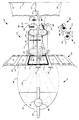
図1はオーバーアンダーレンズ(over-under lens)型3Dフィルムプロジェクションシステム100を示しており、このシステムはデュアルレンズ3Dフィルムプロジェクションシステム若しくはプロジェクタと称されることもある。矩形の左目用画像122と矩形の右目用画像123は共に3Dフィルム120上にあり、まとめて照射部107と称する光源及びコンデンサ光学系によって同時に照射される。照射部107はフィルムの後方に設けられ、左目用画像と右目用画像は開口プレート110によりフレーミングされており、フィルム120上の全ての他の画像が見えないようになっている。なぜなら、これら画像は開口プレートの不透明部分により隠されるか妨げられるからである。当業者であれば、明確さを確保するために、上記開口の内側エッジだけが図示されていることが理解できるであろう。左目用画像及び右目用画像は対となって立体画像ペアを形成し開口プレート110を介して見ることができる画像であり、オーバーアンダーレンズシステム130によってスクリーン150上に投影される。スクリーン上では、これら画像はほぼ位置合わせされて重なり合い、該2つの投影された画像の上部がスクリーン視聴エリアの上側エッジ152に一致し、該2つの投影された画像の下部がスクリーン視聴エリアの下側エッジ153に一致する。
FIG. 1 shows an
フィルムプロジェクタ100は正確な寸法で図示されていないが、本実施形態では照射部107を含み、該照射部はアーク灯101などの高輝度ランプを有し、該高輝度ランプはその中央に照射アークとしてエンベロープ102を有している。リフレクタ103は例示的な本実施形態において楕円106にほぼ沿った楕円形状として示されており、照射アークからの光線104を楕円106の第1焦点近傍に反射し、楕円106の第2焦点近傍にアークの画像105を形成する。ほとんどのフィルムプロジェクタにとって、照射アークの画像105はフィルムゲートに形成されるかフィルムゲート近傍に形成される。ここで、該フィルムゲートは開口プレートに形成された開口110として示されている。図1において開口110は、明確さを確保するために、開口プレートの開口の境界のみが図示された開口部として示されている。このように、照射アークからの照射は一様な面として提供されるので、開口110の開口全体に十分な照度が与えられる。
Although the film projector 100 is not illustrated with an accurate dimension, in the present embodiment, the film projector 100 includes an
立体フィルム120はフィルム基材121を有し、該フィルム基材の各エッジに沿ってパーフォレーション125の列が形成されている。パーフォレーションはスプロケット若しくはその他の機構と係合することができ、よって、フィルムを1つの画像が次の画像へとスムースに且つ連続的に進めることができる。上記したように、フィルム120上の画像は右側の画像と左側の画像の対として分けられている。図1に示された立体画像ペア(R1、L1)、(R2、L2)及び(R3、L3)はフィルム120に沿って設けられた隣接画像である。例えば、画像R2とL2を含む立体画像ペアは右目用画像122と左目用画像123に対応する。立体画像ペアを形成する2つの画像は同時に照射され、その際、2つの画像は開口110によって形成される開口部の内にある。同一の立体画像ペア内にある画像(例えば、画像122(R2)と123(L2))はフレーム内ギャップ124として定義される間隔だけ互いから隔てられている。連続する立体画像ペア、すなわち異なる立体画像ペアに属する2つの隣接する画像(例えば、左目用画像と右目用画像)、はフレーム内ギャップ128として定義される間隔だけ互いから隔てられている。フレーム内ギャップ128はフレーム内ギャップ124と同じ寸法であってもよいし異なる寸法であってもよい。プロジェクションシステム100の転倒性により、フィルム上の画像は転倒された状態でプロジェクタに供給され、スクリーンに投影される際に各画像は直立した向きで表示される。
The three-
レンズシステム130はレンズ体131を含み、該レンズ体は入口端133と出口端134を有する。入口端133はフィルム120に、出口端134はスクリーン150に面する。本実施形態において、レンズシステム130は、右目用画像を投影する上部と左目用画像を投影する下部とを有する立体デュアルレンズである。レンズシステム130の上部はフィルム側に入口レンズ要素136を、スクリーン側に出口レンズ要素138を有する。レンズシステムの下部はフィルム側に入口レンズ要素137を有し、スクリーン側に出口レンズ要素139を有する。レンズシステム130の上部と下部は隙間132によって隔てられている。隙間132は調整要素135によって調整可能であり、大きくしたり小さくしたりすることができる可変隙間幅を有することができる。本実施形態では、隙間132にはコーティング等が付設され、レンズシステムの上部と下部の間から光が漏れないようにしている。
The
また、レンズシステム130はフィルタモジュール若しくはフィルタアセンブリ140を含む。フィルタアセンブリ140は1つ若しくは複数の直線偏光子、円偏光子若しくはその他の非偏光フィルタ要素、例えば、アナグリフィック(anaglyphic)3D用の赤/青フィルタまたはマルチバンド干渉フィルタを有する。これらは全て、本技術分野では周知のものであり、右目用画像と左目用画像を分離するのに適しており、よって、聴衆160は立体的な上映を知覚することができる。
The
図1において右目用直線偏光子142は垂直方向に延びる偏光軸144を有するように描かれており、左目用直線偏光子143は水平方向に延びる偏光軸145を有するように描かれている。照射部107から発せされた光は、中心線126により代表されて示された光線の集合として、右目用画像122を通過し、レンズシステム130の上部によりスクリーン150上に映される。偏光子142を通った光線部分は中心線146によって示されており、スクリーン150に入射し、偏光軸144にほぼ平行に偏光される。同様に、照射部107から発せされた光は、中心線127により代表されて示された光線の集合として、左目用画像123を通過し、レンズシステム130の下部によりスクリーン150上に映される。偏光子143を通った光線部分は中心線147によって示されており、スクリーン150に入射し、偏光軸145にほぼ平行に偏光される。
In FIG. 1, the right-eye
適切にアライメントが取られていると、右目用画像122と左目用画像123の投影はスクリーン150上でほぼ重なる。2つの投影された画像のそれぞれの中心はスクリーンの中心151とほぼ一致する。これは図1において中心線146と147の収束により表わされている。投影されると、画像122及び123の上部はともに、ほぼスクリーン150の上部152に沿って映され、画像122及び123の下部はともに、ほぼスクリーン150の下部153に沿って映される。
When properly aligned, the projections of the right-
フィルタモジュール140が偏光コンポーネント、例えば、直線偏光子142及び143を採用するなら、スクリーン150は偏光保持特性を発揮するであろう。そのような偏光保持スクリーンの一例は銀幕である。一方、フィルタモジュール140が偏光コンポーネントを備えていないならば、スクリーン150は偏光保持特性を有する必要はない。
If the
聴衆160には3Dメガネが提供されており、該3Dメガネは右目用部分171と左目用部分181を有する。図1の例示的なレンズシステムには偏光要素が使用されているので、3Dメガネの右目用部分171は第1の方向に偏光軸173を有する直線偏光子172を含み、左目用部分181は第2の方向に偏光軸183を有する直線偏光子182を含む。第2の方向は偏光軸173の第1の方向に垂直である。立体画像を投影するために、例えば、時計回りの円偏光と反時計回りの円偏光の円偏光要素がレンズシステムにおいて採用される他の実施形態では、3Dメガネには上記2つの目の部分に円偏光子が設けられる。
図1の例示的な実施形態に示されているように、偏光軸173は偏光軸144にほぼ平行であり、投影された右目用画像はスクリーン150からの反射の後、右目用偏光子172を通過して聴衆160により視聴される。上記投影された右目用画像の同じ反射光は左目用偏光子182を通過しない。なぜなら、右目用画像の偏光軸144が左目用偏光子182の軸183にほぼ垂直だからである。よって、右目用画像122の投影のみが聴衆160の右目170に到達する。同様に、左目用画像123の投影のみが聴衆160の左目180に到達する。なぜなら、左目用画像の偏光軸145が右目用偏光子172の軸173にほぼ垂直であるからである。
As shown in the exemplary embodiment of FIG. 1, the
3Dメガネ未着用の視聴者は右目用画像122と左目用画像123の投影の重なりを見るだろうが、該重なった画像から3D効果を知覚することはできないだろう。これが、本発明の技術思想に基づいて説明された種々の調整を行うオペレータにとっての第1のモードとなる。
A viewer who is not wearing 3D glasses will see the overlap of the projection of the
図2は本発明の技術思想に基づいて構成されるテストパターン200を示している。テストパターン200はプロジェクションシステムの下記の状態の1つ若しくは複数を判断して補正する際に用いられるのに特に適している。
・レンズシステム130が適切な方向に向けられて、右目用画像122及び左目用画像123が投影された際に水平方向のアライメントが取れているか。
・レンズシステム130が正しく収束して、右目用画像122及び左目用画像123が投影された際に垂直方向のアライメントが取れているか。
・照射部107のバランスが取れており、同程度のレベルの照射が右目用画像122及び左目用画像123の投影に与えられているか。
FIG. 2 shows a test pattern 200 configured based on the technical idea of the present invention. The test pattern 200 is particularly suitable for use in determining and correcting one or more of the following states of the projection system.
Whether the horizontal alignment is obtained when the
Whether the
Is the
正しい方向に向けられているレンズシステムにおいては、レンズシステム130の上部は下部の直上、すなわち、垂直方向上方に位置し(つまり、レンズ要素138と139の中心点を結ぶラインがほぼ垂直になる)、投影された左目用画像と右目用画像は該2つの画像の間に側方向のオフセットを有さず水平方向に位置合わせされる。正しく収束されたレンズシステムにおいては、レンズ上部及びレンズ下部は垂直方向に分離し、その結果、左目用画像と右目用画像は互いに対して垂直方向のオフセットを有さずに投影される。
In a lens system oriented in the correct direction, the top of the
明示された表示220及び221(RIGHTという文字とLEFTという文字)は、それぞれ右目用画像122及び左目用画像123の正確な識別を補助する。表示220及び221は、3Dシステムの偏光子モジュール140及び聴衆160に提供された3Dメガネが互いに適合しており正しく設けられているかを判断する際に特に有用である。
テストパターン200は右目用画像122と左目用画像123を含み、これら画像はフィルム120に繰り返し記録されているものであり、該フィルムはループ状にされ、その結果、システム評価及び/またはアライメント動作を行う間にフィルムが3Dプロジェクションシステムの中を進むと、テストパターンの画像が連続的にスクリーン150に投影される。静止画像を使用する場合とは異なり、フィルムを進行させ続ける必要がある。これは照射部107からの放射エネルギにより、ゲートで静止しているフィルム120の静止セグメントにおいて孔が焼けることを防ぐためである。
The test pattern 200 includes a right-
テストパターン200において、右目用画像122は矩形エリア202により、左目用画像123は矩形エリア203により区画される。これら矩形エリアの大きさは、投影されるべきフィルムフォーマットに基づいて選択される。図示された例示的な実施形態において、矩形エリア202及び203はフィルム120上の0.810インチ幅の画像を表している。各矩形エリアは2.39:1のアスペクト比を有しており、これは「スコープ(scope)」画像である。矩形エリア202及び203は幅wを有する「安全エリア」を示し、プロジェクタが正しくアライメントされていると、矩形エリア202及び203は投影の際に劇場遮蔽物に隠されることはない。劇場遮蔽物は一般的に、黒いカーテンを含むと考えられ、スクリーンのエッジに掛けられ、図示されていない。3Dフィルム製作者は、画像が投影面若しくは遮蔽物のエッジに視覚的に接触すると3D効果が得られないシーンを頻繁に作る。
In the test pattern 200, the
また、テストパターン200には、左右の境界ライン205が示されており、このライン間距離はd1であり、これはフィルム上の0.825インチ幅の画像の最大水平寸法に対応する。距離d1は幾つかの一般的な2Dフィルムフォーマットにおける画像の予想幅を表して且つフィルムテストパターン200から投影されるべき画像の典型的な最大水平量を表す。通常のフィルム上映及びフィルム視聴の間に適用される特定の慣例に基づいて、矩形エリア202及び203によって示された安全エリアはスクリーン上に表示されなければならない画像エリアに対応し、一方、距離d1だけ離された境界ライン205の内側に含まれる領域はスクリーン上に表示され、境界ライン205の外側の境界外領域は表示されない。
The test pattern 200 also shows left and
テストパターン200の外側境界エッジ206はカメラの対応ゲート開口の水平範囲を表しており、該水平範囲は距離d2として示されている。例示的な実施形態において、距離d2は多くの場合0.866インチになるように設定される。図1では大まかに描かれているが、フィルムは外側境界エッジ206を超える領域を含む。この領域は補助的なフィルム情報、例えば、光学サウンドトラック、デジタルサウンドトラック、タイムコードトラック(図示せず)を含むと共にパーフォレーション125を含む。該補助的なフィルム情報はデジタル情報であってよい。
The
図1に示されているように、同一の立体ペアの連続する(または隣接する)右目用画像と左目用画像はフレーム内ギャップ124によって隔てられており、これは画像の連続する立体ペアの間のフレーム内ギャップ128とほぼ同じように見える。これら2つのギャップの見た目が同様なので、立体フィルムの編集をする人間にとっては紛らわしい場合がある。編集の際に立体フィルム120を1つのフレーム内ギャップ124の所でカットし、そのようなカットは処理上のミスであり、フレーム内ギャップ128でカットされた立体フィルムの別のストリップ(strip)につなぎ合わされると、交互に配置されて連続する左目用画像と右目用画像の順序が崩れてしまい、投影される映像が立体からシュードスコピック(pseudoscopic)に変わってしまう。シュードスコピック映像の場合、投影された右目用画像が左目によって見られ、投影された左目用画像が右目によって見られる。換言すると、画像は間違った目によって見られる。その結果、聴衆の目が疲れてしまい、不快感を与えてしまう。
As shown in FIG. 1, consecutive (or adjacent) right-eye and left-eye images of the same stereo pair are separated by an
米国特許庁に同時係属している米国特許出願第_______号(名称「投影フィルムのための指標マークを備えたシステム及び方法」、代理人整理番号PU090130、出願日:2010年9月16日)は本明細書に組み込まれるものとする。この米国特許出願では目盛マーク207が設けられて、フレーム内ギャップ128の近傍の領域を示している。この目盛マークの所で編集もしくはカットが行われる。警告バー208が設けられて、編集を行ってはいけない場所、すなわち、フレーム内ギャップ124の所またはその近傍、をはっきりと示している。目盛マーク207及び警告バー208はフレーム境界205の外側に位置している。このように、マーク207及び208はスクリーン150上に投影されたいかなる画像においても見られることがあってはならない。さらに、マーク207及び208は限界206の内側に設けられてフィルム120の左右のエッジから離れているので、これらマークは、外側境界エッジ206を超えてフィルム上に存在することもある補助的な情報、例えば、光学サウンドトラックその他(図示せず)を読み取る際に干渉しないと考えられる。
U.S. Patent Application _______________________ (named "System and Method with Index Marks for Projection Film", Attorney Docket Number PU090130, Filing Date: September 16, 2010) It is incorporated herein. In this US patent application, a scale mark 207 is provided to indicate a region in the vicinity of the in-
図2においてフレーム内ギャップ128の半分と目盛マーク207の半分がテストパターン200の上部エッジと下部エッジに示されており、テストパターン200がフィルム120に繰り返し記録されると、フレーム内ギャップ128の半分と目盛マーク207の半分が一体化して1つの完全な形のフレーム内ギャップ128と1つの完全な形の目盛マーク207が形成される。マスク207及び208は異なる形状、デザイン、パターン若しくは色を有してもよい。例えば、上記マークはブランクマーク若しくは明るいマークとして暗い背景に対して設けられることにより、視覚的な認識及び検査ができるようにする。図2に示された1つの例示的な実施形態において、マーク207は三角形または矢印として形成され、マーク208はバーまたは細長いストリップとして形成され、よって、これら2つのマークは互いに対して実質的に垂直になる。
In FIG. 2, half of the
複数の焦点目標物201、中央画像幅レチクル204及び背景グリッド209も、テストパターン200に設けられている。同様の要素が標準2Dテストパターン、例えば、米国映画テレビ技術者協会(Society of Motion Picture and Television Engineers)のSMPTE RP40及び35PAに見られる。
A plurality of focus targets 201, a central
焦点目標物201は右目用画像122及び左目用画像123の各々の中心近傍に位置していると共に、これら画像の上部エッジ、下部エッジ及び側部エッジの周りに位置している。これら焦点目標物が投影されると、該焦点目標物によって、スクリーンの全領域に亘って焦点を正確に判定することができる。図示されているように、焦点目標物201は、3画素幅、2画素幅及び1画素幅で描かれており、2048画素幅の出力のために設定されたデジタルフィルムレコーダを使用して出力することができるようになっている。他の実施形態においては、高解像度アートワークを写真技術により縮小することで生成されるテストパターン、または、大きな画素数用に設定されたフィルムレコーダにより生成されるテストパターンは、インチ毎にラインペアで較正されるか、別の同じような計量単位で較正される。
The
他の例示的な実施形態においては、中央焦点目標物294、294’、295、295’は図2に示された実施形態とは異なる配置で設けられる。中央焦点目標物294、294’、295、295’はそれぞれ異なるパターンを呈し、部分的に焦点目標物201とも異なる。特に、右目用画像122及び左目用画像123の各々において同一とするのではなく、他方の目用の焦点目標物294’及び295’を黒いフィールド(図示せず)によって置き換えることができる。このように同じ目の焦点目標物294と295のみが、それぞれ右目用画像及び左目用画像に投影された焦点目標物となる。この実施形態において、レンズシステム130の上半分と下半分が別々に焦点を合わることができる場合に以下のことが重要である。すなわち、3Dメガネを装着することの恩恵を受けない映写技師は独自に、中央の左目用焦点目標物295(左目用の指標221の近傍にあり、この指標は、左目用焦点目標物の記憶を助ける物(mnemonic)として機能し、目標物295が関連している目を特定することができる)の投影を観察することによって左目用画像123の焦点を評価することができると共に、中央の右目用焦点目標物294(右目用の指標220の近傍にあり、この指標は、目標物294が関連している目を特定する際の追加的な補助となる)の投影を観察することによって右目用画像122の焦点を評価することができる。同じように、右目用画像122または左目用画像123の一部を黒くするという技術はテストパターン200内の任意の場所で使用することができ、よって、他方の目用の画像の選ばれた指標、レチクル若しくは領域についてより鑑識眼のある表示ができるようになる。
In other exemplary embodiments, the central focus targets 294, 294 ', 295, 295' are provided in a different arrangement than the embodiment shown in FIG. The central focus targets 294, 294 ', 295, 295' each have a different pattern and are partially different from the
画像幅のレチクル204は右側の画像122と左側の画像123の両側に位置し、例えば、アライメントが未だ理想的になっていない場合に遮蔽物位置若しくは投影の大きさがどれくらい不正確かを判断するのに用いられる目盛を構成する。レチクル204はまた、開口プレートをカットしたりヤスリがけしたりしてプロジェクタ開口110のサイズを調節する際にも使用できる。遮蔽物が0.825インチの投影開口205のエッジと投影された矩形202若しくは203との間にあれば、アライメントは理想的であると考えられる。
The
背景グリッド209は右目用画像122と左目用画像123の各々において同一である。グリッド209を使用して焦点を評価し、投影された画像全体のアライメントを評価することもあるが、グリッドの主要な意義はレンズ130及び偏光子モジュール140を通過する放射エネルギを低減することである。このエネルギ低減は約50%低減であると推定される。テストパターン200はプロジェクションシステム100に長い時間表示することができるので、グリッド209または伝達される放射エネルギを低減するのに適した他の同様の要素は、プロジェクションシステム100の要素へのダメージを緩和する。これは、照射部107からの強い光に長い時間晒されるために発生する熱があるからである。
The
右目用画像122は垂直中心線210と水平中心線212を有する。同様に、左目用画像123は垂直中心線211と水平中心線213を有する。これら2つの画像が同時にスクリーンに投影されると、該中心線を使用して、レンズシステム130の向き及び収束が正しく設定されているかを、少なくともおおよその程度で、視覚的に示すことができる。しかし、設定の精度の向上及びレンズ130の向き及び収束の細かい目盛調整の確認が3D画像の上映においては望まれる。さらに、3D画像の上映においては、右目用画像と左目用画像の間の照射バランスの判定及び設定についても改善が望まれる。
The right-
向き、収束及び輝度バランスは全て、3D上映における視聴感覚に影響を及ぼす。向き、収束及び輝度バランスに関する改善についての要求は、2つの新しいパターンをテストパターン200に加えて使用することにより、全て満足される。該新しいパターンは、画像122及び123の中央部にそれぞれ設けられた「反対の」若しくは「対向する」チェックボードパターン214及び215を含む。これらパターン214及び215のパターンの細部は異なる向き若しくは方向で配置されている。図示された例示的な実施形態において、これら2つのパターンは、実際のチェックボードレイアウト及びシェーディングに関して、互いに共役関係若しくは相補関係にある。
Orientation, convergence and brightness balance all affect the viewing sensation in 3D screening. The requirements for improvements in orientation, convergence and brightness balance are all satisfied by using two new patterns in addition to the test pattern 200. The new pattern includes “opposite” or “opposing” checkboard patterns 214 and 215 provided in the center of
テストパターン200が適切な収束、方向及びバランスの取れたプロジェクタ100から投影されると、2つのチェックボードパターン214及び215がぴったりと重なり合い、右目用画像122からのチェックボードパターン214の薄色すなわち明るい四角形がスクリーン150上で左目用画像123からのチェックボードパターン215の暗い四角形に組み合わされるが、逆の組み合わせも有り得る。完璧にアライメントが取られているときは、2つの反対のチェックボードパターン214と215の組み合わせがスクリーン上に連続したグレーのフィールドを形成する。これについては図6に基づき詳述する。一方、輝度バランスについてアライメントが取れていない場合または輝度バランスの調節が間違っている場合、色々な明るいアーチファクト(artifacts)と暗いアーチファクトが生成され、よって、チェックボードパターンがスクリーン上に見えたままになる。このとき、チェックボードの四角形のエッジが見えたままになる。このことについては、図3−図5を参照して詳述する。このような結果は、背景グリッド209を用いた場合は生成されることがなく、対応する効果も得られない。なぜならグリッド209内のチェックボードパターンは右目用画像122と左目用画像123において同一であるからであり、従って、アライメントが取れているプロジェクタによって投影されると、該2つの画像はどちらか一方のグリッドに示される黒と白のチェックボードパターンと同じチェックボードパターンを生成するからである。
When the test pattern 200 is projected from a properly converged, oriented and balanced projector 100, the two checkboard patterns 214 and 215 overlap exactly, and the checkboard pattern 214 from the
3Dで最適な上映をするためにプロジェクタ100及びレンズ130を調節する例示的な較正方法700が図7のフローチャートに示されている。この方法の各ステップは、テストパターン200の投影を参照しながら下記において使用可能な順序で説明される。該テストパターンの投影は3Dメガネを装着せずにプロジェクタ100を調節する技師(図示せず)によってスクリーン150上において観察される。目に見える可能性のある複数のスクリーンパターンはテストパターンの投影の結果見えるものであり、いくらかのプロジェクタ調節及び/またはレンズ調節が必要であることを示すが、該スクリーンパターンが図3A、3B、4A、4B、5A、5C及び6に示されている。このことについては較正方法700を説明する際に触れる。プロジェクタ100またはレンズ130に対して較正方法700の実行により成されるべき調節は、図3C、4C及び5Bに示されている。
An
以下の説明のために、図3Cのプロジェクションシステム300は幾つかの不正確な調節若しくはアライメントを含み、従って、較正が必要な状態にあるように図示されている。このような不正確な調節やアライメントがあると、それに対応するエラーが生ずることになり、該エラーは本発明の1つ若しくは複数の特徴部によって検出されて補正される。第1に、アーク灯301の中心がリフレクタ103に対してずれている。この場合、中心近傍にアークを持ったエンベロープ302が形成され、該エンベロープはアークから画像305を形成する光線304を生成する。この画像は最終的に開口110の中心に表示されない。この状況では、図3A、3B、4A、4B及び5Aに示されているように、画像305は右目用画像122の近くに形成されるので、右目用画像の投影が左目用画像の投影より明るくなる。また、右目用チェックボードパターン214(Rが書かれている四角形)が左目用チェックボードパターン215(Lが書かれている四角形)より明るくなる。立体ペアの右目用画像の投影と左目用画像の投影との間に不均一な輝度があるという状態は、輝度アンバランスと称される。輝度アンバランスはチェックボードパターン214及び215に対応する、チェックボードパターンに付随する明るいアーチファクト及び暗いアーチファクトの存在によってスクリーン上で検出することができる。
For the purposes of the following description, the
第2に、レンズシステム130の上部と下部を分離するギャップ332が不正確な場合、右目用画像122及び左目用画像123の投影ビーム経路の中心線326及び327は偏光子142及び143を通過し、右目用画像及び左目用画像の、それぞれ中心線346及び347により表されている光線は、スクリーン150の中心151で収束しない。スクリーンの中心にビーム経路を収束させることができなかった状態は、本明細書において「誤収束(mis-convergence)」または「非収束(non-convergence)」と称す。全体的な誤収束はスクリーン上で、水平中心線212の投影と213の投影との分離として、はっきり目に見える。たとえわずかな誤収束であっても、チェックボードパターン214及び215における水平方向境界部に対応する、水平方向境界部に付随する明るいアーチファクト及び暗いアーチファクトの存在により、該わずかな誤収束をスクリーン上において検出することができる。
Second, if the
第3に、レンズ130がレンズマウント(図示せず)において回転中心軸330の回りに角度331だけ回転すると(回転中心軸は水平方向に延びている)、投影された右目用画像と左目用画像は水平方向に互いから離され、その結果、向きのエラーが生ずる。これは、本明細書では方向ミスとされる。全体的な不正確な向きはスクリーン上で、投影された垂直中心線210及び211の分離として、目で見ることができる。たとえわずかな不正確な向きであっても、チェックボードパターン214及び215における垂直方向境界部に対応する、垂直方向境界部に付随する明るいアーチファクト及び暗いアーチファクトの存在により、該わずかな不正確な向きをスクリーン上において検出することができる。
Third, when the
3つの全ての較正エラーまたはミスアライメントは較正方法700の使用により補正することができる。これらエラー状態の各々の補正の進捗は図4C及び5Bに示されたプロジェクションシステムに図示されている。完璧にアライメントが取られているシステム100は図1に示されている。
All three calibration errors or misalignments can be corrected by use of the
図7を参照すると、スタートステップ701のときにテストパターン200の右目用画像122及び左目用画像123を含むフィルムのリール若しくはループがプロジェクタ100に装着され、該プロジェクタが始動される。アーク灯101が点灯し、遮光板(図示しないが、周知である)が開かれる。プロジェクタの適切な較正を達成するために、通常動作温度に達するまでプロジェクタを動かし続けることが好ましい。
Referring to FIG. 7, at the
投影ステップ702において、カーテンがあるなら該カーテンが開けられ、スクリーン遮蔽物(図示せず)が所望のアスペクト比に設定される。このステップにより、テストパターン200の右目用画像122及び左目用画像123がスクリーン150に投影され、よって、オペレータまたは自動システムが画像をスクリーン上に焦点合わせする。上部スクリーン遮蔽物及び下部スクリーン遮蔽物はスクリーンの見える部分の上部エッジ152及び下部エッジ153にそれぞれ設定されており、スクリーン上における投影の中心合わせをするためのフレーミング目標物としても使用される。最初の焦点合わせは大まかなまたは予備的な調節でしかないこともある。なぜならシステムのアライメントはかなりずれている可能性があるからである。アライメントエラーが補正されるのに伴い、焦点合わせ(focusing)をさらに行う必要が生ずることもある。
In
最初の焦点合わせは様々な手法により行なえる。例えば、投影されたテストパターンの中の幾つかの文字またはその他の特徴(feature)に対して視覚焦点合わせをする。焦点合わせ機構の詳細は、該レンズアセンブリの構成により変わり得る。一般的に、焦点合わせは、軸330に沿ってレンズシステム130をフィルム120に対し近づけたり遠ざけたりすることで行われる(図3C参照)。幾つかの場合、図示のオーバーアンダーレンズアセンブリにあっては、レンズシステム130の上部はレンズの下部に対して独立に調節ができる。
The initial focusing can be done by various methods. For example, visual focusing is performed on some characters or other features in the projected test pattern. Details of the focusing mechanism may vary depending on the configuration of the lens assembly. In general, focusing is performed by moving the
垂直中心線評価ステップ703において、投影された左目用画像及び右目用画像は立体ペアのための十字線(crosshiars)の垂直中心線間のミスアライメントの存否について検査される。例えば、図3Aに示されているように右目用垂直中心線210の投影310と左目用垂直中心線211の投影311との間の水平方向変位は、ミスアライメントがあることを示す。水平中心線の投影312及び313はこのステップにおいて一時的に無視される。このステップで行われる調節は、画像の水平方向の変位を少なくとも大まかに補正する。より精密な調節は、該方法の後段においてチェックボードパターンを使用して達成される。投影された中心線310及び311がさらに整列位置に近づきほぼ重なる位置になるまで、対向する右目用チェックボード214と左目用チェックボード215からの投影314及び315のアライメントはこの段階では一時的に無視される。
In a vertical
投影された垂直中心線310と311が図3Aに示されているように左若しくは右に水平方向オフセットの分だけミスアライメントされている場合は、投影された中心線310はスクリーン150上で投影された中心線311の左側に見え、補正処理が向き調節ステップ704において取られる。図3Cを参照すると、レンズの向きは矢印333の方向において中心軸330の回りにレンズシステム130を回転することにより調節される。このタイプのレンズの回転は角度331をゼロに向けて減少させる。角度331は図3Cにおいて2つの破線により規定される。該2つの破線の一方は、レンズの上部及び下部の中心を通る横方向軸に対応し(例えば、レンズアセンブリの出口端における断面図を参照)、他方の破線は垂直基線に対応する。このように角度331は垂直方向からどれくらいレンズの横方向軸がずれているかを表す。
If the projected
投影された中心線310と311の間のオフセットが反転されて見え(図示せず)、よって、投影された中心線310がスクリーン150上で投影された中心線311の右側に現れる場合、向き調節ステップ704における適切な補正処理はレンズ130を矢印333の反対方向に回転させるという補正処理になる。換言すると、レンズシステム130の向きは、レンズを中心軸330の回りに回転させることにより2つの方向のうちの一方において調節されて、少なくとも大まかな水平方向アライメントを達成する。これは図3Aのミスアライメントとは対照的に、図3Bに示されているように、立体画像の投影された垂直中心線310’と311’の重なりを改善することによってなされる。
Orientation adjustment if the offset between the projected
向き調節ステップ704に関して上述した補正のための調節の結果、右目用垂直中心線210と左目用垂直中心線211の投影は少なくとも部分的にオーバーラップする。これは図3Bにおいて、投影された中心線310’と311’として示されている。投影された垂直中心線310’及び311’に対しておおまかなアライメントが達成されると、右目用画像122、左目用画像123、及び背景グリッド209における垂直中心線210、び211、及び焦点目標物201などのテストパターンの共通の画像要素は、適切に投影されるならば互いに重なる。これら共通の画像要素は、この時点で画像のより精確なアライメントを達成するためには、価値のないものになってしまうので、較正方法700は水平中心線評価を行うことによってステップ705に進む。
As a result of the adjustments for correction described above with respect to the
水平中心線評価ステップ705において、投影された左目用画像及び右目用画像は立体画像ペアに関するテストパターンの十字線の水平中心線間のミスアライメントの存否について検査される。例えば、図4Aは右目用水平中心線212の投影412と左目用水平中心線213の投影413との間の垂直方向変位を図示しており、これは水平中心線のミスアライメントを示している。水平中心線の投影412と413の間の距離若しくは間隔411は、図3Cの収束していない投影中心線346及び347がスクリーン150上で隔てられている量に対応する。水平中心線の投影412及び413がさらに整列位置に近づきほぼ重なる位置になるまで、対向する右目用チェックボード214と左目用チェックボード215の投影414及び415のアライメントはこの段階では一時的に無視される。
In the horizontal
水平中心線の投影412及び413が図4Aに示されているようにミスアライメントされ、投影された中心線412がスクリーン150上で投影された中心線413の上に見える場合、収束調節ステップ706による適切な補正処理が、較正ネジ若しくはその他の適切な代替物等の調節機構135(図4C参照)を回転することによって取られる。該調節機構の回転により、レンズシステム130の上部と下部を分離しているギャップ332が小さくなる。ギャップ332が小さくなると、水平中心線の投影412と413が近づきほぼ重なる。よって、投影された左目用画像と右目用画像の間の垂直方向ミスアライメントもしくは不一致が小さくなる。この補正結果は、調節機構135を図4Cの矢印433によって示された方向に回転することにより得られる。
If the
各レンズアセンブリは図示された構成とは異なる構成を有してもよい。例えば、ギャップ及び調節機構について異なる構成を有してもよい。レンズアセンブリの1つの実施形態においては、ギャップはレンズの長手方向に沿って一定である。他の実施形態においては、ギャップは可変のギャップであってもよい。可変ギャップの場合、スクリーンに近い端部のギャップが、フィルムに近い端部のギャップより大きい。他の実施形態においては、ギャップはレンズの一端で変化し他端で固定される。各レンズアセンブリの特定の詳細構成にかかわらず、ギャップ調節による収束補正は一般に、本明細書に記載されたように行われる。 Each lens assembly may have a configuration different from the illustrated configuration. For example, the gap and adjustment mechanism may have different configurations. In one embodiment of the lens assembly, the gap is constant along the length of the lens. In other embodiments, the gap may be a variable gap. In the case of a variable gap, the end gap close to the screen is larger than the end gap close to the film. In other embodiments, the gap varies at one end of the lens and is fixed at the other end. Regardless of the specific details of each lens assembly, convergence correction by gap adjustment is generally performed as described herein.
投影された中心線412と413の間のオフセットが図4Aに示されたものと比較して反転して見え(図示せず)、右目用の投影された中心線412がスクリーン150上で左目用の投影された中心線413の下に見える場合、収束調節ステップ706の補正処理では、調節機構135を矢印433(図4C参照)の反対方向に回転させてレンズ130の上部と下部の間のギャップ332を増大させる。ギャップ332を調節することによって、垂直方向における投影右目用画像と投影左目用画像の適切な収束が達成される。これは図4Bにおいて、水平中心線のアライメントによって示されている。換言すると、レンズシステム130の収束はレンズの上部と下部の間のギャップ調節によって2つの方向のうちの一方において調節され、その結果、少なくとも大まかな垂直方向アライメントを達成することができる。これは、図4Aのミスアライメントとは対照的に、図4Bに示されているように、立体画像の水平中心線の重なりが改善されたことによる。
The offset between the projected
レンズシステム130の実際の構成に応じてギャップ332のサイズを変化させることにより、開口110に対するレンズ130の中心線330の位置を変えることができる。例えば、Condon構成のレンズにおいては、レンズの半分の取り付けは強固であるが、別の半分は1つのエッジに沿って回転することができ、よって、ギャップレンズが開閉されると、中心線が上下に移動し且つ左右にも少し動く。他の実施形態においては、レンズ取り付け部はレンズ上半分と下半分の回転を共に可能にするか、平行移動を可能にし、互いに近づいたり離れたりすることができる。このような実施形態では、ギャップが変化しても中心線の変化は無い。開口110内のフレーム120のフレーミングを変えることにより上記のような動きを補正すると、焦点がシフトする。「フレーミング(Framing)」はプロジェクタに関する設定であり、シャッタが開かれている間にフィルムを止める際に目標物を効率的に動かすことを言う。シャッタが閉じられるとき、フィルムが進む。その結果、フィルムのフレームの中央部がレンズの中央に対して上下にシフトする。もしレンズを開いて収束を改善すると、画像の中心も、レンズの実際の構成に応じて、上方または下方にシフトする。この動きはフレーミングを調節すること及び画像を画像シフト方向とは正反対の方向に上方移動若しくは下方移動することにより補正可能である。
By changing the size of the
レンズシステム130の幾つかの実施形態については、もしアクセスが可能な構成になっているなら、投影中には容易にアクセスできない位置に調節機構135が設置される。このような場合、立体画像の収束に対する補正をするためには、方法700を修正しなければならない。焦点合わせ、垂直中心線アライメントの評価及び垂直中心線調節のためのステップ702、703及び704は、収束調節の後に繰り返し行われなければならない。
For some embodiments of the
収束調節ステップ706においてなされる補正のための調節を行うと、右目用水平中心線212の投影と左目用水平中心線213の投影は、少なくとも部分的に重なり合う。これは図4Bにおいて投影された水平中心線412’及び413’により示されており、よって、少なくともおおまかな収束、すなわちおおまかな垂直アライメントが右目用画像の水平中心線と左目用画像の水平中心線との間で達成される。向き調節ステップにおいて上述したように、適切に投影されるとほぼ重なり合う右目用画像122及び左目用画像123における水平中心線212、213、焦点目標物201及び背景グリッド209などの共通の画像要素は、この時点でより正確なアライメントを達成するという観点においては小さな意味若しくは限定的な意味しか持たない。従って、較正方法700はステップ707に進む。
When adjustment for correction performed in the convergence adjustment step 706 is performed, the projection of the
輝度バランス評価ステップ707では、投影された左目用画像及び右目用画像は輝度アンバランスを有するか否かについて検査される。図示5Aは右目用及び左目用の対向するチェックボードパターン214及び215の投影514と515との間の輝度差の一例を示している。この場合、右目用画像若しくはパターン514は左目用画像515より明るい。輝度におけるこのようなアンバランスは、照射源の位置を、すなわち、より詳しくはアーク灯301の位置を調節することにより補正可能である。幾つかのプロジェクタについては、リフレクタ103への調節または他の集光系(図示せず)への調節またはアーク位置決め用磁石などの他の機構への調節が、アーク灯301への調節に加えてもしくは代えて必要となる。
In the luminance
図5Aに示された特定の例においては、右目用に投影されたチェックボード514は投影されたチェックボード515より明るく見える。この場合の補正処理は、図5Bに示されているように矢印501の方向にエンベロープ302(または照射源)の位置を上昇することによって、輝度調節ステップ708で行われる。この調節により、実際に開口110におけるアークの画像305が下降する。なお、右目用画像は、アークの画像305が開口の中心位置より上にある場合にはより明るく見える。なぜなら、照射面の中心近傍のフラックス(flux)はエッジより大きいからである。この調節は、投影されたチェックボード514及び515がほぼ等しいレベルの輝度を有するまで、繰り返し行われる。
In the particular example shown in FIG. 5A, the
チェックボードの投影514と515の相対的な輝度が図5Aの場合の反対であって右目用チェックボードの投影514’が左目用チェックボードの投影515’より暗い(図5C参照)ならば、アークの画像は開口110において低すぎてしまう。このタイプのアンバランスの補正は、図5Bの矢印501により示されている方向とは逆方向にエンベロープ302若しくは照射部を降下することにより達成される。
If the relative brightness of the
輝度バランス評価ステップ707において、テストパターン内の十字線の重ねされて投影された垂直中心線510と水平中心線511(図5A参照)のアライメントは一時的に無視される。対向するチェックボードの投影514と515の間のわずかなミスアライメントは、2つのチェックボード投影514と515の内の明るい方だけでなくそれを越えて輝度における不連続性を生成する。この問題への対処については下記において詳述する。
In the luminance
ステップ702−708における上記のようなレンズの向き、収束及び輝度バランスに対する第1ステージの大まかな調節が終了すると、方法700において第2ステージの調節が行われ、より細かなアライメント及びより精密な補正を達成する。第2のステージの調節はステップ702’からスタートする。ここで細かな調節がフレーミングに対して行われることで、画像は開口100内で適切にセンタリングされ且つスクリーン上でも適切にセンタリングされることが保証される。このとき焦点合わせも実施される。大まかなアライメントは終了しているので、焦点合わせ目標物201(図2参照)の使用は焦点をより正確にするために有意義である。なぜなら、該焦点合わせ目標物は、アライメント処理の初期段階よりも正確にアライメントされているからである。焦点合わせ目標物201を使用し続けることは有意義であり続け、その後の焦点チェック若しくは最終焦点チェックにおいて有益である。
When the first stage rough adjustments to lens orientation, convergence, and brightness balance as described above in steps 702-708 are completed, the second stage adjustments are made in
向き評価ステップ703’において、垂直中心線の投影310’と311’(図3B参照)は、ステップ704で達成されたおおまかなアライメントの結果として、ほぼ重なって見える。しかし、テストパターン画像からのチェックボード投影314’と315’の間の垂直境界部(またはオーバーラップ領域)は高い輝度の領域316と低い輝度の領域317を表示し続ける。この表示は2つの垂直中心線の投影がほぼ完全に重なり合うまで続く。従って、垂直方向の境界領域における高い輝度の領域316と低い輝度の領域317を、レンズの向きに対してかなり詳細なレベルの補正を達成するための副尺として使用することができる。このように、レンズアセンブリ130の向きを調節して角度331(図3C参照)をゼロに低減することができ、よって、収束エラーを実質的に除去することができる。
In the
対向する右目用チェックボード214及び左目用チェックボード215の投影314’と315’が図3Bに示されているようにミスアライメントされている場合(向きが少し不正確で、収束が大きく不正確)、次の2つのアーチファクトを3Dメガネを通して投影画像を見ないで観測できる。第1に、「L」が付けられた四角形(左目用チェックボードの投影315’の四角形)の右に位置する「R」が付けられた四角形(右目用チェックボードの投影314’の四角形)については、右目用チェックボードの投影314’が左目用チェックボードの投影315’に対して左へオフセットされると(向きが少し不正確であるため)、明るい領域316がこれら2つの水平方向に隣り合うR四角形とL四角形の垂直方向境界部に現れる。この場合、相対的に狭い明るい領域316がR四角形とL四角形との間のオーバーラップ領域に対応する。第2に、「L」が付けられた四角形の左に位置する「R」が付けられた四角形との間の垂直方向の境界部において、右目用チェックボードの投影314’の同じ左側オフセットによって、R四角形がL四角形から左方向へ遠ざけられ、その結果、暗い領域317に代わってしまう。図3Bに示された特定のミスアライメントが観測されると(つまり右目用チェックボード314’の投影画像が左目用チェックボード315’に対して左方向へわずかな水平方向オフセットを有すると)、向き微調節ステップ704’において補正処理が行われる。この補正処理は、角度331をゼロに減ずるべく、図3Cに示されている矢印333の方向にレンズ130をその中心軸330回りに回転させることによりなされる。この調節は、第1の向き調節ステップ704における調節に比べ、微量であり且つ向きのエラーをより正確に補正する。該微調節は視覚ゲージとしてチェックボードを主に使用し、補助的にシステム内のどこかのアライメント向上部分を使用することで達成される。上記した後者のアライメントは現在のアライメントに対して垂直か独立しているが、幾らか補正されるまでは、人間の観察力に対して有害な効果を有すると思われる。本方法の他の実施形態では、チェックボードは、十字線調節の補充としてまたは十字線調節の代わりとして、ステップ704’まで待つのではなくステップ703/704との関連で使用される。
When the
同じような状況で上記したように、明るい領域316と暗い領域317の位置が反転すると(図示せず)、方向微調節ステップ704’における補正処理によって、レンズ130が矢印333とは反対方向に回転させられる。
As described above in the same situation, when the positions of the
向き微調節ステップ704’においてなされる補正による調節によって、十字線の垂直中心線210及び211の投影410及び510がほぼ重なり合うと思われ(それぞれ、図4A及び5A参照)、投影された対向する右目用チェックボードと左目用チェックボード(図4Aの領域414及び415を参照)の間の垂直方向の境界領域に沿った垂直方向の明るい領域316及び暗い領域317はほぼ無くなると思われる。この向きが達成され且つ投影された左目用画像及び右目用画像が互いに水平方向において正確にアライメントされていれば、較正方法700はステップ705’に進む。このステップでは、投影された右目用画像及び左目用画像におけるチェックボードパターンの水平方向境界領域を検査することによって、収束エラーのさらなる評価が行われる。
Due to the adjustments made by the corrections made in the
図4Bに戻ると、おおまかな収束はすでにステップ706において確立されているので、右目用水平中心線212及び左目用水平中心線213の投影412’と413’は、ほぼオーバーラップして見える。このとき、距離411’は例えば、スクリーン150において1インチ以下と比較的小さく、デジタル形式で書かれたフィルムにおいてはほんの1〜4画素に対応する大きさである。しかしながら、収束エラーがある限り、対向するチェックボード投影414’と415’の間の水平方向境界領域には輝度が増大した領域416及び輝度が低下した領域417が存在する。このような水平方向境界領域は収束エラー評価ステップ705’において、後述するようなより正確な収束エラー調節及びより細かい解像度を提供する副尺較正ツールとして利用することができる。
Returning to FIG. 4B, since rough convergence has already been established in step 706, the projections 412 'and 413' of the
対向する右目用チェックボード214及び左目用チェックボード215の投影414’と415’が図4Bに示されているようにミスアライメントされている場合、次のような2つのアーチファクトが、画像を見るための3Dメガネを用いることなく観察できる。第1に、「L」が付けられた四角形(左目用チェックボード投影415’の四角形)の下に位置する「R」が付けられた四角形(右目用チェックボード投影414’の四角形)については、右目用チェックボード投影414’が左目用チェックボード投影415’に対して上方にオフセットされているならば、明るい領域416が2つの垂直方向に隣接するR四角形とL四角形の水平方向の境界部において現れる。この場合、明るい領域416はR四角形とL四角形の間の狭いオーバーラップ領域に対応する。第2に、「L」が付けられた四角形の上に位置している「R」が付けられた四角形との間の水平方向境界部において、右目用チェックボード投影414’が同じように上方にオフセットされていると、暗い領域417が現れる(なぜならR四角形が隣のL四角形から離れる方向に移動するからである)。
If the
図4Bに示されているミスアライメントが観察される場合(つまり、右目用チェックボードの投影された画像414’が左目用チェックボード415’に対してわずかに垂直方向にオフセットされて上方に変位している場合)、収束微調節ステップ706’において補正処理がなされる。この補正処理では、ギャップ332のサイズを小さくして投影画像中心線446及び447をスクリーン上で互いに近けるべく、図4Cに示した矢印433の方向に収束調節機構135を回転させる。この調節により、第1の収束調節ステップ706で行われた調節よりも細かい調節が可能となり、より正確な収束補正を達成することができる。この場合、上記のような微調節ができる要因は、テストパターン内の対向するチェックボードにより生成される水平方向境界領域により提供された視覚ゲージが改善されていること、及び、焦点合わせが改善されていることであると考えられる。焦点及び収束は向きより強固な関係を有する。なぜなら焦点が変わると収束が変わるからである。
When the misalignment shown in FIG. 4B is observed (that is, the projected
水平方向境界部における明るい領域416と暗い領域417の位置が図4Bに示されている位置から逆にされると(図示せず)、向き微調節ステップ706’における補正処理では、収束調節機構135を矢印433とは反対の方向に回転させギャップ332のサイズを大きくする。
When the positions of the
上記したように、レンズシステム130の特定の構成によっては、ギャップ332に対する調節を行うと、望ましくない結果が生じたり(例えば、焦点ずれ)、調節機構に容易にアクセスできなくなってしまったりすることもある。このような情況では、収束調節を行う際には、修正された方法を使用する。すなわち、細かい焦点合わせ及び垂直方向アライメント評価、並びにこれらのおおまかな調節及び微調節が必要となり、ステップ702’、703、704、703’、704’は収束の微調節の後に繰り返されなければならない。
As noted above, depending on the particular configuration of the
収束微調節ステップ706’においてなされる補正による調節を行うと、テストパターンの十字線の水平中心線212及び213の投影がほぼ重なり合う投影511となる(図5A)と予想され、さらに、投影された対向する右目用チェックボードと左目用チェックボード(図5Aの領域514及び515参照)の間の水平方向境界領域に沿った水平方向の明るい領域416及び暗い領域417もほとんど無くなると予想される。投影された左目用画像及び右目用画像が互いに垂直方向にアライメントが取られると、収束補正が終了し較正方法700はステップ707’に進む。
When the adjustment by the correction performed in the convergence fine adjustment step 706 ′ is performed, the projections of the
輝度バランス詳細評価ステップ707’において、投影された左目用画像及び右目用画像は、ステップ708で実施されたおおまかな調節の後に残っている輝度アンバランス若しくは輝度レベル差の存否について検査される。例えば、右目用チェックボードパターン214及び左目用チェックボードパターン215の投影514と515は、図5Aまたは図5Cに示されているように異なる輝度を有する。輝度アンバランスは少なくとも部分的にステップ708において補正されているので、ステップ707’で検出される輝度差は、例えば、図5Aに示されたプロセスにおいて見えた前のレベルよりも小さいはずである。輝度アンバランスがまだあるなら、ステップ707及び708で説明した手法に基づいて補正による調節が行われる。しかし、もしチェックボードパターン214及び215の投影がチェックボードパターンの残余の明るい領域及び暗い領域のみを示すなら、このような追加的な補正調節はステップ707’においてのみ必要となる。図6における合成投影面612で示されているように、もしチェックボードの四角形を含む投影されたフィールドの輝度がほぼ均一若しくは等しい明るさ(暗さ)レベルであって、個々のチェックボードの四角形が互いに見分けられない(つまりチェックボードの四角形同士の間に境界が見えなか、認識することができず、チェックボードパターンの姿が最小限になる)ならば、輝度バランスをさらに補正するための追加のアライメント若しくは追加の調節は不要である。
In the luminance balance
代替実施形態においては追加の焦点チェックが、この時点で、焦点目標物投影631を使用して行われる。この際、スクリーン150の中央に向かう焦点目標物を重要視する。
In an alternative embodiment, an additional focus check is made at this point using the focus target projection 631. At this time, the focus target toward the center of the
ステップ707’または708’の最後に、プロジェクションシステム100はテストフィルム120及びテストパターン200mを使用して適切に焦点合わせされてアライメントが取られる。よって、適切な向き、収束及び輝度バランスを得ることができる。上映用意ステップ709は、テストフィルムをプロジェクタ100から取り外すステップと、本当の上映フィルムを装着するステップを含む。レンズ130のためのアライメント及び収束調節は、商業用フィルタプロジェクタにおいてフィルムを交換しても、機械的に固定されるか別の手段により変更不可能にされるので、更なる調節はレンズシステム130に対して必要ない。とはいうものの、上映フィルムの先端部(図示せず)が進行して上映できる位置にきたとき、最終的な焦点チェック(オプションである)をしてもよい。ステップ710において、上映フィルムはプロジェクションシステム100によって投影される。フィルムが終わると、上映フィルムは再装着され、次の上映のために焦点チェックが行われる。ステップ710の処理は特に制限なく繰り返してもよいし、必要なときに繰り返してもよい。方法700はステップ711で終了する。
At the end of step 707 'or 708', the projection system 100 is properly focused and aligned using the
図8は較正補正800の別の実施形態を示している。この実施形態は、3Dフィルム投影に用いられるレンズアセンブリ130等の立体レンズアセンブリにおける光学アライメントを取るために使用することができる。ステップ802で、図2に示されたような立体ペアのためのテスト画像がスクリーン上に投影され、フレーミング及び焦点調節が行われて、投影された画像がスクリーン上に焦点を合わせされて表示される。これは種々の方法で実行することができる。例えば、上述したように、幾つかの文字または特徴(features)に可視焦点を合わせることによって実行する。これは図7のステップ702と同様である。
FIG. 8 shows another embodiment of a
ステップ803において、投影された画像はレンズの向きについてミスアライメントが無いか、ステップ703について上述したのと同様に検査される。ステップ804において、レンズアセンブリの向きの調節が適宜行われ、例えばテストパターン200の垂直中心線210及び211を視覚的ゲージとして使用することによって、ステップ704で上述したのと同様に、第1の方向アライメント条件に基づいておおまかなアライメントが達成される。
In
ステップ805において、投影された立体画像は、立体ペアの投影された左目用画像及び右目用画像における垂直方向の不一致若しくはオフセットにより生ずる非収束の存否について検査される。これはステップ705に関して上述したものと同じである。ステップ806において、必要に応じて、レンズアセンブリの上部と下部との間の分離若しくはギャップに対する調節が行われるので、おおまかな収束は第1の収束基準に基づいて達成される。これは例えば、ステップ706に関して上記した説明と同じように、テストパターン200の水平中心線212及び213を視覚ゲージとして使用することにより行われる。
In
ステップ807では、投影された立体画像は輝度アンバランスの存否について、ステップ707において説明したものと同様に検査される。ステップ808では、必要に応じて、例えば、照射源及び/若しくはリフレクタ並びにフィルムゲート若しくは開口などの照射光学系の相対的な位置に対する調節が行われる。この調節は、輝度アンバランスを許容レベルに低減するために行われるものであり、ステップ708で説明したのと同様、対向するチェックボードパターン214及び215等を視覚ゲージとして用いて行われる。
In
ステップ802−808は、おおまかなアライメント、特に、レンズの向き、収束及び輝度バランスに関するアライメントをシステムに対して行うという、第1段階のアライメントであると考えることができる。
第2段階のアライメントは、図7のステップ702’−708’と同様のステップであるステップ812−818を含み、プロジェクションシステムに関するより精確なアライメント及びより正確な補正を達成するために使用される。ステップ812は、フィルムゲート若しくは開口におけるフィルムのフレーミングに関する更なる調節及び/または更なる焦点調節を含む。 The second stage alignment includes steps 812-818, which are similar to steps 702'-708 'of FIG. 7, and are used to achieve more accurate alignment and more accurate correction for the projection system. Step 812 includes further adjustments and / or further focus adjustments for film framing at the film gate or aperture.
ステップ813では、投影された画像がレンズの向きに関して残余のミスアライメントを含むかについて検査され、ステップ814では、必要であれば、視覚ゲージとして用いられるチェックボードパターンの垂直方向の境界領域に基づく第2の向きアライメント基準に基づいた調節が行われて、より正確なアライメントを達成する。これはステップ714において説明したのと同様である。例えば、レンズ回転の向きが正確でないことによって向きエラーが生じている場合、投影された左目用画像と右目用画像との間に水平方向のオフセットが生ずる。このオフセットは、投影されたチェックボードパターンの垂直方向の境界領域を検査して、隣接する明るいラインまたは領域若しくは暗いラインまたは領域が存在するか、すなわち現れているかどうかを調べることによって検出することができる。
In
ステップ815において、投影された画像は残余の非収束について検査される。この残余の非収束は、投影された立体画像の間の垂直方向のミスアライメントとして現れる。必要であれば、視覚ゲージとして用いられるチェックボードパターンの水平方向の境界領域に基づく第2の収束アライメント基準に基づいた調節がステップ816で行われて、より正確な収束を達成する。これはステップ706’において説明したのと同様である。例えば、デュアルレンズシステムの上部と下部の間の間隔が正確でないことによって収束エラーが生じている場合、投影された左目用画像と右目用画像との間に垂直方向のオフセットが生ずる。このオフセットは、投影されたチェックボードパターンの水平方向の境界領域を検査して、隣接する明るいラインまたは領域若しくは暗いラインまたは領域が存在するか、すなわち現れているかどうかを調べることによって検出することができる。
In
ステップ817では、投影された画像に輝度アンバランスが残っているかを検査する。この輝度アンバランスは、ステップ808の調節ステップ後に残っている残余のアンバランスから生ずるか、ステップ808において過度に補正がなされた結果として生ずる。ステップ818では、照射光学系(例えば、光源及び/またはリフレクタ等)とフィルムゲート若しくは開口の相対的な位置が調節され、投影された左目用画像と右目用画像との間の輝度アンバランスを許容レベルに低減する。この調節を行う際には、ステップ708または708’で説明したのと同様に、対向するチェックボードパターン214及び215等の視覚ゲージを使用する。例えば、フィルムゲートに対して照射部がミスアライメントされていることにより輝度アンバランスが生じている場合、投影された左目用画像と右目用画像との間に輝度の差が生じてしまう。この差は、投影されたチェックボードパターンにおける四角形の相対輝度を検査することによって検出することができる。輝度アンバランスがある場合、投影された画像は所定のパターンで隣接する明るい領域と暗い領域を含む(または、相対的に輝度が異なる領域を含む。つまり、比較したときにより明るい領域とより暗い領域を含む)。上記所定のパターンとは、右目用チェックボードパターン及び/または左目用チェックボードパターンにおける相対的な輝度のパターンとほぼ同様のパターンか同じパターンである。
In
上記第2段階のアライメント(例えば、ステップ812−818)の後、上記プロジェクションシステムは3Dフィルム投影を行うのに十分なアライメントが取られた状態になる。なお、レンズの向き、収束及び輝度に関する調節は図7及び図8に示された順序とは異なる順序で行ってもよい。また、システムに対する更なる調節、例えば、焦点チェックまたは作業者によって必要とされるその他の作業は、必要に応じてフィルム投影前に行われて良い。 After the second stage alignment (eg, steps 812-818), the projection system is sufficiently aligned to perform 3D film projection. It should be noted that adjustments regarding lens orientation, convergence, and brightness may be performed in an order different from the order shown in FIGS. In addition, further adjustments to the system, such as focus checks or other work required by the operator, may be performed prior to film projection as required.
上記の例ではフィルムベースの3D投影のアライメントについて説明がなされたが、本発明の1つ若しくは複数の特徴は、立体画像ペアの右目用画像及び左目用画像を投影するために別個のレンズ若しくは光学部品を使用するタイプのデジタル式の3Dプロジェクションシステムにも適用可能である。そのようなシステムとは、例えば、シングルプロジェクタシステムまたはデュアルプロジェクタシステムを含み、例えば、米国カリフォルニア州サイプレス市所在のクリスティーデジタルシステムズUSA社により市販されているChristie3D2Pデュアルプロジェクタシステムまたは米国カリフォルニア州サンディエゴ市所在のソニーエレクトロニクス社のLKRL−A002等のデュアルレンズ3Dアダプタを備えた同社のSony SRX−R220 4Kシングルプロジェクタシステムがある。シングルプロジェクタシステムでは、共通のイメージャの異なる物理的部分が異なる投影レンズによってスクリーン上に投影される。
While the above example has described film-based 3D projection alignment, one or more features of the present invention can be achieved by using separate lenses or optics to project right and left eye images of a stereoscopic image pair. The present invention can also be applied to a digital 3D projection system that uses parts. Such systems include, for example, single projector systems or dual projector systems, such as Christie 3D2P dual projector systems marketed by Christie Digital Systems USA, Inc., Cypress, California, USA, or San Diego, California, USA. There is Sony's Sony SRX-R220 4K single projector system equipped with
上記テストパターンの上記説明及び関連図面並びに当該システムにおける種々のアライメントを達成する方法の上記説明及び関連図面は、本発明の色々な実施形態の例である。所定の修正及び変更、例えば、画像内にテストパターンを配置する際に異なる位置を使用すること、テストパターンの構成要素として異なる寸法の構成要素を使用すること、所定の調節ステップを実行する順番を変えること、または方法において1つ以上のステップを省略することなどにより、本発明を実施することもできる。 The above description of the test pattern and related drawings, as well as the above description of related methods for achieving various alignments in the system, and related drawings are examples of various embodiments of the present invention. Predetermined modifications and changes, e.g., using different positions when placing test patterns in the image, using components of different dimensions as components of the test pattern, and the order in which the predetermined adjustment steps are performed The invention can also be implemented by changing or omitting one or more steps in the method.
本明細書において使用されている例及び条件に関する記載は全て、本発明の技術思想についての読者の理解及び当該技術を進歩させるべく発明者によって提供される思想についての読者の理解を助けるという目的で用いられており、当該特定の例及び条件に限定されることなく解釈されるべきものである。 All statements regarding examples and conditions used herein are for the purpose of assisting the reader in understanding the inventive concept of the invention and the idea provided by the inventor to advance the art. Used, and should not be construed as limited to the particular examples and conditions.
また、本発明の技術思想、態様、特徴及び実施形態を説明し、その特定の例を説明する本明細書の記載の全ては、それらの構造的な均等物及び機能的な均等物を包含する。さらに、当該均等物は現在知られている均等物と将来開発される均等物とを含むと共に、構造に関係なく同じ機能を発揮する要素であればいかなる時期に開発されたものであっても含まれる。 In addition, the technical ideas, aspects, features, and embodiments of the present invention are described, and all of the descriptions in this specification for explaining specific examples thereof include structural equivalents and functional equivalents thereof. . In addition, the equivalents include currently known equivalents and equivalents that will be developed in the future, as well as those developed at any time as long as they have the same function regardless of the structure. It is.
複数の実施形態が本明細書において説明されたが、種々の変形を成すこともできる。例えば、異なる実施形態における要素を組み合わせたり、補充したり、変更したり、除去することによって、他の実施形態を構成してもよい。さらに、当業者であれば、他の構造及び方法によって上記において開示した構造及び方法を置換しても良いことが理解できるであろうし、当該置換によって得られる実施形態は、少なくとも上記した実施形態とほぼ同じ機能(複数可)をほぼ同じよう過程を踏んで発揮してほぼ同じ効果(複数可)を得ることができることも理解できるであろう。特に、例示的な実施形態が添付図面を参照しつつ本明細書に説明されているが、本発明の技術思想はそのような実施形態に限定されず、本発明の範囲または精神から離れることなく、当該技術分野における通常の知識を有する者によって種々の変更及び修正を加えられ得る。従って、上記した実施形態及びその他の実施形態は本出願に包含されるものであり、特許請求の範囲の中に含まれる。
[付記1]
立体プロジェクションシステムをアライメントする際に使用されるテストパターンであって、
前記テストパターンは、立体画像ペアを形成する第1の画像及び第2の画像を含み、
前記第1の画像は、第1の複数の隣接する明るい領域及び暗い領域を含む第1のパターンを有し、
前記第2の画像は、第2の複数の隣接する明るい領域及び暗い領域を含む第2のパターンであって、前記した各複数の隣接する明るい領域及び暗い領域の位置に関して前記第1のパターンと共役である第2のパターンを有し、
前記立体プロジェクションシステムによって投影された前記第1及び第2の画像の組み合わせが、前記立体プロジェクションシステムにおける向きエラー、収束エラー及び輝度バランスエラーの少なくとも1つを示す、前記テストパターン。
[付記2]
投影された前記第1の画像と前記第2の画像の間の水平方向のオフセットに関連する前記向きエラーは、投影された前記第1のパターンと前記第2のパターンのほぼ垂直な領域に沿って示され、
投影された前記第1の画像と前記第2の画像の間の垂直方向のオフセットに関連する前記収束エラーは、投影された前記第1のパターンと前記第2のパターンのほぼ水平な領域に沿って示され、
前記輝度バランスエラーは、前記第1のパターンと前記第2のパターンの少なくとも一方とほぼ同様のパターンにおける隣接する明るい領域と暗い領域によって示される、
付記1に記載のテストパターン。
[付記3]
前記第1のパターンは第1の方向において対角配置された2つの四角形を含み、前記第2のパターンは前記第1の方向に対し垂直な第2の方向において対角配置された2つの四角形を含む、付記1に記載のテストパターン。
[付記4]
前記第1及び第2のパターンは各々、2つの明るい領域及び2つの暗い領域を少なくとも有するチェックボードパターンを示す、付記3に記載のテストパターン。
[付記5]
立体プロジェクションシステムをアライメントする方法であって、該方法は、
立体画像ペアを形成する第1の画像及び第2の画像を投影するステップであって、前記第1の画像が第1の複数の隣接する明るい領域及び暗い領域を含む第1のパターンを有し、前記第2の画像が、第2の複数の隣接する明るい領域及び暗い領域を含む第2のパターンであって、前記した各複数の隣接する明るい領域及び暗い領域の位置に関して前記第1のパターンと共役である第2のパターンを有する、ステップと、
投影された前記第1のパターンと前記第2のパターンの間のほぼ垂直な境界領域の存在に応じて立体レンズの向きを調節するステップであって、前記ほぼ垂直な境界領域が、投影された前記第1の画像と前記第2の画像の間の水平方向のオフセットを示す明るいパターン及び暗いパターンを示す、ステップと、
投影された前記第1のパターンと前記第2のパターンの間のほぼ水平な境界領域の存在に応じて前記立体レンズの収束を調節するステップであって、前記ほぼ水平な境界領域が、投影された前記第1の画像と前記第2の画像の間の垂直方向のオフセットを示す明るいパターン及び暗いパターンを示す、ステップと、
前記第1のパターンと前記第2のパターンの少なくとも一方とほぼ同様の投影パターンにおける隣接する明るい領域と暗い領域の存在に応じて前記立体プロジェクションシステムの輝度バランスを調節するステップと、
を含む、前記方法。
[付記6]
前記第1のパターンは第1の方向において対角配置された2つの四角形を含み、前記第2のパターンは前記第1の方向に対し垂直な第2の方向において対角配置された2つの四角形を含む、付記5に記載の方法。
[付記7]
前記第1及び第2のパターンは各々、2つの明るい領域及び2つの暗い領域を少なくとも有するチェックボードパターンを示す、付記6に記載の方法。
[付記8]
前記輝度バランスを調節するステップはさらに、前記立体プロジェクションシステムの輝度を、前記第1のパターンと前記第2のパターンの外観がほぼ最小になるまで、投影された前記第1の画像と前記第2の画像の少なくとも一方について調節するステップを含む、付記5に記載の方法。
[付記9]
前記収束を調節するステップはさらに、前記立体プロジェクションシステムの垂直方向位置を、投影された前記第1の画像と前記第2の画像の間の垂直方向のオフセットに関する前記ほぼ水平な境界領域の外観がほぼ最小になるまで、投影された前記第1の画像と前記第2の画像の少なくとも一方について調節するステップを含む、付記8に記載の方法。
[付記10]
前記向きを調節するステップはさらに、前記立体プロジェクションシステムの水平位置を、投影された前記第1の画像と前記第2の画像の間の前記水平方向のオフセットに関連する前記ほぼ垂直な境界領域の外観がほぼ最小になるまで、投影された前記第1の画像と前記第2の画像の少なくとも一方について調節するステップを含む、付記6に記載の方法。
[付記11]
前記立体プロジェクションシステムは、デュアルレンズ立体プロジェクションシステム及びデュアルプロジェクタシステムの一つから選択される、付記6に記載の方法。
[付記12]
立体プロジェクションシステムをアライメントする方法であって、該方法は、
立体画像ペアを形成する第1の画像及び第2の画像を投影するステップであって、前記第1の画像が第1の複数の隣接する明るい領域及び暗い領域を含む第1のパターンを有し、前記第2の画像が、第2の複数の隣接する明るい領域及び暗い領域を含む第2のパターンであって、前記した各複数の隣接する明るい領域及び暗い領域の位置に関して前記第1のパターンと共役である第2のパターンを有する、ステップと、
前記立体プロジェクションシステムについて向き及び収束の少なくとも一方に関連するエラーをステップ(a)及びステップ(b)の少なくとも一つを行うことで補正するステップであって、該ステップ(a)が、投影された前記第1の画像と前記第2の画像の間の水平方向のオフセットに関連するほぼ垂直な境界領域の存在に応じて立体レンズの向きを調節するステップであって、前記ほぼ垂直な境界領域が、前記水平方向のオフセットを示す明暗パターンを示す、ステップを含み、及び、該ステップ(b)が、投影された前記第1の画像と前記第2の画像の間の垂直水平方向のオフセットに関連するほぼ水平な境界領域の存在に応じて立体レンズの向きを調節するステップであって、前記ほぼ水平な境界領域が、前記垂直方向のオフセットを示す明暗パターンを示す、ステップを含む、ステップと、
前記第1のパターンと前記第2のパターンの少なくとも一方とほぼ同様の投影パターンにおける隣接する明るい領域と暗い領域の存在に応じて前記立体プロジェクションシステムの輝度バランスを調節するステップと、
を含む、前記方法。
[付記13]
前記輝度バランスを調節するステップはさらに、前記立体プロジェクションシステムの輝度を、前記第1のパターンと前記第2のパターンの外観がほぼ最小になるまで、投影された前記第1の画像と前記第2の画像の少なくとも一方について調節するステップを含む、付記12に記載の方法。
[付記14]
前記収束を調節するステップはさらに、前記立体プロジェクションシステムの垂直方向位置を、投影された前記第1の画像と前記第2の画像の間の垂直方向のオフセットに関する前記ほぼ水平な境界領域の外観がほぼ最小になるまで、投影された前記第1の画像と前記第2の画像の少なくとも一方について調節するステップを含む、付記12に記載の方法。
[付記15]
前記向きを調節するステップはさらに、前記立体プロジェクションシステムの水平位置を、投影された前記第1の画像と前記第2の画像の間の前記水平方向のオフセットに関連する前記ほぼ垂直な境界領域の外観がほぼ最小になるまで、投影された前記第1の画像と前記第2の画像の少なくとも一方について調節するステップを含む、付記12に記載の方法。
[付記16]
前記立体プロジェクションシステムは、デュアルレンズ立体プロジェクションシステム及びデュアルプロジェクタシステムの一つから選択される、付記12に記載の方法。
While multiple embodiments have been described herein, various modifications can be made. For example, other embodiments may be configured by combining, supplementing, changing, or removing elements in different embodiments. Further, those skilled in the art will appreciate that other structures and methods may replace the structures and methods disclosed above, and embodiments obtained by such substitutions are at least those described above. It will also be appreciated that substantially the same function (s) can be achieved in substantially the same way to achieve substantially the same effect (s). In particular, although exemplary embodiments are described herein with reference to the accompanying drawings, the technical spirit of the invention is not limited to such embodiments and does not depart from the scope or spirit of the invention. Various changes and modifications can be made by those having ordinary knowledge in the art. Therefore, the above-described embodiments and other embodiments are included in the present application and are included in the scope of the claims.
[Appendix 1]
A test pattern used when aligning a stereoscopic projection system,
The test pattern includes a first image and a second image forming a stereoscopic image pair,
The first image has a first pattern including a first plurality of adjacent bright and dark areas;
The second image is a second pattern including a second plurality of adjacent bright regions and dark regions, and the first pattern with respect to the position of each of the plurality of adjacent bright regions and dark regions. Having a second pattern that is conjugate,
The test pattern, wherein a combination of the first and second images projected by the stereoscopic projection system indicates at least one of an orientation error, a convergence error, and a luminance balance error in the stereoscopic projection system.
[Appendix 2]
The orientation error associated with a horizontal offset between the projected first image and the second image is along a substantially vertical region of the projected first pattern and the second pattern. Shown,
The convergence error associated with a vertical offset between the projected first image and the second image is along a substantially horizontal region of the projected first pattern and the second pattern. Shown,
The luminance balance error is indicated by adjacent bright and dark areas in a pattern substantially similar to at least one of the first pattern and the second pattern.
Test pattern according to
[Appendix 3]
The first pattern includes two rectangles diagonally arranged in a first direction, and the second pattern is two rectangles diagonally arranged in a second direction perpendicular to the first direction. The test pattern according to
[Appendix 4]
The test pattern according to claim 3, wherein each of the first and second patterns indicates a check board pattern having at least two bright areas and two dark areas.
[Appendix 5]
A method of aligning a stereoscopic projection system, the method comprising:
Projecting a first image and a second image forming a stereoscopic image pair, wherein the first image has a first pattern including a first plurality of adjacent bright and dark regions; The second image is a second pattern including a second plurality of adjacent bright areas and dark areas, and the first pattern with respect to the position of each of the plurality of adjacent bright areas and dark areas. And having a second pattern that is conjugate with:
Adjusting the orientation of the stereoscopic lens according to the presence of a substantially vertical boundary region between the projected first pattern and the second pattern, wherein the substantially vertical boundary region is projected Showing a light pattern and a dark pattern indicating a horizontal offset between the first image and the second image;
Adjusting the convergence of the stereoscopic lens according to the presence of a substantially horizontal boundary region between the projected first pattern and the second pattern, wherein the substantially horizontal boundary region is projected. Showing a light pattern and a dark pattern indicating a vertical offset between the first image and the second image; and
Adjusting the luminance balance of the stereoscopic projection system according to the presence of adjacent bright and dark regions in a projection pattern substantially similar to at least one of the first pattern and the second pattern;
Said method.
[Appendix 6]
The first pattern includes two rectangles diagonally arranged in a first direction, and the second pattern is two rectangles diagonally arranged in a second direction perpendicular to the first direction. The method according to appendix 5, comprising:
[Appendix 7]
The method of claim 6, wherein each of the first and second patterns represents a checkboard pattern having at least two bright areas and two dark areas.
[Appendix 8]
The step of adjusting the brightness balance further includes adjusting the brightness of the stereoscopic projection system until the appearance of the first pattern and the second pattern is substantially minimized, and the projected first image and the second image. The method of claim 5, comprising adjusting for at least one of the images.
[Appendix 9]
The step of adjusting the convergence further includes determining a vertical position of the stereoscopic projection system to determine an appearance of the substantially horizontal boundary region with respect to a vertical offset between the projected first image and the second image. The method of claim 8, comprising adjusting for at least one of the projected first image and the second image until substantially minimized.
[Appendix 10]
The step of adjusting the orientation further determines a horizontal position of the stereoscopic projection system for the substantially vertical boundary region associated with the horizontal offset between the projected first image and the second image. The method of claim 6, comprising adjusting for at least one of the projected first image and the second image until an appearance is substantially minimized.
[Appendix 11]
The method of claim 6, wherein the stereoscopic projection system is selected from one of a dual lens stereoscopic projection system and a dual projector system.
[Appendix 12]
A method of aligning a stereoscopic projection system, the method comprising:
Projecting a first image and a second image forming a stereoscopic image pair, wherein the first image has a first pattern including a first plurality of adjacent bright and dark regions; The second image is a second pattern including a second plurality of adjacent bright areas and dark areas, and the first pattern with respect to the position of each of the plurality of adjacent bright areas and dark areas. And having a second pattern that is conjugate with:
Correcting an error associated with at least one of orientation and convergence for the stereoscopic projection system by performing at least one of step (a) and step (b), wherein step (a) is projected Adjusting the orientation of the stereoscopic lens according to the presence of a substantially vertical boundary region associated with a horizontal offset between the first image and the second image, wherein the substantially vertical boundary region is Showing a light and dark pattern indicating the horizontal offset, and wherein step (b) relates to a vertical horizontal offset between the projected first image and the second image Adjusting the orientation of the three-dimensional lens according to the presence of the substantially horizontal boundary region, wherein the substantially horizontal boundary region is offset in the vertical direction. The showing a light-dark pattern indicating, comprising the steps,
Adjusting the luminance balance of the stereoscopic projection system according to the presence of adjacent bright and dark regions in a projection pattern substantially similar to at least one of the first pattern and the second pattern;
Said method.
[Appendix 13]
The step of adjusting the brightness balance further includes adjusting the brightness of the stereoscopic projection system until the appearance of the first pattern and the second pattern is substantially minimized, and the projected first image and the second image. The method of claim 12, comprising adjusting for at least one of the images.
[Appendix 14]
The step of adjusting the convergence further includes determining a vertical position of the stereoscopic projection system to determine an appearance of the substantially horizontal boundary region with respect to a vertical offset between the projected first image and the second image. The method of claim 12, comprising adjusting for at least one of the projected first image and the second image until substantially minimized.
[Appendix 15]
The step of adjusting the orientation further determines a horizontal position of the stereoscopic projection system for the substantially vertical boundary region associated with the horizontal offset between the projected first image and the second image. The method of claim 12, comprising adjusting for at least one of the projected first image and the second image until an appearance is substantially minimized.
[Appendix 16]
The method of claim 12, wherein the stereoscopic projection system is selected from one of a dual lens stereoscopic projection system and a dual projector system.
Claims (15)
前記テストパターンは、立体画像ペアを形成する第1の画像及び第2の画像を含み、
前記第1の画像は、第1の複数の隣接する明るい領域及び暗い領域を含む第1のパターンを有し、
前記第2の画像は、第2の複数の隣接する明るい領域及び暗い領域を含む第2のパターンであって、前記複数の隣接する明るい領域及び暗い領域の各々の位置に関して前記第1のパターンと共役である第2のパターンを有し、
前記立体プロジェクションシステムによって投影された前記第1及び第2の画像の組み合わせが、前記立体プロジェクションシステムにおける向きエラー、収束エラー及び輝度バランスエラーの少なくとも1つを示し、
投影された前記第1の画像と前記第2の画像の間の水平方向のオフセットに関連する前記向きエラーは、投影された前記第1のパターンと前記第2のパターンのほぼ垂直な領域に沿って示され、
投影された前記第1の画像と前記第2の画像の間の垂直方向のオフセットに関連する前記収束エラーは、投影された前記第1のパターンと前記第2のパターンのほぼ水平な領域に沿って示され、
前記輝度バランスエラーは、前記第1のパターンと前記第2のパターンの少なくとも一方とほぼ同様のパターンにおける隣接する明るい領域と暗い領域によって示される、
前記テストパターン。 A test pattern used when aligning a stereoscopic projection system,
The test pattern includes a first image and a second image forming a stereoscopic image pair,
The first image has a first pattern including a first plurality of adjacent bright and dark areas;
The second image is a second pattern including a bright and dark regions to a second plurality of adjacent, before Kifuku number of each adjacent bright and dark areas of the first with respect to the position Having a second pattern that is conjugate to the pattern;
The combination of the first and second images projected by the stereoscopic projection system, at least 1 Tsuo示orientation errors, convergence errors and brightness balance errors in the stereoscopic projection system,
The orientation error associated with a horizontal offset between the projected first image and the second image is along a substantially vertical region of the projected first pattern and the second pattern. Shown,
The convergence error associated with a vertical offset between the projected first image and the second image is along a substantially horizontal region of the projected first pattern and the second pattern. Shown,
The luminance balance error is indicated by adjacent bright and dark areas in a pattern substantially similar to at least one of the first pattern and the second pattern.
The test pattern.
立体画像ペアを形成する第1の画像及び第2の画像を投影するステップであって、前記第1の画像が第1の複数の隣接する明るい領域及び暗い領域を含む第1のパターンを有し、前記第2の画像が、第2の複数の隣接する明るい領域及び暗い領域を含む第2のパターンであって、前記複数の隣接する明るい領域及び暗い領域の各々の位置に関して前記第1のパターンと共役である第2のパターンを有する、ステップと、
投影された前記第1のパターンと前記第2のパターンの間のほぼ垂直な境界領域の存在に応じて立体レンズの向きを調節するステップであって、前記ほぼ垂直な境界領域が、投影された前記第1の画像と前記第2の画像の間の水平方向のオフセットを示す明るいパターン及び暗いパターンを示す、ステップと、
投影された前記第1のパターンと前記第2のパターンの間のほぼ水平な境界領域の存在に応じて前記立体レンズの収束を調節するステップであって、前記ほぼ水平な境界領域が、投影された前記第1の画像と前記第2の画像の間の垂直方向のオフセットを示す明るいパターン及び暗いパターンを示す、ステップと、
前記第1のパターンと前記第2のパターンの少なくとも一方とほぼ同様の投影パターンにおける隣接する明るい領域と暗い領域の存在に応じて前記立体プロジェクションシステムの輝度バランスを調節するステップと、
を含む、前記方法。 A method of aligning a stereoscopic projection system, the method comprising:
Projecting a first image and a second image forming a stereoscopic image pair, wherein the first image has a first pattern including a first plurality of adjacent bright and dark regions; the second image is a second pattern including a bright and dark regions to a second plurality of adjacent, the first for each of positions of the bright and dark areas adjacent pre Kifuku number Having a second pattern that is conjugate to the pattern of:
Adjusting the orientation of the stereoscopic lens according to the presence of a substantially vertical boundary region between the projected first pattern and the second pattern, wherein the substantially vertical boundary region is projected shows the bright pattern and the dark pattern in the horizontal direction offset between the first image and the second image, comprising the steps,
Adjusting the convergence of the stereoscopic lens according to the presence of a substantially horizontal boundary region between the projected first pattern and the second pattern, wherein the substantially horizontal boundary region is projected. are shown bright pattern and the dark pattern indicating the vertical offset between the first image and the second image, comprising the steps,
Adjusting the luminance balance of the stereoscopic projection system according to the presence of adjacent bright and dark regions in a projection pattern substantially similar to at least one of the first pattern and the second pattern;
Said method.
立体画像ペアを形成する第1の画像及び第2の画像を投影するステップであって、前記第1の画像が第1の複数の隣接する明るい領域及び暗い領域を含む第1のパターンを有し、前記第2の画像が、第2の複数の隣接する明るい領域及び暗い領域を含む第2のパターンであって、前記複数の隣接する明るい領域及び暗い領域の各々の位置に関して前記第1のパターンと共役である第2のパターンを有する、ステップと、
前記立体プロジェクションシステムについて向き及び収束の少なくとも一方に関連するエラーをステップ(a)及びステップ(b)の少なくとも一つを行うことで補正するステップであって、該ステップ(a)が、投影された前記第1の画像と前記第2の画像の間の水平方向のオフセットに関連するほぼ垂直な境界領域の存在に応じて立体レンズの向きを調節するステップであって、前記ほぼ垂直な境界領域が、前記水平方向のオフセットを示す明暗パターンを示す、ステップを含み、及び、該ステップ(b)が、投影された前記第1の画像と前記第2の画像の間の垂直水平方向のオフセットに関連するほぼ水平な境界領域の存在に応じて立体レンズの向きを調節するステップであって、前記ほぼ水平な境界領域が、前記垂直方向のオフセットを示す明暗パターンを示す、ステップを含む、ステップと、
前記第1のパターンと前記第2のパターンの少なくとも一方とほぼ同様の投影パターンにおける隣接する明るい領域と暗い領域の存在に応じて前記立体プロジェクションシステムの輝度バランスを調節するステップと、
を含む、前記方法。 A method of aligning a stereoscopic projection system, the method comprising:
Projecting a first image and a second image forming a stereoscopic image pair, wherein the first image has a first pattern including a first plurality of adjacent bright and dark regions; the second image is a second pattern including a bright and dark regions to a second plurality of adjacent, the first for each of positions of the bright and dark areas adjacent pre Kifuku number Having a second pattern that is conjugate to the pattern of:
Correcting an error associated with at least one of orientation and convergence for the stereoscopic projection system by performing at least one of step (a) and step (b), wherein step (a) is projected Adjusting the orientation of the stereoscopic lens according to the presence of a substantially vertical boundary region associated with a horizontal offset between the first image and the second image, wherein the substantially vertical boundary region is shows a dark pattern indicating the horizontal offset, comprising the steps, and, said step (b), related to the vertical and horizontal direction of the offset between the projected the first image and the second image Adjusting the orientation of the three-dimensional lens according to the presence of the substantially horizontal boundary region, wherein the substantially horizontal boundary region is offset in the vertical direction. The showing a light-dark pattern indicating, comprising the steps,
Adjusting the luminance balance of the stereoscopic projection system according to the presence of adjacent bright and dark regions in a projection pattern substantially similar to at least one of the first pattern and the second pattern;
Said method.
Applications Claiming Priority (3)
| Application Number | Priority Date | Filing Date | Title |
|---|---|---|---|
| US24400309P | 2009-09-18 | 2009-09-18 | |
| US61/244,003 | 2009-09-18 | ||
| PCT/US2010/049345 WO2011035165A1 (en) | 2009-09-18 | 2010-09-17 | Method and system for optical alignments for three-dimensional (3d) projection |
Publications (3)
| Publication Number | Publication Date |
|---|---|
| JP2013505642A JP2013505642A (en) | 2013-02-14 |
| JP2013505642A5 JP2013505642A5 (en) | 2014-01-16 |
| JP5632921B2 true JP5632921B2 (en) | 2014-11-26 |
Family
ID=42990218
Family Applications (1)
| Application Number | Title | Priority Date | Filing Date |
|---|---|---|---|
| JP2012529938A Expired - Fee Related JP5632921B2 (en) | 2009-09-18 | 2010-09-17 | Method and system for optical alignment for three-dimensional (3D) projection |
Country Status (9)
| Country | Link |
|---|---|
| US (1) | US8764196B2 (en) |
| EP (1) | EP2478707A1 (en) |
| JP (1) | JP5632921B2 (en) |
| KR (1) | KR20120080573A (en) |
| CN (1) | CN102498721B (en) |
| BR (1) | BR112012006174A2 (en) |
| CA (1) | CA2772926A1 (en) |
| IN (1) | IN2012DN01733A (en) |
| WO (1) | WO2011035165A1 (en) |
Families Citing this family (13)
| Publication number | Priority date | Publication date | Assignee | Title |
|---|---|---|---|---|
| WO2011105988A1 (en) * | 2010-02-24 | 2011-09-01 | Thomson Licensing | Split screen for 3d |
| TWI405030B (en) * | 2011-02-23 | 2013-08-11 | Largan Precision Co Ltd | Imagery axle turning method for stereo vision and the apparatus thereof |
| GB2489931A (en) * | 2011-04-08 | 2012-10-17 | Sony Corp | Analysis of 3D video to detect frame violation within cropped images |
| KR101803571B1 (en) * | 2011-06-17 | 2017-11-30 | 엘지디스플레이 주식회사 | Stereoscopic Image Display Device and Driving Method thereof |
| TWI461740B (en) * | 2012-10-31 | 2014-11-21 | Delta Electronics Inc | Solid state illuminator for stereoscopic display |
| CN103841392B (en) * | 2012-11-20 | 2016-08-03 | 群康科技(深圳)有限公司 | 3 D image display system and bearing calibration thereof |
| KR20160145545A (en) * | 2014-02-13 | 2016-12-20 | 하이랜즈 테크놀로지스 솔루션스 | Method of enhanced alignment of two means of projection |
| CN104243975A (en) * | 2014-09-19 | 2014-12-24 | 西安中科晶像光电科技有限公司 | Automatic calibration system and method of 3D projector |
| US10341637B1 (en) * | 2015-03-11 | 2019-07-02 | Facebook Technologies, Llc | Full frame uniformity across panels |
| CN108196376A (en) * | 2018-01-22 | 2018-06-22 | 成都工业学院 | A kind of 3D display device |
| US10694160B2 (en) | 2018-11-20 | 2020-06-23 | Disney Enterprises, Inc. | Channel based projector calibration |
| CN111103593A (en) * | 2019-12-31 | 2020-05-05 | 深圳市欢创科技有限公司 | Distance measurement module, robot, distance measurement method and non-volatile readable storage medium |
| CN113709428A (en) * | 2020-05-20 | 2021-11-26 | 中强光电股份有限公司 | Projection system and projection method |
Family Cites Families (8)
| Publication number | Priority date | Publication date | Assignee | Title |
|---|---|---|---|---|
| US4464028A (en) | 1981-11-17 | 1984-08-07 | Condon Chris J | Motion picture system for single strip 3-D filming |
| JPS6316787A (en) | 1986-07-09 | 1988-01-23 | Victor Co Of Japan Ltd | Color television camera |
| US4999703A (en) | 1988-12-23 | 1991-03-12 | Hughes Aircraft Company | Automatic image correction method and apparatus for projectors utilizing cathode ray tubes |
| US5537144A (en) * | 1990-06-11 | 1996-07-16 | Revfo, Inc. | Electro-optical display system for visually displaying polarized spatially multiplexed images of 3-D objects for use in stereoscopically viewing the same with high image quality and resolution |
| US5481321A (en) | 1991-01-29 | 1996-01-02 | Stereographics Corp. | Stereoscopic motion picture projection system |
| US5956000A (en) | 1997-05-12 | 1999-09-21 | Scitex Corporation Ltd. | Digital image display system and method |
| DE19801966A1 (en) | 1998-01-21 | 1999-07-22 | Thomson Brandt Gmbh | Device for correcting convergence in a television set |
| JP4131214B2 (en) | 2003-08-08 | 2008-08-13 | カシオ計算機株式会社 | Inclination angle detection apparatus and inclination angle detection method |
-
2010
- 2010-09-17 JP JP2012529938A patent/JP5632921B2/en not_active Expired - Fee Related
- 2010-09-17 US US12/885,078 patent/US8764196B2/en not_active Expired - Fee Related
- 2010-09-17 BR BR112012006174A patent/BR112012006174A2/en not_active IP Right Cessation
- 2010-09-17 WO PCT/US2010/049345 patent/WO2011035165A1/en active Application Filing
- 2010-09-17 KR KR1020127006887A patent/KR20120080573A/en active IP Right Grant
- 2010-09-17 CA CA2772926A patent/CA2772926A1/en not_active Abandoned
- 2010-09-17 CN CN201080041565.4A patent/CN102498721B/en not_active Expired - Fee Related
- 2010-09-17 EP EP10761085A patent/EP2478707A1/en not_active Withdrawn
-
2012
- 2012-02-27 IN IN1733DEN2012 patent/IN2012DN01733A/en unknown
Also Published As
| Publication number | Publication date |
|---|---|
| US20110069281A1 (en) | 2011-03-24 |
| KR20120080573A (en) | 2012-07-17 |
| JP2013505642A (en) | 2013-02-14 |
| BR112012006174A2 (en) | 2016-05-31 |
| IN2012DN01733A (en) | 2015-06-05 |
| CA2772926A1 (en) | 2011-03-24 |
| WO2011035165A1 (en) | 2011-03-24 |
| CN102498721A (en) | 2012-06-13 |
| EP2478707A1 (en) | 2012-07-25 |
| US8764196B2 (en) | 2014-07-01 |
| CN102498721B (en) | 2015-08-05 |
Similar Documents
| Publication | Publication Date | Title |
|---|---|---|
| JP5632921B2 (en) | Method and system for optical alignment for three-dimensional (3D) projection | |
| US9143748B2 (en) | Method and system for differential distortion correction for three-dimensional (3D) projection | |
| US9140974B2 (en) | Method and system for crosstalk and distortion corrections for three-dimensional (3D) projection | |
| JP5775074B2 (en) | Method and system for brightness correction for three-dimensional (3D) projection | |
| US20110032340A1 (en) | Method for crosstalk correction for three-dimensional (3d) projection | |
| US20140225995A1 (en) | Method for crosstalk correction for 3d projection | |
| US20110170069A1 (en) | Stereoscopic film marking and method of use | |
| US20110063727A1 (en) | Method and system with indicating marks for projection film | |
| JP2857362B2 (en) | Stereo slide mount and mask amount guide device |
Legal Events
| Date | Code | Title | Description |
|---|---|---|---|
| A521 | Request for written amendment filed |
Free format text: JAPANESE INTERMEDIATE CODE: A523 Effective date: 20130913 |
|
| A621 | Written request for application examination |
Free format text: JAPANESE INTERMEDIATE CODE: A621 Effective date: 20130913 |
|
| A871 | Explanation of circumstances concerning accelerated examination |
Free format text: JAPANESE INTERMEDIATE CODE: A871 Effective date: 20130913 |
|
| A975 | Report on accelerated examination |
Free format text: JAPANESE INTERMEDIATE CODE: A971005 Effective date: 20131009 |
|
| A521 | Request for written amendment filed |
Free format text: JAPANESE INTERMEDIATE CODE: A523 Effective date: 20131125 |
|
| A977 | Report on retrieval |
Free format text: JAPANESE INTERMEDIATE CODE: A971007 Effective date: 20140320 |
|
| A131 | Notification of reasons for refusal |
Free format text: JAPANESE INTERMEDIATE CODE: A131 Effective date: 20140415 |
|
| A521 | Request for written amendment filed |
Free format text: JAPANESE INTERMEDIATE CODE: A523 Effective date: 20140715 |
|
| TRDD | Decision of grant or rejection written | ||
| A01 | Written decision to grant a patent or to grant a registration (utility model) |
Free format text: JAPANESE INTERMEDIATE CODE: A01 Effective date: 20140812 |
|
| A601 | Written request for extension of time |
Free format text: JAPANESE INTERMEDIATE CODE: A601 Effective date: 20140911 |
|
| A602 | Written permission of extension of time |
Free format text: JAPANESE INTERMEDIATE CODE: A602 Effective date: 20140917 |
|
| A61 | First payment of annual fees (during grant procedure) |
Free format text: JAPANESE INTERMEDIATE CODE: A61 Effective date: 20141010 |
|
| R150 | Certificate of patent or registration of utility model |
Ref document number: 5632921 Country of ref document: JP Free format text: JAPANESE INTERMEDIATE CODE: R150 |
|
| R157 | Certificate of patent or utility model (correction) |
Free format text: JAPANESE INTERMEDIATE CODE: R157 |
|
| LAPS | Cancellation because of no payment of annual fees |