JP5630331B2 - Cooling air introduction structure - Google Patents
Cooling air introduction structure Download PDFInfo
- Publication number
- JP5630331B2 JP5630331B2 JP2011049186A JP2011049186A JP5630331B2 JP 5630331 B2 JP5630331 B2 JP 5630331B2 JP 2011049186 A JP2011049186 A JP 2011049186A JP 2011049186 A JP2011049186 A JP 2011049186A JP 5630331 B2 JP5630331 B2 JP 5630331B2
- Authority
- JP
- Japan
- Prior art keywords
- vehicle
- cooling air
- air introduction
- introduction structure
- wall portion
- Prior art date
- Legal status (The legal status is an assumption and is not a legal conclusion. Google has not performed a legal analysis and makes no representation as to the accuracy of the status listed.)
- Expired - Fee Related
Links
- 238000001816 cooling Methods 0.000 title claims description 23
- 238000005192 partition Methods 0.000 description 8
- 230000000694 effects Effects 0.000 description 4
- 239000000725 suspension Substances 0.000 description 2
- 230000001681 protective effect Effects 0.000 description 1
- 230000002787 reinforcement Effects 0.000 description 1
- 239000011435 rock Substances 0.000 description 1
Images

Landscapes
- Cooling, Air Intake And Gas Exhaust, And Fuel Tank Arrangements In Propulsion Units (AREA)
- Body Structure For Vehicles (AREA)
Description
本発明は、走行風を冷却風として被冷却体に導くための冷却風導入構造に関する。 The present invention relates to a cooling air introduction structure for guiding traveling air as cooling air to an object to be cooled.
エンジンの車両前方に配置されたラジエータに対し、車両前端に設けられたグリルやバンパカバーの開口部を通じて冷却風を導く車体前部構造が知られている(例えば、特許文献1参照)。 A vehicle body front structure that guides cooling air to a radiator disposed in front of the engine through a grill or a bumper cover opening provided at the front end of the vehicle is known (for example, see Patent Document 1).
ところで、車両前端のバンパカバー等の開口部と被冷却体との間にエンジン等のパワーユニットが配置される場合、該開口部から導入された外気がエンジンに遮られて被冷却体に至り難く、被冷却体を効率的に冷却する観点からは改善の余地がある。 By the way, when a power unit such as an engine is disposed between an opening such as a bumper cover at the front end of the vehicle and the object to be cooled, it is difficult for the outside air introduced from the opening to be blocked by the engine and reach the object to be cooled. There is room for improvement from the viewpoint of efficiently cooling the object to be cooled.
本発明は、上記事実を考慮して、パワーユニットの車両後側に配置される被冷却体に対し、外気を良好に導くことができるようにすることを目的とする。 In view of the above facts, an object of the present invention is to allow the outside air to be favorably guided to the object to be cooled disposed on the vehicle rear side of the power unit.
請求項1の発明は、車両前端に設けられた開口部と、車両前部の車両下側に設けられるアンダカバーと、前記車両前部の前輪取付け部の周囲に設けられるフェンダライナと、前記車両前部のエンジンコンパートメントに搭載されるパワーユニットの側方に設けられ、前記アンダカバーと前記フェンダライナとを組み合わせて構成され、前記開口部に向けて前端が開口し、前記パワーユニットの車両後側に配置された被冷却体に向けて後端が開口するダクト部と、を有している。 According to the first aspect of the present invention, there is provided an opening provided at a front end of a vehicle, an under cover provided at a vehicle lower side of the front of the vehicle, a fender liner provided around a front wheel mounting portion of the front of the vehicle, and the vehicle It is provided on the side of the power unit mounted in the front engine compartment, and is configured by combining the under cover and the fender liner. The front end opens toward the opening and is arranged on the vehicle rear side of the power unit. And a duct portion whose rear end is open toward the cooled object.
請求項1に記載の冷却風導入構造では、車両前端の開口部から取り入れられた外気が、パワーユニットに遮られることなく、ダクト部を通じて、該パワーユニットの車両後側に配置された被冷却体に導入される。このため、パワーユニットの車両後側に配置される被冷却体に対し、外気を良好に導くことができる。 In the cooling wind introduction structure according to claim 1, the outside air taken in from the opening at the front end of the vehicle is introduced into the body to be cooled disposed on the rear side of the power unit through the duct portion without being blocked by the power unit. Is done. For this reason, external air can be favorably guided to the object to be cooled disposed on the vehicle rear side of the power unit.
請求項2の発明は、請求項1に記載の冷却風導入構造において、前記ダクト部は、前記車両前部に設けられ車両前後方向に延びるフロントサイドメンバの車両下方に設けられる。 According to a second aspect of the present invention, in the cooling air introduction structure according to the first aspect, the duct portion is provided below the front side member provided in the front portion of the vehicle and extending in the vehicle front-rear direction.
請求項2に記載の冷却風導入構造では、ダクト部がフロントサイドメンバの車両下方に設けられているので、該フロントサイドメンバの車両下方のデッドスペースを有効に利用しつつ、外気を被冷却体に導入することができる。 In the cooling air introduction structure according to claim 2, since the duct portion is provided below the vehicle of the front side member, the outside air can be cooled while effectively using the dead space below the vehicle of the front side member. Can be introduced.
請求項3の発明は、請求項1又は請求項2に記載の冷却風導入構造において、前記ダクト部の前記後端の側壁部に、車幅方向中央側に向けて傾斜するガイド部が設けられている。 According to a third aspect of the present invention, in the cooling air introduction structure according to the first or second aspect, a guide portion that is inclined toward a vehicle width direction central side is provided on a side wall portion of the rear end of the duct portion. ing.
請求項3に記載の冷却風導入構造では、ダクト部の後端から車両後方に流れ出る外気の流れが、該後端の側壁部に設けられ車幅方向内側に傾斜したガイド部により、車幅方向内側に偏向する。このため、被冷却体の車幅方向中央部により多くの外気を導入でき、該被冷却体を効率的に冷却することができる。 In the cooling air introduction structure according to claim 3, the flow of outside air flowing out from the rear end of the duct portion to the rear of the vehicle is provided in the vehicle width direction by a guide portion provided on the side wall portion of the rear end and inclined inward in the vehicle width direction. Deflect inward. For this reason, more outside air can be introduced into the vehicle width direction center part of a to-be-cooled body, and this to-be-cooled body can be cooled efficiently.
以上説明したように、本発明に係る請求項1に記載の冷却風導入構造によれば、パワーユニットの車両後側に配置される被冷却体に対し、外気を良好に導くことができる、という優れた効果が得られる。 As described above, according to the cooling air introduction structure according to claim 1 of the present invention, it is excellent that the outside air can be guided well to the object to be cooled disposed on the vehicle rear side of the power unit. Effect.
請求項2に記載の冷却風導入構造によれば、フロントサイドメンバの車両下方のデッドスペースを有効に利用しつつ、外気を被冷却体に導入することができる、という優れた効果が得られる。 According to the cooling air introduction structure of the second aspect, it is possible to obtain an excellent effect that outside air can be introduced into the body to be cooled while effectively using the dead space below the vehicle of the front side member.
請求項3に記載の冷却風導入構造によれば、被冷却体の中央部により多くの外気を導入でき、該被冷却体を効率的に冷却することができる、という優れた効果が得られる。 According to the cooling air introduction structure of the third aspect, it is possible to obtain an excellent effect that a large amount of outside air can be introduced into the central portion of the object to be cooled and the object to be cooled can be efficiently cooled.
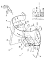
以下、本発明を実施するための形態を図面に基づき説明する。図1,図2において、本実施形態に係る冷却風導入構造Sは、開口部10と、アンダカバー12と、フェンダライナ14と、ダクト部16と、を有している。
Hereinafter, embodiments for carrying out the present invention will be described with reference to the drawings. 1 and 2, the cooling air introduction structure S according to the present embodiment includes an
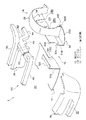
図2において、開口部10は、車両前端の一例たるバンパカバー18に設けられた外気の取入れ口である。この開口部10は、例えば車幅方向に長く形成されている。なお、開口部10の形状はこれに限られず、また開口部10内に整流用のグリル(図示せず)を設けてもよい。
In FIG. 2, an
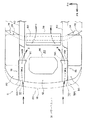
図1から図3において、アンダカバー12は、車両前部20の車両下側に設けられる保護部材及び整流部材であって、例えば該車両前部20のエンジンコンパートメント22の車両下側に取り付けられている。アンダカバー12の車幅方向両端には、車両上方へ延びる縦壁部12Aが設けられている。この縦壁部12Aの上端には、車幅方向外側へ延びる横壁部12Bが設けられている。縦壁部12Aの後端部には、車幅方向内側に傾斜した傾斜面12Cが設けられている。
In FIG. 1 to FIG. 3, the under
図1から図3において、フェンダライナ14は、車両前部20の前輪取付け部24の周囲に設けられる部材であって、該前輪取付け部24の形状に対応したアーチ部26を主体として構成されている。アーチ部26の車幅方向内側端には、前輪取付け部24とエンジンコンパートメント22とを仕切る仕切り部28が設けられている。図1に示されるように、仕切り部28には、例えば、ドライブシャフト32を通すための切欠き28Aと、ステアリングギヤボックス(図示せず)から延びるタイロッド34を通すための切欠き28Bとが形成されている。
1 to 3, the
またアーチ部26の前端下部には、バンパカバー18と、アンダカバー12の縦壁部12Aと、該アーチ部26との間の空間に異物(図示せず)が侵入することを抑制するカバー部30が設けられている。このカバー部30は、底部30Aと、下側縦壁部30Bと、横壁部30Cと、上側縦壁部30Dとを有して構成されている。
Further, a cover portion that suppresses entry of foreign matter (not shown) into the space between the
底部30Aは、略水平、又は車両のアプローチアングルを考慮して車両前方側に向かうに従って車両上方に傾斜している。底部30Aの車両前方側から車幅方向外側にかけての輪郭は、バンパカバー18の車幅方向端部の湾曲形状に対応して、弧状に形成されている。下側縦壁部30Bは、底部30Aの車幅方向内側端から車両上方へ延びている。横壁部30Cは、下側縦壁部30Bの上端から車幅方向外側へ張り出している。そして上側縦壁部30Dは、横壁部30Bの車幅方向外側端から車両上方へ延びて終端している。
The
図1,図3に示されるように、下側縦壁部30B、横壁部30C及び上側縦壁部30Dは、車両正面視でクランク形状をなしている。アーチ部26の前端部の車幅方向内側端は、このクランク形状の車幅方向外側に沿うように形成されている。カバー部30における横壁部30C及び上側縦壁部30Dは、アーチ部26の前端部を跨いで、仕切り部28と車幅方向に重なる位置まで車両後方に延設されている。
As shown in FIGS. 1 and 3, the lower
フェンダライナ14は、アーチ部26及び仕切り部28に、カバー部30を、例えばクリップ(図示せず)を用いて一体化することで構成されている。具体的には、アーチ部26の前端下部には、例えば車両後方側へ張り出したフランジ26Fが設けられており、底部30Aの後端部30Rが、該フランジ26Fの下面に、例えばクリップを用いて連結されている。また上側縦壁部30Dのうち仕切り部28と重なる後端部30Eが、該仕切り部28に、例えばクリップを用いて連結されている。なお、カバー部30、下側縦壁部30B、横壁部30B及び上側縦壁部30Dを、アーチ部26及び仕切り部28に一体成形してもよい。
The
図1,図3に示されるように、カバー部30における底部30Aの下面は、アンダカバー12の下面と略面一とされている。これは、車両前部20の下側における円滑な空気の流れを考慮したものである。また下側縦壁部30Bの高さは、縦壁部12Aの高さよりも低く設定されている。横壁部30Cの幅は、横壁部12Bの幅と例えば同等に設定されている。そして上側縦壁部30Dは横壁部12Bよりも車両上方まで延設されている。
As shown in FIGS. 1 and 3, the bottom surface of the
図1から図3において、ダクト部16は、エンジンコンパートメント22に搭載されるパワーユニット36(図4)の側方に設けられ、アンダカバー12とフェンダライナ14とを組み合わせて構成されている。具体的には、ダクト部16は、縦壁部12A、横壁部12B、横壁部30C及び上側縦壁部30Dにより、断面矩形の筒状に構成されている。ダクト部16は、開口部10に向けて前端16Aが開口し、パワーユニット36の車両後側に配置された被冷却体38に向けて後端16Bが開口している。被冷却体38とは、ラジエータ、空調装置のコンデンサ、ハイブリッド車や電気自動車におけるインバータやモータ等である。
1 to 3, the
カバー部30の下側縦壁部30Bは、アンダカバー12の縦壁部12Aと車幅方向に重なっており、これによってアンダカバー12とカバー部30(フェンダライナ14)とが閉断面化されている。
The lower
図2に示されるように、車両前部20には、車両前後方向に延びるフロントサイドメンバ40が設けられている。図1,図3に示されるように、ダクト部16は、フロントサイドメンバ40の車両下方に、例えば上下に重なるように設けられている。
As shown in FIG. 2, a
フロントサイドメンバ40は、例えばエンジンコンパートメント22の左右に一対設けられている。フロントサイドメンバ40の後端側は、例えば、車両後方側に向かって斜め下方に傾斜する傾斜部42を経由して、車室(図示せず)の左右下部に設けられるサイドメンバ44へと連なっている。フロントサイドメンバ40の後部には、例えばサスペンションメンバ(図示せず)を取り付けるためのマウント部46が、車両下方に突出形成されている。またフロントサイドメンバ40の前端には、車幅方向に延びるバンパリインフォースメント48が取り付けられている。フロントサイドメンバ40の後部の車両上側には、車幅方向に延びるダッシュクロスメンバ50が設けられている。なお、フロントサイドメンバ40の周辺の車体構造は、これに限られない。
A pair of
ダクト部16の後端の側壁部には、車幅方向中央側に向けて傾斜するガイド部16Cが設けられている。このダクト部16は、例えば、アンダカバー12の縦壁部12Aの後端部に設けられた傾斜面12Cである。
A
カバー部30の下側縦壁部30Bをアンダカバー12の縦壁部12Aに接合し、横壁部12Bの車幅方向外側端部にフランジ(図示せず)を設けて、該フランジを上側縦壁部30Dに接合することで、ダクト部16を閉断面構造とすることも可能である。
The lower
(作用)
本実施形態は、上記のように構成されており、以下その作用について説明する。図1,図4において、本実施形態に係る冷却風導入構造Sでは、エンジンコンパートメント22に搭載されるパワーユニット36の側方に、アンダカバー12とフェンダライナ14とを組み合わせて構成されるダクト部16が設けられている。ダクト部16の前端16Aは、車両前端におけるバンパカバー18の開口部10に向けて開口し、後端16Bは、パワーユニット36の車両後側に配置された被冷却体38に向けて後端16Bが開口している。従って、開口部10から矢印A方向に取り入れられた外気は、パワーユニット36に遮られることなく、ダクト部16を通じて、被冷却体38に導入される。このため、パワーユニット36の車両後側に配置される被冷却体38に対し、外気を良好に導くことができる。
(Function)
This embodiment is configured as described above, and the operation thereof will be described below. 1 and 4, in the cooling air introduction structure S according to the present embodiment, a
このとき、ダクト部16の後端16Bの側壁部に設けられたガイド部16Cにより、ダクト部16の後端16Bから車両後方に流れ出る外気の流れが、車幅方向内側に矢印B方向に偏向する。これにより、車両前方にパワーユニット36が位置しているため外気を導入し難い被冷却体38の車幅方向中央部に、より多くの外気を導入できる。そしてこの外気が、被冷却体38を矢印C方向に通過することで、該被冷却体38を効率的に冷却することができる。
At this time, the flow of outside air flowing out from the
ダクト部16は、フロントサイドメンバ40の車両下方に設けられているので、該フロントサイドメンバ40の車両下方のデッドスペースを有効に利用することができる。
Since the
これに加えて、図1,図3に示されるように、本実施形態では、アンダカバー12及びカバー部30(フェンダライナ14)が閉断面化されていることから、前輪(図示せず)が跳ね上げる石や泥等の異物(図示せず)に対する剛性が高まっており、該異物がエンジンコンパートメント22内へ侵入し難い。従って、該異物により被冷却体38が傷つくことを抑制する性能、いわゆる耐チッピング性能を向上させることができる。
In addition to this, as shown in FIGS. 1 and 3, in this embodiment, since the
またこの閉断面化により、エンジンコンパートメント22とその車両側方との間に、アンダカバー12の縦壁部12Aと、カバー部30の下側縦壁部30B及び横壁部30Cとからなる2枚の壁部が存在することとなるため、エンジンコンパートメント22内で発生するエンジン音等が、車外に伝わり難くなる。このため、車外騒音の低減効果が得られる。
In addition, by this closed cross-section, between the
(他の実施形態)
上記実施形態では、開口部10が設けられる車両前端の一例として、バンパカバー18を挙げたが、車両前端はこれに限られない。またダクト部16がフロントサイドメンバ40の車両下方に設けられるものとしたが、ダクト部16の配置はこれに限られるものではなく、例えばダクト部16を、フロントサイドメンバ40の車両上方や車幅方向内側等に設けてもよい。
(Other embodiments)
In the said embodiment, although the
ダクト部16の後端のガイド部16Cの構成は、上記のものに限られず、例えばカバー部30の上側縦壁部30Dの後端部に、車幅方向中央側に向けて傾斜する傾斜面を設けてもよい(図示せず)。ダクト部16の車両後方に、サスペンション等の部品(図示せず)が存在する場合には、ダクト部16の後端16Bから車両後方に流れ出る外気を、該部品により車幅方向中央側へ偏向させることも可能である。従って、このような場合には、ダクト部16の後端にガイド部16Cを設けない構成としてもよい。
The configuration of the
ダクト部16は、断面矩形のものに限られない。またダクト部16は、閉断面構造のものに限られず、開断面構造であっても、実質的に被冷却体38に外気を導入できるものであればよい。
The
10 開口部
12 アンダカバー
14 フェンダライナ
16 ダクト部
16A 前端
16B 後端
16C ガイド部
18 バンパカバー(車両前端)
20 車両前部
22 エンジンコンパートメント
24 前輪取付け部
36 パワーユニット
38 被冷却体
40 フロントサイドメンバ
S 冷却風導入構造
DESCRIPTION OF
DESCRIPTION OF
Claims (3)
車両前部の車両下側に設けられるアンダカバーと、
前記車両前部の前輪取付け部の周囲に設けられるフェンダライナと、
前記車両前部のエンジンコンパートメントに搭載されるパワーユニットの側方に設けられ、前記アンダカバーと前記フェンダライナとを組み合わせて構成され、前記開口部に向けて前端が開口し、前記パワーユニットの車両後側に配置された被冷却体に向けて後端が開口するダクト部と、
を有する冷却風導入構造。 An opening provided at the front end of the vehicle;
An under cover provided on the lower side of the vehicle at the front of the vehicle;
A fender liner provided around a front wheel mounting portion at the front of the vehicle;
Provided on the side of the power unit mounted in the engine compartment at the front of the vehicle, and configured by combining the under cover and the fender liner, the front end opening toward the opening, and the vehicle rear side of the power unit A duct portion whose rear end is open toward the object to be cooled,
Cooling air introduction structure having
Priority Applications (1)
| Application Number | Priority Date | Filing Date | Title |
|---|---|---|---|
| JP2011049186A JP5630331B2 (en) | 2011-03-07 | 2011-03-07 | Cooling air introduction structure |
Applications Claiming Priority (1)
| Application Number | Priority Date | Filing Date | Title |
|---|---|---|---|
| JP2011049186A JP5630331B2 (en) | 2011-03-07 | 2011-03-07 | Cooling air introduction structure |
Publications (2)
| Publication Number | Publication Date |
|---|---|
| JP2012183945A JP2012183945A (en) | 2012-09-27 |
| JP5630331B2 true JP5630331B2 (en) | 2014-11-26 |
Family
ID=47014407
Family Applications (1)
| Application Number | Title | Priority Date | Filing Date |
|---|---|---|---|
| JP2011049186A Expired - Fee Related JP5630331B2 (en) | 2011-03-07 | 2011-03-07 | Cooling air introduction structure |
Country Status (1)
| Country | Link |
|---|---|
| JP (1) | JP5630331B2 (en) |
Families Citing this family (4)
| Publication number | Priority date | Publication date | Assignee | Title |
|---|---|---|---|---|
| DE102013209867A1 (en) * | 2013-05-28 | 2014-12-18 | Bayerische Motoren Werke Aktiengesellschaft | Motor vehicle with outgoing from a wheel housing air duct |
| KR102128051B1 (en) * | 2013-07-23 | 2020-06-29 | 현대모비스 주식회사 | Reduction device of air fluid for vehicles |
| JP6683391B2 (en) * | 2015-07-03 | 2020-04-22 | 株式会社Subaru | Engine bunch cooling structure |
| GB201519863D0 (en) * | 2015-11-11 | 2015-12-23 | Fageir Mazin M L | Assisted air induction apparatus |
Family Cites Families (5)
| Publication number | Priority date | Publication date | Assignee | Title |
|---|---|---|---|---|
| JPH0547697Y2 (en) * | 1987-04-01 | 1993-12-16 | ||
| JPH0173471U (en) * | 1987-11-06 | 1989-05-17 | ||
| JP2528552Y2 (en) * | 1990-03-30 | 1997-03-12 | 富士重工業株式会社 | Car body front structure |
| JPH1059215A (en) * | 1996-08-13 | 1998-03-03 | Nissan Motor Co Ltd | Fitting part construction of front fender protector |
| JP4779420B2 (en) * | 2005-04-22 | 2011-09-28 | 日産自動車株式会社 | Hood flip-up device |
-
2011
- 2011-03-07 JP JP2011049186A patent/JP5630331B2/en not_active Expired - Fee Related
Also Published As
| Publication number | Publication date |
|---|---|
| JP2012183945A (en) | 2012-09-27 |
Similar Documents
| Publication | Publication Date | Title |
|---|---|---|
| JP4627459B2 (en) | Vehicle front structure | |
| JP7006416B2 (en) | Floor undercover | |
| JP6477762B2 (en) | Front body structure of the vehicle | |
| JP5768930B2 (en) | Air guide structure | |
| JP2007062454A (en) | Tractor | |
| JP5545228B2 (en) | Engine intake structure | |
| JP5630331B2 (en) | Cooling air introduction structure | |
| JP5494584B2 (en) | Automobile battery cooling structure | |
| JP4563869B2 (en) | Automobile intake structure | |
| JP5482510B2 (en) | Underfloor structure of the vehicle | |
| JP7234515B2 (en) | Body front structure | |
| JP6288032B2 (en) | Vehicle skeleton structure | |
| JP5778003B2 (en) | Motor drive vehicle | |
| JP2020196367A (en) | Front-end structure | |
| JP5338230B2 (en) | Driving wind introduction structure at the front of the vehicle body | |
| JP5032142B2 (en) | Motorcycle | |
| JP5402827B2 (en) | Cooling air introduction structure | |
| JP2015145150A (en) | vehicle front structure | |
| JP2011173568A (en) | Cowl structure of automobile | |
| JP2010228711A (en) | Vehicular front body structure | |
| JP2013100023A (en) | Vehicle front structure | |
| JP6763828B2 (en) | Body undercover structure | |
| JP2020196368A (en) | Front end structure | |
| JP2016137824A (en) | undercover | |
| JP2016055751A (en) | Undercover structure of vehicle |
Legal Events
| Date | Code | Title | Description |
|---|---|---|---|
| A521 | Request for written amendment filed |
Free format text: JAPANESE INTERMEDIATE CODE: A523 Effective date: 20130118 |
|
| A621 | Written request for application examination |
Free format text: JAPANESE INTERMEDIATE CODE: A621 Effective date: 20131028 |
|
| A977 | Report on retrieval |
Free format text: JAPANESE INTERMEDIATE CODE: A971007 Effective date: 20140814 |
|
| TRDD | Decision of grant or rejection written | ||
| A01 | Written decision to grant a patent or to grant a registration (utility model) |
Free format text: JAPANESE INTERMEDIATE CODE: A01 Effective date: 20140909 |
|
| A61 | First payment of annual fees (during grant procedure) |
Free format text: JAPANESE INTERMEDIATE CODE: A61 Effective date: 20140922 |
|
| R151 | Written notification of patent or utility model registration |
Ref document number: 5630331 Country of ref document: JP Free format text: JAPANESE INTERMEDIATE CODE: R151 |
|
| LAPS | Cancellation because of no payment of annual fees |