JP5625217B2 - Network management system and management computer - Google Patents
Network management system and management computer Download PDFInfo
- Publication number
- JP5625217B2 JP5625217B2 JP2011148173A JP2011148173A JP5625217B2 JP 5625217 B2 JP5625217 B2 JP 5625217B2 JP 2011148173 A JP2011148173 A JP 2011148173A JP 2011148173 A JP2011148173 A JP 2011148173A JP 5625217 B2 JP5625217 B2 JP 5625217B2
- Authority
- JP
- Japan
- Prior art keywords
- packet relay
- relay device
- network
- identifier
- virtual
- Prior art date
- Legal status (The legal status is an assumption and is not a legal conclusion. Google has not performed a legal analysis and makes no representation as to the accuracy of the status listed.)
- Active
Links
Images


Classifications
-
- H—ELECTRICITY
- H04—ELECTRIC COMMUNICATION TECHNIQUE
- H04L—TRANSMISSION OF DIGITAL INFORMATION, e.g. TELEGRAPHIC COMMUNICATION
- H04L12/00—Data switching networks
- H04L12/28—Data switching networks characterised by path configuration, e.g. LAN [Local Area Networks] or WAN [Wide Area Networks]
- H04L12/46—Interconnection of networks
- H04L12/4641—Virtual LANs, VLANs, e.g. virtual private networks [VPN]
-
- H—ELECTRICITY
- H04—ELECTRIC COMMUNICATION TECHNIQUE
- H04L—TRANSMISSION OF DIGITAL INFORMATION, e.g. TELEGRAPHIC COMMUNICATION
- H04L41/00—Arrangements for maintenance, administration or management of data switching networks, e.g. of packet switching networks
- H04L41/08—Configuration management of networks or network elements
- H04L41/0803—Configuration setting
- H04L41/0806—Configuration setting for initial configuration or provisioning, e.g. plug-and-play
-
- H—ELECTRICITY
- H04—ELECTRIC COMMUNICATION TECHNIQUE
- H04L—TRANSMISSION OF DIGITAL INFORMATION, e.g. TELEGRAPHIC COMMUNICATION
- H04L41/00—Arrangements for maintenance, administration or management of data switching networks, e.g. of packet switching networks
- H04L41/08—Configuration management of networks or network elements
- H04L41/0895—Configuration of virtualised networks or elements, e.g. virtualised network function or OpenFlow elements
-
- H—ELECTRICITY
- H04—ELECTRIC COMMUNICATION TECHNIQUE
- H04L—TRANSMISSION OF DIGITAL INFORMATION, e.g. TELEGRAPHIC COMMUNICATION
- H04L41/00—Arrangements for maintenance, administration or management of data switching networks, e.g. of packet switching networks
- H04L41/40—Arrangements for maintenance, administration or management of data switching networks, e.g. of packet switching networks using virtualisation of network functions or resources, e.g. SDN or NFV entities
Description
本発明は、複数のパケット中継装置を管理するネットワーク管理システムにおいて、パケット中継装置が生成する仮想的なパケット中継装置によって提供される仮想的なネットワークを管理するネットワーク管理システムに関する。 The present invention relates to a network management system for managing a plurality of packet relay devices, and managing a virtual network provided by a virtual packet relay device generated by the packet relay device.
従来、一台のパケット中継装置は物理的な一台のパケット中継装置として運用されることが多かった。近年、パケット中継装置の仮想化に関する技術として、VR(Virtual Router)技術及びVRF(Virtual Routing and Forwarding)技術が多用される。ここで、VR技術とは、一台のパケット中継装置を仮想的に複数の領域に分割する技術である。また、VRF技術とは、一台のパケット中継装置内に仮想的に複数のルーティングテーブルを稼動させることによって、一台のパケット中継装置を仮想的に複数台の装置として運用する技術である。この場合、仮想的に分割したそれぞれの領域や、仮想的に稼動させているそれぞれのルーティングテーブルに、ネットワーク管理者が任意の識別子を設定し、この識別子に基づいてネットワークの管理をする。 Conventionally, one packet relay apparatus is often operated as one physical packet relay apparatus. In recent years, VR (Virtual Router) technology and VRF (Virtual Routing and Forwarding) technology are frequently used as technologies related to virtualization of packet relay apparatuses. Here, the VR technology is a technology that virtually divides one packet relay device into a plurality of regions. The VRF technology is a technology for operating one packet relay device virtually as a plurality of devices by virtually operating a plurality of routing tables in one packet relay device. In this case, the network administrator sets an arbitrary identifier in each virtually divided area or each virtually operating routing table, and manages the network based on this identifier.
一台のパケット中継装置を、仮想的に複数台の装置(仮想パケット中継装置)として運用する目的は、これらの仮想的パケット中継装置を連結することによって、一つの物理的なネットワークを複数の仮想的なネットワークとして運用することである。このとき、識別子の付与方法によって、運用管理のスタイルは次の2つとなる。 The purpose of operating one packet relay device virtually as a plurality of devices (virtual packet relay devices) is to connect one virtual network to multiple virtual networks by connecting these virtual packet relay devices. It is to operate as a typical network. At this time, depending on the method of assigning identifiers, there are the following two management styles.
一つ目のスタイルは、連結する仮想的なパケット中継装置に同一の識別子を付与し、連結する仮想パケット中継装置の間で識別子を交換して、相手が同一の仮想ネットワークに属するメンバであるか否か判定するスタイルである。このスタイルの代表的な例としては、VLAN、MPLS+BGP、及びVRF+BGPからなるVPNがある。 The first style is to assign the same identifier to the connected virtual packet relay device, exchange the identifier between the connected virtual packet relay devices, and whether the partner is a member belonging to the same virtual network. This is a style for determining whether or not. A typical example of this style is a VPN consisting of VLAN, MPLS + BGP, and VRF + BGP.
二つ目のスタイルは、連結する仮想的なパケット中継装置の間で識別子を交換せず、連結する仮想的なパケット中継装置に任意の識別子を付与するスタイルである。このスタイルの代表的な例としては、BGPを使用しないVR及びVRFがある。このスタイルでは、BGPが不要で、また識別子の設定も任意となるので、仮想ネットワークを安価かつ容易に構築できる一方、同一の仮想ネットワークに属する仮想パケット中継装置に不統一な識別子が付与され、異なる仮想ネットワークに属する仮想パケット中継装置でありながら、同じ識別子が付与されることがある。 The second style is a style in which an identifier is assigned to a connected virtual packet relay device without exchanging identifiers between the connected virtual packet relay devices. Typical examples of this style include VR and VRF that do not use BGP. In this style, BGP is not required and the setting of the identifier is also arbitrary, so that a virtual network can be constructed inexpensively and easily, while an unidentified identifier is assigned to virtual packet relay devices belonging to the same virtual network and is different. The same identifier may be given even though the virtual packet relay device belongs to a virtual network.
二つ目のスタイルでは、ネットワーク管理者は、各仮想パケット中継装置に付与されている識別子を参照しただけでは、実際の仮想ネットワークの構成を特定できない。また、ネットワーク管理者は、仮想ネットワークを構築する場合、誤って異なる仮想ネットワークに属する仮想パケット中継装置を連結することのないよう、各仮想パケット中継装置に付与されている識別子以外の情報(VLAN ID又はパケット送受信ポート識別子)も意識しつつ、各仮想パケット中継装置を連結する必要がある。 In the second style, the network administrator cannot specify the actual virtual network configuration only by referring to the identifier assigned to each virtual packet relay device. In addition, when constructing a virtual network, the network administrator, in order to prevent accidental connection of virtual packet relay apparatuses belonging to different virtual networks, information other than the identifier assigned to each virtual packet relay apparatus (VLAN ID) Alternatively, it is necessary to connect the virtual packet relay apparatuses while being aware of the packet transmission / reception port identifier).
このため、ネットワーク管理者は、仮想ネットワーク単位に、仮想ネットワークを構成する各仮想パケット中継装置に付与されている識別子と、仮想パケット中継装置の接続関係(VLAN ID又はパケット送受信ポート識別子)を管理しておく作業が必要となる。これらの作業は、ネットワーク管理者が人為的にするには煩雑な作業である。 For this reason, the network administrator manages the identifier assigned to each virtual packet relay device constituting the virtual network and the connection relationship (VLAN ID or packet transmission / reception port identifier) of the virtual packet relay device for each virtual network. Work to keep is necessary. These operations are troublesome for the network manager to be artificial.
本発明は、ネットワーク管理者が仮想パケット中継装置の識別子を意識せずに、仮想ネットワークを管理できるネットワーク管理システムを提供することを目的とする。 An object of the present invention is to provide a network management system in which a network administrator can manage a virtual network without being aware of the identifier of the virtual packet relay device.
本発明の代表的な一例を示せば、ネットワークを構成する複数のパケット中継装置と、前記ネットワークの構成を表示する表示装置と、を備え、前記複数のパケット中継装置を管理するネットワーク管理システムであって、前記パケット中継装置は、少なくとも一つの仮想パケット中継装置を生成可能であって、前記複数のパケット中継装置に生成された仮想パケット中継装置は、複数の仮想的な第1ネットワークを提供し、前記仮想パケット中継装置には、当該仮想パケット中継装置が生成されたパケット中継装置内で一意な仮想パケット中継装置識別子が付与され、前記各第1ネットワークは、少なくとも一つ以上の仮想的な第2ネットワークに分割可能であって、前記パケット中継装置は、自身に付与された仮想パケット中継装置識別子及び前記第2ネットワークの識別子である第2ネットワーク識別子を構成情報として管理し、前記ネットワーク管理システムは、前記パケット中継装置から構成情報を取得し、前記取得した構成情報を構成情報管理テーブルに格納する構成情報取得部と、前記構成情報取得部が前記パケット中継装置から構成情報を取得した場合、前記取得した構成情報に含まれる仮想パケット中継装置識別子が属する第1ネットワークを特定し、前記取得した構成情報と前記特定した第1ネットワークの識別子である第1ネットワーク識別子とを対応付けて第1ネットワーク構成テーブルに登録する第1ネットワーク特定部と、所定の第1ネットワークの構成を表示する表示要求を受け付けた場合、前記第1ネットワーク構成テーブルを参照し、前記所定の第1ネットワークの構成を前記表示装置に表示するネットワーク構成表示部と、を備え、前記第1ネットワーク特定部は、前記構成情報取得部が前記パケット中継装置から構成情報を取得した場合、前記取得した構成情報から仮想パケット中継装置識別子、及び第2ネットワーク識別子を抽出し、前記抽出した第2ネットワーク識別子に対応する前記第2ネットワーク識別子が付与された仮想パケット中継装置の仮想パケット中継装置識別子が前記第1ネットワーク構成テーブルに登録されているか否かを判定し、前記抽出した第2ネットワーク識別子に対応する前記第2ネットワーク識別子が付与された仮想パケット中継装置の仮想パケット中継装置識別子が前記第1ネットワーク構成テーブルに登録されていないと判定された場合、新たな第1ネットワーク識別子を生成し、前記生成した第1ネットワーク識別子と前記取得した構成情報とを対応付けて前記第1ネットワーク構成テーブルに登録し、前記抽出した第2ネットワーク識別子に対応する前記第2ネットワーク識別子が付与された仮想パケット中継装置の仮想パケット中継装置識別子が前記第1ネットワーク構成テーブルに登録されていると判定された場合、当該仮想パケット中継装置識別子に対応付けられている前記第1ネットワーク識別子と前記取得した構成情報とを対応付けて前記第1ネットワーク構成テーブルに登録し、前記ネットワーク構成表示部は、前記表示要求を受け付けた場合、前記第1仮想ネットワーク構成テーブルを参照し、前記所定の第1ネットワーク識別子に対応付けられる仮想パケット中継装置識別子を特定することによって、前記所定の第1ネットワークの構成を特定し、前記特定された所定の第1ネットワークの構成を前記表示装置に表示することを特徴とする。 A typical example of the present invention is a network management system that includes a plurality of packet relay devices that configure a network and a display device that displays the network configuration, and manages the plurality of packet relay devices. The packet relay device can generate at least one virtual packet relay device, and the virtual packet relay device generated by the plurality of packet relay devices provides a plurality of virtual first networks, The virtual packet relay device is given a virtual packet relay device identifier that is unique within the packet relay device in which the virtual packet relay device is generated, and each of the first networks has at least one or more virtual second relays. The packet relay device can be divided into networks, and the virtual packet relay device identification assigned to itself And a second network identifier that is an identifier of the second network is managed as configuration information, and the network management system acquires configuration information from the packet relay device and stores the acquired configuration information in a configuration information management table When the configuration information acquisition unit and the configuration information acquisition unit acquire configuration information from the packet relay device, the first network to which the virtual packet relay device identifier included in the acquired configuration information belongs is specified and the acquired configuration A first network specifying unit for registering the information and the first network identifier, which is the identifier of the specified first network, in association with the first network configuration table, and a display request for displaying a predetermined first network configuration The first network configuration table is referred to, the predetermined network A network configuration display unit that displays the configuration of the first network on the display device, and the first network specifying unit acquires the configuration information when the configuration information acquisition unit acquires configuration information from the packet relay device. The virtual packet relay device identifier and the second network identifier are extracted from the configuration information, and the virtual packet relay device identifier of the virtual packet relay device to which the second network identifier corresponding to the extracted second network identifier is assigned is the first packet identifier. It is determined whether or not it is registered in one network configuration table, and the virtual packet relay device identifier of the virtual packet relay device to which the second network identifier corresponding to the extracted second network identifier is assigned is the first network configuration If it is determined that it is not registered in the table, Generating a first network identifier, registering the generated first network identifier and the obtained configuration information in association with each other in the first network configuration table, and corresponding to the extracted second network identifier. When it is determined that the virtual packet relay device identifier of the virtual packet relay device to which the network identifier is assigned is registered in the first network configuration table, the first network associated with the virtual packet relay device identifier An identifier and the acquired configuration information are associated with each other and registered in the first network configuration table. When the network configuration display unit receives the display request, the network configuration display unit refers to the first virtual network configuration table, and In a virtual packet associated with the first network identifier of By identifying the device identifier to identify the configuration of the predetermined first network, and displaying the configuration of the identified predetermined first network to the display device.
本発明によれば、ネットワーク管理者が仮想パケット中継装置の識別子を意識せずに、仮想ネットワークを管理できるネットワーク管理システムを提供できる。 According to the present invention, it is possible to provide a network management system that allows a network administrator to manage a virtual network without being aware of the identifier of the virtual packet relay device.
(第1実施形態)
第1実施形態について図1〜図11を用いて説明する。
(First embodiment)
A first embodiment will be described with reference to FIGS.
図1は、本発明の第1実施形態のネットワーク管理システムのネットワーク構成図である。 FIG. 1 is a network configuration diagram of a network management system according to a first embodiment of this invention.
ネットワーク管理システムは、複数のパケット中継装置10a〜10d(以下、総称してパケット中継装置10という)、及び管理計算機30を備える。複数のパケット中継装置10及び管理計算機30は、インターネット40に接続される。
The network management system includes a plurality of
本発明の代表的な一例を示せば、ネットワークを構成する複数のパケット中継装置と、前記ネットワークの構成を表示する表示装置と、を備え、前記複数のパケット中継装置を管理するネットワーク管理システムであって、前記パケット中継装置は、少なくとも一つの仮想パケット中継装置を生成可能であって、前記複数のパケット中継装置に生成された仮想パケット中継装置は、複数の仮想的な第1ネットワークを提供し、前記仮想パケット中継装置には、当該仮想パケット中継装置が生成されたパケット中継装置内で一意な仮想パケット中継装置識別子が付与され、前記各第1ネットワークは、少なくとも一つ以上の仮想的な第2ネットワークに分割可能であって、前記パケット中継装置は、自身に付与された仮想パケット中継装置識別子及び前記第2ネットワークの識別子である第2ネットワーク識別子を構成情報として管理し、前記ネットワーク管理システムは、前記パケット中継装置から構成情報を取得し、前記取得した構成情報を構成情報管理テーブルに格納する構成情報取得部と、前記構成情報取得部が前記パケット中継装置から構成情報を取得した場合、前記取得した構成情報に含まれる仮想パケット中継装置識別子が属する第1ネットワークを特定し、前記取得した構成情報と前記特定した第1ネットワークの識別子である第1ネットワーク識別子とを対応付けて第1ネットワーク構成テーブルに登録する第1ネットワーク特定部と、所定の第1ネットワークの構成を表示する表示要求を受け付けた場合、前記第1ネットワーク構成テーブルを参照し、前記所定の第1ネットワークの構成を前記表示装置に表示するネットワーク構成表示部と、を備え、前記第1ネットワーク特定部は、前記構成情報取得部が前記パケット中継装置から構成情報を取得した場合、前記取得した構成情報から仮想パケット中継装置識別子、及び第2ネットワーク識別子を抽出し、前記抽出した第2ネットワーク識別子に対応する前記第2ネットワーク識別子が付与された仮想パケット中継装置の仮想パケット中継装置識別子が前記第1ネットワーク構成テーブルに登録されているか否かを判定し、前記抽出した第2ネットワーク識別子に対応する前記第2ネットワーク識別子が付与された仮想パケット中継装置の仮想パケット中継装置識別子が前記第1ネットワーク構成テーブルに登録されていないと判定された場合、新たな第1ネットワーク識別子を生成し、前記生成した第1ネットワーク識別子と前記取得した構成情報とを対応付けて前記第1ネットワーク構成テーブルに登録し、前記抽出した第2ネットワーク識別子に対応する前記第2ネットワーク識別子が付与された仮想パケット中継装置の仮想パケット中継装置識別子が前記第1ネットワーク構成テーブルに登録されていると判定された場合、当該仮想パケット中継装置識別子に対応付けられている前記第1ネットワーク識別子と前記取得した構成情報とを対応付けて前記第1ネットワーク構成テーブルに登録し、前記ネットワーク構成表示部は、前記表示要求を受け付けた場合、前記第1ネットワーク構成テーブルを参照し、前記所定の第1ネットワーク識別子に対応付けられる仮想パケット中継装置識別子を特定することによって、前記所定の第1ネットワークの構成を特定し、前記特定された所定の第1ネットワークの構成を前記表示装置に表示することを特徴とする。 A typical example of the present invention is a network management system that includes a plurality of packet relay devices that configure a network and a display device that displays the network configuration, and manages the plurality of packet relay devices. The packet relay device can generate at least one virtual packet relay device, and the virtual packet relay device generated by the plurality of packet relay devices provides a plurality of virtual first networks, The virtual packet relay device is given a virtual packet relay device identifier that is unique within the packet relay device in which the virtual packet relay device is generated, and each of the first networks has at least one or more virtual second relays. The packet relay device can be divided into networks, and the virtual packet relay device identification assigned to itself And a second network identifier that is an identifier of the second network is managed as configuration information, and the network management system acquires configuration information from the packet relay device and stores the acquired configuration information in a configuration information management table When the configuration information acquisition unit and the configuration information acquisition unit acquire configuration information from the packet relay device, the first network to which the virtual packet relay device identifier included in the acquired configuration information belongs is specified and the acquired configuration A first network specifying unit for registering the information and the first network identifier, which is the identifier of the specified first network, in association with the first network configuration table, and a display request for displaying a predetermined first network configuration The first network configuration table is referred to, the predetermined network A network configuration display unit that displays the configuration of the first network on the display device, and the first network specifying unit acquires the configuration information when the configuration information acquisition unit acquires configuration information from the packet relay device. The virtual packet relay device identifier and the second network identifier are extracted from the configuration information, and the virtual packet relay device identifier of the virtual packet relay device to which the second network identifier corresponding to the extracted second network identifier is assigned is the first packet identifier. It is determined whether or not it is registered in one network configuration table, and the virtual packet relay device identifier of the virtual packet relay device to which the second network identifier corresponding to the extracted second network identifier is assigned is the first network configuration If it is determined that it is not registered in the table, Generating a first network identifier, registering the generated first network identifier and the obtained configuration information in association with each other in the first network configuration table, and corresponding to the extracted second network identifier. When it is determined that the virtual packet relay device identifier of the virtual packet relay device to which the network identifier is assigned is registered in the first network configuration table, the first network associated with the virtual packet relay device identifier in association with the identifier and the acquired configuration information registered in the first network configuration table, the network configuration display unit, when receiving the display request, by referring to the first network configuration table, the predetermined Virtual packet relay device associated with the first network identifier of By identifying the identifier to identify the configuration of the predetermined first network, and displaying the configuration of the identified predetermined first network to the display device.
図1では、パケット中継装置10aとパケット中継装置10bとが相互に接続され、パケット中継装置10cはパケット中継装置10aに接続され、パケット中継装置10dはパケット中継装置10bに接続される。
In FIG. 1, a
パケット中継装置10は、自身に仮想的な仮想パケット中継装置20a〜20d(以下、総称して、仮想パケット中継装置20という)を生成する。仮想パケット中継装置20は、パケット中継装置10を複数台の装置に分割することによって実現されてもよいし、パケット中継装置10が複数の仮想的なルーティングテーブルを保持することによって実現されてもよい。
The
図1では、パケット中継装置10a上で仮想パケット中継装置20a及び20bが動作し、パケット中継装置10b上で仮想パケット中継装置20c及び20dが動作し、パケット中継装置10c上で仮想パケット中継装置20eが動作している。
In FIG. 1, the virtual packet relay devices 20a and 20b operate on the
各仮想パケット中継装置20同士が接続されることによって、一つの物理ネットワーク上に仮想的な複数のネットワーク(第1ネットワーク)が構築される。
By connecting the virtual
図1では、仮想パケット中継装置20a、20c、及び20eが接続され、一つの仮想ネットワーク(以下、仮想ネットワークAという)が構築される。具体的には、仮想パケット中継装置20aと仮想パケット中継装置20cとが相互に接続され、仮想パケット中継装置20eは仮想パケット中継装置20aに接続される。 In FIG. 1, virtual packet relay apparatuses 20a, 20c, and 20e are connected to form one virtual network (hereinafter referred to as virtual network A). Specifically, the virtual packet relay device 20a and the virtual packet relay device 20c are connected to each other, and the virtual packet relay device 20e is connected to the virtual packet relay device 20a.
また、図1では、仮想パケット中継装置20b、20d、及びパケット中継装置10dが接続され、一つの仮想ネットワーク(以下、仮想ネットワークBという)が構築される。具体的には、仮想パケット中継装置20bと仮想パケット中継装置20dとが接続され、パケット中継装置10dは、仮想パケット中継装置20dに接続される。
Further, in FIG. 1, the virtual packet relay devices 20b and 20d and the
以上によって、図1では、一つの物理ネットワーク上に、二つの仮想ネットワークが構築される。 As described above, in FIG. 1, two virtual networks are constructed on one physical network.
ネットワーク管理者は、一の仮想ネットワークを一つの物理ネットワークのように運用できる。また、一つの仮想ネットワークには、少なくとも一つ以上の仮想的なネットワーク(第2ネットワーク)が設定可能である。ここで、第2ネットワークは、例えば、仮想パケット中継装置に設定されるVLAN(Virtual Local Area Network)識別子(VLAN ID)によって構築されるVLANであってもよいし、仮想パケット中継装置20とパケット送受信ポート14(図2参照)とが対応付けられることによって構築される仮想的なネットワークであってもよい。
The network administrator can operate one virtual network as one physical network. In addition, at least one virtual network (second network) can be set in one virtual network. Here, the second network may be, for example, a VLAN constructed by a VLAN (Virtual Local Area Network) identifier (VLAN ID) set in the virtual packet relay device, or may transmit and receive packets with the virtual
なお、第2ネットワークがVLANである場合について本実施形態で説明し、第2ネットワークが、仮想パケット中継装置20とパケット送受信ポート14とが対応付けられることによって構築される場合については、第2実施形態で説明する。
The case where the second network is a VLAN will be described in the present embodiment, and the case where the second network is constructed by associating the virtual
図1では、仮想ネットワークA内にはVLAN ID10及び100によって識別される二つのVLANが設定される。仮想パケット中継装置20aにはVLAN ID10及び100が設定され、仮想パケット中継装置20cにはVLAN ID10が設定され、仮想パケット中継装置20cにはVLAN ID100が設定される。
In FIG. 1, two VLANs identified by
また、仮想ネットワークB内にはVLAN ID20及び200によって識別される二つのVLANが設定される。仮想パケット中継装置20bにはVLAN ID20及び200が設定され、仮想パケット中継装置20dにはVLAN ID20及び200が設定され、パケット中継装置10dにはVLAN ID200が設定される。
In the virtual network B, two VLANs identified by
VLAN IDが設定された仮想パケット中継装置20又はパケット中継装置10は、自身に設定されたVLAN IDを含むパケットのみを受信し、自身に設定されたVLAN IDをパケットに含ませてパケットを送信する。これによって、一つの仮想ネットワークがVLAN IDによって少なくとも一つ以上のVLANに分割される。
The virtual
管理計算機30は、インターネット40を介してパケット中継装置10にアクセスし、パケット中継装置10に設定された構成情報(図2に示すコンフィグレーション23)を取得し、又はパケット中継装置10の構成情報を設定する。構成情報は、例えば、パケット中継装置10に生成された仮想パケット中継装置20に付与された仮想パケット中継装置識別子、及び、仮想パケット中継装置20に設定されたVLAN IDを含む。
The
なお、仮想パケット中継装置識別子は、仮想パケット中継装置が生成される場合に付与され、管理計算機30は、仮想パケット中継装置に関する構成情報(VLAN ID)を設定する場合、当該仮想パケット中継装置の仮想パケット中継装置識別子を指定することによって、特定の仮想パケット中継装置を特定する。
The virtual packet relay device identifier is assigned when a virtual packet relay device is generated. When the
仮想ネットワークAを構成する仮想パケット中継装置20aには仮想パケット中継装置識別子100が付与され、仮想ネットワークAを構成する仮想パケット中継装置20cには仮想パケット中継装置識別子100が付与され、仮想ネットワークAを構成する仮想パケット中継装置20eには仮想パケット中継装置識別子200が付与される。
The virtual packet
一方、仮想ネットワークBを構成する仮想パケット中継装置20bには仮想パケット中継装置識別子200が付与され、仮想ネットワークBを構成する仮想パケット中継装置20dには仮想パケット中継装置識別子300が付与される。
On the other hand, the virtual packet
なお、仮想パケット中継装置識別子は、同一のパケット中継装置10内で一意でなければならず、また、パケット中継装置10に予め設定された付与可能なパケット中継装置識別子でなければならない。
The virtual packet relay device identifier must be unique within the same
同一の仮想ネットワークを構成する仮想パケット中継装置に同一の仮想パケット中継装置識別子を付与できれば、仮想ネットワークを識別するために仮想パケット中継装置識別子を用いることができるので、最も効率的である。しかし、上述した事情等によって、同一の仮想ネットワークを構成する仮想パケット中継装置に同一の仮想パケット中継装置識別子を付与できない場合がある。 If the same virtual packet relay device identifier can be assigned to the virtual packet relay device constituting the same virtual network, the virtual packet relay device identifier can be used to identify the virtual network, which is most efficient. However, due to the circumstances described above, the same virtual packet relay device identifier may not be assigned to the virtual packet relay device that constitutes the same virtual network.
例えば、図1では、仮想ネットワークAを構成する仮想パケット中継装置20a及び20eの仮想パケット中継装置識別子は「100」と「200」とで相違しており、仮想ネットワークBを構成する仮想パケット中継装置20b及び20dの仮想パケット中継装置識別子は「200」と「300」とで相違している。 For example, in FIG. 1, the virtual packet relay device identifiers of the virtual packet relay devices 20a and 20e constituting the virtual network A are different between “100” and “200”, and the virtual packet relay device constituting the virtual network B The virtual packet relay device identifiers 20b and 20d are different between “200” and “300”.
この場合、仮想パケット中継装置識別子を仮想ネットワークの識別子と用いることはできず、ネットワーク管理者は、仮想ネットワークを識別するための情報を利用できず、VLAN IDを確認しながら、仮想ネットワークの構成を把握することになる。 In this case, the virtual packet relay device identifier cannot be used as the virtual network identifier, the network administrator cannot use the information for identifying the virtual network, and confirms the VLAN ID while configuring the virtual network configuration. To grasp.
本実施形態では、仮想ネットワークを構成する仮想パケット中継装置の仮想パケット中継装置識別子が異なる場合であっても、仮想パケット中継装置と当該仮想パケット中継装置によって構成される仮想ネットワークとの関係をネットワーク管理者が容易に把握できるネットワーク管理システムについて詳細に説明する。 In the present embodiment, even if the virtual packet relay device identifiers of the virtual packet relay devices constituting the virtual network are different, the network management is performed on the relationship between the virtual packet relay device and the virtual network configured by the virtual packet relay device. A network management system that can be easily grasped by a person will be described in detail.
また、本実施形態では、新たなパケット中継装置10をある仮想ネットワークに追加し、追加したパケット中継装置10に生成される仮想パケット中継装置20の識別子を自動的に設定するネットワーク管理システムについても説明する。
In the present embodiment, a network management system that adds a new
さらに、ある仮想ネットワークのVLAN IDを設定する場合、当該VLAN IDが既に別の仮想ネットワークに設定されている場合、それを検知し、設定を中止できるネットワーク管理システムについても説明する。 Furthermore, when setting the VLAN ID of a certain virtual network, a network management system capable of detecting and canceling the setting when the VLAN ID is already set in another virtual network will be described.
なお、ネットワークの構成、物理ネットワークに構築される仮想ネットワークの数、仮想ネットワークに生成されるVLANの数、及びパケット中継装置10に生成される仮想パケット中継装置20の数は、図1に図示した例に限定されない。
The network configuration, the number of virtual networks constructed in the physical network, the number of VLANs created in the virtual network, and the number of virtual
また、管理計算機30は、一つの計算機で実現されてもよく、複数の計算機によって実現されてもよい。さらに、管理計算機30は、一又は複数のパケット中継装置10によって実現されもよい。
The
図2は、本発明の第1実施形態のパケット中継装置10の構成を示すブロック図である。
FIG. 2 is a block diagram illustrating a configuration of the
パケット中継装置10は、ネットワークインタフェースモジュール11a及び11b(以下、総称してネットワークインタフェースモジュール11)、スイッチングモジュール12、並びに制御モジュール13を備える。
The
ネットワークインタフェースモジュール11について、ネットワークインタフェースモジュール11aを例に説明する。
The
ネットワークインタフェースモジュール11aは、パケット送受信ポート14a及び14b(以下、総称してパケット送受信ポート14)、コントローラ15a、並びにメモリ16aを備える。パケット送受信ポート14には、イーサネットケーブルが物理的に接続される。コントローラ15aは、パケット送受信ポート14を介して受信したパケットを解析し、受信したパケットの宛先を特定する。メモリ16aは、パケット送受信ポート14を介して送受信されるパケットが一時的に記憶されるバッファとして機能する。
The network interface module 11a includes packet transmission /
なお、ネットワークインタフェースモジュール11bは、ネットワークインタフェースモジュール11aと同じ構成であり、パケット送受信ポート14b及び14c、コントローラ15b、並びにメモリ16bを備える。パケット送受信ポート14b及び14cは、パケット送受信ポート14に対応し、コントローラ15bはコントローラ15aに対応し、メモリ16bはメモリ16aに対応する。コントローラ15a及び15bを総称してコントローラ15とする。
The
コントローラ15は、ネットワークインタフェースモジュール11が受信したパケットの宛先が他の装置宛てであるか否かを判定する。
The controller 15 determines whether the destination of the packet received by the
コントローラ15は、受信したパケットが他の装置宛てであると判定した場合、宛先となる装置とパケットの出力するネットワークインタフェースモジュール11及びパケット送受信ポート14とが対応付けられたアドレステーブルを参照し、受信したパケットを出力するネットワークインタフェースモジュール11及びパケット送受信ポート14を特定する。
When the controller 15 determines that the received packet is addressed to another device, the controller 15 refers to the address table in which the destination device, the
そして、コントローラ15は、特定したネットワークインタフェースモジュール11及びパケット送受信ポート14から受信したパケットを転送する。
Then, the controller 15 transfers the packet received from the identified
一方、コントローラ15は、受信したパケットが他の装置宛てでないと判定した場合、つまり、受信したパケットが自装置宛てであると判定した場合、受信したパケットを自装置に備わる制御モジュール13に渡す。
On the other hand, when the controller 15 determines that the received packet is not addressed to another device, that is, when it is determined that the received packet is addressed to the own device, the controller 15 passes the received packet to the
スイッチングモジュール12は、ネットワークインタフェースモジュール11及び制御モジュール13からの指示に基づいて、ネットワークインタフェースモジュール11間、及びネットワークインタフェースモジュール11と制御モジュール13との間の通信路を切り換える。
The
制御モジュール13は、メモリ16c及びCPU17aを備える。メモリ16cは、ソフトウェア処理部18を実現するためのプログラムを記憶し、CPU17aは、メモリ16cに記憶されたプログラムを実行することによって、ソフトウェア処理部18として機能する。
The
ソフトウェア処理部18は、パケット送受信部19、コンフィグレーション管理部21、及びパケット中継装置管理部22を備える。
The
パケット送受信部19は、自装置宛てのパケットの受信、及び、他の装置宛てのパケットの送信の制御を司る。例えば、パケット送受信部19は、自装置宛てのパケットが渡され、当該パケットが管理計算機30から送信された構成情報参照要求(図7参照)又は構成情報設定要求(図9参照)である場合、渡されたパケットをパケット中継装置管理部22に渡す。
The packet transmission /
一方、パケット送受信部19は、パケット中継装置管理部22からパケットが渡された場合、当該パケットを所望の管理計算機30に転送する。なお、パケット中継装置管理部22から渡されるパケットは、構成情報参照要求に対する構成情報参照応答、又は、構成情報設定要求に対する構成情報設定応答である。
On the other hand, when a packet is received from the packet relay
パケット中継装置管理部22は、管理計算機30から送信された構成情報設定要求をパケット送受信部19を介して受信した場合、当該構成情報設定要求を解析し、コンフィグレーション管理部21に構成情報の設定をさせる。なお、構成情報設定要求は、パケット中継装置10の動作に関する種々の項目を設定する要求であり、例えば、仮想パケット中継装置20を新たに生成する要求、仮想パケット中継装置20を削除する要求、VLANを新たに設定する要求、VLANを削除する要求等がある。
When receiving the configuration information setting request transmitted from the
コンフィグレーション管理部21は、コンフィグレーション(構成情報)23を保持し、パケット中継装置管理部22に渡された構成情報設定要求に基づいて、パケット中継装置10の設定を施した後に、当該設定内容をコンフィグレーション23に記録する。
The
コンフィグレーション23には、パケット中継装置10全体の設定情報及びパケット中継装置10全体の状態情報(構成情報)が記録され、例えば、パケット中継装置10で動作する各仮想パケット中継装置の情報、各VLANの情報が記録される。
In the
図3は、本発明の第1実施形態の管理計算機30の構成を示すブロック図である。
FIG. 3 is a block diagram illustrating the configuration of the
管理計算機30は、例えば汎用の計算機によって構成され、ネットワークインタフェース31、ハードディスク32、メモリ16d、CPU17bを備える。
The
ネットワークインタフェース31は、パケットを送受信する物理的なインタフェースである。ハードディスク32は、プログラム等の各種情報を記憶する。
The
メモリ16dは、ソフトウェア処理部33を実現するためのプログラムを記憶し、CPU17bは、メモリ16dに記憶されたプログラムを実行することによって、ソフトウェア処理部33として機能する。
The
パケット送受信部34は、ネットワークインタフェース31を介したパケットの送受信を司る。
The packet transmission /
ネットワーク管理部35は、ネットワーク管理者がパケット中継装置10を管理するためのフロントエンドとして動作するアプリケーションである。ネットワーク管理部35は、パケット中継装置参照部36、仮想ネットワーク構成計算部37、パケット中継装置設定部38、コンフィグレーション生成部39、ユーザインタフェース部41、コンフィグレーション管理データベース42a、及び仮想ネットワーク構成テーブル43aを備える。
The
ユーザインタフェース部41は、ネットワーク管理者が仮想ネットワークの構成を管理するために表示装置44に表示するGUI(グラフィカルユーザインタフェース)の表示データを生成するネットワーク構成表示部であるとともに、ネットワーク管理者による指示をキーボード45及びマウス46を介して受け付ける。ネットワーク管理者による指示には、例えば、ネットワーク構成参照指示、及びパケット中継装置10の構成情報を設定する設定指示等がある。
The
パケット中継装置参照部36は、パケット中継装置10のコンフィグレーション23に記憶された構成情報を取得する要求である参照要求を、パケット中継装置10に送信する。参照要求の送信タイミングは、例えば、新たなパケット中継装置10がネットワークに追加されたことを管理計算機30が検出したタイミングであってもよいし、周期的に送信されてもよいし、管理計算機30がネットワーク管理者からネットワーク構成参照指示を受け付けたタイミングであってもよい。なお、管理計算機30がパケット中継装置10の構成情報を取得する処理の詳細は図7で詳細を説明する。
The packet relay
また、パケット中継装置参照部36は、パケット中継装置10からコンフィグレーション23に記憶された構成情報を取得した場合、取得した構成情報に基づいてコンフィグレーション管理データベース42a(構成情報管理テーブル)を更新する。
Further, when acquiring the configuration information stored in the
このように、パケット中継装置参照部36は、パケット中継装置10から構成情報を取得し、取得した構成情報をコンフィグレーション管理データベース42aに登録するため、構成情報取得部として機能する。
Thus, the packet relay
仮想ネットワーク構成計算部37は、コンフィグレーション管理データベース42a及び仮想ネットワーク構成テーブル43aを参照し、各仮想ネットワークを構成する仮想パケット中継装置、及び当該仮想パケット中継装置の接続関係を特定する。これらの特定処理については、図8A及び図8Bで詳細を説明する。
The virtual network
仮想ネットワーク構成計算部37は、同じ仮想ネットワークを構成する仮想パケット中継装置20に同じ仮想ネットワーク識別子を付与し、当該仮想ネットワーク識別子と当該仮想ネットワーク識別子が付与された仮想パケット中継装置20の構成情報とを対応付けて仮想ネットワーク構成テーブル43aに登録する。
The virtual network
仮想ネットワーク構成計算部37が、仮想ネットワーク構成テーブル43aを参照し、各仮想ネットワークの構成を特定し、ユーザインタフェース部41が、仮想ネットワーク構成計算部37によって特定された仮想ネットワークの構成を表示装置44に描画することによって、ネットワーク管理者が仮想ネットワーク識別子を意識せず、各仮想ネットワークの構成を把握できる。
The virtual network
仮想ネットワーク構成計算部37は、パケット中継装置10から取得した構成情報に含まれる仮想パケット中継装置識別子が属する第1ネットワークを特定し、取得した構成情報と特定した第1ネットワークの識別子である第1ネットワーク識別子(仮想ネットワーク識別子)とを対応付けて第1ネットワーク構成テーブル(仮想ネットワーク構成テーブル43)に登録する第1ネットワーク特定部として機能する。
The virtual network
パケット中継装置設定部38は、ユーザインタフェース部41がネットワーク管理者からのパケット中継装置10の設定指示を受け付けた場合、受け付けた設定指示に対応する設定要求を、パケット中継装置10に送信する。
When the
設定要求は、パケット中継装置10の構成情報を設定する要求であり、例えば、仮想パケット中継装置20の生成要求、仮想パケット中継装置20の削除要求、VLANの設定要求、及びVLANの削除要求等である。パケット中継装置10の構成情報を設定する処理の詳細は、図8〜図10で説明する。
The setting request is a request to set the configuration information of the
また、パケット中継装置設定部38は、設定要求に基づいて構成情報を設定したパケット中継装置10から送信された応答を受信した場合、受信した応答に基づいて、コンフィグレーション管理データベース42aを更新する。
Further, when receiving a response transmitted from the
コンフィグレーション生成部39は、ユーザインタフェース部41がネットワーク管理者からパケット中継装置10の追加指示を受け付けた場合、つまり、既存のパケット中継装置10に新たなパケット中継装置10を追加する指示を受け付けた場合、新たに追加するパケット中継装置10に付与される仮想ネットワーク識別子、及びVLAN IDを決定する。これによって、ネットワーク管理者は、仮想パケット中継装置に付与される仮想ネットワーク識別子及びVLAN IDを意識せず、仮想ネットワークに新たなパケット中継装置10を追加できる。
The
なお、パケット中継装置設定部38は、コンフィグレーション生成部39によって決定された仮想ネットワーク識別子及びVLAN IDが、新たに追加されるパケット中継装置10に設定されるよう、構成情報の設定要求を当該パケット中継装置10に送信する。
The packet relay
そして、コンフィグレーション生成部39は、パケット中継装置設定部38が送信した構成情報の設定要求に対する応答を受信した場合、コンフィグレーション管理データベース42a及び仮想ネットワーク構成テーブル43aを更新する。
When receiving a response to the configuration information setting request transmitted from the packet relay
図4は、本発明の第1実施形態のコンフィグレーション管理データベース42aの説明図である。
FIG. 4 is an explanatory diagram of the
コンフィグレーション管理データベース42aは、パケット中継装置10から取得した構成情報を管理するデータベースであり、パケット中継装置識別子421、仮想パケット中継装置識別子422、及びVLAN ID423を含む。
The
パケット中継装置識別子421には、構成情報を取得したパケット中継装置10の識別子であるパケット中継装置識別子が登録される。仮想パケット中継装置識別子422には、構成情報を取得したパケット中継装置10に生成される仮想パケット中継装置20の識別子である仮想パケット中継装置識別子が登録される。VLAN ID423には、仮想パケット中継装置20に設定されるVLANの識別子であるVLAN IDが登録される。
In the packet
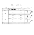
図5は、本発明の第1実施形態の仮想ネットワーク構成テーブル43aの説明図である。 FIG. 5 is an explanatory diagram of the virtual network configuration table 43a according to the first embodiment of this invention.
仮想ネットワーク構成テーブル43aは、仮想ネットワーク識別子と、当該仮想ネットワーク識別子によって識別される仮想ネットワークを構成する仮想パケット中継装置の仮想パケット中継装置識別子と、を対応付けて管理するテーブルである。仮想ネットワーク構成テーブル43aは、仮想ネットワーク識別子431、パケット中継装置識別子432、仮想パケット中継装置識別子433、及びVLAN ID434を含む。
The virtual network configuration table 43a is a table that manages a virtual network identifier and a virtual packet relay device identifier of a virtual packet relay device that configures the virtual network identified by the virtual network identifier in association with each other. The virtual network configuration table 43a includes a
仮想ネットワーク識別子431には、仮想ネットワークの識別子である仮想ネットワーク識別子が登録される。
In the
パケット中継装置識別子432には、当該エントリの仮想ネットワーク識別子に対応付けられた仮想パケット中継装置識別子の仮想パケット中継装置が生成されるパケット中継装置のパケット中継装置識別子が登録される。
Registered in the packet
仮想パケット中継装置識別子433には、当該エントリの仮想ネットワーク識別子に対応付けられた仮想パケット中継装置識別子が登録される。
In the virtual packet
VLAN ID434には、当該エントリの仮想ネットワーク識別子に対応付けられた仮想パケット中継装置識別子の仮想パケット中継装置に設定されたVLANの識別子であるVLAN IDが登録される。
In the
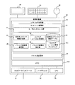
図6は、本発明の第1実施形態の管理計算機30の表示装置44に表示されるネットワーク構成表示画面800の説明図である。
FIG. 6 is an explanatory diagram of the network
ネットワーク構成表示画面800には、図1に示すネットワーク内に構築される仮想ネットワークの構成が表示され、具体的には、パケット中継装置10を示すアイコン及びイーサネットケーブルを示すアイコンによって仮想ネットワークのネットワークトポロジが表示される。
The network
ネットワーク構成表示画面800は、仮想ネットワーク一覧表示領域810、ネットワークトポロジ表示領域820、追加ボタン831、削除ボタン832、及びログ表示領域880を含む。
The network
仮想ネットワーク一覧表示領域810は、ネットワーク構成表示画面800の左側に表示され、図1に示すネットワーク内で構築されるすべての仮想ネットワークの一覧を表示する。仮想ネットワーク一覧表示領域810では、一覧表示された仮想ネットワークは、ネットワーク管理者によって選択可能であって、選択された仮想ネットワークを構成する仮想パケット中継装置20が生成されるパケット中継装置10が表示される。以下、説明を簡略化するために、仮想ネットワークを構成する仮想パケット中継装置20が生成されるパケット中継装置10を、単に、仮想ネットワークに属するパケット中継装置10という。
The virtual network
図6では、仮想ネットワーク50bが選択され、仮想ネットワーク50bに属するパケット中継装置10a、10b及び10dが表示される。
In FIG. 6, the
ネットワークトポロジ表示領域820は、ネットワーク構成表示画面800の中央に表示され、仮想ネットワーク一覧表示領域810で選択された仮想ネットワークのネットワークトポロジを表示する。
The network
図6では、仮想ネットワーク一覧表示領域810で仮想ネットワーク50bが選択されるので、ネットワーク構成表示画面800では、仮想ネットワーク50bに属するパケット中継装置10a、10b及び10dが表示され、パケット中継装置10aとパケット中継装置10bとがVLAN20及び200によって接続され、パケット中継装置10bとパケット中継装置10dとがVLAN200によって接続されることが表示される。
In FIG. 6, since the
ネットワーク管理者によって選択された仮想ネットワークに属するパケット中継装置10の特定処理、及び、パケット中継装置10間の接続関係の特定処理について説明する。
A description will be given of the specifying process of the
まず、仮想ネットワーク構成計算部37が、図5に示す仮想ネットワーク構成テーブル43aを参照し、仮想ネットワーク識別子431に選択された仮想ネットワークの識別子が登録されるエントリを取得する。そして、仮想ネットワーク構成計算部37は、取得したエントリのパケット中継装置識別子432に登録されたパケット中継装置識別子を当該仮想ネットワークに属するパケット中継装置10の識別子として特定する。
First, the virtual network
さらに、仮想ネットワーク構成計算部37は、取得したエントリのVLAN ID434に同じVLAN IDが登録されているパケット中継装置10間が接続されていると特定する。
Further, the virtual network
これによって、仮想ネットワークを構成する仮想パケット中継装置20に同一の仮想パケット中継装置識別子が付与されていなくても、仮想パケット中継識別子は表示装置44に表示されないので、ネットワーク管理者は仮想パケット中継装置識別子を意識せず、各仮想ネットワークの構成を確認できる。
Thus, even if the same virtual packet relay device identifier is not assigned to the virtual
追加ボタン831及び削除ボタン832は、ネットワーク構成表示画面800の左側に表示される。追加ボタン831が操作され、ネットワークトポロジ表示領域820に表示されるパケット中継装置10から新たなパケット中継装置10を接続する接続先パケット中継装置10が選択されると、仮想ネットワーク一覧表示領域810で選択された仮想ネットワークに新たなパケット中継装置10が追加される。
An add
なお、接続先パケット中継装置10が選択される場合、接続先パケット中継装置10に備わるパケット送受信ポート14のうち、新たなパケット中継装置10が接続される接続先パケット送受信ポート14も選択される。
When the connection destination
また、ネットワークトポロジ表示領域820に表示されるパケット中継装置10から任意のパケット中継装置10が選択され、削除ボタン832が操作されると、選択されたパケット中継装置10が仮想ネットワーク一覧表示領域810で選択された仮想ネットワークから削除される。
When an arbitrary
なお、ネットワーク管理者が、キーボード45及びマウス46等によって、追加ボタン831又は削除ボタン832を操作すると、パケット中継装置10の追加又は削除に伴って各パケット中継装置10に設定が必要な構成情報(仮想パケット中継装置識別子、及びVLAN ID)が生成される。なお、構成情報の生成処理については、図9及び図10で詳細を説明する。
Note that when the network administrator operates the
このため、仮想ネットワークの構成を変更する場合、ネットワーク管理者が、構成変更に伴って設定が必要となる構成情報を設定しなくてもよい。 For this reason, when changing the configuration of the virtual network, the network administrator does not have to set configuration information that needs to be set in accordance with the configuration change.
ログ表示領域440は、ネットワーク構成表示画面800の下方に表示され、パケット中継装置10の追加又は削除等の操作のログを表示する。
The log display area 440 is displayed below the network
当該ログは、操作の日付、操作の時刻、操作したパケット中継装置10のIPアドレス、及び操作内容を示すメッセージを含む。
The log includes a message indicating an operation date, an operation time, an IP address of the operated
図7は、本発明の第1実施形態の管理計算機30がパケット中継装置10からコンフィグレーション23に格納された構成情報を取得する構成情報取得処理のシーケンス図である。
FIG. 7 is a sequence diagram of configuration information acquisition processing in which the
管理計算機30のパケット中継装置参照部36は、所定の条件が成立すると、すべてのパケット中継装置10のパケット中継装置管理部22にセッション確立要求を送信する(S101)。
When a predetermined condition is satisfied, the packet relay
なお、所定の条件とは、ネットワーク管理者が参照要求をキーボード45及びマウス46を介して指示した場合、及び、周期的に構成情報取得処理が実行されるのであれば所定のタイミングになった場合である。
The predetermined condition is when the network administrator instructs a reference request via the
パケット中継装置管理部22は、セッション確立要求を受信した場合、セッションを確立できるか否かを判定し、セッションを確立できると判定された場合、セッション識別子を含むセッション確立応答を、管理計算機30のパケット中継装置参照部36に送信する(S102)。
When receiving the session establishment request, the packet relay
以降、管理計算機30と当該パケット中継装置10との間で通信されるパケットには当該セッション識別子が付与される。これによって、管理計算機30及びパケット中継装置10は、連続する要求を、一貫性を保ちながら処理できる。
Thereafter, the session identifier is assigned to a packet communicated between the
一方、セッションを確立できないと判定された場合、管理計算機30と当該パケット中継装置10との間にセッションが確立されないので、構成情報取得処理を終了する。
On the other hand, if it is determined that the session cannot be established, the session is not established between the
なお、セッションを確立できるか否かの判定処理は、パケット中継装置10が確立することができるセッション数の上限を超えてないか否か、及びセッション確立要求の送信元が信頼できる送信元であるか否かを基準に実行される。
Note that in the determination process of whether or not a session can be established, whether or not the upper limit of the number of sessions that the
管理計算機30のパケット中継装置参照部36は、パケット中継装置10からセッション確立応答を受信した場合、当該パケット中継装置10のコンフィグレーション23に格納された構成情報を取得する要求である構成情報参照要求を、当該パケット中継装置10に送信する(S103)。
When receiving a session establishment response from the
パケット中継装置10のパケット中継装置管理部22は、管理計算機30から構成情報参照要求を受信した場合、受信した構成情報参照要求をコンフィグレーション管理部21に渡す(S104)。
When receiving the configuration information reference request from the
コンフィグレーション管理部21は、パケット中継装置管理部22から構成情報参照要求を渡された場合、コンフィグレーション23を参照し(S105)、コンフィグレーション23に格納された構成情報を取得し、取得した構成情報を含めた構成情報参照応答を、パケット中継装置管理部22に渡す(S106)。パケット中継装置管理部22は、渡された構成情報参照応答を管理計算機30のパケット中継装置36に送信する(S107)。
When the
パケット中継装置管理部22は、パケット中継装置10から構成情報参照応答を受信した場合、受信した構成情報参照応答に含まれる構成情報を、コンフィグレーション管理データベース42aに登録し(S108)、構成情報参照応答を送信したパケット中継装置10のパケット中継装置管理部22に、セッションを切断する要求であるセッション切断要求を送信する(S109)。
When receiving the configuration information reference response from the
パケット中継装置管理部22は、管理計算機30からセッション切断要求を受信した場合、セッションを切断し、セッション切断応答を、管理計算機30のパケット中継装置参照部36に送信する(S110)。
When receiving the session disconnection request from the
以上、管理計算機30がパケット中継装置10の構成情報を取得する手順について説明した。
The procedure for the
この後、仮想ネットワーク構成計算部37は、コンフィグレーション管理データベース42aを参照し(S111)、構成情報を取得したパケット中継装置10に生成された仮想パケット中継装置20が構成する仮想ネットワークを特定し、当該仮想パケット中継装置20の仮想パケット中継装置識別子と特定した仮想ネットワークの仮想ネットワーク識別子とを対応付け、仮想ネットワーク構成テーブル43aに登録する(S112)。
Thereafter, the virtual network
なお、S111及びS112の処理は、仮想ネットワーク特定処理といい、図8A及び図8Bで詳細を説明する。 Note that the processing of S111 and S112 is called virtual network identification processing, and will be described in detail with reference to FIGS. 8A and 8B.
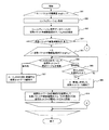
図8Aは、本発明の第1実施形態の仮想ネットワーク構成計算部37によって実行される仮想ネットワーク特定処理のフローチャートである。
FIG. 8A is a flowchart of the virtual network specifying process executed by the virtual network
仮想ネットワーク構成計算部37は、コンフィグレーション管理データベース42aに格納されたすべてのパケット中継装置10の構成情報に対して、ステップ302〜315の処理を実行する(301)。
The virtual network
まず、仮想ネットワーク構成計算部37は、コンフィグレーション管理データベース42aに格納された一のパケット中継装置10の構成情報を取得する(302)。そして、仮想ネットワーク構成計算部37は、取得した構成情報から仮想パケット中継装置識別子及びVLAN IDを抽出する(303)。
First, the virtual network
次に、仮想ネットワーク構成計算部37は、ステップ303の処理で仮想パケット中継装置識別子が抽出されたか否かを判定する(304)。
Next, the virtual network
これは、図1に示すパケット中継装置10dのように、仮想パケット中継装置20を生成せずに、パケット中継装置10d自体が仮想ネットワークを構成する場合もあり、当該パケット中継装置10dの場合、仮想ネットワーク識別子と仮想パケット中継装置識別子とを対応付けることができないため、仮想ネットワーク識別子と仮想パケット中継装置識別子とを対応付けるステップ306〜310の処理と異なる処理(ステップ311〜315の処理)が必要となるからである。
The
ステップ303の処理で仮想パケット中継装置識別子が抽出されたとステップ304の処理で判定された場合、仮想ネットワーク構成計算部37は、ステップ303の処理で抽出された仮想パケット中継装置識別子から処理対象となる一の仮想パケット中継装置識別子を選択し、ステップ303〜310の処理を実行する(305)。なお、仮想ネットワーク構成計算部37は、ステップ303の処理で抽出されたすべての仮想パケット中継装置識別子に対してステップ306〜310の処理を実行する。
When it is determined in
まず、仮想ネットワーク構成計算部37は、処理対象の仮想パケット中継装置識別子に対応付けられたVLAN IDから処理対象となる一のVLAN IDを選択し、選択した処理対象のVLAN IDが仮想ネットワーク構成テーブル43aに登録されているか否かを判定する(306)。
First, the virtual network
ステップ306の処理で、処理対象のVLAN IDが仮想ネットワーク構成テーブル43aに登録されていると判定された場合、仮想ネットワーク構成計算部37は、仮想ネットワーク構成テーブル43aを参照し、処理対象のVLAN IDと同一のVLAN IDに対応付けられた仮想ネットワーク識別子を、処理対象の仮想パケット中継装置識別子の仮想パケット中継装置20によって構成される仮想ネットワークの仮想ネットワーク識別子に設定する(307)。
When it is determined in the process of
そして、仮想ネットワーク構成計算部37は、ステップ307の処理で設定された仮想ネットワーク識別子と、処理対象の仮想パケット中継装置識別子及び当該処理対象の仮想パケット中継装置識別子に対応付けられたすべてのVLAN IDとを対応付けて仮想ネットワーク構成テーブル43aに新たなエントリとして登録する(310)。
Then, the virtual network
一方、ステップ306の処理で、処理対象のVLAN IDが仮想ネットワーク構成テーブル43aに登録されていないと判定された場合、仮想ネットワーク構成計算部37は、処理対象の仮想パケット中継装置識別子に対応付けられたすべてのVLAN IDを選択したか否かを判定する(308)。
On the other hand, if it is determined in
ステップ308の処理で、処理対象の仮想パケット中継装置識別子に対応付けられたすべてのVLAN IDを選択したと判定された場合、仮想ネットワーク構成計算部37は、新たな仮想ネットワーク識別子を生成し、生成した仮想ネットワーク識別子を、処理対象の仮想パケット中継装置識別子の仮想パケット中継装置20によって構成される仮想ネットワークの仮想ネットワーク識別子に設定する(309)。
If it is determined in
これは、処理対象の仮想パケット中継装置識別子によって識別される仮想パケット中継装置20に設定されたすべてのVLANと同じVLANがネットワークに存在しないため、当該仮想パケット中継装置20によって構成される仮想ネットワークは未登録の仮想ネットワークであり、当該仮想ネットワークに対して仮想ネットワーク識別子を新たに生成する必要があるためである。
This is because the same VLAN as all VLANs set in the virtual
そして、仮想ネットワーク構成計算部37は、ステップ310の処理に進み、ステップ309の処理で設定された仮想ネットワーク識別子と、処理対象の仮想パケット中継装置識別子及び当該処理対象の仮想パケット中継装置識別子に対応付けられたすべてのVLAN IDとを対応付けて仮想ネットワーク構成テーブル43aに新たなエントリとして登録する。
Then, the virtual network
一方、ステップ308の処理で、処理対象の仮想パケット中継装置識別子に対応付けられたすべてのVLAN IDを選択していないと判定された場合、処理対象の仮想パケット中継装置識別子に対応付けられたVLAN IDから他の一のVLAN IDを処理対象のVLAN IDとして選択し、ステップ306の処理に戻る。
On the other hand, if it is determined in
ステップ303の処理で抽出されたすべての仮想パケット中継装置識別子に対してステップ306〜310の処理が実行されていない場合、仮想ネットワーク構成計算部37は、ステップ306の処理に戻り、次のパケット中継装置識別子と当該パケット中継装置識別子に対応付けられるVLAN IDを選択し、ステップ306〜310の処理を実行する。
When the processes of
一方、ステップ303の処理で抽出されたすべての仮想パケット中継装置識別子に対してステップ306〜310の処理が実行された場合であって、かつ、コンフィグレーション管理データベース42aに格納されたすべてのパケット中継装置10の構成情報に対してステップ302〜315の処理が実行された場合、仮想ネットワーク特定処理を終了する。
On the other hand, all the packet relays stored in the
また、ステップ303の処理で抽出されたすべての仮想パケット中継装置識別子に対してステップ306〜310の処理を実行された場合であって、かつ、コンフィグレーション管理データベース42aに格納されたすべてのパケット中継装置10の構成情報に対してステップ302〜315の処理が実行されていない場合、仮想ネットワーク構成計算部37は、ステップ302の処理に戻り、コンフィグレーション管理データベース42aに格納されたパケット中継装置10の構成情報から次のパケット中継装置10の構成情報を取得し、ステップ303〜ステップ315の処理を実行する。
In addition, all the packet relays stored in the
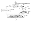
次に、ステップ303の処理で仮想パケット中継装置識別子が抽出されなかったとステップ304の処理で判定された場合の仮想ネットワーク特定処理を、図8Bを用いて説明する。図8Bは、本発明の第1実施形態の仮想ネットワーク特定処理のフローチャートである。
Next, the virtual network specifying process when it is determined in
まず、仮想ネットワーク構成計算部37は、ステップ303の処理で抽出されたVLAN IDから処理対象となる一のVLAN IDを選択し、選択した処理対象のVLAN IDが仮想ネットワーク構成テーブル43aに登録されているか否かを判定する(311)。
First, the virtual network
ステップ311の処理で、処理対象のVLAN IDが仮想ネットワーク構成テーブル43aに登録されていると判定された場合、仮想ネットワーク構成計算部37は、仮想ネットワーク構成テーブル43aを参照し、処理対象のVLAN IDと同一のVLAN IDに対応付けられた仮想ネットワーク識別子を、処理対象のVLAN IDが設定されるパケット中継装置10によって構成される仮想ネットワークの仮想ネットワーク識別子に設定する(312)。
When it is determined in
そして、仮想ネットワーク構成計算部37は、ステップ312の処理で設定された仮想ネットワーク識別子と、ステップ302の処理で構成情報を取得したパケット中継装置10のパケット中継装置識別子及び当該パケット中継装置識別子に対応付けられたすべてのVLAN IDとを対応付けて仮想ネットワーク構成テーブル43aに新たなエントリとして登録する(315)。
Then, the virtual network
一方、ステップ311の処理で、処理対象のVLAN IDが仮想ネットワーク構成テーブル43aに登録されていないと判定された場合、仮想ネットワーク構成計算部37は、ステップ303の処理で抽出されたすべてのVLAN IDを選択したか否かを判定する(313)。
On the other hand, if it is determined in
ステップ303の処理で抽出されたすべてのVLAN IDを選択したとステップ313の処理で判定された場合、仮想ネットワーク構成計算部37は、新たな仮想ネットワーク識別子を生成し、生成した仮想ネットワーク識別子を、処理対象のVLAN IDが設定されるパケット中継装置10によって構成される仮想ネットワークの仮想ネットワーク識別子に設定する(314)。
When it is determined in
これは、ステップ302の処理で構成情報を取得したパケット中継装置10に設定されたすべてのVLANと同じVLANがネットワークに存在しないため、当該パケット中継装置10によって構成される仮想ネットワークは未登録の仮想ネットワークであり、当該仮想ネットワークに対して仮想ネットワーク識別子を新たに生成する必要があるためである。
This is because the same VLAN as all the VLANs set in the
そして、仮想ネットワーク構成計算部37は、ステップ315の処理に進み、ステップ314の処理で設定された仮想ネットワーク識別子と、ステップ302の処理で構成情報を取得したパケット中継装置10のパケット中継装置識別子及び当該パケット中継装置識別子に対応付けられたすべてのVLAN IDとを対応付けて仮想ネットワーク構成テーブル43aに新たなエントリとして登録する。
Then, the virtual network
一方、ステップ303の処理で抽出されたすべてのVLAN IDを選択していないと、ステップ313の処理で判定された場合、ステップ303の処理で抽出されたVLAN IDから他の一のVLAN IDを処理対象のVLAN IDとして選択し、ステップ311の処理に戻る。
On the other hand, if it is determined in
次に、図8A及び図8Bを用いて説明した仮想ネットワーク特定処理を、図4に示すコンフィグレーション管理データベース42a及び図5に示す仮想ネットワーク構成テーブル43aを例にして、より具体的に説明する。
Next, the virtual network specifying process described with reference to FIGS. 8A and 8B will be described more specifically with the
まず、ステップ302の処理で、仮想ネットワーク構成計算部37は、コンフィグレーション管理データベース42aからパケット中継装置10aの構成情報を取得したとする。そして、仮想ネットワーク構成計算部37は、ステップ303の処理で、取得した構成情報から、「仮想パケット中継装置識別子:100、VLAN ID:10」、「100、100」、「200、20」、及び「200、200」を抽出する。
First, it is assumed that the virtual network
ステップ303の処理で仮想パケット中継装置識別子「100」及び「200」が抽出されているので、ステップ304の処理では、仮想パケット中継装置識別子が抽出されていると判定され、ステップ305の処理に進む。
Since the virtual packet relay device identifiers “100” and “200” are extracted in the process of
ステップ305の処理では、処理対象の仮想パケット中継装置識別子として仮想パケット中継装置識別子「100」が選択されるものとする。
In the processing of
次に、ステップ306の処理では、処理対象のVLAN IDとしてVLAN ID「10」が選択され、VLAN ID「10」が仮想ネットワーク構成テーブル43aに登録されているか否かが判定される。
Next, in the processing of
ここで、仮想ネットワーク構成テーブル43aには何も登録されていないものとする。このため、ステップ306の処理では、VLAN ID「10」が仮想ネットワーク構成テーブル43aに登録されていないと判定され、ステップ308の処理に進み、処理対象の仮想パケット中継装置識別子「100」に対応付けられたすべてのVLAN ID「10」及び「100」が選択されたか否かが判定される。
Here, it is assumed that nothing is registered in the virtual network configuration table 43a. Therefore, in the process of
VLAN ID「100」は未だ処理対象のVLAN IDとして選択されていないので、VLAN ID「100」を処理対象のVLAN IDとして選択し、ステップ306の処理に戻る。 Since the VLAN ID “100” has not yet been selected as the processing target VLAN ID, the VLAN ID “100” is selected as the processing target VLAN ID, and the processing returns to step 306.
ステップ306の処理では、VLAN ID「100」が仮想ネットワーク構成テーブル43aに登録されていないと判定され、ステップ308の処理に進む。
In the process of
ステップ308の処理では、処理対象の仮想パケット中継装置識別子「100」に対応付けられたすべてのVLAN ID「10」及び「100」が選択されたと判定され、ステップ309の処理に進む。
In the process of
ステップ309の処理で仮想ネットワーク識別子「50a」が新たに生成され、ステップ310の処理では、仮想ネットワーク識別子「50a」と、パケット中継装置識別子「100」と、VLAN ID「10」及び「100」とが対応付けられ、仮想ネットワーク構成テーブル43aに登録される(図5に示すエントリ501及び502参照)。
In
次に、仮想パケット中継装置識別子「200」についても、ステップ305〜310の処理を実行する。仮想パケット中継装置識別子「200」のVLAN ID「20」及び「200」は仮想ネットワーク構成テーブル43aに登録されていないので、ステップ309の処理で、仮想ネットワーク識別子「50b」が新たに生成される。そして、ステップ310の処理で、仮想ネットワーク識別子「50b」と、パケット中継装置識別子「200」と、VLAN ID「20」及び「200」とが対応付けられ、仮想ネットワーク構成テーブル43aに登録される(図5に示すエントリ505及び506参照)。
Next, the processing of
次に、ステップ302の処理で、仮想ネットワーク構成計算部37は、コンフィグレーション管理データベース42aからパケット中継装置10bの構成情報を取得したとする。そして、仮想ネットワーク構成計算部37は、ステップ303の処理で、取得した構成情報から、「仮想パケット中継装置識別子:100、VLAN ID:10」、「300、20」、及び「300、200」を抽出する。
Next, it is assumed that the virtual network
ステップ303の処理で仮想パケット中継装置識別子「100」及び「300」が抽出されているので、ステップ304の処理では、仮想パケット中継装置識別子が抽出されていると判定され、ステップ305の処理に進む。
Since the virtual packet relay device identifiers “100” and “300” are extracted in the process of
ステップ305の処理では、処理対象の仮想パケット中継装置識別子として仮想パケット中継装置識別子「100」が選択されるものとする。
In the processing of
次に、ステップ306の処理では、処理対象のVLAN IDとしてVLAN ID「10」が選択され、VLAN ID「10」が仮想ネットワーク構成テーブル43aに登録されているか否かが判定される。
Next, in the processing of
この場合、仮想ネットワーク構成テーブル43aには、エントリ501、502、505、及び506が登録されているものとする。
In this case, it is assumed that
したがって、仮想ネットワーク構成テーブル43aにVLAN ID「10」がエントリ501に登録されているので、ステップ307の処理に進み、VLAN ID「10」に対応付けられた仮想ネットワーク識別子「50a」をパケット中継装置10bの仮想パケット中継装置「100」が属する仮想ネットワークの仮想ネットワーク識別子として取得する。そして、ステップ310の処理では、仮想ネットワーク識別子「50a」と、仮想パケット中継装置識別子「100」及びVLAN ID「10」とが対応付けられ、仮想ネットワーク構成テーブル43aに登録される(図5に示すエントリ503参照)。
Therefore, since the VLAN ID “10” is registered in the
仮想ネットワーク構成計算部37は、仮想パケット中継装置識別子「300」についても、ステップ305〜310の処理を実行する。仮想パケット中継装置識別子「300」のVLAN ID「20」及び「200」は仮想ネットワーク構成テーブル43aのエントリ505及び506に登録されているので、ステップ307の処理で、仮想パケット中継装置識別子「300」とVLAN ID「20」、「200」とが対応付けられ、仮想ネットワーク構成テーブル43aに登録される(図5に示すエントリ507及び508参照)。
The virtual network
次に、ステップ302の処理で、仮想ネットワーク構成計算部37は、コンフィグレーション管理データベース42aからパケット中継装置10dの構成情報を取得したとする。そして、仮想ネットワーク構成計算部37は、ステップ303の処理で、取得した構成情報から、「VLAN ID:200」を抽出する。
Next, in the process of
ステップ303の処理で仮想パケット中継装置識別子が抽出されていないので、ステップ304の処理では、仮想パケット中継装置識別子が抽出されていないと判定され、ステップ311の処理に進む。
Since the virtual packet relay device identifier has not been extracted in the process of
ステップ311の処理では、処理対象のVLAN IDとしてVLAN ID「200」が選択され、VLAN ID「200」が仮想ネットワーク構成テーブル43aに登録されているか否かが判定される。
In the processing of
この場合、仮想ネットワーク構成テーブル43aには、エントリ506、及び508が登録されているので、ステップ312の処理に進み、VLAN ID「200」に対応付けられた仮想ネットワーク識別子「50b」をパケット中継装置10dが属する仮想ネットワークの仮想ネットワーク識別子として取得する。そして、ステップ315の処理では、仮想ネットワーク識別子「50b」と、パケット中継装置識別子「10d」及びVLAN ID「200」とが対応付けられ、仮想ネットワーク構成テーブル43aに登録される(図5に示すエントリ509参照)。
In this case, since
以上の処理を管理計算機30が管理するすべてのパケット中継装置10に実行することによって、図5に示す仮想ネットワーク構成テーブル43aが生成される。
The virtual network configuration table 43a shown in FIG. 5 is generated by executing the above processing on all the
図8A及び図8Bに示す仮想ネットワーク特定処理を実行することによって、異なる仮想パケット中継装置識別子が設定される仮想パケット中継装置20によって仮想ネットワークが構築された場合であっても、同じ仮想ネットワークを構成する仮想パケット中継装置20の仮想パケット中継装置識別子は同じ仮想ネットワーク識別子と対応付けられる。これによって、仮想ネットワーク識別子を参照することによって、同じ仮想ネットワークを構成する仮想パケット中継装置を特定できる。
By executing the virtual network specifying process shown in FIGS. 8A and 8B, the same virtual network is configured even when the virtual network is constructed by the virtual
また、仮想ネットワーク識別子に対応付けられたVLAN IDが設定されたパケット中継装置10を接続して表示装置44に描画することによって、ネットワーク管理者は、各仮想ネットワークの構成を、同じ仮想ネットワークを構成するパケット中継装置10の接続関係を容易に確認できる。
Further, by connecting the
次に、管理計算機30がパケット中継装置10に構成情報を設定する構成情報設定処理について、図9を用いて説明する。
Next, configuration information setting processing in which the
図9は、本発明の第1実施形態の構成情報設定処理のシーケンス図である。 FIG. 9 is a sequence diagram of the configuration information setting process according to the first embodiment of this invention.
ネットワーク管理者又はコンフィグレーション生成部39はパケット中継装置10の設定要求をパケット中継装置設定部38に入力する(S202)。
The network administrator or the
コンフィグレーション生成部39は、例えば、ネットワーク管理者から図6に示すネットワーク構成表示画面800を介してパケット中継装置10の追加指示を受け付けた場合、仮想ネットワーク構成テーブル43aを参照し、新たに追加されるパケット中継装置10に設定される仮想パケット中継装置識別子及びVLAN IDを決定し(S201)、決定した仮想パケット中継装置識別子及びVLAN IDを新たに追加されるパケット中継装置10の構成情報に設定する設定要求をパケット中継装置設定部38に入力する。
For example, when receiving an instruction to add the
なお、S201の処理は、図10で詳細を説明する。 Details of the processing of S201 will be described with reference to FIG.
パケット中継装置設定部38は、設定要求が入力されると、構成情報を設定するパケット中継装置10のパケット中継装置管理部22にセッション確立要求を送信する(S203)。
When the setting request is input, the packet relay
パケット中継装置管理部22は、図7に示すS102の処理と同じく、セッションを確立できるか否かを判定し、セッションを確立できると判定された場合、セッション確立応答を管理計算機のパケット中継装置設定部38に送信する(S204)。なお、図7に示すS102の処理のように、これ以降に管理計算機30と当該パケット中継装置10との間で通信されるパケットにはセッション識別子が付与される。
The packet relay
管理計算機30のパケット中継装置設定部38は、パケット中継装置10からセッション確立応答を受信した場合、セッションを確立したパケット中継装置10のコンフィグレーション23に対して排他的設定権を設定する要求であるロック取得要求をパケット中継装置10のパケット中継装置10のパケット中継装置管理部22に送信する(S205)。コンフィグレーション23に対して排他的設定権(ロック)が設定された場合、排他的設定権が設定された管理計算機30以外の装置は当該コンフィグレーション23を設定できず、排他的設定権が設定された管理計算機30のみが当該コンフィグレーション23を設定できる。
When receiving a session establishment response from the
パケット中継装置管理部22は、コンフィグレーション23に対して排他的設定権が設定できるか否かを判定し、コンフィグレーション23に対して排他的設定権が設定できると判定された場合、ロック取得応答を管理計算機30のパケット中継装置設定部38に送信する(S206)。
The packet
例えば、コンフィグレーション23に対してすでに排他的設定権が設定されている場合、コンフィグレーション23に対して排他的設定権が設定できないと判定し、コンフィグレーション23に対して排他的設定権が設定されていない場合、コンフィグレーション23に対して排他的設定権が設定できると判定する。
For example, if the exclusive setting right is already set for the
パケット中継装置設定部38は、パケット中継装置10からロック取得応答を受信した場合、S202の処理で入力された設定要求をパケット中継装置10のパケット中継装置管理部22に送信する(S207)。
When receiving a lock acquisition response from the
パケット中継装置管理部22は、管理計算機30から設定要求を受信した場合、受信した設定要求をコンフィグレーション管理部21に入力する(S208)。
When receiving the setting request from the
コンフィグレーション管理部21は、設定要求が入力された場合、入力された設定要求に基づいて、コンフィグレーション23を更新する(S209)。そして、コンフィグレーション管理部21は、更新した構成情報を含む設定応答をパケット中継装置管理部22に入力する(S210)。
When a setting request is input, the
パケット中継装置管理部22は、設定応答が入力された場合、入力された応答を、管理計算機30のパケット中継装置設定部38に送信する(S211)。
When the setting response is input, the packet relay
管理計算機30のパケット中継装置設定部38は、設定応答を受信した場合、受信した設定応答に含まれる更新した構成情報に基づいて、コンフィグレーション管理データベース42aを更新する(S212)。
When receiving the setting response, the packet relay
また、パケット中継装置設定部38は、パケット中継装置10のコンフィグレーション23に対して設定された排他的設定権を解除する要求であるロック開放要求をパケット中継装置10のパケット中継装置管理部22に送信する(S213)。
Further, the packet relay
パケット中継管理部22は、コンフィグレーション23に対して設定された排他的設定権を解除できるか否かを判定し、排他的設定権を解除できると判定された場合、排他的設定権を解除し、ロック開放応答をパケット中継装置設定部38に送信する(S214)。
The packet
パケット中継装置設定部38は、パケット中継装置10からロック開放応答を受信した場合、セッションを切断する要求であるセッション切断要求を、パケット中継装置10のパケット中継装置管理部22に送信する(S215)。
When receiving the unlock release response from the
パケット中継装置管理部22は、管理計算機30からセッション切断要求を受信した場合、セッションを切断し、セッション切断応答を管理計算機30のパケット中継装置設定部38に送信する(S216)。
When receiving the session disconnection request from the
この後、コンフィグレーション生成部38は、コンフィグレーション管理データベース42aを参照し、パケット中継装置10の構成した構成情報に基づいて、仮想ネットワーク構成テーブル43aを更新する(S217)。
Thereafter, the
具体的には、パケット中継装置識別子10cに、仮想パケット中継装置識別子200とVLAN識別子100とを設定した場合、S212の処理で、設定後のパケット中継装置10cに仮想パケット中継装置識別子200とVLAN識別子100とを設定したことをコンフィグレーション管理データベース42aに登録し、S217の処理で、パケット中継装置10cの仮想パケット中継装置200に関するエントリを、仮想ネットワーク構成テーブル43aに新たなエントリとして登録する。
Specifically, when the virtual packet
次に、図9に示すS201の処理、つまり、新たに追加するパケット中継装置10に設定する構成情報(仮想パケット中継装置識別子及びVLAN ID)を決定する構成情報決定処理について図10を用いて説明する。
Next, the processing of S201 shown in FIG. 9, that is, the configuration information determination processing for determining configuration information (virtual packet relay device identifier and VLAN ID) to be set in the newly added
図10は、本発明の第1実施形態の構成情報決定処理のフローチャートである。 FIG. 10 is a flowchart of the configuration information determination process according to the first embodiment of this invention.
構成情報決定処理は、管理計算機30のコンフィグレーション生成部39によって実行される。
The configuration information determination process is executed by the
まず、コンフィグレーション生成部39は、ネットワーク管理者からのネットワーク構成表示画面800(図6参照)を介して入力されたパケット中継装置Xの追加指示を受け付ける(601)。追加指示は、パケット中継装置Xを追加する仮想ネットワーク識別子、新たに追加されるパケット中継装置Xの接続先となる接続先パケット中継装置のパケット中継装置識別子(接続先パケット中継装置識別子)、及び、接続先パケット中継装置に備わるパケット送受信ポート14のうち新たにパケット中継装置Xが接続される接続先パケット送受信ポートの識別子(接続先パケット送受信ポート識別子)を含む。
First, the
当該仮想ネットワーク識別子は、図6に示すネットワーク構成表示画面800において追加ボタン831が操作された場合、仮想ネットワーク一覧表示領域810にて選択されていた仮想ネットワークの識別子である。
The virtual network identifier is the identifier of the virtual network selected in the virtual network
また、接続先パケット中継装置識別子は、追加ボタン831が操作された場合にネットワークトポロジ表示領域820にて選択されていたパケット中継装置10のパケット中継装置識別子である。
The connection destination packet relay device identifier is the packet relay device identifier of the
また、接続先パケット送受信ポート識別子は、追加ボタン831が操作された場合にネットワークトポロジ表示領域820にてパケット送受信ポート14のパケット送受信ポート識別子である。
The connection destination packet transmission / reception port identifier is the packet transmission / reception port identifier of the packet transmission / reception port 14 in the network
次に、コンフィグレーション生成部39は、受け付けた追加指示を参照し、パケット中継装置Xを追加する仮想ネットワーク識別子を特定する(602)。
Next, the
そして、コンフィグレーション生成部39は、仮想ネットワーク構成テーブル43aのエントリのうち、仮想ネットワーク識別子431に登録された仮想ネットワーク識別子が、ステップ602の処理で特定された仮想パケット中継装置識別子と一致するエントリを特定し、特定したエントリの仮想パケット中継装置識別子433に登録された仮想パケット中継装置識別子を取得する(603)。
Then, the
そして、コンフィグレーション生成部39は、ステップ603の処理で取得した仮想パケット中継装置識別子を配列に格納する(604)。
Then, the
次に、コンフィグレーション生成部39は、ステップ604の処理で配列に格納された一の仮想パケット中継装置識別子を処理対象の仮想パケット中継装置識別子として選択し、ステップ604の処理で配列に格納されたすべての仮想パケット中継装置識別子に対して、ステップ606〜608の処理を実行する(605)。
Next, the
まず、コンフィグレーション生成部39は、コンフィグレーション管理データベース42aを参照し、新たに追加されるパケット中継装置Xの構成情報を取得する。そして、コンフィグレーション生成部39は、取得したパケット中継装置Xの構成情報を参照し、処理対象の仮想パケット中継装置識別子がパケット中継装置Xに設定できるか否かを判定する(606)。
First, the
具体的には、コンフィグレーション生成部39は、処理対象の仮想パケット中継装置がパケット中継装置Xに生成された仮想パケット中継装置識別子にすでに使用されているか否か、及び処理対象の仮想パケット中継装置識別子は、パケット中継装置Xが設定可能な仮想パケット中継装置識別子であるか否かを判定する。
Specifically, the
なお、パケット中継装置Xが設定可能な仮想パケット中継装置識別子は、パケット中継装置Xの型番によって特定される。 The virtual packet relay device identifier that can be set by the packet relay device X is specified by the model number of the packet relay device X.
ステップ606の処理で、処理対象の仮想パケット中継装置識別子がパケット中継装置Xに設定できると判定された場合、コンフィグレーション生成部39は、処理対象の仮想パケット中継装置識別子を、パケット中継装置Xが新たに生成する仮想パケット中継装置に割り当てることを決定する(607)。
When it is determined in
一方、ステップ606の処理で、処理対象の仮想パケット中継装置識別子がパケット中継装置Xに設定できないと判定された場合、コンフィグレーション生成部39は、新たな仮想パケット中継装置識別子を生成し、生成した仮想パケット中継装置識別子を、パケット中継装置Xが新たに生成する仮想パケット中継装置に割り当てることを決定する(608)。
On the other hand, when it is determined in
ステップ604の処理で配列に格納されたすべての仮想パケット中継装置識別子に対して、ステップ606〜608の処理が実行されると、コンフィグレーション生成部39は、コンフィグレーション管理データベース42aを参照し、追加指示に含まれる接続先パケット中継装置識別子によって識別される接続先パケット中継装置Yの構成情報を取得する。そして、コンフィグレーション生成部39は、取得した接続先パケット中継装置Yの構成情報を参照し、接続先パケット中継装置Yに備わるパケット送受信ポート14のうち、新たに追加される接続パケット中継装置Yが接続される接続先パケット送受信ポートに設定されるVLAN IDを取得し、パケット中継装置Xに設定するVLAN IDを取得したVLAN IDに決定する(609)。
When the processing of
ここで、コンフィグレーション管理データベース42aでは、VLAN IDと当該VLAN IDが設定されたパケット中継装置10に備わるパケット送受信ポート14のポート識別子とが対応付けられているものとする。このため、コンフィグレーション生成部39は、取得した接続先パケット中継装置Yの構成情報のうち、追加指示に含まれる接続先パケット送受信ポート識別子と一致するパケット送受信ポート識別子に対応するVLAN IDを取得する。
Here, in the
次に、コンフィグレーション生成部39は、ステップ607又は608の処理で決定された仮想パケット中継装置識別子、及び、ステップ609の処理で決定されたVLAN IDをパケット中継装置Xの構成情報に設定する設定要求を、パケット中継装置設定部38に入力し(610)、構成情報決定処理を終了する。
Next, the
以上によって、仮想ネットワークに新たにパケット中継装置10を追加する場合、当該パケット中継装置10に生成される仮想パケット中継装置20の仮想パケット中継装置識別子及びVLAN IDを自動的に設定するので、ネットワーク管理者は新たに追加されるパケット中継装置10に生成される仮想パケット中継装置20の仮想パケット中継装置識別子及びVLAN IDを意識することなく、仮想ネットワークを構築できる。
As described above, when a new
次に、構成情報決定処理を、仮想ネットワーク50aにパケット中継装置10cが追加される場合を例に説明する。
Next, the configuration information determination process will be described by taking as an example a case where the
ステップ602の処理で、コンフィグレーション生成部39は、パケット中継装置10cが追加される仮想ネットワーク識別子が「50a」であると特定する。
In
次に、ステップ603の処理で、コンフィグレーション生成部39は、仮想ネットワーク構成テーブル43aを参照し、仮想ネットワーク識別子「50a」が登録されたエントリ(図5に示す501〜503)を特定し、特定したエントリの仮想パケット中継装置識別子「100」を取得する。そして、ステップ604の処理で、仮想パケット中継装置識別子「100」が配列に格納される。
Next, in the process of
ステップ606の処理では、コンフィグレーション生成部39は、仮想パケット中継装置識別子「100」が仮想パケット中継装置20cに設定できるか否かを判定する。ここでは、仮想パケット中継装置識別子「100」はパケット中継装置10cに設定できないと判定されるものとし、ステップ608の処理に進む。
In
ステップ608の処理では、コンフィグレーション生成部39は、新たな仮想パケット中継装置識別子「200」を生成し、仮想パケット中継装置識別子「200」をパケット中継装置10cに生成される仮想パケット中継装置に割り当てる仮想パケット中継装置識別子とする。
In the processing of
そして、ステップ609の処理で、コンフィグレーション生成部39は、パケット中継装置10cの接続先パケット中継装置10aに備わるパケット送受信ポート14のうちパケット中継装置10cに接続される接続先パケット送受信ポートに対応付けられたVLAN ID「100」を取得する。
In
ステップ610の処理では、コンフィグレーション生成部39は、パケット中継装置10cに仮想パケット中継装置識別子「200」及びVLAN ID「100」を設定する設定要求をパケット中継装置設定部38に入力する。
In
次に、ネットワーク管理者からの設定要求をコンフィグレーション生成部39が受け付けた場合に実行される誤設定検出処理について図11を用いて説明する。
Next, an erroneous setting detection process executed when the
図11は、本発明の第1実施形態の誤設定検出処理のフローチャートである。 FIG. 11 is a flowchart of erroneous setting detection processing according to the first embodiment of this invention.
ネットワーク管理者は、図示しない設定画面を介して、所定の仮想ネットワークを構成する仮想パケット中継装置20にVLAN IDを設定する設定要求を管理計算機30に入力できる。
The network administrator can input a setting request for setting a VLAN ID to the virtual
ここで、設定対象となる仮想ネットワーク以外の仮想ネットワークを構成する仮想パケット中継装置20に当該設定するVLAN IDが設定されている場合には、当該VLAN IDを設定対象となる仮想パケット中継装置20に設定できない。これは、異なる仮想ネットワークに属し、通信できない仮想パケット中継装置20に同じVLAN IDを付与することになり、当該設定はネットワーク管理者の誤設定である。
Here, when the VLAN ID to be set is set in the virtual
図1を例に説明すると、例えば、仮想ネットワーク50aを構成するパケット中継装置10a(仮想パケット中継装置20a、仮想パケット中継装置識別子100)にVLAN300が設定されている状態で、ネットワーク管理者が仮想ネットワーク50bを構成するパケット中継装置10b(仮想パケット中継装置20d、仮想パケット中継装置識別子300)にVLAN300を設定する要求をしたとする。この場合、VLAN300を介して、本来異なる仮想ネットワークに属する仮想パケット中継装置20aと仮想パケット中継装置20dとの間で情報が通信される可能性がある。つまり、本来分離しているはずの仮想ネットワーク50aの情報と仮想ネットワーク50bの情報とが、混在してしまう可能性がある。
Referring to FIG. 1 as an example, for example, in a state where the
誤設定検出処理は、上述したネットワーク管理者の誤設定を検出するための処理である。 The erroneous setting detection process is a process for detecting the erroneous setting of the network administrator described above.
まず、コンフィグレーション生成部39は、ネットワーク管理者からの設定要求を受け付ける(701)。当該設定要求は、設定対象となる仮想パケット中継装置20の仮想パケット中継装置識別子(設定対象仮想パケット中継装置識別子)、設定対象となる仮想パケット中継装置20が生成されたパケット中継装置10のパケット中継装置識別子(設定対象パケット中継装置識別子)、及び当該仮想パケット中継装置に設定されるVLAN ID(設定VLAN ID)を含む。
First, the
次に、コンフィグレーション生成部39は、仮想ネットワーク構成テーブル42を参照し、設定対象となる仮想パケット中継装置20が構成する仮想ネットワークの仮想ネットワーク識別子を特定し、設定要求に含まれる設定VLAN IDを特定する(702)。
Next, the
次に、コンフィグレーション生成部39は、仮想ネットワーク構成テーブル43aを参照し、設定対象仮想ネットワーク識別子に対応付けられたパケット中継装置識別子を検索する(703)。
Next, the
コンフィグレーション生成部39は、ステップ703の処理で検索されたパケット中継装置識別子から、設定対象パケット中継装置以外のパケット中継装置識別子を配列に格納する(704)。
The
次に、コンフィグレーション生成部39は、配列に格納されたパケット中継装置識別子から処理対象となる一のパケット中継装置識別子を選択し、ステップ706〜709の処理を実行する(705)。なお、いずれかのパケット中継装置識別子について設定中止と判定されるか、配列に格納されたすべてのパケット中継装置識別子について設定継続と判定されるまで、ステップ706〜709の処理は繰り返し実行される。
Next, the
コンフィグレーション生成部39は、仮想ネットワーク構成テーブル43aを参照し、処理対象のパケット中継装置識別子にステップ702の処理で特定された仮想ネットワーク識別子以外の仮想ネットワーク識別子が対応付けられているか否かを判定する(706)。
The
ステップ706の処理で、ステップ702の処理で特定された仮想ネットワーク識別子以外の仮想ネットワーク識別子(他の仮想ネットワーク識別子)が処理対象のパケット中継装置識別子に対応付けられてないと判定された場合、コンフィグレーション生成部39は、設定継続と判定し(707)、配列に格納されたすべてのパケット中継装置識別子にステップ706〜708の処理が実行されていない場合、他のパケット中継装置識別子を処理対象のパケット中継装置識別子として選択し、ステップ706の処理を実行する。また、配列に格納されたすべてのパケット中継装置識別子に設定継続と判定された場合、コンフィグレーション生成部39は、設定VLAN IDを設定対象の仮想パケット中継装置20が生成されたパケット中継装置10の構成情報に設定する設定要求を、パケット中継装置設定部38に入力し(710)、誤設定検出処理を終了する。
If it is determined in
一方、ステップ706の処理で、他の仮想ネットワーク識別子が処理対象のパケット中継装置識別子に対応付けられていると判定された場合、コンフィグレーション生成部39は、仮想ネットワーク構成テーブル43aを参照し、処理対象のパケット中継装置識別子によって識別されるパケット中継装置10に生成された仮想パケット中継装置(処理対象の仮想パケット中継装置)20のうち、他の仮想ネットワーク識別子によって識別される仮想ネットワーク(他の仮想ネットワーク)を構成する仮想パケット中継装置20に設定VLAN IDが設定されているか否かを判定する(708)。
On the other hand, when it is determined in
具体的には、コンフィグレーション生成部39は、仮想ネットワーク構成テーブル43aに登録されたエントリのうち、仮想ネットワーク識別子431に他の仮想ネットワーク識別子が登録され、かつ、パケット中継装置識別子432に処理対象のパケット中継装置識別子が登録されたエントリを特定する。そして、コンフィグレーション生成部39は、特定したエントリのVLAN ID434に設定VLAN IDが登録されているか否かを判定する。
Specifically, the
ステップ708の処理で、処理対象の仮想パケット中継装置20のうち他の仮想ネットワークを構成する仮想パケット中継装置20に設定VLAN IDが設定されていると判定された場合、コンフィグレーション生成部39は、設定対象の仮想ネットワーク以外の仮想ネットワークに設定VLAN IDが設定されているので、当該設定VLAN IDの設定は誤設定であり、設定中止と判定し(709)、誤設定検出処理を終了する。
When it is determined in
一方、ステップ708の処理で、処理対象の仮想パケット中継装置20のうち他の仮想ネットワークを構成する仮想パケット中継装置20に設定VLAN IDが設定されていないと判定された場合、コンフィグレーション生成部39は、ステップ707の処理に進み、設定継続と判定する。
On the other hand, if it is determined in
以上によって、仮想パケット中継装置にVLAN IDの誤設定を防止することができる。 As described above, erroneous setting of the VLAN ID in the virtual packet relay device can be prevented.
次に、図1に示すパケット中継装置10bに生成された仮想パケット中継装置20d(仮想パケット中継装置識別子300)にVLAN ID100を設定する場合を例に誤設定検出処理を説明する。
Next, an erroneous setting detection process will be described by taking as an example the case where the
ステップ702の処理で、コンフィグレーション生成部39は、仮想パケット中継装置20dが構成する仮想ネットワークは仮想ネットワーク50bであり、設定VLAN IDが「100」であることを特定する。
In
ステップ703の処理で、コンフィグレーション生成部39は、設定対象仮想ネットワーク識別子「50b」に対応付けられたパケット中継装置識別子「10a」、「10b」、「10d」を検索する。
In
ステップ704の処理で、コンフィグレーション生成部39は、ステップ703の処理で検索されたパケット中継装置識別子「10a」、「10b」、「10d」から設定対象パケット中継装置識別子「10b」以外のパケット中継装置識別子「10a」、「10d」を配列に格納する。
In the process of
ステップ705の処理で、コンフィグレーション生成部39は、処理対象のパケット中継装置識別子「10a」を選択する。
In
ステップ706の処理では、コンフィグレーション生成部39は、パケット中継装置識別子「10a」に他の仮想ネットワーク識別子50aが対応付けられていると判定し、ステップ708の処理に進む。
In the process of
ステップ708の処理では、コンフィグレーション生成部39は、パケット中継装置10aに生成される仮想パケット中継装置20a(仮想パケット中継装置識別子100)には、設定VLAN ID「100」が登録されていると判定し、ステップ709の処理に進み、設定中止と判定し、誤設定検出処理を終了する。
In
仮想ネットワーク50bを構成する仮想パケット中継装置20d(仮想パケット中継装置識別子300)にVLAN ID100が設定されれば、当該VLAN100を介して仮想ネットワーク50aと仮想ネットワーク50bとの情報が混在してしまう可能性があるので、ステップ709の処理で設定中止と判定し、ステップ710の処理を実行しないようにしている。
If the
(第2実施形態)
第2実施形態について図12〜図21を用いて説明する。
(Second Embodiment)
A second embodiment will be described with reference to FIGS.
第1実施形態では、一の仮想ネットワークは、設定される仮想的なネットワーク(第2ネットワーク)がVLANである場合について説明したが、第2実施形態では、仮想パケット中継装置20とパケット送受信ポート14とが対応付けられることによって、第2ネットワークが構築される場合について説明する。
In the first embodiment, a case has been described in which one virtual network is a virtual network (second network) to be set, but in the second embodiment, the virtual
図12は、本発明の第2実施形態のネットワーク管理システムのネットワーク構成図である。なお、本実施形態のネットワーク管理システムは、図1に示す第1実施形態のネットワーク管理システムと異なる箇所のみを説明する。 FIG. 12 is a network configuration diagram of the network management system according to the second embodiment of this invention. Note that the network management system according to the present embodiment will be described only in parts different from the network management system according to the first embodiment shown in FIG.
ネットワーク管理システムは、パケット中継装置10e〜10h及び管理計算機30を備える。
The network management system includes
パケット中継装置10e上で、仮想パケット中継装置20f及び20gが動作し、パケット中継装置10f上で、仮想パケット中継装置20h及び20iが動作し、パケット中継装置10g上で、仮想パケット中継装置20jが動作している。
The virtual packet relay devices 20f and 20g operate on the
仮想パケット中継装置20fとパケット中継装置10eに備わるパケット送受信ポート「10」及び「11」とが対応付けられ、仮想パケット中継装置20gとパケット中継装置10eに備わるパケット送受信ポート「20」及び「21」とが対応付けられる。
The packet transmission / reception ports “10” and “11” provided in the virtual packet relay device 20f and the
また、仮想パケット中継装置20gとパケット中継装置10gに備わるパケット送受信ポート「10」とが対応付けられる。
Further, the virtual packet relay device 20g and the packet transmission / reception port “10” provided in the
さらに、仮想パケット中継装置20hとパケット中継装置10fに備わるパケット送受信ポート「10」とが対応付けられ、仮想パケット中継装置20iとパケット中継装置10fに備わるパケット送受信ポート「20」及び「21」とが対応付けられる。
Further, the virtual packet relay device 20h and the packet transmission / reception port “10” provided in the
なお、パケット送受信ポート14の直後にかっこ書きした数字は、パケット送受信ポート14の識別子であるパケット送受信ポート識別子である。パケット送受信ポート識別子は、当該パケット送受信ポート14を備えるパケット中継装置10内で一意な識別子である。
The number in parentheses immediately after the packet transmission / reception port 14 is a packet transmission / reception port identifier which is an identifier of the packet transmission / reception port 14. The packet transmission / reception port identifier is an identifier unique within the
また、仮想パケット中継装置20に対応付けられたパケット送受信ポート14を、仮想パケット中継装置20に属するパケット送受信ポート14という。
The packet transmission / reception port 14 associated with the virtual
仮想パケット中継装置20に属するパケット送受信ポート14を他の仮想パケット中継装置20に属するパケット送受信ポート14に接続することによって、仮想パケット中継装置20同士を連結する。これによって、一つの物理ネットワーク上に複数の仮想的なネットワーク(第1ネットワーク)を構築できる。
By connecting the packet transmission / reception port 14 belonging to the virtual
図12では、仮想パケット中継装置20f、仮想パケット中継装置20h、仮想パケット中継装置20jが一つの仮想ネットワーク(以降、仮想ネットワークC)を構成する。また、仮想パケット中継装置20g、仮想パケット中継装置20i、パケット中継装置10hが、一つの仮想ネットワーク(以降、仮想ネットワークD)を構成する。以上により、一つの物理ネットワーク上に、二つの仮想ネットワーク(第1ネットワーク)が構築される。
In FIG. 12, the virtual packet relay device 20f, the virtual packet relay device 20h, and the virtual packet relay device 20j constitute one virtual network (hereinafter referred to as virtual network C). The virtual packet relay device 20g, the virtual packet relay device 20i, and the
仮想ネットワークCでは、仮想パケット中継装置20fに属するパケット送受信ポート「11」と仮想パケット中継装置20jに属するパケット送受信ポート「10」とが接続され、仮想パケット中継装置20fに属するパケット送受信ポート「10」と仮想パケット中継装置20hに属するパケット送受信ポート「10」とが接続される。このため、仮想ネットワークCは、仮想パケット中継装置20fに属するパケット送受信ポート「11」と仮想パケット中継装置20jに属するパケット送受信ポート「10」との間のネットワーク(第2ネットワーク)、及び、仮想パケット中継装置20fに属するパケット送受信ポート「10」と仮想パケット中継装置20hに属するパケット送受信ポート「10」との間のネットワークに分割される。 In the virtual network C, the packet transmission / reception port “11” belonging to the virtual packet relay device 20f and the packet transmission / reception port “10” belonging to the virtual packet relay device 20j are connected, and the packet transmission / reception port “10” belonging to the virtual packet relay device 20f. Are connected to the packet transmission / reception port “10” belonging to the virtual packet relay device 20h. Therefore, the virtual network C includes a network (second network) between the packet transmission / reception port “11” belonging to the virtual packet relay device 20f and the packet transmission / reception port “10” belonging to the virtual packet relay device 20j, and the virtual packet. The network is divided between the packet transmission / reception port “10” belonging to the relay device 20f and the packet transmission / reception port “10” belonging to the virtual packet relay device 20h.
また、仮想ネットワークDでは、仮想パケット中継装置20gに属するパケット送受信ポート「20」と仮想パケット中継装置20iに属するパケット送受信ポート「20」とが接続され、仮想パケット中継装置20iに属するパケット送受信ポート「21」とパケット中継装置10hに属するパケット送受信ポート「20」とが接続される。このため、仮想ネットワークDは、仮想パケット中継装置20gに属するパケット送受信ポート「20」と仮想パケット中継装置20iに属するパケット送受信ポート「20」との間のネットワーク、及び、仮想パケット中継装置20iに属するパケット送受信ポート「21」とパケット中継装置10hに属するパケット送受信ポート「20」との間のネットワークに分割される。
In the virtual network D, the packet transmission / reception port “20” belonging to the virtual packet relay device 20g and the packet transmission / reception port “20” belonging to the virtual packet relay device 20i are connected, and the packet transmission / reception port “20” belonging to the virtual packet relay device 20i is connected. 21 ”and the packet transmission / reception port“ 20 ”belonging to the
図13は、本発明の第2実施形態のパケット中継装置10の構成を示すブロック図である。なお、図13では、図2に示す第1実施形態のパケット中継装置10と同じ構成は同じ符号を付与し、説明を省略する。
FIG. 13 is a block diagram illustrating a configuration of the
本実施形態のパケット中継装置10は、第1実施形態のパケット中継装置10の構成に隣接装置情報管理部24及び隣接装置情報25を追加したものである。
The
隣接装置情報管理部24は、隣接装置情報25を管理する。隣接装置情報25は、自身に備わるパケット送受信ポート14の接続先のパケット中継装置10(隣接パケット中継装置)の識別子である隣接パケット中継装置識別子、及び、接続先のパケット送受信ポート14の識別子であるパケット送受信ポート識別子の関係を保持する。
The adjacent device
なお、隣接装置情報25は、パケット中継装置10が隣接パケット中継装置とパケット中継装置識別子及びパケット送受信ポート識別子を含む情報を交換することによって収集される。
The
図14は、本発明の第2実施形態の管理計算機30の構成を示すブロック図である。なお、図14では、図3に示す第1実施形態の管理計算機30と同じ構成は同じ符号を付与し、説明を省略する。
FIG. 14 is a block diagram illustrating a configuration of the
本実施形態の管理計算機30は、第1実施形態の管理計算機30の構成に隣接装置情報データベース47を追加したものである。
The
隣接装置情報データベース47には、管理計算機30によって取得された各パケット中継装置10の隣接装置情報25が格納される。隣接装置情報データベース47の詳細は図16で詳細を説明する。
The adjacent
図15は、本発明の第2実施形態のコンフィグレーション管理データベース42bの説明図である。
FIG. 15 is an explanatory diagram of the
コンフィグレーション管理データベース42bは、図4に示すコンフィグレーション管理データベース42aのVLAN ID423の代わりにパケット送受信ポート424を含む。
The
パケット送受信ポート424には、仮想パケット中継装置20に属するパケット送受信ポート14のパケット送受信ポート識別子が登録される。
In the packet transmission /
図16は、本発明の第2実施形態の隣接装置情報データベース47の説明図である。
FIG. 16 is an explanatory diagram of the adjacent
隣接装置情報データベース47は、パケット中継装置471、パケット送受信ポート472、隣接パケット中継装置473、及びパケット送受信ポート474を含む。
The adjacent
パケット中継装置471には、隣接装置情報25を取得したパケット中継装置10の識別子が登録される。パケット送受信ポート372には、隣接装置情報25を取得したパケット中継装置10のパケット送受信ポート14の識別子が登録される。
In the
隣接パケット中継装置473には、隣接装置情報25を取得したパケット中継装置10のパケット送受信ポート14に接続される隣接パケット中継装置の識別子が登録される。パケット送受信ポート474には、隣接パケット中継装置に備わるパケット送受信ポート14のうち、隣接装置情報25を取得したパケット中継装置10のパケット送受信ポート14に接続されるパケット送受信ポート14の識別子が登録される。
In the adjacent
図17は、本発明の第2実施形態の仮想ネットワーク構成テーブル43bの説明図である。 FIG. 17 is an explanatory diagram of the virtual network configuration table 43b according to the second embodiment of this invention.
仮想ネットワーク構成テーブル43bは、図5に示す第1実施形態の仮想ネットワーク構成テーブル43baのVLAN ID434の代わりにパケット送受信ポート435を含む。
The virtual network configuration table 43b includes a packet transmission /
パケット送受信ポート435には、仮想ネットワーク識別子に対応するパケット送受信ポート識別子が登録される。
A packet transmission / reception port identifier corresponding to the virtual network identifier is registered in the packet transmission /
図18は、本発明の第2実施形態の管理計算機30の表示装置44に表示されるネットワーク構成表示画面800の説明図である。
FIG. 18 is an explanatory diagram of a network
本実施形態のネットワーク構成表示画面800は、図6に示すネットワーク構成表示画面800と、ネットワークトポロジ表示領域820でVLAN IDを表示せず、パケット送受信ポート識別子を表示する点で異なる。
The network
図15では、仮想ネットワーク一覧表示領域810で仮想ネットワーク50dが選択されるので、ネットワーク構成表示画面800では、仮想ネットワーク50dに属するパケット中継装置10e、10f及び10hが表示され、パケット中継装置10eのパケット送受信ポート「20」とパケット中継装置10fのパケット送受信ポート「20」とが接続され、パケット中継装置10fのパケット送受信ポート「21」とパケット中継装置10hのパケット送受信ポート「20」とが接続されることが表示される。
In FIG. 15, since the
ネットワーク管理者によって選択された仮想ネットワークに属するパケット中継装置10の特定処理、及び、パケット中継装置10間の接続関係の特定処理について説明する。
A description will be given of the specifying process of the
まず、仮想ネットワーク構成計算部37が、図17に示す仮想ネットワーク構成テーブル43bを参照し、仮想ネットワーク識別子431に選択された仮想ネットワークの識別子が登録されるエントリを取得する。そして、仮想ネットワーク構成計算部37は、取得したエントリのパケット中継装置識別子432に登録されたパケット中継装置識別子を当該仮想ネットワークに属するパケット中継装置10の識別子として特定する。
First, the virtual network
さらに、仮想ネットワーク構成計算部37は、取得したエントリのパケット送受信ポート435に同じVLAN IDが登録されているパケット中継装置10間が接続されていると特定する。
Furthermore, the virtual network
このため、仮想ネットワークが異なる識別子を有する仮想パケット中継装置によって構成されている場合であっても、仮想ネットワーク識別子は表示装置44には表示されないので、ネットワーク管理者は識別子を意識することなく、各仮想ネットワークの構成を確認できる。
For this reason, even if the virtual network is configured by virtual packet relay devices having different identifiers, the virtual network identifier is not displayed on the
図19は、本発明の第2実施形態の管理計算機30がパケット中継装置10から隣接装置情報25を取得する隣接装置情報取得処理のシーケンス図である。
FIG. 19 is a sequence diagram of adjacent device information acquisition processing in which the
隣接装置情報取得処理は、図7に示す第1実施形態の構成情報取得処理と、管理計算機30が隣接装置情報25をパケット中継装置10から取得し、取得した隣接装置情報25を隣接装置情報データベース47に格納する点で異なるが、他の点では同じ処理である。
The adjacent device information acquisition processing is the same as the configuration information acquisition processing of the first embodiment shown in FIG. 7, the
管理計算機30のパケット中継装置参照部36は、すべてのパケット中継装置10のパケット中継装置管理部22にセッション確立要求を送信する(S301)。S301の処理は、図7に示すS101の処理に対応する。
The packet relay
パケット中継装置管理部22は、セッションを確立できる場合、セッション識別子を含むセッション確立応答を、管理計算機30のパケット中継装置参照部36に送信する(S302)。S302の処理は、図7に示すS102の処理に対応する。
When the session can be established, the packet relay
管理計算機30のパケット中継装置参照部36は、パケット中継装置10からセッション確立応答を受信した場合、当該パケット中継装置10の隣接装置情報25を取得する要求である隣接装置情報参照要求を、当該パケット中継装置10に送信する(S303)。S303の処理は、図7に示すS103の処理に対応する。
When receiving a session establishment response from the
パケット中継装置10のパケット中継装置管理部22は、管理計算機30から隣接装置情報参照要求を受信した場合、受信した隣接装置情報参照要求をコンフィグレーション管理部21に渡す(S304)。S304の処理は、図7に示すS104の処理に対応する。
When receiving the adjacent device information reference request from the
コンフィグレーション管理部21は、パケット中継装置管理部22から隣接装置情報参照要求を渡された場合、隣接装置情報25を参照し(S305)、隣接装置情報25を取得し、取得した隣接装置情報25を含めた隣接装置情報参照応答を、パケット中継装置管理部22に渡す(S306)。パケット中継装置管理部22は、渡された隣接装置情報参照応答を管理計算機30のパケット中継装置参照部36に送信する(S307)。S305〜S307の処理は、図7に示すS105〜S107の処理に対応する。
When the
パケット中継装置管理部22は、パケット中継装置10から隣接装置情報参照応答を受信した場合、受信した隣接装置情報参照応答に含まれる隣接装置情報25を、隣接装置情報データベース47に登録し(S308)、隣接装置情報参照応答を送信したパケット中継装置10のパケット中継装置管理部22に、セッションを切断する要求であるセッション切断要求を送信する(S309)。S308及びS309の処理は、図7に示すS108及びS109の処理に対応する。
When receiving the adjacent device information reference response from the
パケット中継装置管理部22は、管理計算機30からセッション切断要求を受信した場合、セッションを切断し、セッション切断応答を、管理計算機30のパケット中継装置参照部36に送信する(S310)。S310の処理は、図7に示すS110の処理に対応する。
When receiving the session disconnection request from the
以上、管理計算機30がパケット中継装置10の隣接装置情報25を取得する手順について説明した。
The procedure for the
この後、仮想ネットワーク構成計算部37は、隣接装置情報データベース47を参照し(S311)、仮想パケット中継装置20が構成する仮想ネットワークを特定し、当該仮想パケット中継装置20の仮想パケット中継装置識別子と特定した仮想ネットワークの仮想ネットワーク識別子とを対応付け、仮想ネットワーク構成テーブル43bに登録する(S312)。
Thereafter, the virtual network
なお、S311及びS312の処理は、仮想ネットワーク特定処理といい、図20A及び図20Bで詳細を説明する。 Note that the processing of S311 and S312 is called virtual network identification processing, and will be described in detail with reference to FIGS. 20A and 20B.
図20Aは、本発明の第2実施形態の仮想ネットワーク構成計算部37によって実行される仮想ネットワーク特定処理のフローチャートである。図20Aでは、図8Aに示す仮想ネットワーク特定処理と同じ処理は同じ符号を付与し、説明を省略する。
FIG. 20A is a flowchart of the virtual network specifying process executed by the virtual network
仮想ネットワーク構成計算部37は、ステップ302の処理で、コンフィグレーション管理データベース42bに格納された一のパケット中継装置10の構成情報を取得した後、仮想ネットワーク構成計算部37は、取得した構成情報から仮想パケット中継装置識別子及びパケット送受信ポート識別子を抽出する(1101)。
After the virtual network
ステップ305の処理で、処理対象となる一の仮想パケット中継装置識別子を選択した後、仮想ネットワーク構成計算部37は、処理対象の仮想パケット中継装置識別子によって識別される仮想パケット中継装置20に備わるパケット送受信ポート14のパケット送受信ポート識別子の中から、処理対象となる一のパケット送受信ポート識別子を選択する。そして、仮想ネットワーク構成計算部37は、隣接装置情報データベース47を参照し、処理対象のパケット送受信ポート識別子によって識別されるパケット送受信ポート14に接続される隣接パケット中継装置Yの隣接パケット中継装置識別子、及び隣接パケット送受信ポート識別子を特定する(1102)。
After selecting one virtual packet relay device identifier to be processed in the process of
そして、仮想ネットワーク構成計算部37は、ステップ1102の処理で特定した隣接パケット中継装置識別子、及び隣接パケット送受信ポート識別子が仮想ネットワーク構成テーブル43bに登録されているか否かを判定する(1103)。
Then, the virtual network
ステップ1103の処理で、隣接パケット中継装置識別子、及び隣接パケット送受信ポート識別子が仮想ネットワーク構成テーブル43bに登録されていると判定された場合、仮想ネットワーク構成計算部37は、仮想ネットワーク構成テーブル43bを参照し、隣接パケット中継装置識別子、及び隣接パケット送受信ポート識別子に対応付けられた仮想ネットワーク識別子を、処理対象の仮想パケット中継装置識別子の仮想パケット中継装置20によって構成される仮想ネットワークの仮想ネットワーク識別子に設定する(1104)。
When it is determined in
そして、仮想ネットワーク構成計算部37は、ステップ1104の処理で設定された仮想ネットワーク識別子と、処理対象の仮想パケット中継装置識別子及び当該処理対象の仮想パケット中継装置識別子に対応付けられたすべてのパケット送受信ポート識別子とを対応付けて仮想ネットワーク構成テーブル43bに新たなエントリとして登録する(1106)。
Then, the virtual network
一方、ステップ1103の処理で、隣接パケット中継装置識別子、及び隣接パケット送受信ポート識別子が仮想ネットワーク構成テーブル43bに登録されていないと判定された場合、仮想ネットワーク構成計算部37は、処理対象の仮想パケット中継装置識別子によって識別される仮想パケット中継装置20に備わるすべてのパケット送受信ポート14のパケット送受信ポート識別子を処理対象のパケット送受信ポート識別子として選択したか否かを判定する(1105)。
On the other hand, when it is determined in
ステップ1105の処理で、処理対象の仮想パケット中継装置識別子によって識別される仮想パケット中継装置20に備わるすべてのパケット送受信ポート14のパケット送受信ポート識別子を処理対象のパケット送受信ポート識別子として選択したと判定された場合、ステップ309の処理に進み、仮想ネットワーク構成計算部37は、新たな仮想ネットワーク識別子を生成し、生成した仮想ネットワーク識別子を、処理対象の仮想パケット中継装置識別子の仮想パケット中継装置20によって構成される仮想ネットワークの仮想ネットワーク識別子に設定する。
In
一方、ステップ1105の処理で、処理対象の仮想パケット中継装置識別子によって識別される仮想パケット中継装置20に備わるすべてのパケット送受信ポート14のパケット送受信ポート識別子を処理対象のパケット送受信ポート識別子として選択していないと判定された場合、ステップ1103の処理に戻り、処理対象のパケット送受信ポート識別子を新たに選択する。
On the other hand, in
次に、ステップ1101の処理で仮想パケット中継装置識別子が抽出されなかったとステップ304の処理で判定された場合の仮想ネットワーク特定処理を、図20Bを用いて説明する。図20Bは、本発明の第2実施形態の仮想ネットワーク特定処理のフローチャートである。
Next, the virtual network specifying process in the case where it is determined in
まず、仮想ネットワーク構成計算部37は、処理対象となるパケット中継装置10に備わるパケット送受信ポート14のパケット送受信ポート識別子の中から、処理対象となる一のパケット送受信ポート識別子を選択する。そして、仮想ネットワーク構成計算部37は、隣接装置情報データベース47を参照し、処理対象のパケット送受信ポート識別子によって識別されるパケット送受信ポート14に接続される隣接パケット中継装置Yの隣接パケット中継装置識別子、及び隣接パケット送受信ポート識別子を特定する(1107)。
First, the virtual network
そして、仮想ネットワーク構成計算部37は、ステップ1107の処理で特定した隣接パケット中継装置識別子、及び隣接パケット送受信ポート識別子が仮想ネットワーク構成テーブル43bに登録されているか否かを判定する(1108)。
Then, the virtual network
ステップ1108の処理で、隣接パケット中継装置識別子、及び隣接パケット送受信ポート識別子が仮想ネットワーク構成テーブル43bに登録されていると判定された場合、仮想ネットワーク構成計算部37は、仮想ネットワーク構成テーブル43bを参照し、隣接パケット中継装置識別子、及び隣接パケット送受信ポート識別子に対応付けられた仮想ネットワーク識別子を、処理対象のパケット中継装置10によって構成される仮想ネットワークの仮想ネットワーク識別子に設定する(1109)。
If it is determined in
そして、仮想ネットワーク構成計算部37は、ステップ1109の処理で設定された仮想ネットワーク識別子と、処理対象のパケット中継装置識別子及び当該処理対象のパケット中継装置識別子に対応付けられたすべてのパケット送受信ポート識別子とを対応付けて仮想ネットワーク構成テーブル43bに新たなエントリとして登録する(1111)。
Then, the virtual network
一方、ステップ1108の処理で、隣接パケット中継装置識別子、及び隣接パケット送受信ポート識別子が仮想ネットワーク構成テーブル43bに登録されていないと判定された場合、仮想ネットワーク構成計算部37は、処理対象のパケット中継装置識別子によって識別されるパケット中継装置10に備わるすべてのパケット送受信ポート14のパケット送受信ポート識別子を処理対象のパケット送受信ポート識別子として選択したか否かを判定する(1110)。
On the other hand, when it is determined in
ステップ1110の処理で、処理対象のパケット中継装置識別子によって識別されるパケット中継装置10に備わるすべてのパケット送受信ポート14のパケット送受信ポート識別子を処理対象のパケット送受信ポート識別子として選択したと判定された場合、ステップ314の処理に進み、仮想ネットワーク構成計算部37は、新たな仮想ネットワーク識別子を生成し、生成した仮想ネットワーク識別子を、処理対象のパケット中継装置識別子のパケット中継装置10によって構成される仮想ネットワークの仮想ネットワーク識別子に設定する。
When it is determined in
一方、ステップ1110の処理で、処理対象のパケット中継装置識別子によって識別されるパケット中継装置10に備わるすべてのパケット送受信ポート14のパケット送受信ポート識別子を処理対象のパケット送受信ポート識別子として選択していないと判定された場合、ステップ1103の処理に戻り、処理対象のパケット送受信ポート識別子を新たに選択する。
On the other hand, if the packet transmission / reception port identifiers of all the packet transmission / reception ports 14 included in the
次に、図20A及び図20Bを用いて説明した仮想ネットワーク特定処理を、図15に示すコンフィグレーション管理データベース42b、図16に示す隣接装置情報データベース47、及び図17に示す仮想ネットワーク構成テーブル43bを例にして、より具体的に説明する。
Next, the virtual network specifying process described with reference to FIGS. 20A and 20B is performed using the
まず、ステップ302の処理で、仮想ネットワーク構成計算部37は、コンフィグレーション管理データベース42bからパケット中継装置10eの構成情報を取得したとする。そして、仮想ネットワーク構成計算部37は、ステップ1101の処理で、取得した構成情報から、「仮想パケット中継装置識別子:100、パケット送受信ポート識別子:10」、「100、11」、「200、20」、及び「200、21」を抽出する。
First, it is assumed that the virtual network
ステップ1101の処理で仮想パケット中継装置識別子「100」及び「200」が抽出されているので、ステップ304の処理では、仮想パケット中継装置識別子が抽出されていると判定され、ステップ305の処理に進む。
Since the virtual packet relay device identifiers “100” and “200” are extracted in the process of
ステップ305の処理では、処理対象の仮想パケット中継装置識別子として仮想パケット中継装置識別子「100」が選択されるものとする。
In the processing of
次に、ステップ1105の処理では、処理対象のパケット送受信ポート識別子としてパケット送受信ポート識別子「10」が選択される。ステップ1102の処理では、パケット送受信ポート識別子「10」の隣接パケット中継装置識別子「10f」及び隣接パケット送受信ポート識別子「10」が特定される。
Next, in
そして、ステップ1103の処理で、隣接パケット中継装置識別子「10f」及び隣接パケット送受信ポート識別子「10」が仮想ネットワーク構成テーブル43bに登録されているか否かが判定される。
In
ここでは、隣接パケット中継装置識別子「10f」及び隣接パケット送受信ポート識別子「10」が仮想ネットワーク構成テーブル43bに登録されているものとする(図17に示すエントリ1003参照)。当該エントリ1003の仮想ネットワーク識別子は「50c」である。
Here, it is assumed that the adjacent packet relay device identifier “10f” and the adjacent packet transmission / reception port identifier “10” are registered in the virtual network configuration table 43b (see
そして、ステップ1104の処理に進み、仮想ネットワーク識別子「50c」をパケット中継装置10eの仮想パケット中継装置「100」が属する仮想ネットワークの仮想ネットワーク識別子として取得する。そして、ステップ1110の処理では、仮想ネットワーク識別子「50c」と、仮想パケット中継装置識別子「100」及びパケット送受信ポート識別子「10」及び「11」とが対応付けられ、仮想ネットワーク構成テーブル43bに登録される(図17に示すエントリ1001及び1002参照)。
Then, the process proceeds to step 1104, and the virtual network identifier “50c” is acquired as the virtual network identifier of the virtual network to which the virtual packet relay device “100” of the
仮想ネットワーク構成計算部37は、パケット中継装置10eの仮想パケット中継装置識別子「200」についても、上述した処理を実行する。この場合、図16に示す隣接装置情報データベース47を参照すると、パケット中継装置10eのパケット送受信ポート「20」には隣接パケット中継装置10f及び隣接パケット送受信ポート「20」が接続される。そして、図17に示す仮想ネットワーク構成テーブル43bには、隣接パケット中継装置10f及び隣接パケット送受信ポート「20」には、仮想ネットワーク識別子「50d」が対応付けられているので、仮想ネットワーク識別子「50d」と、仮想パケット中継装置識別子「200」及びパケット送受信ポート識別子「20」及び「21」とが対応付けられ、仮想ネットワーク構成テーブル43bに登録される(図17に示すエントリ1005及び1006参照)。
The virtual network
次に、ステップ302の処理で、仮想ネットワーク構成計算部37は、コンフィグレーション管理データベース42bからパケット中継装置10hの構成情報を取得したとする。パケット中継装置10hの構成情報(パケット送受信ポート識別子「20」)には、仮想パケット中継装置識別子が登録されていないので、ステップ1107の処理に進む。
Next, in the process of
ステップ1107の処理では、仮想ネットワーク構成計算部37は、隣接装置情報データベース47を参照すると、パケット中継装置10hのパケット送受信ポート「20」には隣接パケット中継装置10fの隣接パケット送受信ポート「21」が接続されていると特定する。
In the processing of
次に、仮想ネットワーク構成計算部37は、ステップ1108の処理で、隣接パケット中継装置識別子10fの隣接パケット送受信ポート識別子「21」が仮想ネットワーク構成テーブル43bに登録されているか否かを判定する。
Next, the virtual network
ここでは、隣接パケット中継装置識別子10fの隣接パケット送受信ポート識別子「21」が仮想ネットワーク構成テーブル43bに登録されているものとする(図17に示すエントリ1008)。
Here, it is assumed that the adjacent packet transmission / reception port identifier “21” of the adjacent packet
そして、ステップ1109の処理で、図17に示すエントリ1008の仮想ネットワーク識別子「50d」をパケット中継装置10hが属する仮想ネットワークの仮想ネットワーク識別子として取得する。
In
次に、ステップ1111の処理で、仮想ネットワーク識別子「50d」とパケット中継装置10hのパケット送受信ポート識別子「20」とを対応付けて、仮想ネットワーク構成テーブル43bに登録する(1009)。
Next, in step 1111, the virtual network identifier “50d” and the packet transmission / reception port identifier “20” of the
以上の処理を管理計算機30が管理するパケット中継装置10の数だけ繰り返し実行することによって、図17に示す仮想ネットワーク構成テーブル43bが生成される。
The virtual network configuration table 43b shown in FIG. 17 is generated by repeatedly executing the above processing for the number of
図21は、本発明の第2実施形態の構成情報決定処理のフローチャートである。図21では、図10に示す第1実施形態の構成情報決定処理と同じ処理は同じ符号を付与し、説明を省略する。 FIG. 21 is a flowchart of configuration information determination processing according to the second embodiment of this invention. In FIG. 21, the same process as the configuration information determination process of the first embodiment shown in FIG.
本実施形態の構成情報決定処理では、仮想パケット中継識別子を決定するまでの処理(ステップ601〜608の処理)は、図10に示す第1実施形態の構成情報決定処理と同じである。なお、第2実施形態での追加指示には、新たに追加されるパケット中継装置Xの接続先パケット中継装置に接続されるパケット送受信ポート14(接続元パケット送受信ポート)の識別子(接続元パケット送受信ポート識別子)も含まれる。
In the configuration information determination process of the present embodiment, the processes until the virtual packet relay identifier is determined (the processes in
なお、接続元パケット送受信ポート識別子は、追加ボタン831が操作された場合にネットワークトポロジ表示領域820にて選択されていた新たに追加されるパケット中継装置10のパケット送受信ポート14のパケット送受信ポート識別子である。
The connection source packet transmission / reception port identifier is a packet transmission / reception port identifier of the packet transmission / reception port 14 of the newly added
ステップ604の処理で配列に格納されたすべての仮想パケット中継識別子に対して、ステップ606〜608の処理を実行した後、コンフィグレーション生成部39は、追加指示に含まれる接続元パケット送受信ポート識別子を取得し(1201)、ステップ607又は608の処理でパケット中継装置Xが新たに生成する仮想パケット中継装置に割り当てると決定された仮想パケット中継装置識別子と、取得した接続元パケット送受信ポート識別子とを対応付ける。
After executing the processing of
次に、コンフィグレーション生成部39は、ステップ607又は608の処理で決定された仮想パケット中継装置識別子、及び、ステップ1201の処理で取得した接続元パケット送受信ポート識別子をパケット中継装置Xの構成情報に設定する設定要求を、パケット中継装置設定部38に入力し(1202)、構成情報決定処理を終了する。
Next, the
以上によって、仮想ネットワークに新たなパケット中継装置10を追加する場合であっても、管理計算機30が、ネットワーク管理者に代わって、仮想パケット中継識別子の設定をするので、ネットワーク管理者は仮想パケット中継装置識別子を意識することなく、仮想ネットワークを構築することが可能となる。
As described above, even when a new
なお、今回開示された実施の形態はすべての点で例示であって制限的なものではないと考えられるべきである。本発明の範囲は上記した意味ではなく、特許請求の範囲によって示され、特許請求の範囲と均等の意味および範囲内でのすべての変更が含まれることが意図される。 The embodiment disclosed this time should be considered as illustrative in all points and not restrictive. The scope of the present invention is defined by the terms of the claims, rather than the meaning described above, and is intended to include any modifications within the scope and meaning equivalent to the terms of the claims.
11 ネットワークインタフェースモジュール
12 スイッチングモジュール
13 制御モジュール
14 パケット送受信ポート
15 コントローラ
16 メモリ
17 CPU
18 ソフトウェア処理部
19 パケット送受信部
20 仮想パケット中継装置
21 コンフィグレーション管理部
22 パケット中継装置管理部
23 コンフィグレーション
24 隣接装置情報管理部
25 隣接装置情報
30 管理計算機
31 ネットワークインタフェース
32 ハードディスク
33 ソフトウェア処理部
34 パケット送受信部
35 ネットワーク管理部
36 パケット中継装置参照部
37 仮想ネットワーク構成計算部
38 パケット中継装置設定部
39 コンフィグレーション生成部
40 インターネット
41 ユーザインタフェース部
42a、42b コンフィグレーション管理データベース
43a、43b 仮想ネットワーク構成テーブル
44 表示装置
45 キーボード
46 マウス
47 隣接装置情報データベース
11
DESCRIPTION OF
Claims (12)
前記パケット中継装置は、少なくとも一つの仮想パケット中継装置を生成可能であって、
前記複数のパケット中継装置に生成された仮想パケット中継装置は、複数の仮想的な第1ネットワークを提供し、
前記仮想パケット中継装置には、当該仮想パケット中継装置が生成されたパケット中継装置内で一意な仮想パケット中継装置識別子が付与され、
前記各第1ネットワークは、少なくとも一つ以上の仮想的な第2ネットワークに分割可能であって、
前記パケット中継装置は、自身に付与された仮想パケット中継装置識別子及び前記第2ネットワークの識別子である第2ネットワーク識別子を構成情報として管理し、
前記ネットワーク管理システムは、
前記パケット中継装置から構成情報を取得し、前記取得した構成情報を構成情報管理テーブルに格納する構成情報取得部と、
前記構成情報取得部が前記パケット中継装置から構成情報を取得した場合、前記取得した構成情報に含まれる仮想パケット中継装置識別子が属する第1ネットワークを特定し、前記取得した構成情報と前記特定した第1ネットワークの識別子である第1ネットワーク識別子とを対応付けて第1ネットワーク構成テーブルに登録する第1ネットワーク特定部と、
所定の第1ネットワークの構成を表示する表示要求を受け付けた場合、前記第1ネットワーク構成テーブルを参照し、前記所定の第1ネットワークの構成を前記表示装置に表示するネットワーク構成表示部と、を備え、
前記第1ネットワーク特定部は、
前記構成情報取得部が前記パケット中継装置から構成情報を取得した場合、前記取得した構成情報から仮想パケット中継装置識別子、及び第2ネットワーク識別子を抽出し、
前記抽出した第2ネットワーク識別子に対応する前記第2ネットワーク識別子が付与された仮想パケット中継装置の仮想パケット中継装置識別子が前記第1ネットワーク構成テーブルに登録されているか否かを判定し、
前記抽出した第2ネットワーク識別子に対応する前記第2ネットワーク識別子が付与された仮想パケット中継装置の仮想パケット中継装置識別子が前記第1ネットワーク構成テーブルに登録されていないと判定された場合、新たな第1ネットワーク識別子を生成し、前記生成した第1ネットワーク識別子と前記取得した構成情報とを対応付けて前記第1ネットワーク構成テーブルに登録し、
前記抽出した第2ネットワーク識別子に対応する前記第2ネットワーク識別子が付与された仮想パケット中継装置の仮想パケット中継装置識別子が前記第1ネットワーク構成テーブルに登録されていると判定された場合、当該仮想パケット中継装置識別子に対応付けられている前記第1ネットワーク識別子と前記取得した構成情報とを対応付けて前記第1ネットワーク構成テーブルに登録し、
前記ネットワーク構成表示部は、前記表示要求を受け付けた場合、前記第1ネットワーク構成テーブルを参照し、前記所定の第1ネットワーク識別子に対応付けられる仮想パケット中継装置識別子を特定することによって、前記所定の第1ネットワークの構成を特定し、前記特定された所定の第1ネットワークの構成を前記表示装置に表示することを特徴とするネットワーク管理システム。 A network management system comprising: a plurality of packet relay devices that constitute a network; and a display device that displays a configuration of the network, and manages the plurality of packet relay devices,
The packet relay device can generate at least one virtual packet relay device,
The virtual packet relay device generated in the plurality of packet relay devices provides a plurality of virtual first networks,
The virtual packet relay device is given a virtual packet relay device identifier that is unique within the packet relay device in which the virtual packet relay device is generated,
Each of the first networks can be divided into at least one virtual second network,
The packet relay device manages, as configuration information, a virtual packet relay device identifier assigned to itself and a second network identifier that is an identifier of the second network,
The network management system includes:
A configuration information acquisition unit that acquires configuration information from the packet relay device and stores the acquired configuration information in a configuration information management table;
When the configuration information acquisition unit acquires configuration information from the packet relay device, the configuration information acquisition unit specifies a first network to which a virtual packet relay device identifier included in the acquired configuration information belongs, and the acquired configuration information and the specified first A first network specifying unit that registers the first network identifier, which is an identifier of one network, in association with the first network configuration table;
A network configuration display unit that displays the configuration of the predetermined first network on the display device by referring to the first network configuration table when a display request for displaying the configuration of the predetermined first network is received. ,
The first network specifying unit includes:
When the configuration information acquisition unit acquires configuration information from the packet relay device, a virtual packet relay device identifier and a second network identifier are extracted from the acquired configuration information,
Determining whether the virtual packet relay device identifier of the virtual packet relay device to which the second network identifier corresponding to the extracted second network identifier is assigned is registered in the first network configuration table;
When it is determined that the virtual packet relay device identifier of the virtual packet relay device to which the second network identifier corresponding to the extracted second network identifier is assigned is not registered in the first network configuration table, a new second Generating one network identifier, registering the generated first network identifier and the acquired configuration information in association with each other in the first network configuration table;
When it is determined that the virtual packet relay device identifier of the virtual packet relay device assigned with the second network identifier corresponding to the extracted second network identifier is registered in the first network configuration table, the virtual packet Registering the first network identifier associated with the relay device identifier and the acquired configuration information in the first network configuration table in association with each other;
The network configuration display unit, when receiving the display request by the first reference to the network configuration table identifies the virtual packet relay identifier associated with the predetermined first network identifier, the predetermined A network management system characterized by specifying a configuration of the first network and displaying the specified configuration of the first network on the display device.
前記第1ネットワーク特定部は、前記抽出した第2ネットワーク識別子と同一の前記第2ネットワーク識別子を、前記抽出した第2ネットワーク識別子に対応する前記第2ネットワーク識別子として特定することを特徴とする請求項1に記載のネットワーク管理システム。 Each of the first networks can be divided into at least one virtual second network VLAN according to a VLAN identifier assigned to the virtual packet relay device as the second network identifier,
The first network specifying unit specifies the second network identifier that is the same as the extracted second network identifier as the second network identifier corresponding to the extracted second network identifier. The network management system according to 1.
前記ポートには、当該ポートを識別するためのポート識別子が前記第2ネットワーク識別子として付与され、
前記ポート同士の接続により前記ポートに対応付けられた仮想パケット中継装置同士を接続することによって、前記第1ネットワークを仮想的な第2ネットワークに分割可能であって、
前記ネットワーク管理システムは、
前記パケット中継装置の前記ポート識別子と、当該ポートに接続される隣接ポートの識別子である隣接ポート識別子と、当該隣接ポートを備える隣接パケット中継装置の識別子である隣接パケット中継装置識別子と、の関係を対応付けて隣接関係テーブルに保持し、
前記第1ネットワーク特定部は、前記隣接関係テーブルを参照して、前記抽出した第2ネットワーク識別子であるポート識別子に対応する隣接ポート識別子を特定し、前記特定した隣接ポート識別子を、前記抽出した第2ネットワーク識別子に対応する前記第2ネットワーク識別子とすることを特徴とする請求項1に記載のネットワーク管理システム。 The packet relay device includes a port connected to the other packet relay device and associated with the virtual packet relay device,
A port identifier for identifying the port is given to the port as the second network identifier,
The first network can be divided into a virtual second network by connecting virtual packet relay devices associated with the ports by connecting the ports,
The network management system includes:
A relationship between the port identifier of the packet relay device, an adjacent port identifier that is an identifier of an adjacent port connected to the port, and an adjacent packet relay device identifier that is an identifier of an adjacent packet relay device that includes the adjacent port. Keep it in the adjacency table
The first network specifying unit specifies an adjacent port identifier corresponding to a port identifier that is the extracted second network identifier with reference to the adjacent relation table, and the extracted adjacent port identifier The network management system according to claim 1, wherein the second network identifier corresponding to two network identifiers is used.
前記パケット中継装置の構成情報を設定するパケット中継装置設定部と、
所定の第1ネットワークに前記パケット中継装置を追加する設定要求を受け付けた場合、前記追加するパケット中継装置に生成される仮想パケット中継装置の仮想パケット中継装置識別子を生成する構成情報生成部と、を備え、
前記設定要求は、前記パケット中継装置を追加する第1ネットワークの第1ネットワーク識別子を含み、
前記構成情報生成部は、
前記設定要求を受け付けた場合、前記第1ネットワーク構成テーブルを参照し、前記設定要求に含まれる第1ネットワーク識別子に対応付けられた前記仮想パケット中継装置識別子を取得し、
前記構成情報管理テーブルを参照し、前記取得した仮想パケット中継装置識別子が前記追加するパケット中継装置に付与できるか否かを判定し、
前記取得した仮想パケット中継装置識別子が前記追加するパケット中継装置に付与できると判定された場合、前記取得した仮想パケット中継装置識別子を、前記追加するパケット中継装置に生成される仮想パケット中継装置に割り当てるよう決定し、
前記取得した仮想パケット中継装置識別子が前記追加するパケット中継装置に付与できないと判定された場合、前記取得した仮想パケット中継装置識別子以外の仮想パケット中継装置識別子を、前記追加するパケット中継装置に生成される仮想パケット中継装置に割り当てるよう決定し、
前記パケット中継装置設定部は、前記構成情報生成部によって決定された仮想パケット中継装置識別子を、前記追加するパケット中継装置に生成される仮想パケット中継装置に割り当てるように、前記追加するパケット中継装置の構成情報を設定することを特徴とする請求項1に記載のネットワーク管理システム。 The network management system includes:
A packet relay device setting unit for setting configuration information of the packet relay device;
A configuration information generation unit that generates a virtual packet relay device identifier of a virtual packet relay device generated in the packet relay device to be added when a setting request to add the packet relay device to a predetermined first network is received; Prepared,
The setting request includes a first network identifier of a first network to which the packet relay device is added,
The configuration information generation unit
When the setting request is accepted, the virtual packet relay device identifier associated with the first network identifier included in the setting request is obtained by referring to the first network configuration table,
Refer to the configuration information management table, determine whether the acquired virtual packet relay device identifier can be given to the packet relay device to be added,
When it is determined that the acquired virtual packet relay device identifier can be assigned to the packet relay device to be added, the acquired virtual packet relay device identifier is allocated to the virtual packet relay device generated in the packet relay device to be added. Decided to
When it is determined that the acquired virtual packet relay device identifier cannot be assigned to the packet relay device to be added, a virtual packet relay device identifier other than the acquired virtual packet relay device identifier is generated in the packet relay device to be added. To assign to the virtual packet relay device
The packet relay device setting unit assigns the virtual packet relay device identifier determined by the configuration information generation unit to the virtual packet relay device generated by the packet relay device to be added. The network management system according to claim 1, wherein configuration information is set.
前記VLAN識別子は、前記パケット中継装置に備わるポートに対応して付与され、
前記設定要求は、前記追加するパケット中継装置の接続先となる接続先ポートの接続先ポート識別子、及び、当該接続先ポートを備える接続先パケット中継装置の接続先パケット中継装置識別子を含み、
前記構成情報生成部は、
前記設定要求を受け付けた場合、前記構成情報管理テーブルを参照し、前記設定要求に含まれる接続先ポート識別子によって識別されるポートに付与されたVLAN識別子を取得し、
前記取得したVLAN識別子を、前記追加するパケット中継装置に備わるポートのうち、前記接続先ポートに接続される接続元ポートに付与するよう決定し、
前記パケット中継装置設定部は、前記構成情報生成部によって決定されたVLAN識別子を前記接続元ポートに付与するように、前記追加するパケット中継装置の構成情報を設定することを特徴とする請求項4に記載のネットワーク管理システム。 Each of the first networks can be divided into at least one virtual second network VLAN according to a VLAN identifier assigned to the virtual packet relay device as the second network identifier,
The VLAN identifier is assigned corresponding to a port provided in the packet relay device,
The setting request includes a connection destination port identifier of a connection destination port that is a connection destination of the packet relay device to be added, and a connection destination packet relay device identifier of a connection destination packet relay device including the connection destination port,
The configuration information generation unit
When accepting the setting request, refer to the configuration information management table, obtain a VLAN identifier assigned to the port identified by the connection destination port identifier included in the setting request,
Determining to give the acquired VLAN identifier to a connection source port connected to the connection destination port among the ports provided in the packet relay device to be added;
5. The packet relay device setting unit sets the configuration information of the packet relay device to be added so that the VLAN identifier determined by the configuration information generation unit is assigned to the connection source port. The network management system described in 1.
設定対象となる第1ネットワークに属する設定対象となる仮想パケット中継装置にVLAN識別子を設定するVLAN設定要求を受け付けた場合、前記設定するVLAN識別子を前記設定対象となる仮想パケット中継装置に設定するよう、前記設定対象となる仮想パケット中継装置が生成されるパケット中継装置の構成情報を設定するVLAN設定部を備え、
前記VLAN設定部は、
前記第1ネットワーク構成テーブルを参照し、前記設定対象となる第1ネットワークと異なる第1ネットワークに属する仮想パケット中継装置に前記設定するVLAN識別子と同じVLAN識別子が設定されているか否かを判定し、
前記設定対象となる第1ネットワークと異なる第1ネットワークに属する仮想パケット中継装置に前記設定するVLAN識別子と同じVLAN識別子が設定されていないと判定された場合、前記設定するVLAN識別子を前記設定対象となる仮想パケット中継装置に設定するよう、前記設定対象となる仮想パケット中継装置が生成されるパケット中継装置の構成情報を設定し、
前記設定対象となる第1ネットワークと異なる第1ネットワークに属する仮想パケット中継装置に前記設定するVLAN識別子と同じVLAN識別子が設定されていると判定された場合、前記設定対象となる仮想パケット中継装置が生成されるパケット中継装置の構成情報の設定を中止することを特徴とする請求項1に記載のネットワーク管理システム。 Each of the first networks can be divided into at least one virtual second network VLAN according to a VLAN identifier assigned to the virtual packet relay device as the second network identifier,
When a VLAN setting request for setting a VLAN identifier is received in the virtual packet relay device to be set belonging to the first network to be set, the VLAN identifier to be set is set in the virtual packet relay device to be set A VLAN setting unit for setting configuration information of a packet relay device in which the virtual packet relay device to be set is generated,
The VLAN setting unit
Referring to the first network configuration table, determining whether the same VLAN identifier as the VLAN identifier to be set is set in a virtual packet relay apparatus belonging to a first network different from the first network to be set;
When it is determined that the same VLAN identifier as the VLAN identifier to be set is not set in the virtual packet relay device belonging to the first network different from the first network to be set, the VLAN identifier to be set is set as the setting target. Set the configuration information of the packet relay device in which the virtual packet relay device to be set is generated, so that the virtual packet relay device is set,
When it is determined that the same VLAN identifier as the VLAN identifier to be set is set in the virtual packet relay device belonging to the first network different from the first network to be set, the virtual packet relay device to be set is The network management system according to claim 1, wherein the setting of the configuration information of the generated packet relay device is stopped.
前記パケット中継装置は、少なくとも一つの仮想パケット中継装置を生成可能であって、
前記複数のパケット中継装置に生成された仮想パケット中継装置は、複数の仮想的な第1ネットワークを提供し、
前記仮想パケット中継装置には、当該仮想パケット中継装置が生成されたパケット中継装置内で一意な仮想パケット中継装置識別子が付与され、
前記各第1ネットワークは、少なくとも一つ以上の仮想的な第2ネットワークに分割可能であって、
前記パケット中継装置は、自身に付与された仮想パケット中継装置識別子及び前記第2ネットワークの識別子である第2ネットワーク識別子を構成情報として管理し、
前記管理計算機は、
前記パケット中継装置から構成情報を取得し、前記取得した構成情報を構成情報管理テーブルに格納する構成情報取得部と、
前記構成情報取得部が前記パケット中継装置から構成情報を取得した場合、前記取得した構成情報に含まれる仮想パケット中継装置識別子が属する第1ネットワークを特定し、前記取得した構成情報と前記特定した第1ネットワークの識別子である第1ネットワーク識別子とを対応付けて第1ネットワーク構成テーブルに登録する第1ネットワーク特定部と、
所定の第1ネットワークの構成を表示する表示要求を受け付けた場合、前記第1ネットワーク構成テーブルを参照し、前記所定の第1ネットワークの構成を前記管理計算機に接続された表示装置に表示するための表示データを生成するネットワーク構成表示部と、を備え、
前記第1ネットワーク特定部は、
前記構成情報取得部が前記パケット中継装置から構成情報を取得した場合、前記取得した構成情報から仮想パケット中継装置識別子、及び第2ネットワーク識別子を抽出し、
前記抽出した第2ネットワーク識別子に対応する前記第2ネットワーク識別子が付与された仮想パケット中継装置の仮想パケット中継装置識別子が前記第1ネットワーク構成テーブルに登録されているか否かを判定し、
前記抽出した第2ネットワーク識別子に対応する前記第2ネットワーク識別子が付与された仮想パケット中継装置の仮想パケット中継装置識別子が前記第1ネットワーク構成テーブルに登録されていないと判定された場合、新たな第1ネットワーク識別子を生成し、前記生成した第1ネットワーク識別子と前記取得した構成情報とを対応付けて前記第1ネットワーク構成テーブルに登録し、
前記抽出した第2ネットワーク識別子に対応する前記第2ネットワーク識別子が付与された仮想パケット中継装置の仮想パケット中継装置識別子が前記第1ネットワーク構成テーブルに登録されていると判定された場合、当該仮想パケット中継装置識別子に対応付けられている前記第1ネットワーク識別子と前記取得した構成情報とを対応付けて前記第1ネットワーク構成テーブルに登録し、
前記ネットワーク構成表示部は、前記表示要求を受け付けた場合、前記第1ネットワーク構成テーブルを参照し、前記所定の第1ネットワーク識別子に対応付けられる仮想パケット中継装置識別子を特定することによって、前記所定の第1ネットワークの構成を特定し、前記特定された所定の第1ネットワークの構成を表示するための表示データを生成することを特徴とする管理計算機。 A management computer that is connected to a plurality of packet relay devices constituting a network and manages the plurality of packet relay devices,
The packet relay device can generate at least one virtual packet relay device,
The virtual packet relay device generated in the plurality of packet relay devices provides a plurality of virtual first networks,
The virtual packet relay device is given a virtual packet relay device identifier that is unique within the packet relay device in which the virtual packet relay device is generated,
Each of the first networks can be divided into at least one virtual second network,
The packet relay device manages, as configuration information, a virtual packet relay device identifier assigned to itself and a second network identifier that is an identifier of the second network,
The management computer is
A configuration information acquisition unit that acquires configuration information from the packet relay device and stores the acquired configuration information in a configuration information management table;
When the configuration information acquisition unit acquires configuration information from the packet relay device, the configuration information acquisition unit specifies a first network to which a virtual packet relay device identifier included in the acquired configuration information belongs, and the acquired configuration information and the specified first A first network specifying unit that registers the first network identifier, which is an identifier of one network, in association with the first network configuration table;
When a display request for displaying a predetermined first network configuration is received, the first network configuration table is referred to, and the predetermined first network configuration is displayed on a display device connected to the management computer. A network configuration display unit for generating display data,
The first network specifying unit includes:
When the configuration information acquisition unit acquires configuration information from the packet relay device, a virtual packet relay device identifier and a second network identifier are extracted from the acquired configuration information,
Determining whether the virtual packet relay device identifier of the virtual packet relay device to which the second network identifier corresponding to the extracted second network identifier is assigned is registered in the first network configuration table;
When it is determined that the virtual packet relay device identifier of the virtual packet relay device to which the second network identifier corresponding to the extracted second network identifier is assigned is not registered in the first network configuration table, a new second Generating one network identifier, registering the generated first network identifier and the acquired configuration information in association with each other in the first network configuration table;
When it is determined that the virtual packet relay device identifier of the virtual packet relay device assigned with the second network identifier corresponding to the extracted second network identifier is registered in the first network configuration table, the virtual packet Registering the first network identifier associated with the relay device identifier and the acquired configuration information in the first network configuration table in association with each other;
The network configuration display unit, when receiving the display request by the first reference to the network configuration table identifies the virtual packet relay identifier associated with the predetermined first network identifier, the predetermined A management computer that identifies the configuration of the first network and generates display data for displaying the identified configuration of the predetermined first network.
前記第1ネットワーク特定部は、前記抽出した第2ネットワーク識別子と同一の前記第2ネットワーク識別子を、前記抽出した第2ネットワーク識別子に対応する前記第2ネットワーク識別子として特定することを特徴とする請求項7に記載の管理計算機。 Each of the first networks can be divided into at least one virtual second network VLAN according to a VLAN identifier assigned to the virtual packet relay device as the second network identifier,
The first network specifying unit specifies the second network identifier that is the same as the extracted second network identifier as the second network identifier corresponding to the extracted second network identifier. 7. The management computer according to 7.
前記ポートには、当該ポートを識別するためのポート識別子が前記第2ネットワーク識別子として付与され、
前記ポート同士の接続により前記ポートに対応付けられた仮想パケット中継装置同士を接続することによって、前記第1ネットワークを仮想的な第2ネットワークに分割可能であって、
前記管理計算機は、
前記パケット中継装置の前記ポート識別子と、当該ポートに接続される隣接ポートの識別子である隣接ポート識別子と、当該隣接ポートを備える隣接パケット中継装置の識別子である隣接パケット中継装置識別子と、の関係を対応付けて隣接関係テーブルに保持し、
前記第1ネットワーク特定部は、前記隣接関係テーブルを参照して、前記抽出した第2ネットワーク識別子であるポート識別子に対応する隣接ポート識別子を特定し、前記特定した隣接ポート識別子を、前記抽出した第2ネットワーク識別子に対応する前記第2ネットワーク識別子とすることを特徴とする請求項7に記載の管理計算機。 The packet relay device includes a port connected to the other packet relay device and associated with the virtual packet relay device,
A port identifier for identifying the port is given to the port as the second network identifier,
The first network can be divided into a virtual second network by connecting virtual packet relay devices associated with the ports by connecting the ports,
The management computer is
A relationship between the port identifier of the packet relay device, an adjacent port identifier that is an identifier of an adjacent port connected to the port, and an adjacent packet relay device identifier that is an identifier of an adjacent packet relay device that includes the adjacent port. Keep it in the adjacency table
The first network specifying unit specifies an adjacent port identifier corresponding to a port identifier that is the extracted second network identifier with reference to the adjacent relation table, and the extracted adjacent port identifier The management computer according to claim 7, wherein the second network identifier corresponding to two network identifiers is used.
前記パケット中継装置の構成情報を設定するパケット中継装置設定部と、
所定の第1ネットワークに前記パケット中継装置を追加する設定要求を受け付けた場合、前記追加するパケット中継装置に生成される仮想パケット中継装置の仮想パケット中継装置識別子を生成する構成情報生成部と、を備え、
前記設定要求は、前記パケット中継装置を追加する第1ネットワークの第1ネットワーク識別子を含み、
前記構成情報生成部は、
前記設定要求を受け付けた場合、前記第1ネットワーク構成テーブルを参照し、前記設定要求に含まれる第1ネットワーク識別子に対応付けられた前記仮想パケット中継装置識別子を取得し、
前記構成情報管理テーブルを参照し、前記取得した仮想パケット中継装置識別子が前記追加するパケット中継装置に付与できるか否かを判定し、
前記取得した仮想パケット中継装置識別子が前記追加するパケット中継装置に付与できると判定された場合、前記取得した仮想パケット中継装置識別子を、前記追加するパケット中継装置に生成される仮想パケット中継装置に割り当てるよう決定し、
前記取得した仮想パケット中継装置識別子が前記追加するパケット中継装置に付与できないと判定された場合、前記取得した仮想パケット中継装置識別子以外の仮想パケット中継装置識別子を、前記追加するパケット中継装置に生成される仮想パケット中継装置に割り当てるよう決定し、
前記パケット中継装置設定部は、前記構成情報生成部によって決定された仮想パケット中継装置識別子を、前記追加するパケット中継装置に生成される仮想パケット中継装置に割り当てるように、前記追加するパケット中継装置の構成情報を設定することを特徴とする請求項7に記載の管理計算機。 The management computer is
A packet relay device setting unit for setting configuration information of the packet relay device;
A configuration information generation unit that generates a virtual packet relay device identifier of a virtual packet relay device generated in the packet relay device to be added when a setting request to add the packet relay device to a predetermined first network is received; Prepared,
The setting request includes a first network identifier of a first network to which the packet relay device is added,
The configuration information generation unit
When the setting request is accepted, the virtual packet relay device identifier associated with the first network identifier included in the setting request is obtained by referring to the first network configuration table,
Refer to the configuration information management table, determine whether the acquired virtual packet relay device identifier can be given to the packet relay device to be added,
When it is determined that the acquired virtual packet relay device identifier can be assigned to the packet relay device to be added, the acquired virtual packet relay device identifier is allocated to the virtual packet relay device generated in the packet relay device to be added. Decided to
When it is determined that the acquired virtual packet relay device identifier cannot be assigned to the packet relay device to be added, a virtual packet relay device identifier other than the acquired virtual packet relay device identifier is generated in the packet relay device to be added. To assign to the virtual packet relay device
The packet relay device setting unit assigns the virtual packet relay device identifier determined by the configuration information generation unit to the virtual packet relay device generated by the packet relay device to be added. 8. The management computer according to claim 7, wherein configuration information is set.
データを送受信するネットワークインタフェースと、 A network interface for sending and receiving data;
前記ネットワークインタフェースに接続されるプロセッサと、 A processor connected to the network interface;
前記プロセッサに接続されるメモリと、を有し、 A memory connected to the processor,
前記プロセッサは、 The processor is
前記複数のパケット中継装置の識別子であるパケット中継装置識別子と、前記複数のパケット中継装置のそれぞれに生成された少なくとも一つの仮想パケット中継装置が提供する複数の仮想的な第1ネットワークに属する少なくとも一つ以上の仮想的な第2ネットワークの識別子である第2ネットワーク識別子と、前記仮想パケット中継装置が生成されたパケット中継装置内で一意な仮想パケット中継装置識別子と、を前記複数のパケット中継装置それぞれから前記ネットワークインタフェースを介して取得し、 A packet relay device identifier that is an identifier of the plurality of packet relay devices, and at least one belonging to a plurality of virtual first networks provided by at least one virtual packet relay device generated for each of the plurality of packet relay devices. A second network identifier that is an identifier of two or more virtual second networks, and a virtual packet relay device identifier that is unique within the packet relay device in which the virtual packet relay device is generated. Via the network interface from
前記取得した仮想パケット中継装置識別子に対応する仮想パケット中継装置が提供する第1ネットワークを特定し、 Identifying the first network provided by the virtual packet relay device corresponding to the acquired virtual packet relay device identifier;
前記取得したパケット中継装置識別子と前記取得した第2ネットワーク識別子と前記特定した第1ネットワークの識別子である第1ネットワーク識別子とを対応付けて前記メモリに格納し、 Storing the acquired packet relay device identifier, the acquired second network identifier, and the first network identifier that is the identifier of the specified first network in the memory in association with each other;
所定の第1ネットワークの構成を表示する表示要求を受け付けた場合、前記メモリを参照し、前記所定の第1ネットワークの第1ネットワーク識別子と対応付けられたパケット中継装置及び第2ネットワーク識別子を特定し、 When a display request for displaying the configuration of the predetermined first network is received, the memory is referred to and the packet relay device and the second network identifier associated with the first network identifier of the predetermined first network are specified. ,
前記特定したパケット中継装置識別子に対応するパケット中継装置間の接続関係、及び、前記特定した第2ネットワーク識別子に対応する第2ネットワークと前記特定した第2ネットワーク識別子に対応付けられたパケット中継装置識別子に対応するパケット中継装置との対応関係を前記所定の第1ネットワークの構成として前記管理計算機に接続された表示装置に表示する表示データを生成することを特徴とする管理計算機。 The connection relationship between the packet relay devices corresponding to the specified packet relay device identifier, the second network corresponding to the specified second network identifier, and the packet relay device identifier associated with the specified second network identifier A management computer that generates display data for displaying on a display device connected to the management computer, the correspondence relationship with the packet relay device corresponding to the above as a configuration of the predetermined first network.
前記パケット中継装置は、少なくとも一つの仮想パケット中継装置を生成可能であり、 The packet relay device can generate at least one virtual packet relay device;
前記複数のパケット中継装置に生成された仮想パケット中継装置は、複数の仮想的な第1ネットワークを提供し、 The virtual packet relay device generated in the plurality of packet relay devices provides a plurality of virtual first networks,
前記仮想パケット中継装置には、当該仮想パケット中継装置が生成されたパケット中継装置内で一意な仮想パケット中継装置識別子が付与され、 The virtual packet relay device is given a virtual packet relay device identifier that is unique within the packet relay device in which the virtual packet relay device is generated,
前記各第1ネットワークは、少なくとも一つ以上の仮想的な第2ネットワークに分割可能であり、 Each of the first networks can be divided into at least one virtual second network;
前記パケット中継装置は、自身を識別するパケット中継装置識別子と自身に付与された仮想パケット中継装置識別子と前記第2ネットワークの識別子である第2ネットワーク識別子とを構成情報として管理し、 The packet relay device manages, as configuration information, a packet relay device identifier for identifying itself, a virtual packet relay device identifier assigned to the packet relay device, and a second network identifier that is an identifier of the second network;
前記管理計算機は、 The management computer is
データを送受信するネットワークインタフェースと、 A network interface for sending and receiving data;
前記ネットワークインタフェースに接続されるプロセッサと、 A processor connected to the network interface;
前記プロセッサに接続されるメモリと、を有し、 A memory connected to the processor,
前記プロセッサは、 The processor is
前記ネットワークインタフェースを介して前記複数のパケット中継装置それぞれから前記構成情報を取得し、前記取得した構成情報に含まれる仮想パケット中継装置識別子に対応する仮想パケット中継装置が提供する第1ネットワークを特定し、前記取得した構成情報と前記特定した第1ネットワークの識別子である第1ネットワーク識別子とを対応付けて前記メモリに格納し、 The configuration information is acquired from each of the plurality of packet relay devices via the network interface, and the first network provided by the virtual packet relay device corresponding to the virtual packet relay device identifier included in the acquired configuration information is specified. , Storing the acquired configuration information and the first network identifier that is the identifier of the identified first network in the memory in association with each other,
所定の第1ネットワークの構成を表示する表示要求を受け付けた場合、前記メモリを参照し、前記所定の第1ネットワークの第1ネットワーク識別子と対応付けられたパケット中継装置識別子及び第2ネットワーク識別子を特定し、 When a display request for displaying the configuration of the predetermined first network is received, the packet is identified with reference to the memory and the packet relay device identifier and the second network identifier associated with the first network identifier of the predetermined first network. And
前記特定したパケット中継装置識別子に対応するパケット中継装置間の接続関係、及び、前記特定した第2ネットワーク識別子に対応する第2ネットワークと前記特定した第2ネットワーク識別子に対応付けられたパケット中継装置識別子に対応するパケット中継装置との対応関係を前記所定の第1ネットワークの構成として前記管理計算機に接続された表示装置に表示する表示データを生成することを特徴とする管理計算機。 The connection relationship between the packet relay devices corresponding to the specified packet relay device identifier, the second network corresponding to the specified second network identifier, and the packet relay device identifier associated with the specified second network identifier A management computer that generates display data for displaying on a display device connected to the management computer, the correspondence relationship with the packet relay device corresponding to the above as a configuration of the predetermined first network.
Priority Applications (2)
| Application Number | Priority Date | Filing Date | Title |
|---|---|---|---|
| JP2011148173A JP5625217B2 (en) | 2011-07-04 | 2011-07-04 | Network management system and management computer |
| US13/486,646 US8681657B2 (en) | 2011-07-04 | 2012-06-01 | Network management system and management computer |
Applications Claiming Priority (1)
| Application Number | Priority Date | Filing Date | Title |
|---|---|---|---|
| JP2011148173A JP5625217B2 (en) | 2011-07-04 | 2011-07-04 | Network management system and management computer |
Publications (3)
| Publication Number | Publication Date |
|---|---|
| JP2013017021A JP2013017021A (en) | 2013-01-24 |
| JP2013017021A5 JP2013017021A5 (en) | 2013-12-05 |
| JP5625217B2 true JP5625217B2 (en) | 2014-11-19 |
Family
ID=47438617
Family Applications (1)
| Application Number | Title | Priority Date | Filing Date |
|---|---|---|---|
| JP2011148173A Active JP5625217B2 (en) | 2011-07-04 | 2011-07-04 | Network management system and management computer |
Country Status (2)
| Country | Link |
|---|---|
| US (1) | US8681657B2 (en) |
| JP (1) | JP5625217B2 (en) |
Families Citing this family (10)
| Publication number | Priority date | Publication date | Assignee | Title |
|---|---|---|---|---|
| US20140006585A1 (en) * | 2012-06-29 | 2014-01-02 | Futurewei Technologies, Inc. | Providing Mobility in Overlay Networks |
| US20190289374A1 (en) * | 2012-08-02 | 2019-09-19 | Joseph L. Vilella | Mutually secure optical data network and method |
| JP5966765B2 (en) * | 2012-08-22 | 2016-08-10 | 富士通株式会社 | Information processing system, relay device, information processing program, and information processing method |
| KR102041459B1 (en) | 2013-11-22 | 2019-11-07 | 주식회사 쏠리드 | Repeater operation management method and network management system server using it |
| US20200204442A1 (en) * | 2014-03-11 | 2020-06-25 | International Communications Corp. | User Exchange Interface (UXI) System, Apparatus, and Method Thereof |
| JP6771855B2 (en) | 2014-06-02 | 2020-10-21 | ヤマハ株式会社 | Relay device and program |
| US10841218B2 (en) * | 2017-12-01 | 2020-11-17 | Fujitsu Limited | Communication relay device and communication relay method |
| JP7396356B2 (en) | 2019-05-30 | 2023-12-12 | 住友電気工業株式会社 | Setting device, communication system and vehicle communication management method |
| CN113746658B (en) | 2020-05-30 | 2023-07-11 | 华为技术有限公司 | Method, equipment and system for determining network slice topology |
| EP3917085A1 (en) * | 2020-05-30 | 2021-12-01 | Huawei Technologies Co., Ltd. | Method and system for determining network slice topology, and device |
Family Cites Families (12)
| Publication number | Priority date | Publication date | Assignee | Title |
|---|---|---|---|---|
| US7698396B2 (en) * | 2000-01-31 | 2010-04-13 | Hitachi Software Engineering Co., Ltd. | Method of automatically recognizing network configuration including intelligent packet relay equipment, method of displaying network configuration chart, and system thereof |
| JP3896310B2 (en) * | 2002-07-02 | 2007-03-22 | 株式会社イイガ | Virtual network design device, sub-network design device, virtual network design method and program, and computer-readable recording medium |
| JP2005277804A (en) * | 2004-03-25 | 2005-10-06 | Hitachi Ltd | Information relaying apparatus |
| US7796614B1 (en) * | 2004-11-30 | 2010-09-14 | Symantec Corporation | Systems and methods for message proxying |
| JP4038221B2 (en) * | 2005-12-08 | 2008-01-23 | フリービット株式会社 | Relay device and connection method between client device and server |
| US7894451B2 (en) * | 2005-12-30 | 2011-02-22 | Extreme Networks, Inc. | Method of providing virtual router functionality |
| JP4753314B2 (en) * | 2007-03-06 | 2011-08-24 | Kddi株式会社 | System and program for setting and managing virtual closed network as one layer 3 switch |
| US10848347B2 (en) * | 2007-08-31 | 2020-11-24 | Level 3 Communications, Llc | Managing virtual local area network domains |
| US8891358B2 (en) * | 2008-10-16 | 2014-11-18 | Hewlett-Packard Development Company, L.P. | Method for application broadcast forwarding for routers running redundancy protocols |
| JP5254914B2 (en) * | 2009-09-09 | 2013-08-07 | 株式会社日立製作所 | Virtual network management server and network system |
| US8800025B2 (en) * | 2009-11-10 | 2014-08-05 | Hei Tao Fung | Integrated virtual desktop and security management system |
| JP5521620B2 (en) * | 2010-02-19 | 2014-06-18 | 富士通株式会社 | Relay device, virtual machine system, and relay method |
-
2011
- 2011-07-04 JP JP2011148173A patent/JP5625217B2/en active Active
-
2012
- 2012-06-01 US US13/486,646 patent/US8681657B2/en not_active Expired - Fee Related
Also Published As
| Publication number | Publication date |
|---|---|
| US8681657B2 (en) | 2014-03-25 |
| US20130010640A1 (en) | 2013-01-10 |
| JP2013017021A (en) | 2013-01-24 |
Similar Documents
| Publication | Publication Date | Title |
|---|---|---|
| JP5625217B2 (en) | Network management system and management computer | |
| JP6583509B2 (en) | Control device, management device, control method, management method, and program | |
| KR101886291B1 (en) | Flow entry configuration method, apparatus, and system | |
| US10645006B2 (en) | Information system, control apparatus, communication method, and program | |
| US20130263214A1 (en) | Communication system, control apparatus, policy management apparatus, communication method, and program | |
| EP2832058B1 (en) | Communication system, control apparatus, communication apparatus, communication control method, and program | |
| CN104852840B (en) | A kind of method and device exchanged visits between control virtual machine | |
| JP2011070549A (en) | Computer system and migration method of virtual machine | |
| EP2432174A1 (en) | Relay communication system and first relay server | |
| JP2019500822A (en) | Virtual machine packet control | |
| JP5718198B2 (en) | Network management system and apparatus | |
| JP4585944B2 (en) | Packet communication device | |
| JP2014048900A (en) | Computer system, and packet transfer method | |
| CN107113892A (en) | A kind of method and device of gateway device automatic network-building | |
| CN105721487B (en) | Information processing method and electronic equipment | |
| WO2016019676A1 (en) | Method, apparatus and system for processing data packet in software defined network (sdn) | |
| US10104018B2 (en) | Method, apparatus, and system for controlling forwarding of service data in virtual network | |
| JPWO2015015786A1 (en) | Communication system, communication apparatus, control apparatus, network device, communication method, control method, and program | |
| JP6428617B2 (en) | Communication system, communication apparatus, control apparatus, network device, communication method, control method, and program | |
| JP6245251B2 (en) | Communication system, physical machine, virtual network management device, and network control method | |
| JP2017175522A (en) | Network system, control device, method and program | |
| JP2011170689A (en) | Apparatus and method for processing information, and program | |
| CN109729026B (en) | SDN network control method and SDN controller | |
| JP6044218B2 (en) | Network switch, network switch control method, and network switch control program | |
| JP2013081070A (en) | Relay server |
Legal Events
| Date | Code | Title | Description |
|---|---|---|---|
| A521 | Request for written amendment filed |
Free format text: JAPANESE INTERMEDIATE CODE: A523 Effective date: 20131017 |
|
| A621 | Written request for application examination |
Free format text: JAPANESE INTERMEDIATE CODE: A621 Effective date: 20131017 |
|
| A977 | Report on retrieval |
Free format text: JAPANESE INTERMEDIATE CODE: A971007 Effective date: 20140609 |
|
| A131 | Notification of reasons for refusal |
Free format text: JAPANESE INTERMEDIATE CODE: A131 Effective date: 20140617 |
|
| A521 | Request for written amendment filed |
Free format text: JAPANESE INTERMEDIATE CODE: A523 Effective date: 20140617 |
|
| A521 | Request for written amendment filed |
Free format text: JAPANESE INTERMEDIATE CODE: A523 Effective date: 20140805 |
|
| TRDD | Decision of grant or rejection written | ||
| A01 | Written decision to grant a patent or to grant a registration (utility model) |
Free format text: JAPANESE INTERMEDIATE CODE: A01 Effective date: 20140902 |
|
| A61 | First payment of annual fees (during grant procedure) |
Free format text: JAPANESE INTERMEDIATE CODE: A61 Effective date: 20140912 |
|
| R150 | Certificate of patent or registration of utility model |
Ref document number: 5625217 Country of ref document: JP Free format text: JAPANESE INTERMEDIATE CODE: R150 |
|
| R250 | Receipt of annual fees |
Free format text: JAPANESE INTERMEDIATE CODE: R250 |
|
| R250 | Receipt of annual fees |
Free format text: JAPANESE INTERMEDIATE CODE: R250 |
|
| R250 | Receipt of annual fees |
Free format text: JAPANESE INTERMEDIATE CODE: R250 |
|
| R250 | Receipt of annual fees |
Free format text: JAPANESE INTERMEDIATE CODE: R250 |
|
| R250 | Receipt of annual fees |
Free format text: JAPANESE INTERMEDIATE CODE: R250 |
|
| R250 | Receipt of annual fees |
Free format text: JAPANESE INTERMEDIATE CODE: R250 |