JP5617552B2 - Multi-directional operation switch - Google Patents
Multi-directional operation switch Download PDFInfo
- Publication number
- JP5617552B2 JP5617552B2 JP2010254684A JP2010254684A JP5617552B2 JP 5617552 B2 JP5617552 B2 JP 5617552B2 JP 2010254684 A JP2010254684 A JP 2010254684A JP 2010254684 A JP2010254684 A JP 2010254684A JP 5617552 B2 JP5617552 B2 JP 5617552B2
- Authority
- JP
- Japan
- Prior art keywords
- switch
- operation switch
- detection pin
- pressure
- pressure sensitive
- Prior art date
- Legal status (The legal status is an assumption and is not a legal conclusion. Google has not performed a legal analysis and makes no representation as to the accuracy of the status listed.)
- Expired - Fee Related
Links
Images


Classifications
-
- H—ELECTRICITY
- H01—ELECTRIC ELEMENTS
- H01H—ELECTRIC SWITCHES; RELAYS; SELECTORS; EMERGENCY PROTECTIVE DEVICES
- H01H1/00—Contacts
- H01H1/02—Contacts characterised by the material thereof
- H01H1/021—Composite material
- H01H1/029—Composite material comprising conducting material dispersed in an elastic support or binding material
-
- G—PHYSICS
- G06—COMPUTING OR CALCULATING; COUNTING
- G06F—ELECTRIC DIGITAL DATA PROCESSING
- G06F3/00—Input arrangements for transferring data to be processed into a form capable of being handled by the computer; Output arrangements for transferring data from processing unit to output unit, e.g. interface arrangements
- G06F3/01—Input arrangements or combined input and output arrangements for interaction between user and computer
- G06F3/048—Interaction techniques based on graphical user interfaces [GUI]
- G06F3/0487—Interaction techniques based on graphical user interfaces [GUI] using specific features provided by the input device, e.g. functions controlled by the rotation of a mouse with dual sensing arrangements, or of the nature of the input device, e.g. tap gestures based on pressure sensed by a digitiser
- G06F3/0489—Interaction techniques based on graphical user interfaces [GUI] using specific features provided by the input device, e.g. functions controlled by the rotation of a mouse with dual sensing arrangements, or of the nature of the input device, e.g. tap gestures based on pressure sensed by a digitiser using dedicated keyboard keys or combinations thereof
- G06F3/04892—Arrangements for controlling cursor position based on codes indicative of cursor displacements from one discrete location to another, e.g. using cursor control keys associated to different directions or using the tab key
-
- H—ELECTRICITY
- H01—ELECTRIC ELEMENTS
- H01H—ELECTRIC SWITCHES; RELAYS; SELECTORS; EMERGENCY PROTECTIVE DEVICES
- H01H23/00—Tumbler or rocker switches, i.e. switches characterised by being operated by rocking an operating member in the form of a rocker button
- H01H23/003—Tumbler or rocker switches, i.e. switches characterised by being operated by rocking an operating member in the form of a rocker button with more than one electrically distinguishable condition in one or both positions
-
- H—ELECTRICITY
- H01—ELECTRIC ELEMENTS
- H01H—ELECTRIC SWITCHES; RELAYS; SELECTORS; EMERGENCY PROTECTIVE DEVICES
- H01H25/00—Switches with compound movement of handle or other operating part
- H01H25/04—Operating part movable angularly in more than one plane, e.g. joystick
-
- H—ELECTRICITY
- H01—ELECTRIC ELEMENTS
- H01H—ELECTRIC SWITCHES; RELAYS; SELECTORS; EMERGENCY PROTECTIVE DEVICES
- H01H25/00—Switches with compound movement of handle or other operating part
- H01H25/04—Operating part movable angularly in more than one plane, e.g. joystick
- H01H2025/048—Operating part movable angularly in more than one plane, e.g. joystick having a separate central push, slide or tumbler button which is not integral with the operating part that surrounds it
-
- H—ELECTRICITY
- H01—ELECTRIC ELEMENTS
- H01H—ELECTRIC SWITCHES; RELAYS; SELECTORS; EMERGENCY PROTECTIVE DEVICES
- H01H2201/00—Contacts
- H01H2201/022—Material
- H01H2201/032—Conductive polymer; Rubber
- H01H2201/036—Variable resistance
-
- H—ELECTRICITY
- H01—ELECTRIC ELEMENTS
- H01H—ELECTRIC SWITCHES; RELAYS; SELECTORS; EMERGENCY PROTECTIVE DEVICES
- H01H2221/00—Actuators
- H01H2221/008—Actuators other then push button
- H01H2221/012—Joy stick type
-
- H—ELECTRICITY
- H01—ELECTRIC ELEMENTS
- H01H—ELECTRIC SWITCHES; RELAYS; SELECTORS; EMERGENCY PROTECTIVE DEVICES
- H01H2221/00—Actuators
- H01H2221/008—Actuators other then push button
- H01H2221/016—Lever; Rocker
-
- H—ELECTRICITY
- H01—ELECTRIC ELEMENTS
- H01H—ELECTRIC SWITCHES; RELAYS; SELECTORS; EMERGENCY PROTECTIVE DEVICES
- H01H2231/00—Applications
- H01H2231/016—Control panel; Graphic display; Program control
-
- H—ELECTRICITY
- H01—ELECTRIC ELEMENTS
- H01H—ELECTRIC SWITCHES; RELAYS; SELECTORS; EMERGENCY PROTECTIVE DEVICES
- H01H2237/00—Mechanism between key and laykey
- H01H2237/004—Cantilever
-
- H—ELECTRICITY
- H01—ELECTRIC ELEMENTS
- H01H—ELECTRIC SWITCHES; RELAYS; SELECTORS; EMERGENCY PROTECTIVE DEVICES
- H01H2239/00—Miscellaneous
- H01H2239/078—Variable resistance by variable contact area or point
Landscapes
- Engineering & Computer Science (AREA)
- General Engineering & Computer Science (AREA)
- Theoretical Computer Science (AREA)
- Chemical & Material Sciences (AREA)
- Composite Materials (AREA)
- Materials Engineering (AREA)
- Human Computer Interaction (AREA)
- Physics & Mathematics (AREA)
- General Physics & Mathematics (AREA)
- Dispersion Chemistry (AREA)
- Switches With Compound Operations (AREA)
- Tumbler Switches (AREA)
- Rotary Switch, Piano Key Switch, And Lever Switch (AREA)
Description
本発明は、主に各種電子機器の操作に用いられる多方向操作スイッチに関するものである。 The present invention relates to a multidirectional operation switch mainly used for operation of various electronic devices.
近年、カーナビゲーションシステムやオーディオシステムなどの車両に搭載された電子機器やあるいは携帯電話等の携帯用の電子機器の高機能化や多様化が進むに伴い、これらの操作に用いられる多方向操作スイッチには、高速に操作が可能でかつ使いやすいものが求められている。 In recent years, as electronic devices mounted on vehicles such as car navigation systems and audio systems, and portable electronic devices such as mobile phones have become highly functional and diversified, multi-directional operation switches used for these operations Is required to be capable of high-speed operation and easy to use.
このような従来の多方向操作スイッチについて、図13から図15を用いて説明する。 Such a conventional multidirectional operation switch will be described with reference to FIGS.
なお、構成を判り易くするために、図面は厚さ方向の寸法を拡大して表わしている。 In addition, in order to make the configuration easy to understand, the drawing shows an enlarged dimension in the thickness direction.
図13は従来の多方向操作スイッチの分解斜視図、図14は同断面図であり、同図において、1は上面に配線パターンが形成された配線基板、2は略方形の電極である。 FIG. 13 is an exploded perspective view of a conventional multidirectional operation switch, and FIG. 14 is a sectional view thereof. In FIG. 13, 1 is a wiring board having a wiring pattern formed on the upper surface, and 2 is a substantially rectangular electrode.
また、3は押圧可能なプッシュスイッチで、プッシュスイッチ3は電極2上にハンダ付けなどで固定され、配線基板1上面に配置されている。
また、4は樹脂製のピン、5は下面開口の樹脂製のケースで、ケース5の上面に孔5Aが左右に配置されると共に、ケース5の上面の前端、後端の側壁5Bに内側に突出した軸部5Cが設けられている。
Also, 4 is a resin pin, and 5 is a resin case with a lower surface opening.
そして、配線基板1に固定されたプッシュスイッチ3の上面にピン4を載置して、ケース5左右の孔5Aからピン4の上端を突出させるよう、上方からケース5で覆っている。
Then, the
また、6は樹脂製の操作体で、略アーチ状の胴部6Aの左右端に押圧腕部6Bを、胴部6Aの前後端の側壁には、コの字状に凹んだ軸受部6Cを備えると共に、胴部6Aの上面に断面が略T字状の操作部6Dが形成されている。
Reference numeral 6 denotes a resin operating body, and pressing
そして、この操作体6をケース5の上方から軸部5Cを軸受部6Cに挿入し、押圧腕部6Bの底面がピン4の上方に位置するよう組み合わせ、多方向操作スイッチ10が構成されている。
The
また、このように構成された多方向操作スイッチ10が、例えば自動車のステアリングなどに、操作部6Dを樹脂製の上面カバー11の楕円形の孔11Aから露出させるよう上面カバー11で覆い、例えば車両のオーディオシステムやカーナビゲーションシステムなどにケーブル(図示せず)などで接続され配置される。
Further, the
そして、例えばオーディオシステムを使って聞きたい曲を選択したい場合に図15の断面図で示すように、操作者は操作部6Dを傾倒操作する。 For example, when the user wants to select a song to be listened using the audio system, the operator tilts the operation unit 6D as shown in the cross-sectional view of FIG.
ここで、操作部6Dを右方向へ傾倒させると、右側の押圧腕部6Bによりピン4が押圧されプッシュスイッチ3が押圧される。
Here, when the operation portion 6D is tilted to the right, the
また、プッシュスイッチ3が押圧されたことをオーディオシステムが検出し、操作者の前面のディスプレイなどに表示された曲を示す複数のアイコン(図示せず)のうち、現在選択されているアイコンより右側のアイコンが選択されるように移動する。そして、操作者は聞きたい曲のアイコンに選択が移動するまで、操作部6Dを傾倒操作するものであった。
In addition, the audio system detects that the
つまり、操作体6を左右いずれかに傾倒操作した際に、傾倒方向の押圧腕部6Bがピン4を介してプッシュスイッチ3が押圧されるため、操作者は操作部6Dの傾倒方向で各種電子機器に所望の処理を行わせていた。
That is, when the operating body 6 is tilted to the left or right, the push arm 3B in the tilting direction is pressed by the
なお、この出願の発明に関連する先行技術文献情報としては、例えば、特許文献1が知られている。
As prior art document information related to the invention of this application, for example,
しかしながら、近年、電子機器の高機能化や多様化が進む中、例えばオーディオシステムでは記録容量の大きなハードディスクが内蔵され、大量の楽曲等のうちから所望の楽曲を選択する必要が生じてきている。 However, in recent years, as electronic devices become more sophisticated and diversified, for example, an audio system has a built-in hard disk with a large recording capacity, and it has become necessary to select a desired song from a large number of songs.
このような場合、上記従来の多方向操作スイッチにおいては、傾倒方向だけで各種電子機器を制御していたため、聞きたい曲のアイコンに選択が移動するまで待つには時間がかかったり、さらに傾倒している傾倒時間を検出して、傾倒時間が長い場合に早く移動させることも考えられるが、その場合、移動が早すぎて所望のアイコンで選択を停止させることができなかったり、複雑な操作ができないという課題があった。 In such a case, since the conventional multi-directional operation switch controls various electronic devices only in the tilt direction, it takes time to wait until the selection moves to the icon of the song to be listened to, or tilts further. It may be possible to detect the tilt time being moved and move it quickly when the tilt time is long, but in that case, the movement is too fast to stop the selection with the desired icon, or a complicated operation is required. There was a problem that it was not possible.
本発明は、このような従来の課題を解決するものであり、容易に多様な操作が可能な多方向操作スイッチを提供することを目的とする。 The present invention solves such a conventional problem, and an object of the present invention is to provide a multidirectional operation switch capable of easily performing various operations.
上記目的を達成するために本発明は、以下の構成を有するものである。 In order to achieve the above object, the present invention has the following configuration.
本発明の請求項1記載の発明は、少なくとも二つのスイッチと電極が配置された配線基板と、電極の上方に配置された一つの感圧体と、感圧体の上面に配置された検知ピンと、傾倒操作されることにより検知ピンおよびスイッチを押圧する操作体とを備え、検知ピンの押圧度合いにより感圧体と電極の接触抵抗が変化する多方向操作スイッチであって、スイッチのいずれかが押圧された後、さらに操作体を傾倒操作すると感圧体の押圧力が増加する多方向操作スイッチで、配線基板に設けた電極の上方に感圧体を、感圧体の上面に検知ピンを配置し、操作体の傾倒操作で検知ピンを押圧して、検知ピンの押圧度合いにより感圧体と電極の接触抵抗を変化させることによって、接続された電子機器が多方向操作スイッチの接触抵抗の変化を反映した制御を行うことができるため、操作体の傾倒方向、傾倒時間だけでなく、傾倒角度も反映させた容易で多様な操作の可能な多方向操作スイッチを得ることができるという作用を有する。
さらに、配線基板には少なくとも二つのスイッチが配置され、感圧体は一つで、スイッチのいずれかが押圧された後、さらに操作体を傾倒操作すると感圧体の押圧力が増加することによって、二方向以上の方向に対応した多方向操作スイッチにおいても、感圧体は一つで対応できるため、簡易な構成で、より多様な操作の可能な多方向操作スイッチを実現することができるという作用を有する。
According to the first aspect of the present invention, there is provided a wiring board on which at least two switches and electrodes are arranged, one pressure sensitive body arranged above the electrodes, and a detection pin arranged on the upper surface of the pressure sensitive body. A multi-directional operation switch that has a detection pin and an operation body that presses the switch by being tilted, and the contact resistance between the pressure-sensitive body and the electrode changes according to the degree of pressing of the detection pin. After pressing, the multi-directional operation switch that increases the pressing force of the pressure-sensitive body when the operating body is tilted further.The pressure-sensitive body is placed above the electrodes provided on the wiring board, and the detection pin is placed on the top surface of the pressure-sensitive body. By placing and pressing the detection pin with the tilting operation of the operating body, and changing the contact resistance between the pressure sensitive body and the electrode according to the degree of pressing of the detection pin, the connected electronic device can reduce the contact resistance of the multidirectional operation switch. Reflect changes Since the control can be performed with, an effect that can be obtained tilting direction of the operating body, not only the tilting time, a multi-directional operating switch capable of tilting angle is easy to reflect various operations.
Further, at least two switches are arranged on the wiring board, and there is one pressure-sensitive body. After one of the switches is pressed, if the operation body is further tilted, the pressing force of the pressure-sensitive body increases. Even in a multi-directional operation switch corresponding to two or more directions, a single pressure-sensitive body can be used, so that a multi-directional operation switch capable of various operations can be realized with a simple configuration. Has an effect.
請求項2記載の発明は、請求項1記載の発明において、スイッチと操作体との間に弾性体をさらに備え、操作体は弾性体を介してスイッチを押圧し、弾性体の弾性復帰力をスイッチの復帰力より大きくしているため、スイッチが押圧されてONの状態で、感圧体を押圧するためのストロークを容易に調整可能な多方向操作スイッチを得ることができるという作用を有する。 According to a second aspect of the present invention, in the first aspect of the present invention, an elastic body is further provided between the switch and the operating body, and the operating body presses the switch via the elastic body, and an elastic restoring force of the elastic body is obtained. Since it is larger than the return force of the switch, there is an effect that it is possible to obtain a multidirectional operation switch that can easily adjust the stroke for pressing the pressure sensitive body when the switch is pressed and turned on.
請求項3記載の発明は、請求項1記載の発明において、操作体に傾倒角度に応じて揺動する操作体に設けられた揺動部を備え、揺動部で検知ピンを押圧するもので、揺動部の検知ピンに接触する面に窪みを設けているため、操作体の傾倒角度に対して検知ピンが下方へ移動する距離を、窪みの形状を変化することで制御することができ、操作体の傾倒角度に対する接触抵抗の変化を所望のものにする多方向操作スイッチを得ることができるという作用を有する。 According to a third aspect of the present invention, in the first aspect of the invention, the operating body includes a swinging portion provided on the operating body that swings according to the tilt angle, and the detection pin is pressed by the swinging portion. Since the depression is provided on the surface of the swinging part that contacts the detection pin, the distance that the detection pin moves downward relative to the tilt angle of the operating body can be controlled by changing the shape of the depression. The multi-directional operation switch can be obtained which makes the change in the contact resistance with respect to the tilt angle of the operating body desired.
以上のように本発明によれば、容易に多様な操作の可能な多方向操作スイッチを実現することができるという有利な効果が得られる。 As described above, according to the present invention, it is possible to obtain an advantageous effect that a multidirectional operation switch capable of various operations can be easily realized.
以下、本発明の実施の形態について、図1〜図12を用いて説明する。 Hereinafter, embodiments of the present invention will be described with reference to FIGS.
なお、これらの図面は構成を判り易くするために、部分的に寸法を拡大して表している。 These drawings are partially enlarged in size for easy understanding of the configuration.
また、背景技術の項で説明した構成と同一構成の部分には同一符号を付して、詳細な説明を簡略化する。 Further, the same reference numerals are given to the same components as those described in the background art section, and the detailed description will be simplified.
(実施の形態1)
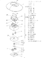
図1は本発明の第一の実施の形態による多方向操作スイッチの分解斜視図、図2は同断面図であり、同図において、21は上面に配線パターンが形成された配線基板、22は略方形の電極で、配線基板21の上面の左右に電極22がそれぞれ四つずつ設けられる。
(Embodiment 1)
FIG. 1 is an exploded perspective view of a multidirectional operation switch according to a first embodiment of the present invention, FIG. 2 is a sectional view thereof, in which 21 is a wiring board having a wiring pattern formed on its upper surface, and 22 is It is a substantially square electrode, and four
また、配線基板21の上面の略中央に半円形の電極23A、23Bが、所定の間隔を空けて、設けられている。
In addition,
また、押圧可能な自動復帰型のプッシュスイッチ3が、電極22上にハンダ付けなどで固定され、配線基板21上面に配置されている。なお、プッシュスイッチ3は特許請求の範囲に記載したスイッチの一例である。
A pushable automatic
そして、24は感圧体で、電極23Aと電極23Bの上面に所定の間隔を設けて配置され、これらの電極23Aと電極23Bと感圧体24から感圧スイッチ25が構成されている。
また、26は、ポリアセタールやナイロンなどの樹脂製の検知ピンで、下面が平坦な略円柱形状の押圧部26Aと、その上面に設けられた略円柱状の柱部26Bと、上端が丸くなった突端部26Cから構成される。
さらに、27はシリコーンゴム、イソプレンゴム、天然ゴム、クロロプレンゴム、アクリルゴム、ニトリルゴム、またはエチレンプロピレンジエンゴムなどの弾性材料で形成された下面開放で箱型の弾性体で、上面の略中央に十字状の孔27Aを備えている。
In addition,
そして、プッシュスイッチ3や感圧体24が配置された配線基板21の感圧体24の上面に検知ピン26が配置され、さらに上方から弾性体27を被せて収納されている。
And the
また、従来の多方向操作スイッチと同様に、4はポリアセタールなどの樹脂製のピン、5は下面開口のアクリロニトリルブタジエンスチレン共重合合成樹脂などの樹脂製のケースで、ケース5の上面の左右に孔5Aが、ケース5の前端、後端に側壁5Bが、側壁5Bの内側に円形に突出した軸部5Cが設けられ、前後の側壁5Bの間には角孔5Dが設けられている。
Similarly to the conventional multi-directional operation switch, 4 is a resin pin such as polyacetal, and 5 is a resin case such as acrylonitrile butadiene styrene copolymer synthetic resin having a lower surface opening. 5A is provided with a side wall 5B at the front end and the rear end of the
そして、弾性体27の上面で、左右のプッシュスイッチ3の上方となる位置にピン4を載置し、ケース5の左右の孔5Aからピン4の上端を突出させるよう、上方からケース5で覆うものとしている。
Then, on the upper surface of the
また、28はポリカーボネートなどの樹脂製の操作体で、略アーチ状の胴部28Aの左右端に押圧腕部28Bを、胴部28Aの前後端の側壁には、コの字状に凹んだ軸受部28Cを備えると共に、胴部28Aの上面に断面が略T字状の操作部28Dが形成されると共に、操作部28Dの下方の延長胴部28Aの下面から棒状の揺動部28Eが延出している。
そして、この操作体28をケース5の上方から、軸受部28Cに軸部5Cを挿入し、押圧腕部28Bの底面をピン4の上方に位置させ、揺動部28Eを角孔5Dから挿入して揺動部28Eの下端が検知ピン26の上端に接するよう組み合わせ、多方向操作スイッチ30が構成されている。
Then, the operating
さらに、図3の要部断面図を用いて、揺動部28Eと検知ピン26と感圧スイッチ25について詳細に説明する。
Furthermore, the rocking | swiveling
ここで、感圧スイッチ25を構成する感圧体24は合成樹脂内にカーボン粉を分散したシート抵抗値0.5kΩ/□〜30kΩ/□の低抵抗体層31Aをフィルム(図示せず)の下面に印刷形成し、さらに細かな凹凸が下面全面に形成されたシート抵抗値50kΩ/□〜5MΩ/□の高抵抗体層31Bを印刷形成し、そして、所定の位置に孔を空けた絶縁フィルムなどのスペーサ32を貼り付けて構成されている。
Here, the pressure-
そして、スペーサ32の孔が電極23Aおよび電極23Bの上方に位置するように、感圧体24を電極23Aおよび電極23Bの上方に所定の間隔を設けて配置することで、高抵抗体層31Bと電極23A、23Bが接離可能なものとなっている。
The pressure
これにより、感圧体24に対する押圧力を増加させるほど電極23A、23Bに対する高抵抗体層31Bの接触面積が大きくなり、電極23A、23Bとの間で高抵抗体層31Bを介した接触抵抗が小さくなる感圧スイッチ25が形成されている。
Thereby, the contact area of the high resistance layer 31B with respect to the
さらに、感圧体24の上面に、検知ピン26が平坦な押圧部26A下面で、感圧体24の上面を押圧可能なように配置されている。また、突端部26Cで揺動部28Eと接している。
Further, the
そして、揺動部28E下端が突端部26Cと接する位置には、揺動部28Eに緩やかな窪み28Fが二箇所設けられており、揺動部28Eが揺動した際に、突端部26Cが窪み28F内をスライド移動するよう構成されている。
At the position where the lower end of the swinging
このように構成された多方向操作スイッチ30が、操作部28Dを樹脂製の上面カバー11の楕円形の孔11Aから露出させて、図4の配置図で示すように自動車のステアリング41などに配置され、例えば車両のオーディオシステムやカーナビゲーションシステムなどの電子機器に用いる車両前方の中央位置のディスプレイ42や、ステアリング41前方の表示パネル43にケーブル(図示せず)などで接続される。
The
そして、操作者はディスプレイ42や表示パネル43の表示を見ながら、多方向操作スイッチ30の操作体28の操作部28Dを傾倒操作して、電子機器に所望の処理を行わせる。
Then, while viewing the display on the
このときの、多方向操作スイッチ30の動作について、図5の断面図および図6の要部断面図を用いて説明する。
The operation of the
ここで、例えば図5(a)のように、操作体28の操作部28Dに指を当てて右方向へ傾倒操作すると、操作体28は軸部5Cを軸として右方向へ傾倒する。
Here, for example, as illustrated in FIG. 5A, when the finger is placed on the
ここで、押圧腕部28Bの底面がピン4を上方から押圧し、ピン4の底面が弾性体27を介してプッシュスイッチ3を押圧して、プッシュスイッチ3をONの状態にする。
Here, the bottom surface of the
このとき、弾性体27を圧縮変形させるのに必要な力よりプッシュスイッチ3の復帰力が小さくなるよう、弾性体27の材料やプッシュスイッチ3を選定しているため、プッシュスイッチ3はONの状態で維持される。
At this time, since the material of the
また、プッシュスイッチ3が節度感を生じさせ、操作者は操作部28Dを介して、その節度感を感じとることにより、プッシュスイッチ3がONになった時点を操作者が認識することができる。
Further, the
また、操作体28の傾倒により揺動部28Eが左方向へ揺動し、図6(a)で示すように、揺動部28E下端の窪み28F内を突端部26Cの上端がスライドする。
Further, as the operating
ここで、窪み28Fがあることによって、検知ピン26の下方への移動が若干抑制されるため、感圧体24の上面は若干へこむものの押圧部26Aが感圧体24の上面を押す押圧力は抑制されている。
Here, since the downward movement of the
この時、電極23Aおよび電極23Bと高抵抗体層31Bは緩やかに接触しており、電極23Aと電極23Bの間の接触抵抗は図3の状態と比べ若干小さくなるものの、後述する図6(b)の状態より比較的大きなものとなっている。
At this time, the
つまり、操作者が、操作部28Dを押し込んで傾倒させると、まず、プッシュスイッチ3がONの状態になり節度感を感じる位置で、電極23Aおよび電極23Bと高抵抗体層31Bは緩やかに接触しており、電極23Aと電極23Bの間の接触抵抗は図3の状態と比べ若干小さくなっている。
That is, when the operator pushes the operating
そして、操作者が図5(a)の状態から操作部28Dをさらに右側に押し込んで傾倒させ、図5(b)の状態にすると、押圧腕部28Bの底面がピン4を介して、弾性体27上を押圧する。
Then, when the operator pushes the
ここで、プッシュスイッチ3は既に押されてONの状態にあるので、プッシュスイッチ3の上面は下がることがなく、プッシュスイッチ3の上面とピン4の底面の間の弾性体27が圧縮される。
Here, since the
ここで軸部5Cを中心にさらに、操作体28が傾倒しているため、揺動部28Eが揺動し、図6(b)で示すように窪み28F内を突端部26Cがスライド移動する。
Here, since the operating
なお、突端部26Cの上端は、図6(a)のように窪み28F内の一番窪んだ位置から、図6(b)のように窪み28F内をスライドして揺動部28E下端の最も突出した位置に移動しており、揺動部28Eの揺動する角度、つまり操作部28Dの傾倒角度に対して、緩急をつけた検知ピン26の押圧を可能なものとしている。
Note that the upper end of the projecting
ここで、検知ピン26が下方に移動し、高抵抗体層31Bの下面の凹凸が電極23A、23Bに押しつけられ、検知ピン26が下方に移動するほど高抵抗体層31Bと電極23A、23Bの接触面積が増加し、電極23Aと電極23Bの間の接触抵抗が減少するものとなっている。
Here, the
つまり、プッシュスイッチ3がONの状態で、さらに操作体28を傾倒させると、検知ピン26が操作体28により押圧され、検知ピン26を介して感圧体24の上面が押圧されるため、検知ピン26の押圧度合いにより感圧体24と電極23A、23Bの間の接触抵抗、ひいては電極23Aと電極23Bの間の接触抵抗が変化するものとなっている。
That is, when the operating
また、揺動部28E下端に窪み28Fを備えることにより、操作体28の傾倒角度に対して検知ピン26が下方へ移動する距離を、窪み28Fの形状を変化することで制御することができ、操作体28の傾倒角度に対する電極23Aと電極23Bの間の接触抵抗の変化を所望のものにすることができる。
Further, by providing the
なお、操作体28の操作部28Dへの操作力を解除すると、プッシュスイッチ3の復帰力と、弾性体27の弾性復帰力により図2の断面図に示す中立状態へ復帰する。
When the operating force on the
ここで、プッシュスイッチ3の復帰力より弾性体27の弾性復帰力が大きいので、プッシュスイッチ3がONを維持した状態で弾性体27が圧縮状態から復帰し、それから、プッシュスイッチ3が復帰してOFFの状態になる。
Here, since the elastic return force of the
なお、上述の説明は、操作部28Dを右に傾倒させた場合について説明したが、左に傾倒させた場合においても、多方向操作スイッチ30の動作は同様である。
In the above description, the
このような操作部28Dの操作は、例えば図7の画面図で示すような、オーディオシステムの選曲操作で行われるもので、このシステムにおいて、ディスプレイ42には円弧形状の回転ホイール51上に音符の記号が記載された複数の円形のアイコン52が表示され、アイコン52のうち若干大きく表示されたアイコン52Aが現在選択されている曲を示している。
Such an operation of the
さらに、タイトル表示部53にアイコン52Aに対応した曲名や歌手名が表示されている。
Further, the
ここで、操作部28Dを右に傾倒させて、プッシュスイッチ3がONすると、回転ホイール51が右に回転し、選択されたアイコンがアイコン52Aの左のアイコン52に順次移動する。
Here, when the
この回転ホイール51の回転速度、つまり選択されたアイコン52が隣のアイコン52に移動する速度は、電極23Aと電極23Bの間の接触抵抗が小さいほど速くなるよう、オーディオシステムのマイコンなど(図示せず)がディスプレイ42の表示を制御している。
The rotational speed of the
なお、操作部28Dを左に傾倒させた場合は、回転ホイール51が左に回転し、選択されたアイコン52が右のアイコン52に順次移動し、傾倒角度によりアイコン52の選択の移動速度を変化させることができる。
When the
つまり、操作体28の傾倒角度によりアイコン52の選択の移動速度を変化させることができるため、所望のアイコン52が遠い場合には速く移動させるために傾倒角度を大きくし、所望のアイコン52に近づくと傾倒角度を弱くしたり強くしたりしながら、選択の移動速度を遅くあるいは速くするという、操作者の要望に応じた多様な操作が可能な多方向操作スイッチ30を得ることができる。
That is, since the moving speed of selection of the
なお、上述の説明では、低抵抗体層31Aと高抵抗体層31Bを重ねて、感圧体24を形成した構成について説明したが、シリコーンゴム等の基材内にカーボン等の導電粒子を分散した感圧導電層を用い、これを電極23Aと電極23Bの上に載置した構成としても、本発明の実施は可能である。また、感圧体24は押圧力の増加に伴い、増加あるいは減少の一定の方向で、電極23Aと電極23B間の接触抵抗が変化するものであれば良い。
In the above description, the structure in which the low-
また、スイッチとしてプッシュスイッチ3を例にとり説明したが、これに限定されるものではなく、例えば操作体28でスライドスイッチを押圧してスライド操作させるものとして構成しても、本発明の実施は可能である。
The
このように本実施の形態によれば、プッシュスイッチ3などのスイッチを備えた多方向操作スイッチで、配線基板21に設けた電極22の上方に感圧体24を、感圧体24の上面に検知ピン26を配置し、操作体28で検知ピン26を押圧して、検知ピン26の押圧度合いにより感圧体24と電極22の接触抵抗を変化させることによって、接続された電子機器が多方向操作スイッチの接触抵抗の変化を反映した制御を行うことができるため、操作体28の傾倒方向、傾倒時間だけでなく、傾倒角度も反映させた容易で多様な操作の可能な多方向操作スイッチを実現することができる。
As described above, according to the present embodiment, the multi-directional operation switch including the
また、スイッチと操作体28との間に弾性体27をさらに備え、操作体28は弾性体27を介してスイッチを押圧し、弾性体27の弾性復帰力をスイッチの復帰力より大きくしているため、スイッチが押圧されてONの状態で、感圧体24を押圧するためのストロークを容易に調整可能な多方向操作スイッチを実現することができる。
Further, an
さらに、操作体28に操作部28Dの傾倒角度に応じて揺動する揺動部28Eを備え、揺動部28Eで検知ピン26を押圧するもので、揺動部28Eの検知ピン26に接触する面に窪み28Fを設けているため、操作体28の傾倒角度に対して検知ピン26が下方へ移動する距離を、窪み28Fの形状を変化することで制御することができ、操作体28の傾倒角度に対する接触抵抗の変化を所望のものにした多方向操作スイッチを実現し、多様な電子機器に対し窪み28Fの形状を変化するだけで柔軟に対応することができる。
Further, the operating
(実施の形態2)
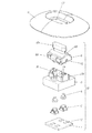
図8は本発明の第二の実施の形態による多方向操作スイッチの分解斜視図、図9は同要部断面図、図10は要部の斜視図である。
(Embodiment 2)
FIG. 8 is an exploded perspective view of a multidirectional operation switch according to the second embodiment of the present invention, FIG. 9 is a sectional view of the main part, and FIG. 10 is a perspective view of the main part.
本実施の形態は実施の形態1に対し、操作体78が前後左右に傾倒可能に構成されている点、操作体78を下方に押圧操作すると、プッシュスイッチ63Eが押圧されONになる点が主として異なる。
Compared with the first embodiment, this embodiment is mainly configured such that the operating
ここで、同図において、61は上面に配線パターンが形成された配線基板で、配線基板61の上面には、前後左右にプッシュスイッチ63A〜63Dが、プッシュスイッチ63Aとプッシュスイッチ63Bの間にプッシュスイッチ63Eが配置されている。また、プッシュスイッチ63A〜63Dで囲むように感圧スイッチ65が配置されている。なお、プッシュスイッチ63A〜63Dは特許請求の範囲に記載のスイッチの一例である。
In this figure,
ここで、感圧スイッチ65は、実施の形態1の図3を用いて上述したように、配線基板65上面に形成された電極(図示せず)と、その上方の感圧体(図示せず)により構成されるもので、感圧スイッチ65の上面に加えた押圧力により感圧体が押圧され、電極間の接触抵抗が小さくなるよう構成されている。
Here, as described above with reference to FIG. 3 of the first embodiment, the pressure-
そして、67は弾性体で、弾性体67は感圧スイッチ65の上面に重ねて配置されている。なお、弾性体67の材料としては、シリコーンゴム、イソプレンゴム、天然ゴム、クロロプレンゴム、アクリルゴム、ニトリルゴム、またはエチレンプロピレンジエンゴムなどの弾性材料が適している。
さらに、68は略円筒状でその一方向が突出した支持体、69は棒状の傾動体、70はドーム状の底面の前後左右方向が突出した可動体である。ここで、支持体68の突出部68Aの上面には略半円状の凹み部68Bが設けられ、傾動体69には一端に設けられた円筒状の支点部69Aが凹み部68Bに嵌め込まれ支持体68上で傾動体69が傾動可能に構成されている。
Further, 68 is a substantially cylindrical support body that protrudes in one direction, 69 is a rod-like tilting body, and 70 is a movable body that projects in the front-rear and left-right directions of the dome-shaped bottom surface. Here, a substantially
また、傾動体69の支点部69Aに対し逆側の端部は、プッシュスイッチ63E上方に配置され、傾動体69の傾動によりプッシュスイッチ63Eが押圧されるよう構成されている。
Further, the end of the tilting
また、可動体70はその上面に穴部70Aが、下面に四個の下方向に突出した押圧部70Bが設けられると共に、前後左右に突出した板状の傾動部70Cが備えられている。そして、可動体70は傾動体69を挟むように支持体68に組み合わされており、可動体70が支持体68上で前後左右に傾動すると、傾動方向の傾動部70Cがプッシュスイッチ63A〜63Dを押圧し、傾動方向の押圧部70Bが弾性体67を介して感圧スイッチ65を押圧するよう構成されている。
The
なお、支持体68、傾動体69、可動体70の材料としては、アクリロニトリルブタジエンスチレン共重合合成樹脂、ポリアセタール、ナイロン、ポリカーボネートなどの樹脂が好適である。
In addition, as a material of the
そして、71は下側ケース、72は上側ケースで、下側ケース71と上側ケース72の間に、配線基板61上に弾性体67、支持体68、傾動体69、可動体70が組合わされて配置され、上側ケース72に設けられた孔部72Aから可動体70の上面を露出させている。
71 is a lower case, 72 is an upper case, and an
さらに、78は湾曲した板状の上面カバー、79はピン状の操作体で、上側ケース72上方から上面カバー78で覆われると共に、操作体79は可動体70の穴部70Aに、その下端が挿入されて、多方向操作スイッチ80が構成されている。
Further, 78 is a curved plate-shaped upper surface cover, 79 is a pin-shaped operation body, and is covered with the upper surface cover 78 from above the
なお、下側ケース71、上側ケース72、上面カバー78、操作体79の材料は、アクリロニトリルブタジエンスチレン共重合合成樹脂、ポリアセタール、ナイロン、ポリカーボネートなどの樹脂が好適である。
The material of the
つまり、操作体79を傾倒操作すると、四つのプッシュスイッチ63A〜63Dのうち傾倒方向に対応したものが押圧されONになるよう構成されると共に、感圧スイッチ65も押圧されるよう構成されている。
That is, when the
また、操作体79を下方向に押圧操作すると、傾動体69が傾動しプッシュスイッチ63Eを押圧し、プッシュスイッチ63EがONするよう構成されている。
Further, when the operating
次に、図11および図12の要部断面図を用いて、操作者が操作体79を傾倒操作、押圧操作した際の動作について説明する。
Next, the operation when the operator tilts and presses the operating
図11は、操作体79を右方向に傾倒操作したときの要部断面図で、操作体79が接続された可動体70も右方向に回転し、傾動部70Cによりプッシュスイッチ63Bが押圧され、プッシュスイッチ63BがONする。この時、押圧部70Bは弾性体67の上面を押圧しているが、押圧力は僅かである。そして、操作者が操作体79をさらに右方向に傾倒操作すると、傾倒角度の増加に対応して、押圧部70Bの押圧力が増し、それと共に感圧スイッチ65の感圧体の押圧力も増加し、感圧スイッチ65が検知するものとなっている。
FIG. 11 is a cross-sectional view of the main part when the operating
なお、前後左右の四方向に操作体79を傾倒操作した場合は、操作体79の傾倒方向が変化し、それぞれの傾倒方向に対応したプッシュスイッチ63A〜63DがONする。また、前後左右の中間位置の斜め方向に操作体79を傾倒操作した場合は、プッシュスイッチ63A〜63Dのうち傾倒操作方向を挟む二つがONするため、多方向操作スイッチ80は計八方向の操作が可能である。
Note that when the operating
また、図12は、操作体79を下方向に押圧操作したときの要部断面図で、操作体79が接続された可動体70も下方向に移動し、可動体70に押圧された傾動体69が傾動し、プッシュスイッチ63Eが押圧され、プッシュスイッチ63EがONする。
FIG. 12 is a cross-sectional view of the main part when the operating
このような操作体79の操作は、例えば、カーナビゲーションシステムの地図の表示画面上で、目的地を設定するためのポインタを移動させる場合に行われる。その場合、カーナビゲーションシステムのマイコンは、多方向操作スイッチ80のプッシュスイッチ63A〜63DがONしたこと、および感圧スイッチ65の押圧力を検出する。
Such an operation of the operating
そして、カーナビゲーションシステムのマイコンは、地図の表示画面上でポインタを、操作体79が操作された方向に、また操作体79の傾倒角度に応じた速さで移動して表示する。そして、操作体79を下方向に押圧すると、プッシュスイッチ63EがONして目的地の確定などを行うものである。
Then, the microcomputer of the car navigation system displays the pointer on the map display screen by moving the pointer in the direction in which the operating
このように本実施の形態によれば、配線基板61には例えばプッシュスイッチ63A〜63Dの少なくとも四つのスイッチが配置され、感圧体は感圧スイッチ65を構成する一つで、スイッチのいずれかが押圧された後、さらに操作体79を傾倒操作すると感圧体の押圧力が増加するもので、四方向以上の方向に対応した多方向操作スイッチ80においても、感圧体は一つで対応できるため、簡易な構成で、より多様な操作の可能な多方向操作スイッチを実現することができる。
As described above, according to the present embodiment, at least four switches, for example, push switches 63A to 63D are arranged on the
本発明による多方向操作スイッチは、容易に多様な操作の可能なものを実現することができるという有利な効果を有し、主に各種電子機器の操作用として有用である。 The multi-directional operation switch according to the present invention has an advantageous effect that it can easily realize various operations and is useful mainly for operation of various electronic devices.
3、63A〜63E プッシュスイッチ
4 ピン
5 ケース
5A 孔
5B 側壁
5C 軸部
5D 角孔
11、78 上面カバー
11A 孔
21、61 配線基板
22、23A、23B 電極
24 感圧体
25、65 感圧スイッチ
26 検知ピン
26A 押圧部
26B 柱部
26C 突端部
27、67 弾性体
27A 孔
28、79 操作体
28A 胴部
28B 押圧腕部
28C 軸受部
28D 操作部
28E 揺動部
28F 窪み
30、80 多方向操作スイッチ
41 ステアリング
42 ディスプレイ
43 表示パネル
51 回転ホイール
52、52A アイコン
53 タイトル表示部
68 支持体
68A 突出部
68B 凹み部
69 傾動体
69A 支点部
70 可動体
70A 穴部
70B 押圧部
70C 傾動部
71 下側ケース
72 上側ケース
72A 孔部
3, 63A to
Claims (3)
Priority Applications (2)
| Application Number | Priority Date | Filing Date | Title |
|---|---|---|---|
| JP2010254684A JP5617552B2 (en) | 2010-06-11 | 2010-11-15 | Multi-directional operation switch |
| US13/153,581 US8586882B2 (en) | 2010-06-11 | 2011-06-06 | Multi-directional switch |
Applications Claiming Priority (3)
| Application Number | Priority Date | Filing Date | Title |
|---|---|---|---|
| JP2010133633 | 2010-06-11 | ||
| JP2010133633 | 2010-06-11 | ||
| JP2010254684A JP5617552B2 (en) | 2010-06-11 | 2010-11-15 | Multi-directional operation switch |
Publications (2)
| Publication Number | Publication Date |
|---|---|
| JP2012018901A JP2012018901A (en) | 2012-01-26 |
| JP5617552B2 true JP5617552B2 (en) | 2014-11-05 |
Family
ID=45095338
Family Applications (1)
| Application Number | Title | Priority Date | Filing Date |
|---|---|---|---|
| JP2010254684A Expired - Fee Related JP5617552B2 (en) | 2010-06-11 | 2010-11-15 | Multi-directional operation switch |
Country Status (2)
| Country | Link |
|---|---|
| US (1) | US8586882B2 (en) |
| JP (1) | JP5617552B2 (en) |
Families Citing this family (12)
| Publication number | Priority date | Publication date | Assignee | Title |
|---|---|---|---|---|
| JP6421329B2 (en) * | 2012-08-08 | 2018-11-14 | パナソニックIpマネジメント株式会社 | Operation switch |
| US11185763B2 (en) | 2016-10-11 | 2021-11-30 | Valve Corporation | Holding and releasing virtual objects |
| US10987573B2 (en) | 2016-10-11 | 2021-04-27 | Valve Corporation | Virtual reality hand gesture generation |
| US11625898B2 (en) | 2016-10-11 | 2023-04-11 | Valve Corporation | Holding and releasing virtual objects |
| US10691233B2 (en) | 2016-10-11 | 2020-06-23 | Valve Corporation | Sensor fusion algorithms for a handheld controller that includes a force sensing resistor (FSR) |
| US10888773B2 (en) * | 2016-10-11 | 2021-01-12 | Valve Corporation | Force sensing resistor (FSR) with polyimide substrate, systems, and methods thereof |
| US10898797B2 (en) | 2016-10-11 | 2021-01-26 | Valve Corporation | Electronic controller with finger sensing and an adjustable hand retainer |
| US10307669B2 (en) | 2016-10-11 | 2019-06-04 | Valve Corporation | Electronic controller with finger sensing and an adjustable hand retainer |
| US10391400B1 (en) | 2016-10-11 | 2019-08-27 | Valve Corporation | Electronic controller with hand retainer and finger motion sensing |
| JP2018129193A (en) * | 2017-02-08 | 2018-08-16 | 株式会社デンソー | Switch device |
| US10874939B2 (en) | 2017-06-16 | 2020-12-29 | Valve Corporation | Electronic controller with finger motion sensing |
| CN112219246B (en) * | 2018-05-18 | 2023-02-21 | 威尔乌集团 | Force sensing resistor (FSR) with polyimide substrate, system and method thereof |
Family Cites Families (13)
| Publication number | Priority date | Publication date | Assignee | Title |
|---|---|---|---|---|
| JPS606974Y2 (en) * | 1978-05-22 | 1985-03-07 | ナイルス部品株式会社 | Car remote control mirror switch |
| US6347997B1 (en) * | 1997-10-01 | 2002-02-19 | Brad A. Armstrong | Analog controls housed with electronic displays |
| JP3494922B2 (en) * | 1999-06-04 | 2004-02-09 | アルプス電気株式会社 | Game device input device |
| US6313731B1 (en) * | 2000-04-20 | 2001-11-06 | Telefonaktiebolaget L.M. Ericsson | Pressure sensitive direction switches |
| JP3903731B2 (en) * | 2000-08-03 | 2007-04-11 | 松下電器産業株式会社 | Multi-directional input device and electronic apparatus using the same |
| JP2002278695A (en) * | 2001-03-15 | 2002-09-27 | Hosiden Corp | Multi-directional input device |
| JP4029701B2 (en) * | 2002-09-09 | 2008-01-09 | 松下電器産業株式会社 | Multi-directional input device |
| US7310084B2 (en) | 2004-06-29 | 2007-12-18 | Matsushita Electric Industrial Co., Ltd. | Multi-way operation switch, input device and input unit |
| JP4046107B2 (en) * | 2004-06-29 | 2008-02-13 | 松下電器産業株式会社 | Multi-directional operation switch |
| JP4729991B2 (en) * | 2005-06-13 | 2011-07-20 | パナソニック株式会社 | Electronics |
| EP2001034A3 (en) * | 2007-06-04 | 2009-12-30 | Panasonic Corporation | Movable Contact Element and Switch Using the Same |
| DE102007051466A1 (en) * | 2007-10-27 | 2009-04-30 | Rafi Gmbh & Co. Kg | switching device |
| JP2009211902A (en) * | 2008-03-04 | 2009-09-17 | Alps Electric Co Ltd | Multidirectional input device |
-
2010
- 2010-11-15 JP JP2010254684A patent/JP5617552B2/en not_active Expired - Fee Related
-
2011
- 2011-06-06 US US13/153,581 patent/US8586882B2/en active Active
Also Published As
| Publication number | Publication date |
|---|---|
| JP2012018901A (en) | 2012-01-26 |
| US20110303519A1 (en) | 2011-12-15 |
| US8586882B2 (en) | 2013-11-19 |
Similar Documents
| Publication | Publication Date | Title |
|---|---|---|
| JP5617552B2 (en) | Multi-directional operation switch | |
| US10840041B1 (en) | Multifunctional control element | |
| JP2026004303A (en) | Controller with sensor-rich control device | |
| JP2916842B2 (en) | Screen display control device | |
| JP5326569B2 (en) | Input device | |
| EP1196887B1 (en) | Joystick controller | |
| US20080257701A1 (en) | Multifunctional rotary switch | |
| JP2004087290A (en) | Multi-directional input device | |
| JPH10214128A (en) | Joystick type multi-function controller | |
| CN101276700A (en) | Multi-directional input device and electronic equipment | |
| US7820924B2 (en) | Multi-direction switch for a cursor device | |
| JP4673695B2 (en) | Interface device | |
| JP4700432B2 (en) | Vehicle control device | |
| JP6421329B2 (en) | Operation switch | |
| CN1465004A (en) | Multi directional input device and electronic equipment using the device | |
| JP6329932B2 (en) | Vehicle operation system | |
| JP2019160457A (en) | Switch and multidirectional input device with the same | |
| JP2006012695A (en) | Multi-directional operation switch | |
| JP4732056B2 (en) | Vehicle control device | |
| JP2004139845A (en) | Inner force sense applying type input device | |
| JP2010021118A (en) | Switch structure | |
| JP4624973B2 (en) | Shift device | |
| JP2002108557A (en) | Joystick device | |
| CN100485841C (en) | Electronic device | |
| CN115210836A (en) | Multi-directional input device |
Legal Events
| Date | Code | Title | Description |
|---|---|---|---|
| A621 | Written request for application examination |
Free format text: JAPANESE INTERMEDIATE CODE: A621 Effective date: 20131028 |
|
| RD01 | Notification of change of attorney |
Free format text: JAPANESE INTERMEDIATE CODE: A7421 Effective date: 20131113 |
|
| RD01 | Notification of change of attorney |
Free format text: JAPANESE INTERMEDIATE CODE: A7421 Effective date: 20140108 |
|
| RD01 | Notification of change of attorney |
Free format text: JAPANESE INTERMEDIATE CODE: A7421 Effective date: 20140418 |
|
| A977 | Report on retrieval |
Free format text: JAPANESE INTERMEDIATE CODE: A971007 Effective date: 20140528 |
|
| A131 | Notification of reasons for refusal |
Free format text: JAPANESE INTERMEDIATE CODE: A131 Effective date: 20140603 |
|
| A521 | Request for written amendment filed |
Free format text: JAPANESE INTERMEDIATE CODE: A523 Effective date: 20140723 |
|
| TRDD | Decision of grant or rejection written | ||
| A01 | Written decision to grant a patent or to grant a registration (utility model) |
Free format text: JAPANESE INTERMEDIATE CODE: A01 Effective date: 20140819 |
|
| A61 | First payment of annual fees (during grant procedure) |
Free format text: JAPANESE INTERMEDIATE CODE: A61 Effective date: 20140901 |
|
| R151 | Written notification of patent or utility model registration |
Ref document number: 5617552 Country of ref document: JP Free format text: JAPANESE INTERMEDIATE CODE: R151 |
|
| LAPS | Cancellation because of no payment of annual fees |