JP5617484B2 - Water-soluble component removal device - Google Patents
Water-soluble component removal device Download PDFInfo
- Publication number
- JP5617484B2 JP5617484B2 JP2010214891A JP2010214891A JP5617484B2 JP 5617484 B2 JP5617484 B2 JP 5617484B2 JP 2010214891 A JP2010214891 A JP 2010214891A JP 2010214891 A JP2010214891 A JP 2010214891A JP 5617484 B2 JP5617484 B2 JP 5617484B2
- Authority
- JP
- Japan
- Prior art keywords
- water
- wet filter
- soluble component
- air
- tray
- Prior art date
- Legal status (The legal status is an assumption and is not a legal conclusion. Google has not performed a legal analysis and makes no representation as to the accuracy of the status listed.)
- Active
Links
Images


Classifications
-
- A—HUMAN NECESSITIES
- A61—MEDICAL OR VETERINARY SCIENCE; HYGIENE
- A61L—METHODS OR APPARATUS FOR STERILISING MATERIALS OR OBJECTS IN GENERAL; DISINFECTION, STERILISATION OR DEODORISATION OF AIR; CHEMICAL ASPECTS OF BANDAGES, DRESSINGS, ABSORBENT PADS OR SURGICAL ARTICLES; MATERIALS FOR BANDAGES, DRESSINGS, ABSORBENT PADS OR SURGICAL ARTICLES
- A61L9/00—Disinfection, sterilisation or deodorisation of air
- A61L9/16—Disinfection, sterilisation or deodorisation of air using physical phenomena
-
- B—PERFORMING OPERATIONS; TRANSPORTING
- B01—PHYSICAL OR CHEMICAL PROCESSES OR APPARATUS IN GENERAL
- B01D—SEPARATION
- B01D53/00—Separation of gases or vapours; Recovering vapours of volatile solvents from gases; Chemical or biological purification of waste gases, e.g. engine exhaust gases, smoke, fumes, flue gases, aerosols
- B01D53/14—Separation of gases or vapours; Recovering vapours of volatile solvents from gases; Chemical or biological purification of waste gases, e.g. engine exhaust gases, smoke, fumes, flue gases, aerosols by absorption
Description
本発明は、ホルムアルデヒド、アセトアルデヒド、アンモニア、アルコールなどの空気中の水溶性成分を連続的に除去する水溶性成分除去装置に関する。 The present invention relates to a water-soluble component removing apparatus that continuously removes water-soluble components in air such as formaldehyde, acetaldehyde, ammonia, and alcohol.
室内空気には、調理で発生するアセトアルデヒドなどの調理臭、野菜や発酵食品等から発生するエタノールや酢酸などの芳香臭、建材や家具等から発生するホルムアルデヒドやアセトンなどの化学物質が存在している。これらの成分は、人に不快感を与え、長期間吸引すると頭痛などの障害を起こす可能性があり、室内空気から除去することが望まれている。前記成分は水に溶解する性質をもっており、室内空気を水と接触させることによって除去が可能である。 The indoor air contains cooking odors such as acetaldehyde generated during cooking, aromatic odors such as ethanol and acetic acid generated from vegetables and fermented foods, and chemical substances such as formaldehyde and acetone generated from building materials and furniture. . These components are uncomfortable for humans and may cause problems such as headaches when inhaled for a long period of time, and it is desired to remove them from room air. The component has a property of dissolving in water and can be removed by bringing indoor air into contact with water.
従来、この種のガス処理方法として、ホルムアルデヒドを含む排ガスを洗浄塔で吸収させた洗浄液の一部または全量を、オゾン酸化によって酸化分解して除去し、その液を洗浄塔へ送り返して循環使用するものが知られていた。すなわち、ホルムアルデヒドは水によく溶解するため、洗浄塔の上部に設置された液分配管から噴霧される水と排ガスが気液接触することにより、排ガス中に含まれるホルムアルデヒドが水に吸収除去される。次いで、ホルムアルデヒドを吸収した水が、ポンプによってオゾン酸化槽に送られ、オゾンと接触反応することによって除去されるものであった(例えば、特許文献1参照)。 Conventionally, as this type of gas treatment method, part or all of the cleaning liquid in which the exhaust gas containing formaldehyde is absorbed by the cleaning tower is removed by oxidative decomposition by ozone oxidation, and the liquid is sent back to the cleaning tower for circulation. Things were known. That is, since formaldehyde dissolves well in water, the water sprayed from the liquid pipe installed in the upper part of the washing tower and the exhaust gas come into gas-liquid contact, so that the formaldehyde contained in the exhaust gas is absorbed and removed by the water. . Subsequently, the water which absorbed formaldehyde was sent to an ozone oxidation tank by a pump and removed by contact reaction with ozone (for example, refer to Patent Document 1).
また、従来、燃焼排ガスより生じた結露水を利用して加湿を行う加湿装置として、加湿水に含まれるホルムアルデヒドやアセトアルデヒドやケトン類を電気分解によって分解する方法が知られていた。図3に示すように、石油温風機101は、オイルタンク102から送油された灯油を、バーナー103で燃焼し、熱交換器104と熱交換パイプ105を経由して屋外に排気するとともに、ファン106によって熱交換器104と熱交換パイプ105の外表面に空気を送り、温風による暖房を行うものである。タンク107に集められた結露水は、加湿パイプ108を介して加湿皿109へ送られ、ここで蒸発されて加湿口110から室内へ水蒸気が送られ、加湿される。ここで、燃焼ガスを結露させた結露水には、微量のホルムアルデヒド、アセトアルデヒド、ケトン類などが含まれており、これらの成分が水蒸気とともに室内に拡散すると、不快あるいは刺激のある臭気によって使用者に不快感を与えてしまうという課題があったが、タンク107に陽極と陰極からなる電気分解装置を備えることによって、臭気の分解除去を行うものであった(例えば、特許文献2参照)。
Conventionally, a method of decomposing formaldehyde, acetaldehyde, and ketones contained in humidified water by electrolysis has been known as a humidifier that performs humidification using dew condensation water generated from combustion exhaust gas. As shown in FIG. 3, the oil warm air machine 101 burns kerosene sent from the
しかしながら、従来のガス処理方法では、液分配管から噴霧される水と排ガスの気液接触によるホルムアルデヒドの吸収効率が十分ではなく、より効率的なホルムアルデヒド除去方法が求められていた。また、水を噴霧する際やポンプの送液時には騒音が発生しやすく、より作動音の静かなホルムアルデヒド除去方法が求められていた。また、オゾンによる酸化反応では、反応しきれなかったオゾンが気中に放出され、配管の腐食やオゾン臭による不快感などが発生しやすいという課題があった。 However, in the conventional gas treatment method, the absorption efficiency of formaldehyde due to the gas-liquid contact between the water sprayed from the liquid pipe and the exhaust gas is not sufficient, and a more efficient formaldehyde removal method has been demanded. Further, there has been a demand for a formaldehyde removal method that is easy to generate noise when water is sprayed or when a pump is pumped, and has a quieter operation sound. In addition, in the oxidation reaction with ozone, ozone that could not be reacted is released into the air, and there is a problem that corrosion of pipes and discomfort due to ozone odor are likely to occur.
また、従来の加湿装置では、石油温風機の燃焼ガスを結露させた加湿水に含まれるアルデヒド類を電気分解することを目的としており、空気中のアルデヒドなどの水溶性成分を積極的に除去する目的に転用しても十分な効果は得られなかった。 In addition, the conventional humidifier is intended to electrolyze aldehydes contained in the humidified water that has condensed the combustion gas of the oil hot air machine, and actively removes water-soluble components such as aldehyde in the air. Even if diverted to the purpose, a sufficient effect was not obtained.
そこで本発明は、上記従来の課題を解決するものであり、空気中のアルデヒド類などの水溶性成分を効率的に除去できる水溶性成分除去装置を提供することを目的とする。 Therefore, the present invention solves the above-described conventional problems, and an object of the present invention is to provide a water-soluble component removing apparatus that can efficiently remove water-soluble components such as aldehydes in the air.
この目的を達成するために、本発明は、空気の吸込口と吹出口を有する本体と、この吸込口と吹出口を連通する風路内に、前記吸込口より吸い込んだ空気中の水溶性成分を溶解させるための湿潤フィルタと、前記湿潤フィルタを配置し水を貯めるためのトレイと、前記湿潤フィルタに水を供給するための水供給手段と、前記湿潤フィルタに空気を送る送風手段と、前記トレイに前記湿潤フィルタに溶解させた水溶性成分が溶解したガス成分を電気分解する電極とを備えた水溶性成分除去装置であって、前記湿潤フィルタが回動可能であり、前記湿潤フィルタの少なくとも一部がトレイの水に浸漬され、前記湿潤フィルタの回動により前記湿潤フィルタが水没する側と上昇する側が前記トレイ内に形成され、前記トレイ内において、前記湿潤フィルタの下方に隔壁を備え、前記湿潤フィルタの水没する側と上昇する側の水の移動を前記隔壁が制限することで、前記トレイの水に含まれる水溶性成分に濃度差を発生させるとともに、水溶性成分の濃度が高くなるようにした水域に、前記電極を備えたことを特徴としたものである。これにより所期の目的を達成することができる。 In order to achieve this object, the present invention provides a water-soluble component in the air sucked from the suction port into a main body having an air suction port and a blower outlet, and an air passage communicating the suction port and the blower outlet. A wet filter for dissolving the water, a tray for disposing the wet filter and storing water, a water supply means for supplying water to the wet filter, a blower means for sending air to the wet filter, and A water-soluble component removing device comprising a tray and an electrode for electrolyzing a gas component in which a water-soluble component dissolved in the wet filter is dissolved, wherein the wet filter is rotatable, and at least the wet filter part of which is immersed in the water of the tray, the side where the wet filter by the rotation of the wet filter is raised to the side where submerged is formed in said tray in said tray, said wet off Comprising a partition wall below the filter, the movement of the side of the water rising to the side where submerged the wet filter that the partition wall limits, together to generate a density difference in the water-soluble components contained in the water of the tray, the water concentration of the water-soluble component was higher due so, is obtained by comprising the above electrode. As a result, the intended purpose can be achieved.
本発明によれば、空気中のアルデヒド類などの水溶性成分を効率的に除去できる水溶性成分除去装置を提供することができる。 ADVANTAGE OF THE INVENTION According to this invention, the water-soluble component removal apparatus which can remove efficiently water-soluble components, such as aldehydes in air, can be provided.
本発明の水溶性成分除去装置は、空気の吸込口と吹出口を有する本体と、この吸込口と吹出口を連通する風路内に、前記吸込口より吸い込んだ空気中の水溶性成分を溶解させるための湿潤フィルタと、前記湿潤フィルタを配置し水を貯めるためのトレイと、前記湿潤フィルタに水を供給するための水供給手段と、前記湿潤フィルタに空気を送る送風手段と、前記トレイに前記湿潤フィルタに溶解させた水溶性成分が溶解したガス成分を電気分解する電極とを備えた水溶性成分除去装置であって、前記湿潤フィルタが回動可能であり、前記湿潤フィルタの少なくとも一部がトレイの水に浸漬され、前記湿潤フィルタの回動により前記湿潤フィルタが水没する側と上昇する側が前記トレイ内に形成され、前記トレイ内において、前記湿潤フィルタの下方に隔壁を備え、前記湿潤フィルタの水没する側と上昇する側の水の移動を前記隔壁が制限することで、前記トレイの水に含まれる水溶性成分に濃度差を発生させるとともに、水溶性成分の濃度が高くなるようにした水域に、前記電極を備えたことを特徴としたものである。 The water-soluble component removing device of the present invention dissolves water-soluble components in the air sucked from the suction port into a main body having an air suction port and a blow-off port, and an air passage communicating the suction port and the blow-out port. A wet filter, a tray for arranging the wet filter and storing water, a water supply means for supplying water to the wet filter, a blower means for sending air to the wet filter, and the tray An apparatus for electrolyzing a gas component in which a water-soluble component dissolved in the wet filter is dissolved, wherein the wet filter is rotatable, and at least a part of the wet filter There are immersed in water of the tray, the side where the wet filter by the rotation of the wet filter is raised to the side where submerged is formed in said tray in said tray, said wet filter Comprising a septum downwardly moving side of the water rising to the side where submerged the wet filter that the partition wall limits, together to generate a density difference in the water-soluble components contained in the water of the tray, water-soluble the water concentration of the components was higher due so, is obtained by comprising the above electrode.
例えば、網状のフィルタを、微細な開口を有するウレタン発泡体に変更することによって、表面積を増加させて気液接触面積を向上させることができる。また、水をフィルタ上に安定的に保持できるので、気液接触時間を長くすることも可能である。一方、水を噴霧する方法では、水滴の大きさが数mm程度で表面積が小さいため、気体との接触効率が悪い。水を高圧ノズルで粉砕することで、大きさを0.05〜0.1mm程度まで小さくすることができるが、この場合、水を破砕することによる騒音が発生してしまうという課題があった。また、水を噴霧する方法では、噴霧された水は重力の作用で短時間に落下してしまうため、気液接触時間を調節するには装置を大型化して落下時間を長くする必要があり、小型の水溶性成分除去装置を得ることは困難であった。 For example, by changing the net-like filter to a urethane foam having fine openings, the surface area can be increased and the gas-liquid contact area can be improved. Moreover, since water can be stably held on the filter, the gas-liquid contact time can be extended. On the other hand, in the method of spraying water, since the size of the water droplet is about several millimeters and the surface area is small, the contact efficiency with the gas is poor. By crushing water with a high-pressure nozzle, the size can be reduced to about 0.05 to 0.1 mm. However, in this case, there is a problem that noise is generated by crushing water. Also, in the method of spraying water, the sprayed water falls in a short time due to the action of gravity, so in order to adjust the gas-liquid contact time, it is necessary to enlarge the device and lengthen the fall time, It was difficult to obtain a small water-soluble component removing device.
従って、湿潤したフィルタに水溶性成分を含む空気を通過させる方法により、水を噴霧する従来の気液接触方式に比べてホルムアルデヒドなどの水溶性成分との接触効率を向上させ、より効率的に水溶性成分を除去できるという効果を得ることができる。湿潤フィルタ上の水に捕集した水溶性成分は、湿潤フィルタがトレイの水に浸漬された瞬間にトレイの水に移行し、新たに湿潤フィルタに、水溶性成分をほとんど含まない水が補充されることによって、連続的に水溶性成分を捕集することができる。トレイの水に移行した水溶性成分は、電極によって電気分解される。電極は、水溶性成分の濃度が高い水域に配置されているため、電気分解の効率が良いという効果を得ることができる。また、湿潤フィルタに空気を通過させる方式なので、水の噴霧やポンプでの送液をする必要がなく、作動音が静かであるという効果を得ることができる。また、オゾン等の有臭の酸化性物質を使用しないため、配管の腐食やオゾン臭による不快感などが発生しないという効果を得ることができる。 Therefore, the method of allowing air containing water-soluble components to pass through a wet filter improves the contact efficiency with water-soluble components such as formaldehyde compared to the conventional gas-liquid contact method in which water is sprayed, making water more efficient. The effect that the sex component can be removed can be obtained. Water-soluble components collected in the water on the wet filter are transferred to the tray water as soon as the wet filter is immersed in the water in the tray, and the wet filter is newly replenished with water containing almost no water-soluble components. Thus, water-soluble components can be continuously collected. The water-soluble component transferred to the water in the tray is electrolyzed by the electrode. Since the electrode is disposed in the water area where the concentration of the water-soluble component is high, an effect of good electrolysis efficiency can be obtained. In addition, since air is passed through the wet filter, there is no need to spray water or feed liquid with a pump, and an effect that the operation sound is quiet can be obtained. In addition, since no odorous oxidant such as ozone is used, it is possible to obtain the effect that the pipes are not corroded or uncomfortable due to the ozone odor.
特に、湿潤フィルタの下方に隔壁を備え、前記隔壁によって水に含まれる水溶性成分に濃度差を発生させることを特徴としたものである。隔壁によってトレイの水の移動を制限することができ、水に含まれる水溶性成分に濃度差を発生させることができる。 In particular , a partition is provided below the wet filter, and the partition generates a concentration difference in water-soluble components contained in water. The movement of the water in the tray can be restricted by the partition wall, and a concentration difference can be generated in the water-soluble component contained in the water.
以下、本発明の実施の形態について図面を参照しながら説明する。 Hereinafter, embodiments of the present invention will be described with reference to the drawings.
(実施の形態1)
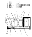
本発明の実施の形態1の水溶性成分除去装置は、図1に示すように、空気の吸込口1と吹出口2を有する本体3と、この吸込口1と吹出口2を連通する風路内に、水溶性成分を溶解させるための湿潤フィルタ4と、前記湿潤フィルタ4を配置し水を貯めるためのトレイ5と、前記湿潤フィルタ4に水を供給するための水供給手段としての水タンク6と、前記湿潤フィルタ4に空気を送る送風手段としてのファン7と、水に溶解したガス成分を電気分解する電極8とを備えた水溶性成分除去装置である。前記湿潤フィルタ4は回動可能であり、前記湿潤フィルタ4の少なくとも一部はトレイ5の水に浸漬され、前記トレイ5の水に含まれる水溶性成分に濃度差を発生させるとともに、水溶性成分の濃度が高い水域に、前記電極8を備えている。また、湿潤フィルタ4の下方には隔壁9を備え、前記隔壁9によってトレイの水の自由な移動は制限されている。
(Embodiment 1)
As shown in FIG. 1, the water-soluble component removing apparatus according to
このような構成とすることにより、水を噴霧する気液接触方式に比べてホルムアルデヒドなどの水溶性成分との接触効率を向上させ、より効率的に水溶性成分を除去できるという効果を得ることができる。 By adopting such a configuration, it is possible to improve the contact efficiency with a water-soluble component such as formaldehyde as compared with a gas-liquid contact method in which water is sprayed, and to obtain an effect that the water-soluble component can be removed more efficiently. it can.
例えば、水を噴霧する方法では、水滴の大きさが数mm程度で表面積が小さいため、気体との接触効率が悪い。水を高圧ノズルで粉砕することで、大きさを0.05〜0.1mm程度まで小さくすることができるが、この場合、水を破砕することによる騒音が発生してしまうという課題があった。また、水を噴霧する方法では、噴霧された水は重力の作用で短時間に落下してしまうため、気液接触時間を調節するには装置を大型化して落下時間を長くする必要があり、小型の水溶性成分除去装置を得ることは困難であった。 For example, in the method of spraying water, since the size of the water droplet is about several millimeters and the surface area is small, the contact efficiency with the gas is poor. By crushing water with a high-pressure nozzle, the size can be reduced to about 0.05 to 0.1 mm. However, in this case, there is a problem that noise is generated by crushing water. Also, in the method of spraying water, the sprayed water falls in a short time due to the action of gravity, so in order to adjust the gas-liquid contact time, it is necessary to enlarge the device and lengthen the fall time, It was difficult to obtain a small water-soluble component removing device.
本実施の形態の、湿潤したフィルタに水溶性成分を含む空気を通過させる方法では、例えば、網状のフィルタを、微細な開口を有するウレタン発泡体に変更することによって、表面積を増加させて気液接触面積を向上させることができる。また、水をフィルタ上に安定的に保持できるので、気液接触時間を長くすることも可能である。また、水の噴霧やポンプでの送液をする必要がないため、水の破砕音や装置壁面への衝突音が発生せず、静かな装置とすることができる。また、湿潤フィルタを表面積の大きい形状に変更する、あるいは厚みを厚くすることによって、気液接触面積を向上させ、水溶性成分除去効率を向上させるという効果を得ることができる。 In the method of passing air containing a water-soluble component through a wet filter according to the present embodiment, for example, by changing the net-like filter to a urethane foam having fine openings, the surface area is increased and the gas-liquid is increased. The contact area can be improved. Moreover, since water can be stably held on the filter, the gas-liquid contact time can be extended. In addition, since it is not necessary to spray water or feed with a pump, there is no crushing sound of water or a collision sound with the apparatus wall surface, and the apparatus can be made quiet. Further, by changing the wet filter into a shape having a large surface area or increasing the thickness, it is possible to obtain an effect of improving the gas-liquid contact area and improving the water-soluble component removal efficiency.
湿潤フィルタ4は回動可能であり、湿潤フィルタ4の回動方向は、吸込空気に対して下流側から上昇し、上流側で水没する向きとなっている。このような回動方向にすることにより、吸込口1から吸い込まれた水溶性成分を含む空気は、わずかに水溶性成分が溶解した湿潤フィルタ4aの部分(図1の一点破線の左側)を通過した後、水溶性成分をほとんど含まない湿潤フィルタ4bの部分(図1の一点破線の右側)を通過することになるため、水から水溶性成分が再揮発する恐れが少なく、捕集効率がよいという効果を得ることができる。
The
例えば、水溶性成分として、ホルムアルデヒドは水に非常によく溶けることが知られており、水への溶解度は55%である。また、ヘンリー定数は0.0341 Pa・m3/mol (25℃) と小さく、一度溶け込んだホルムアルデヒドは水から大気へ揮散され難くなっている。わずかに揮発するホルムアルデヒドも、水溶性成分をほとんど含まない湿潤フィルタ4bの部分(図1の一点破線の右側)を通過することによって捕集され、装置の吹出口からは清浄な空気が放出される。湿潤フィルタが、自重と同程度の水を保持することができると過程すると、半径5cmで幅10cm、厚み1cmのフィルタでは約304mlの水を保持でき、ホルムアルデヒドを167ml分吸収できることになる。
For example, as a water-soluble component, formaldehyde is known to dissolve very well in water, and its solubility in water is 55%. Further, the Henry's constant is as small as 0.0341 Pa · m 3 / mol (25 ° C.), and once dissolved, formaldehyde is hardly evaporated from water to the atmosphere. Slightly volatile formaldehyde is collected by passing through the portion of the
湿潤フィルタ4aの部分で水に捕集された水溶性成分は、湿潤フィルタ4がトレイの水に浸漬された瞬間にトレイの水に移行し、水溶性成分の濃度が高い水域10を生成する。湿潤フィルタ4がさらに回動すると、水溶性成分の濃度が低い水域11を通過するため、水溶性成分をほとんど含まない水が補充されて、連続的に水溶性成分を捕集することができる。ここで、トレイの水は隔壁9によって自由な水の移動ができないため、湿潤フィルタの回動をつづけると、徐々に濃度差は大きくなっていくことになる。
The water-soluble component collected in the water in the
トレイの水に移行した水溶性成分は、電極8によって電気分解される。ここで、電極8は、水溶性成分の濃度が高い水域10に配置されているため、電気分解の効率が良いという効果を得ることができる。また、オゾン等の有臭の酸化性物質を使用しないため、配管の腐食やオゾン臭による不快感などが発生しないという効果を得ることができる。また、水溶性成分を含む空気が、水溶性成分の濃度が高い水域に、湿潤フィルタを介さずに直接接触する経路や湿潤フィルタに当たる前に水面に直接接触する場合が考えられるため、さらに捕集効率が向上するという効果を得ることができ、水溶性成分を高濃度に含む水を電気分解することができる。
The water-soluble component transferred to the water in the tray is electrolyzed by the
湿潤フィルタとしては一般的なフィルタ基材を使用でき、金属、プラスチック、合成樹脂繊維、天然繊維、木材、紙、ガラス、セラミックなどが挙げられ、好ましくは合成樹脂繊維や天然樹脂繊維やセラミックや紙である。 As the wet filter, a general filter substrate can be used, and examples thereof include metals, plastics, synthetic resin fibers, natural fibers, wood, paper, glass, ceramics, etc., preferably synthetic resin fibers, natural resin fibers, ceramics and papers. It is.
湿潤フィルタの形状は、風が通過できる開口を有していれば特に制限はなく、板状、網状、ハニカム状、繊維状、ビーズ状、スリット状、発泡体形状などが使用できる。板状の湿潤フィルタであれば、板に孔を空けたパンチング形状、繊維を編みこんだ編物形状、繊維を接着した不織布形状など、開口を備えたものが好適である。板状であれば、板をプリーツ状に折ってフィルタの表面積を広げることによって圧力損失を低減させてもよい。立体的な編物形状として、表地と裏地、およびこの表地と裏地とを繋ぐ連結糸で構成されているダブルラッセル編地を用いてもよく、長期間にわたって高い保水効果を維持し、安定的に水溶性成分除去性能を得ることができる。 The shape of the wet filter is not particularly limited as long as it has an opening through which air can pass, and a plate shape, a net shape, a honeycomb shape, a fiber shape, a bead shape, a slit shape, a foam shape, and the like can be used. A plate-like wet filter is preferably provided with an opening such as a punching shape in which holes are formed in a plate, a knitted shape in which fibers are knitted, and a nonwoven fabric shape in which fibers are bonded. If it is plate-shaped, pressure loss may be reduced by expanding the surface area of the filter by folding the plate into a pleat shape. As a three-dimensional knitted shape, a double raschel knitted fabric composed of an outer fabric and a lining fabric, and a connecting thread that connects the outer fabric and the lining fabric may be used. Sexual component removal performance can be obtained.
送風手段としては、シロッコファンやターボファン、プロペラファンやクロスフローファン、ポンプなどを用いることができる。ファンを使用することで、風量、風速などを簡便に設定することができる。さらに、風の向きをかえるルーバーを用いてもよい。 As the blowing means, a sirocco fan, a turbo fan, a propeller fan, a cross flow fan, a pump, or the like can be used. By using a fan, an air volume, a wind speed, etc. can be set easily. Furthermore, a louver that changes the direction of the wind may be used.
吸込口と吹出口を有した本体内に、ほこりを捕集する集塵フィルタを備えてもよい。集塵フィルタとしては、空気中のほこりや菌・カビなどを捕集することができれば特に問題はなく、網、繊維の編物・織物、不織布、ガラス繊維など一般的なフィルタ素材を利用することができる。 You may provide the dust collection filter which collects dust in the main body which has the suction inlet and the blower outlet. There are no particular problems with the dust collection filter as long as dust, fungi, mold, etc. in the air can be collected, and general filter materials such as nets, knitted fabrics / woven fabrics, nonwoven fabrics, and glass fibers can be used. it can.
電極8は、正極と負極の2つの電極を一対としており、トレイ5内の水に接するように配置されている。前記2つの電極は電源と接続されており、5〜20V程度の電圧をかけることによって、水溶性成分を電気分解することができる。ここで用いる電源は、直流または交流電圧を発生させることが可能な公知の電源を用いることができる。電源と電極は図示しない接点により着脱自在に接続され、トレイ5を本体3から外して洗浄をする際には、電極に電流が流れないようになっている。また、電極8は白金メッキチタン、パラジウムメッキチタン、フェライトの焼結体など公知の電極を用いることができ、形状、材質などは特に限定されない。
The
電極8に電圧を印加すると、水の電解によって以下のような反応が起こる。
When a voltage is applied to the
(陽極)2H2O → O2 ↑ + 4H+ + 4e−
4OH− → O2 ↑ + 2H2 + 4e−
(陰極)2H+ + 2e− → H2↑
2H2O + 2e− → H2↑ + 2OH−
ここで、水中に溶解した水溶性成分として、たとえばホルムアルデヒド水溶液の場合、陽極では以下のような反応が起こる。
(Anode) 2H 2 O → O 2 ↑ + 4H + + 4e −
4OH − → O 2 ↑ + 2H 2 + 4e −
(Cathode) 2H + + 2e − → H 2 ↑
2H 2 O + 2e − → H 2 ↑ + 2OH −
Here, as a water-soluble component dissolved in water, for example, in the case of an aqueous formaldehyde solution, the following reaction occurs at the anode.
HCHO + H2O → HCOOH + 2H+ +2e−
HCHO + 2OH− → HCOOH + H2O + 2e−
HCOOH → CO2↑ + 2H+ + 2e−
HCOOH + 2OH− → CO2 + 2H2O +2e−
同時に陰極では、以下のような反応が起こる。
HCHO + H 2 O → HCOOH + 2H + + 2e −
HCHO + 2OH − → HCOOH + H 2 O + 2e −
HCOOH → CO 2 ↑ + 2H + + 2e −
HCOOH + 2OH − → CO 2 + 2H 2 O + 2e −
At the same time, the following reaction occurs at the cathode.
HCHO + 2H+ + 2e― → CH3OH
HCHO + 2H2O + 2e― → CH3OH + 2OH−
CH3OH + 2H+ +2e― → CH4↑ + H2O
同様の反応経路で、ホルムアルデヒド以外にも、アセトアルデヒドなどのアルデヒド類、メタノールやエタノールなどのアルコール類、ぎ酸や酢酸などのカルボン酸の分解が起こり、水溶性成分が減少していく。
HCHO + 2H + + 2e − → CH 3 OH
HCHO + 2H 2 O + 2e − → CH 3 OH + 2OH −
CH 3 OH + 2H + + 2e − → CH 4 ↑ + H 2 O
In the same reaction route, in addition to formaldehyde, aldehydes such as acetaldehyde, alcohols such as methanol and ethanol, carboxylic acids such as formic acid and acetic acid are decomposed, and water-soluble components are reduced.
水に含まれる水溶性成分の濃度が低い水域11には、水供給手段としての水タンク6を備えてもよい。水タンク6から水溶性成分を含まない水を、水溶性成分の濃度が低い水域11に補充することができ、希釈して水の水溶性成分濃度をさらに低下させることができる。水溶性成分の濃度が低い水域11の水を湿潤フィルタ4に供給することによって、空気中のホルムアルデヒドなどの水溶性成分をより多く除去することができる。
The water area 11 where the concentration of the water-soluble component contained in the water is low may be provided with a
ヘンリーの法則に従って、気相中の水溶性成分は、水中に溶解した濃度との相関関係によって水に溶け込んでいく。十分希薄な水溶液があれば、気相中の水溶性成分は効率よく水に溶解して気相中から除去されると考えられるため、湿潤フィルタを乾燥させないように装置を運転することが好ましい。フィルタが常に水で湿潤した状態にするためには、送風手段としてのファン7の回転数を制御して、湿潤フィルタ4を通過する風の量を変動させ、気化して失われる水の量を補充される水の量よりも少なくすればよい。また、湿潤フィルタ4が回動する際の回転数を変化させてもよい。
According to Henry's law, water-soluble components in the gas phase dissolve in water due to the correlation with the concentration dissolved in water. If there is a sufficiently dilute aqueous solution, it is considered that the water-soluble component in the gas phase is efficiently dissolved in water and removed from the gas phase. Therefore, it is preferable to operate the apparatus so that the wet filter is not dried. In order to keep the filter always wet with water, the rotation speed of the
また、空気が湿潤フィルタを複数回通過すれば、水溶性成分の除去量は増加していくと考えられ、少なくとも2回以上、空気が湿潤フィルタを通過させることが好ましい。これによって、下流側に未捕集の水溶性成分が流出しにくいという効果を得ることができる。 Further, if air passes through the wet filter a plurality of times, it is considered that the removal amount of the water-soluble component increases, and it is preferable that the air pass through the wet filter at least twice. As a result, it is possible to obtain an effect that uncollected water-soluble components hardly flow out to the downstream side.
湿潤フィルタは円筒形であってもよい。湿潤フィルタを円筒形として回動させることにより、簡易な構造で連続的に水溶性成分を捕集することができる。また、回動軸に対して対称な構造となるため、湿潤フィルタ全体に均一な負荷がかかり、湿潤フィルタが変形しにくいという効果を得ることができる。また、湿潤フィルタが板状である場合に比べて、円筒状であったほうが同一風量を通過させたときの湿潤フィルタ面風速を小さくすることができる。その結果、水供給手段から湿潤フィルタに供給された水と、空気中の水溶性成分との接触効率が良化するという効果を得ることができる。 The wet filter may be cylindrical. By rotating the wet filter as a cylinder, water-soluble components can be continuously collected with a simple structure. Further, since the structure is symmetrical with respect to the rotation axis, a uniform load is applied to the entire wet filter, and the effect that the wet filter is not easily deformed can be obtained. Moreover, compared with the case where a wet filter is plate shape, the one where it was cylindrical can make the wet filter surface wind speed small when the same air flow is allowed to pass through. As a result, an effect of improving the contact efficiency between the water supplied from the water supply means to the wet filter and the water-soluble component in the air can be obtained.
湿潤フィルタには抗菌剤や防カビ剤を添加してもよい。これによって、湿潤フィルタに除菌、防カビの効果が付与できるため、長期間使用しても湿潤フィルタに菌やカビが発生して汚染されることが無く、湿潤フィルタを清潔に保つことができる。抗菌剤は、湿潤フィルタの表面に分散でき、抗菌効果を得ることができるものであれば特に限定されず、公知の抗菌剤を添加してよい。このような抗菌剤として、ワサビなどの有機系の抗菌剤、銀・亜鉛・銅などの無機系の抗菌剤を用いることができる。 Antibacterial agents and fungicides may be added to the wet filter. As a result, the effect of sterilization and mold prevention can be imparted to the wet filter, so that the wet filter will not be contaminated by the generation of fungus or mold even when used for a long time, and the wet filter can be kept clean. . The antibacterial agent is not particularly limited as long as it can be dispersed on the surface of the wet filter and can obtain an antibacterial effect, and a known antibacterial agent may be added. As such antibacterial agents, organic antibacterial agents such as wasabi and inorganic antibacterial agents such as silver, zinc and copper can be used.
電極8には、保護カバー12を備えてもよい。湿潤フィルタ4に空気を送る送風手段としてのファン7によって、水溶性成分とともにホコリが装置の内部に吸い込まれる。ここで、電極8の周囲に保護カバー12を備えることにより、ホコリが電極8に付着しないという効果を得ることができ、ホコリによる電極8の故障を防止することができる。また、使用者が誤って電極8に触れて破損する恐れがないという効果を得ることができる。保護カバーは、少なくとも水と空気が通過できる大きさの開口をもった一般的なものを利用でき、樹脂、金属のメッシュ状のものが好適である。
The
(実施の形態2)
実施の形態2において、実施の形態1と同様の構成要素については同一の符号を付し、その詳細な説明は省略する。
(Embodiment 2)
In the second embodiment, the same components as those in the first embodiment are denoted by the same reference numerals, and detailed description thereof is omitted.
本発明の実施の形態2の水溶性成分除去装置は、図2に示すように、空気の吸込口1と吹出口2を有する本体3と、この吸込口1と吹出口2を連通する風路内に、水溶性成分を溶解させるための湿潤フィルタ4と、前記湿潤フィルタ4を配置し水を貯めるためのトレイ5と、前記湿潤フィルタ4に水を供給するための水供給手段としての水タンク6と、前記湿潤フィルタ4に空気を送る送風手段としてのファン7と、水に溶解したガス成分を電気分解する薄膜電極13と、加熱手段としてのヒーター14とを備えた水溶性成分除去装置である。前記トレイ5には段差および傾斜が設けられており、水に含まれる水溶性成分の濃度が高い水域10のトレイ5の水深が、水溶性成分の濃度が低い水域11の水深よりも浅くなっている。
As shown in FIG. 2, the water-soluble component removing apparatus according to
トレイ5の底面には、薄膜電極13とヒーター14がトレイ5と一体となるように備えられている。薄膜電極13は、正極と負極の2つの電極を一対としており、トレイ5内の水に接するように配置されている。前記2つの電極は電源と接続されており、5〜20V程度の電圧をかけることによって、水溶性成分を電気分解することができる。
A
また、ヒーター14も電源と接続されており、薄膜電極13および前記薄膜電極13の周囲の水を温めることができる。電源と電極は図示しない接点により着脱自在に接続され、トレイ5を本体3から外して洗浄をする際には、電極に電流が流れないようになっている。
The
湿潤フィルタ4の水に捕集された水溶性成分は、湿潤フィルタ4がトレイの水に浸漬された瞬間にトレイの水に移行するため、水面に近づくほど水溶性成分の溶解量が多いという傾向が生まれる。水溶性成分の溶解量が多い部分の水深を相対的に浅くし、水溶性成分を電気分解する電極を備えることにより、さらに効率よく水溶性成分の除去を行うことができる。
Since the water-soluble component collected in the water of the
また、水に含まれる水溶性成分の濃度が高い水域10の水量が、隔壁9をはさんで接する水溶性成分の濃度が低い水域11の水量よりも少なくなっているため、薄膜電極13の電極面積を小さくしても効率よく水溶性成分の電気分解を行うことができるという効果を得ることができる。
Further, since the amount of water in the
また、ホルムアルデヒドは水溶液中では重合してパラホルムアルデヒドの状態になっており、この重合体であるパラホルムアルデヒドは加熱するとホルムアルデヒド単体に戻るという特性を有している。例えば、日本国公開特許公報2008−264717号には、電気分解によるホルムアルデヒドの分解速度は、温度が高い方が速いことが記載されている。加熱手段によりホルムアルデヒドが溶解した水を加熱することにより、ホルムアルデヒドの重合度を低下させ、薄膜電極13の周囲で起こる電気分解反応の迅速化ができる。
In addition, formaldehyde is polymerized in an aqueous solution to form paraformaldehyde, and this form of paraformaldehyde has the property of returning to formaldehyde alone when heated. For example, Japanese Patent Publication No. 2008-264717 describes that the decomposition rate of formaldehyde by electrolysis is higher when the temperature is higher. By heating the water in which formaldehyde is dissolved by the heating means, the degree of polymerization of formaldehyde can be reduced, and the electrolysis reaction occurring around the
加熱手段としてのヒーターは、水を加温することができればよく、シーズヒーター、セラミックヒーター、ラバーヒーターなど、一般的なものを用いることができる。薄膜電極は、白金メッキチタン、パラジウムメッキチタン、フェライトの焼結体など公知の電極を用いることができる。ヒーターは必ずしも薄膜電極と接している必要はなく、加温された水が薄膜電極で電気分解されるような構成になっていればよい。電極と加熱手段を一体化する場合には、シート状電極とヒーターの積層、ヒーター表面への薄膜電極の印刷、あるいはヒータと金属箔電極の接着を行うとよい。 The heater as the heating means is only required to be able to heat water, and a general one such as a sheathed heater, a ceramic heater, or a rubber heater can be used. As the thin film electrode, a known electrode such as platinum-plated titanium, palladium-plated titanium, or a sintered body of ferrite can be used. The heater does not necessarily need to be in contact with the thin film electrode, and may be configured so that heated water is electrolyzed by the thin film electrode. When the electrode and the heating means are integrated, it is preferable to laminate the sheet electrode and the heater, print the thin film electrode on the heater surface, or bond the heater and the metal foil electrode.
本発明にかかる水溶性成分除去装置は、ホルムアルデヒド、アセトアルデヒド、アンモニア、アルコールなどの空気中の水溶性成分を連続的に除去するものであり、空気清浄機、脱臭機、ホルムアルデヒド除去装置、加湿機、加湿空気清浄機などに有用である。 The water-soluble component removing device according to the present invention is a device that continuously removes water-soluble components in the air such as formaldehyde, acetaldehyde, ammonia, alcohol, etc., and is an air purifier, deodorizer, formaldehyde removing device, humidifier, Useful for humidified air purifiers.
1 吸込口
2 吹出口
3 本体
4、4a、4b 湿潤フィルタ
5 トレイ
6 水タンク
7 ファン
8 電極
9 隔壁
10 水溶性成分の濃度が高い水域
11 水溶性成分の濃度が低い水域
12 保護カバー
13 薄膜電極
14 ヒーター
101 石油温風機
102 オイルタンク
103 バーナー
104 熱交換器
105 熱交換パイプ
106 ファン
107 タンク
108 加湿パイプ
109 加湿皿
110 加湿口
DESCRIPTION OF
Claims (1)
Priority Applications (1)
| Application Number | Priority Date | Filing Date | Title |
|---|---|---|---|
| JP2010214891A JP5617484B2 (en) | 2010-09-27 | 2010-09-27 | Water-soluble component removal device |
Applications Claiming Priority (1)
| Application Number | Priority Date | Filing Date | Title |
|---|---|---|---|
| JP2010214891A JP5617484B2 (en) | 2010-09-27 | 2010-09-27 | Water-soluble component removal device |
Publications (2)
| Publication Number | Publication Date |
|---|---|
| JP2012066209A JP2012066209A (en) | 2012-04-05 |
| JP5617484B2 true JP5617484B2 (en) | 2014-11-05 |
Family
ID=46164114
Family Applications (1)
| Application Number | Title | Priority Date | Filing Date |
|---|---|---|---|
| JP2010214891A Active JP5617484B2 (en) | 2010-09-27 | 2010-09-27 | Water-soluble component removal device |
Country Status (1)
| Country | Link |
|---|---|
| JP (1) | JP5617484B2 (en) |
Families Citing this family (3)
| Publication number | Priority date | Publication date | Assignee | Title |
|---|---|---|---|---|
| JP6106842B2 (en) * | 2012-09-26 | 2017-04-05 | パナソニックIpマネジメント株式会社 | Air purification device |
| GB2543490B (en) * | 2015-10-14 | 2020-06-03 | Protex Hygiene Ltd | Improvements related to the disinfecting of a room |
| WO2022104639A1 (en) * | 2020-11-19 | 2022-05-27 | 蚌埠市征特净化设备有限公司 | Formaldehyde purification device for indoor air treatment |
Family Cites Families (9)
| Publication number | Priority date | Publication date | Assignee | Title |
|---|---|---|---|---|
| JPS4934472A (en) * | 1972-08-01 | 1974-03-29 | ||
| JP2003322371A (en) * | 2002-04-26 | 2003-11-14 | Sanyo Electric Co Ltd | Air cleaning system |
| JP4310321B2 (en) * | 2006-03-23 | 2009-08-05 | 日科ミクロン株式会社 | Air purifier |
| JP4985353B2 (en) * | 2007-11-28 | 2012-07-25 | ダイキン工業株式会社 | Humidity control device |
| JP2009133505A (en) * | 2007-11-28 | 2009-06-18 | Daikin Ind Ltd | Humidity controller |
| JP2009142739A (en) * | 2007-12-13 | 2009-07-02 | Panasonic Corp | Apparatus and method for removal of nitrogen oxide |
| JP2009145022A (en) * | 2007-12-18 | 2009-07-02 | Daikin Ind Ltd | Humidity controller |
| JP2009145023A (en) * | 2007-12-18 | 2009-07-02 | Daikin Ind Ltd | Humidity controller |
| JP2009216327A (en) * | 2008-03-11 | 2009-09-24 | Daikin Ind Ltd | Humidifier |
-
2010
- 2010-09-27 JP JP2010214891A patent/JP5617484B2/en active Active
Also Published As
| Publication number | Publication date |
|---|---|
| JP2012066209A (en) | 2012-04-05 |
Similar Documents
| Publication | Publication Date | Title |
|---|---|---|
| JP4749349B2 (en) | Humidifier | |
| JP4347012B2 (en) | Air purifier | |
| JP4622372B2 (en) | Humidifier | |
| JP5617484B2 (en) | Water-soluble component removal device | |
| JP2006305321A (en) | Air purifier, and air cleaner and humidifier using the same | |
| JP2009085576A (en) | Air conditioner | |
| JP2018175740A (en) | Air purification device | |
| JP2019045029A (en) | Air cleaner | |
| CN109028287A (en) | Health salt clarifier | |
| JP2019041933A (en) | Air purification device | |
| JP5494340B2 (en) | Humidifier | |
| JP2015190702A (en) | humidifier | |
| CN111184900A (en) | Sterilization and odor purification device | |
| JP6169432B2 (en) | humidifier | |
| JP2005000740A (en) | Demister and air purifier | |
| KR20100048511A (en) | Humidifier | |
| CN111306643A (en) | Air conditioner with built-in ozone water ultrasonic atomization device | |
| CN111637561A (en) | Air purifying device | |
| CN209978211U (en) | Add fever type air purifier | |
| JP2012075487A (en) | Sterilizing device and humidity controller equipped with the same | |
| JP2012183087A (en) | Deodorizing apparatus | |
| JP5335217B2 (en) | Air conditioning system | |
| JP2008292079A (en) | Humidifier | |
| JP2007167308A (en) | Fumigation gas removal method and unit | |
| JP2009198067A (en) | Humidifier |
Legal Events
| Date | Code | Title | Description |
|---|---|---|---|
| A621 | Written request for application examination |
Free format text: JAPANESE INTERMEDIATE CODE: A621 Effective date: 20130911 |
|
| RD01 | Notification of change of attorney |
Free format text: JAPANESE INTERMEDIATE CODE: A7421 Effective date: 20131015 |
|
| RD01 | Notification of change of attorney |
Free format text: JAPANESE INTERMEDIATE CODE: A7421 Effective date: 20140108 |
|
| RD01 | Notification of change of attorney |
Free format text: JAPANESE INTERMEDIATE CODE: A7421 Effective date: 20140417 |
|
| A977 | Report on retrieval |
Free format text: JAPANESE INTERMEDIATE CODE: A971007 Effective date: 20140717 |
|
| A131 | Notification of reasons for refusal |
Free format text: JAPANESE INTERMEDIATE CODE: A131 Effective date: 20140722 |
|
| A521 | Written amendment |
Free format text: JAPANESE INTERMEDIATE CODE: A523 Effective date: 20140731 |
|
| TRDD | Decision of grant or rejection written | ||
| A01 | Written decision to grant a patent or to grant a registration (utility model) |
Free format text: JAPANESE INTERMEDIATE CODE: A01 Effective date: 20140819 |
|
| A61 | First payment of annual fees (during grant procedure) |
Free format text: JAPANESE INTERMEDIATE CODE: A61 Effective date: 20140901 |
|
| R151 | Written notification of patent or utility model registration |
Ref document number: 5617484 Country of ref document: JP Free format text: JAPANESE INTERMEDIATE CODE: R151 |