JP5613552B2 - Method for producing elastic crawler - Google Patents
Method for producing elastic crawler Download PDFInfo
- Publication number
- JP5613552B2 JP5613552B2 JP2010285523A JP2010285523A JP5613552B2 JP 5613552 B2 JP5613552 B2 JP 5613552B2 JP 2010285523 A JP2010285523 A JP 2010285523A JP 2010285523 A JP2010285523 A JP 2010285523A JP 5613552 B2 JP5613552 B2 JP 5613552B2
- Authority
- JP
- Japan
- Prior art keywords
- crawler
- rubber
- elastic crawler
- wing
- wing portion
- Prior art date
- Legal status (The legal status is an assumption and is not a legal conclusion. Google has not performed a legal analysis and makes no representation as to the accuracy of the status listed.)
- Expired - Fee Related
Links
Images


Landscapes
- Moulds For Moulding Plastics Or The Like (AREA)
- Heating, Cooling, Or Curing Plastics Or The Like In General (AREA)
Description
本発明は、無端帯状に形成されたゴム製のクローラ本体の内部に芯金を埋設した弾性クローラの製造方法に関するものである。 The present invention relates to a method of manufacturing an elastic crawler in which a core metal is embedded in a rubber crawler body formed in an endless belt shape.
農林作業車両や建設車両などに装着される無端状履帯として、例えば、芯金付きの弾性クローラが既に一般に使用されている。この弾性クローラは、無端帯状に形成されたゴム製のクローラ本体と、このクローラ本体の内部に帯長手方向に所定間隔おきに設けられた複数の芯金とを備えている。
上記芯金付きの弾性クローラを製造する場合には、未加硫の予備成形品として、クローラ本体の接地側部分を構成する第1ゴム層と、クローラ本体の非接地部分を構成する第2ゴム層とを予め用意しておく。
For example, an elastic crawler with a mandrel has already been generally used as an endless crawler belt attached to agricultural and forestry working vehicles, construction vehicles, and the like. The elastic crawler includes a rubber crawler body formed in an endless belt shape, and a plurality of core bars provided at predetermined intervals in the belt longitudinal direction inside the crawler body.
When manufacturing the above-described elastic crawler with a cored bar, as an unvulcanized preform, a first rubber layer constituting the grounded side portion of the crawler body and a second rubber constituting the non-grounded portion of the crawler body A layer is prepared in advance.
そして、上記各ゴム層の間に芯金の両翼部を挟んだ状態で、その各ゴム層を積層して金型のキャビティ内にセットした後、そのキャビティ内の未加硫の各ゴム材料(第1及び第2ゴム層等)を加圧下で加熱して加硫反応を起こさせることにより、クローラ本体の所定位置に芯金が埋設された上記弾性クローラが成形される(例えば、特許文献1参照)。 Then, in a state where both wings of the core metal are sandwiched between the rubber layers, the rubber layers are laminated and set in the cavity of the mold, and then unvulcanized rubber materials ( The first and second rubber layers and the like are heated under pressure to cause a vulcanization reaction, thereby forming the elastic crawler in which a core metal is embedded at a predetermined position of the crawler body (for example, Patent Document 1). reference).
しかしながら、上記従来の製造方法では、芯金の翼部の帯長手方向の両端縁面と、その翼部を挟む各ゴム層との間に空隙がある状態で、それらが金型のキャビティ内にセットされることになる。
従って、加硫成形時における未加硫ゴムの流れ方によっては、芯金の翼部の端縁面に対して未加硫ゴムが十分に回らず、加硫成形後におけるゴム成分の接着力が不十分となったり、芯金の翼部の端縁面に近接してエア溜まりが残存したりすることがあった。
However, in the above-described conventional manufacturing method, in the state where there is a gap between the both end edge surfaces in the longitudinal direction of the band of the wing portion of the core metal and each rubber layer sandwiching the wing portion, they are in the cavity of the mold. Will be set.
Therefore, depending on how the unvulcanized rubber flows during vulcanization molding, the unvulcanized rubber does not sufficiently rotate with respect to the edge surface of the wing part of the core metal, and the adhesion of the rubber component after vulcanization molding In some cases, it becomes insufficient, or an air pool remains in the vicinity of the edge surface of the wing portion of the core metal.
一方、上記芯金の翼部における帯長手方向の両端縁面に接するゴム部分は、クローラ本体がスプロケット等に巻き付いて屈曲を繰り返す場合に、クローラ本体の内部応力が集中するウィークポイントとなっている。
このため、上記両端縁面に対するゴム材料の接着力が不十分であったり、エア溜まりが残存していたりすると、翼部の端縁面に近接するゴム部分がその縁端面から剥離し易くなり、この剥離部分からの亀裂が成長すると芯金が離脱する可能性がある。
On the other hand, the rubber portions in contact with both end edges in the longitudinal direction of the band in the wing portion of the core metal are weak points where the internal stress of the crawler main body is concentrated when the crawler main body is wound around the sprocket or the like and repeatedly bends. .
For this reason, when the adhesive force of the rubber material to the both end edge surfaces is insufficient or an air pool remains, the rubber portion adjacent to the end edge surface of the wing part is easily peeled off from the edge end surface, When the crack from the peeled portion grows, the core metal may be detached.
本発明は、上記のような従来の問題点に鑑み、芯金の翼部の帯長手方向両端に位置する縁端面に対する加硫接着をより確実に行うことにより、耐久性に優れた弾性クローラを製造できるようにすることを目的とする。 In view of the conventional problems as described above, the present invention provides an elastic crawler excellent in durability by more reliably performing vulcanization adhesion to edge surfaces located at both ends in the longitudinal direction of the band of the wing portion of the core metal. The purpose is to enable manufacture.
(1) 本発明の弾性クローラの製造方法は、無端帯状のゴム製のクローラ本体の内部に複数の芯金が帯長手方向に所定間隔おきに設けられた弾性クローラを製造する方法であって、前記芯金の翼部の帯長手方向両端に位置する第1端縁面を、未加硫ゴムよりなる被覆材で予め被覆する第1工程と、前記クローラ本体の接地側部分を構成する未加硫の第1ゴム層と、前記クローラ本体の非接地側部分を構成する未加硫の第2ゴム層との間に前記翼部を挟んだ状態で、前記各ゴム層を金型のキャビティ内にセットする第2工程と、前記キャビティ内の未加硫の各ゴム材を加圧下で加熱して加硫成形する第3工程と、を含むことを特徴とする。 (1) The method for producing an elastic crawler according to the present invention is a method for producing an elastic crawler in which a plurality of core bars are provided at predetermined intervals in the longitudinal direction of the belt inside an endless rubber crawler body. A first step of previously covering the first end face located at both ends in the longitudinal direction of the band of the wing portion of the metal core with a coating material made of unvulcanized rubber; and an untreated portion constituting the grounding side portion of the crawler body The rubber layers are placed in the mold cavity in a state where the blades are sandwiched between the first rubber layer of sulfur and the unvulcanized second rubber layer constituting the non-grounded side portion of the crawler body. And a third step of heating and vulcanizing each unvulcanized rubber material in the cavity under pressure.
本発明の製造方法によれば、芯金の翼部の帯長手方向両端に位置する第1端縁面を未加硫ゴムよりなる被覆材で予め被覆し(第1工程)、その翼部を間に挟んだ状態で第1ゴム層と第2ゴム層を金型のキャビティ内にセットするようにした(第2工程)ので、加硫成形を行う前に翼部の第1端縁面に対面する空隙が発生するのが防止される。
従って、その後の加硫成形(第3工程)において、翼部の帯長手方向両側に位置する第1端縁面に対してゴム材料を確実に加硫接着させることができる。
According to the manufacturing method of the present invention, the first end face located at both ends in the longitudinal direction of the band of the wing portion of the core metal is previously coated with the coating material made of unvulcanized rubber (first step), and the wing portion is covered. Since the first rubber layer and the second rubber layer are set in the cavity of the mold in a state of being sandwiched between them (second step), before the vulcanization molding is performed, The occurrence of facing air gaps is prevented.
Therefore, in the subsequent vulcanization molding (third step), the rubber material can be reliably vulcanized and bonded to the first edge surfaces located on both sides of the blade in the longitudinal direction of the band.
(2) 本発明の製造方法において、前記第1工程は、前記翼部のる帯幅方向外端に位置する第2端縁面についても、前記被覆材で予め被覆する作業を含むことが好ましい。この場合、芯金の翼部を間に挟んだ状態で第1ゴム層と第2ゴム層を金型のキャビティ内にセットした場合に、第2端縁面が必ず未加硫ゴム(被覆材)に接することになり、加硫成形を行う前に第2端縁面に対面する空隙が発生するのが防止される。
従って、その後の加硫成形(第3工程)において、翼部の帯幅方向外端に位置する第2端縁面に対してもゴム材料を確実に加硫接着させることでき、芯金をより強固にクローラ本体に一体化することができる。
(2) In the manufacturing method of this invention, it is preferable that the said 1st process includes the operation | work which coat | covers previously with the said coating | covering material also about the 2nd edge surface located in the band width direction outer end which the said wing | blade part has. . In this case, when the first rubber layer and the second rubber layer are set in the cavity of the mold with the wings of the core metal sandwiched therebetween, the second end face is always uncured rubber (coating material) ), And the occurrence of a gap facing the second edge surface before vulcanization molding is prevented.
Accordingly, in the subsequent vulcanization molding (third step), the rubber material can be securely vulcanized and bonded to the second edge surface located at the outer end in the band width direction of the wing portion. It can be firmly integrated into the crawler body.
(3) 本発明の製造方法において、前記被覆材は、前記翼部の第1及び第2端縁面の双方を連続的に被覆するように、それらの端縁面に沿って平面視コの字状に貼り付けられていることが好ましい。
その理由は、前記被覆材を途中で分断する場合に比べて、被覆材の貼り付け作業がより簡便になるとともに、加硫成形時において被覆材がより剥がれ難くなるからである。
(3) In the manufacturing method of the present invention, the covering material may be formed in a plan view along the edge surfaces so as to continuously cover both the first and second edge surfaces of the wing part. It is preferable that it is stuck in a letter shape.
The reason is that, compared with the case where the covering material is divided in the middle, the attaching operation of the covering material becomes easier and the covering material becomes more difficult to peel off during vulcanization molding.
(4) また、本発明の製造方法において、前記被覆材は、前記翼部の表裏両側に位置する双方のアール部を含む範囲で当該端縁面を被覆していることが好ましい。
その理由は、翼部の表裏両側に位置する上記アール部は、加硫成形時に未加硫ゴムが回り難い空隙を形成する原因になるので、当該アール部を被覆材で被覆することが端縁面に対する加硫接着を強化する上で最も効果的だからである。
(4) Moreover, in the manufacturing method of this invention, it is preferable that the said coating | covering material has coat | covered the said edge surface in the range containing both the round parts located in the front and back both sides of the said wing | blade part.
The reason is that the rounded portions located on both the front and back sides of the wing portion cause a gap in which the unvulcanized rubber is difficult to turn during vulcanization molding. This is because it is most effective in strengthening the vulcanization adhesion to the surface.
以上の通り、本発明によれば、芯金の翼部の帯長手方向両端に位置する縁端面に対する加硫接着を確実に行えるので、その端縁面からのゴム材料の剥離を抑制することができ、弾性クローラの耐久性を向上することができる。 As described above, according to the present invention, it is possible to reliably perform vulcanization adhesion to the edge surface located at both ends in the longitudinal direction of the band of the wing portion of the core metal, so that it is possible to suppress the peeling of the rubber material from the edge surface. And the durability of the elastic crawler can be improved.
以下、添付図面を参照しつつ、本発明の好ましい実施形態を説明する。
〔弾性クローラの構成〕
図1は、本発明の製造方法によって製造可能な、弾性クローラ1の一例を示す横断面図である。本実施形態の弾性クローラ1は、コンバインやハーベスタなどの農林作業車両又はショベルーカーなどの建設車両のクローラ走行装置に用いられるもので、ゴム様弾性材を無端帯状に形成してなるクローラ本体2と、クローラ本体2の各係合孔3間に埋設された芯金4とを有している。
Hereinafter, preferred embodiments of the present invention will be described with reference to the accompanying drawings.
[Configuration of elastic crawler]
FIG. 1 is a cross-sectional view showing an example of an elastic crawler 1 that can be manufactured by the manufacturing method of the present invention. The elastic crawler 1 of the present embodiment is used for a crawler traveling device of an agricultural and forestry working vehicle such as a combine or a harvester or a construction vehicle such as a shovel woofer, and a crawler
上記係合孔3は、クローラ走行装置の駆動スプロケットの係合爪(図示せず。)が挿通可能であり、クローラ本体2の表裏方向に貫通している。また、係合孔3は、クローラ本体2の周方向に所定間隔をおいて形成されている。
芯金4は、鋼材又は硬質プラスチック等の剛性材料よりなり、クローラ本体2の帯幅方向(図1の左右方向)中央部に位置する厚肉部5と、厚肉部5から帯幅方向外側に延びる左右一対の翼部6と、クローラ走行装置の転輪の転動経路を一定範囲に規制すべく厚肉部5の内周側から突設された左右一対の係合突起7とを有している。
The engagement hole 3 can be inserted with an engagement claw (not shown) of a drive sprocket of the crawler traveling device, and penetrates in the front and back direction of the
The
クローラ本体2の外周面における両翼部6,6に対応する部分には、走行時における牽引力を増大させるためのラグ8が突設されている。このラグ8は、断面ほぼ台形状でかつクローラ本体2の幅方向に延びて形成されており、芯金4と対応する周方向位置でかつ同芯金4と同ピッチで、クローラ本体2の外周面に配置されている。
また、クローラ本体2の断面内部における芯金4の両翼部6,6の外周側には、スチールコード等の強化繊維よりなる抗張体9が埋設されており、この抗張体9は、当該クローラ本体2の内部で無端状に周回している。
On the outer peripheral surface of the crawler
Further, a
上記のように構成された弾性クローラ1は、駆動スプロケットの係合爪をクローラ本体2の係合孔3に引っ掛けた状態でクローラ走行装置に装着される。弾性クローラ1は、その駆動スプロケットによって帯長手方向に駆動され、これによってクローラ走行装置が所定方向に走行可能となる。
The elastic crawler 1 configured as described above is attached to the crawler traveling device in a state where the engaging claw of the drive sprocket is hooked in the engaging hole 3 of the
〔弾性クローラの予備成型素材とその成形金型〕
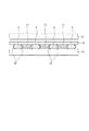
図2は、加硫成形用の金型11とそのキャビティ内にセットする弾性クローラ1の予備成形素材とを示す横断面図である。また、図3は、図2のA−A線断面図である。
図2に示すように、加硫成形用の金型11は上型12と下型13とからなり、上型12は下型13に対して図示しないプレス装置によって接離自在となっている。
[Elastic crawler preform material and its mold]
FIG. 2 is a cross-sectional view showing a
As shown in FIG. 2, the
上型12には、クローラ本体2の外周側部分(接地側部分)を成形するための上成形溝14が形成され、下型13には、クローラ本体2の内周側部分(非接地側部分)を成形するための下成形溝15が形成されている。従って、上型12を下型13に接合すると、上下の各成形溝14,15によってクローラ本体2の横断面形状に相当するキャビティが構成される。
上成形溝14と下成形溝15の帯幅方向中央部には、クローラ本体2の係合孔3を成形するための突部16,17が帯長手方向(図2の紙面貫通方向)に所定間隔おきに形成されている。
The
また、上成形溝14には、クローラ本体2にラグ8を成形するためのラグ用凹部18が帯長手方向に所定間隔おきに形成され、下成形溝15には、芯金4の係合突起7が嵌り込む芯金用凹部19が帯長手方向に所定間隔おきに形成されている。
クローラ本体2の予備成形素材は、クローラ本体2の接地側部分(図2の上側部分)を構成する未加硫の第1ゴム層21と、クローラ本体2の非接地側部分(図2の下側部分)を構成する未加硫の第2ゴム層22とからなる。
The
The preforming material of the
このうち、第1ゴム層21は、上成形溝14の内部に充填される上側スラグ23と、芯金4の翼部6の接地側に配置される左右一対の抗張体層24とからなる。各抗張体層24の断面内部には前記抗張体9が予め埋設されている。
なお、図2では図示していないが、上側スラグ23の上面側には、クローラ本体2の外周面に設けるラグ8を構成するための、未加硫ゴムよりなるラグ用ブロックが帯長手方向に所定間隔おきに配置される。
Among these, the
Although not shown in FIG. 2, on the upper surface side of the
第2ゴム層22は、下成形溝15の内部における芯金4の翼部6に対応する部分に充填される左右一対の下側スラグ25よりなる。
図3に示すように、帯長手方向(図3の左右方向)に並ぶ複数の芯金4の各翼部6は、抗張体層24と下側スラグ25の間に上下から挟まれるが、隣り合う芯金4の翼部6同士の間には、未加硫ゴムよりなる間詰めブロック27が介装されるようになっている。
The
As shown in FIG. 3, each
上記の予備成形素材のうち、下側スラグ25は、クローラ本体2の転輪通過面を構成することから、加硫成形後のゴム硬度が比較的高めの73〜80度になるように配合されたNR(天然ゴム)やSBR(スチレンブタジエンゴム)等よりなる。
これに対して、クローラ本体2の接地部側を構成する上側スラグ23は、下側スラグ25よりも加硫成形後のゴム硬度が小さくなるように配合されたNRやSBR等よりなり、例えば、建機用クローラの場合には65〜68度、コンバインの場合には62〜65度、雪上作業車の場合には58〜63度になるように配合される。
Among the above preformed materials, the
On the other hand, the
また、上側スラグ23と下側スラグ25の間に介在する間詰めブロック27及び後述の被覆材30の場合には、加硫成形後のゴム硬度が上側スラグ23と下側スラグ25の場合のほぼ中間となるように配合された、NRが主体のゴム材よりなり、具体的には60〜78度程度のゴム硬度となるように配合される。
In addition, in the case of the filling
〔芯金の被覆材〕
図4は、金型11に装着する前の被覆材30を有する芯金4の斜視図である。
図4に示すように、本実施形態では、金型11に装着する前の芯金4の翼部6の端縁面33,34が、未加硫ゴムよりなる被覆材30で予め被覆されている。
具体的には、この被覆材30は、翼部6の帯長手方向両端に位置する第1端縁面33を被覆する第1被覆部31と、翼部6の帯幅方向外端に位置する第2端縁面34を被覆する第2被覆部32とを一体に有する、細幅の未加硫ゴムシートよりなる。
[Core coating material]
FIG. 4 is a perspective view of the cored
As shown in FIG. 4, in this embodiment, the edge surfaces 33 and 34 of the wing |
Specifically, the covering
上記被覆材30は、帯長手方向両端に位置する一対の第1端縁面33と、帯幅方向外端に位置する第2端縁面34との双方に行き渡る長さを有しており、これらの端縁面33,34の縁長さ方向に沿って平面視コの字状に貼り付けられている。
また、被覆材30の貼り付け前の幅寸法b(図5(a)参照)は少なくとも芯金4の翼部6の厚さ寸法aよりも大きくなっており、図5(b)に示すように、貼り付け後において、翼部6の表裏両側に位置する双方のアール部6Rを含む範囲で端縁面33,34を被覆可能な寸法に設定されている。
The covering
Further, the width dimension b (see FIG. 5A) before the covering
なお、被覆材30で上記アール部6Rを被覆する理由は、後述の通り、このアール部6Rは、加硫成形時に未加硫ゴムが回り難い空隙37を形成する原因になる部分であることから、当該アール部6Rに行き渡るように被覆材30で被覆することが、端縁面33,34に対する加硫接着を強化する上で最も効果的だからである。
The reason why the rounded portion 6R is covered with the covering
〔弾性クローラの製造方法〕
上記構成の予備成形素材と芯金4を構成材料として弾性クローラ1を加硫成形するには、図2に示すように、下型13の下成形溝15の内部に左右一対の下側スラグ25,25を装填し、その各下側スラグ25,25の上に、予め被覆材30が貼り付けられた芯金4の翼部6及び間詰めブロック27をそれぞれ載置する。なお、この場合、芯金4の係合突起7は下成形溝15の芯金用凹部19に嵌め込むようにする。
[Method for producing elastic crawler]
In order to vulcanize and form the elastic crawler 1 using the preformed material and the cored
次に、芯金4の翼部6に対応する帯幅方向位置に、左右一対の抗張体層24,24を上から載置する。このとき、芯金4の両翼部6,6は、第1ゴム層21の抗張体層24と第2ゴム層22の下側スラグ25との間に上下から挟まれた状態となる。
そして、抗張体層24,24の上に上側スラグ23を載置してから、上型12を強制的にダウンさせて下型13に接合させる。これにより、クローラ本体2の予備成形素材が上成形溝14と下成形溝15とで構成されるキャビティ内で加圧され、その未加硫のゴム成分がキャビティ内を流動して所定形状に成形されることになる。
Next, the pair of left and right tensile body layers 24, 24 are placed from above on the band width direction position corresponding to the
Then, after placing the
その後、上記のように予備成形素材を加圧した状態で、図示しない加熱装置によって金型11を所定温度で所定時間だけ加熱することにより、金型11のキャビティ内の未加硫の各ゴム材に加硫反応を起こさせて予備成形素材を加硫成形する。
上記の加硫成形が完了すると、上型12を上昇させて下型13と分離し、完成品である弾性クローラ1を上型12及び下型13から脱型する。そして、脱型後の有端状の弾性クローラ1の帯長手方向端部同士を別工程にて互いに接合することにより、無端帯状の弾性クローラ1の製造が完了する。
Thereafter, in a state where the preforming material is pressurized as described above, the unvulcanized rubber material in the cavity of the
When the above vulcanization molding is completed, the
〔従来製法の問題点〕
図7(a)〜(c)は、芯金4に被覆材30を設けない従来製法の場合の、予備成形素材の積層状態を示す側面断面図(図2のA−A線断面図に相当する断面図)である。
図7(a)〜(c)のうち、図7(a)は間詰めブロック27がない場合を示す。
この場合、抗張体層24と下側スラグ25の間に翼部6の厚さ分の空間層36が形成されるので、この空間層36がすべて埋まる分の未加硫ゴムの塑性流動が抗張体層24や下側スラグ25において発生しなければ、加硫成形後のゴム材が翼部6の第1端縁面33に適切に加硫接着しない。
[Problems of conventional manufacturing methods]
7 (a) to 7 (c) are side cross-sectional views (corresponding to the cross-sectional view taken along the line AA in FIG. 2) showing the laminated state of the preformed material in the case of the conventional manufacturing method in which the
Of FIGS. 7A to 7C, FIG.
In this case, since the
これに対して、図7(b)のように、翼部6の間に間詰めブロック27を介装した場合には、空間層36の大部分が未加硫ゴムで満たされるので、図7(a)の場合に比べて、翼部6の第1端縁面33に対する加硫接着がより確実になる。
しかし、図7(b)の場合でも、翼部6の表裏両側にアール部6R(図5参照)がある場合には、間詰めブロック27と翼部6の間にほぼ三角形状の空隙37が形成されるので、加硫成形時における未加硫ゴムの塑性流動が不十分であると、加硫成形後にその空隙37が残存する恐れがある。
On the other hand, as shown in FIG. 7B, when the
However, even in the case of FIG. 7B, when there are rounded portions 6R (see FIG. 5) on both the front and back sides of the
また、図7(c)に示すように、間詰めブロック27の代わりに、未加硫ゴムよりなる帯長手方向に延びる帯状間詰め層38を、翼部6と下側スラグ25の上に敷くこともあるが、この場合も、帯状間詰め層38と翼部6の第1端縁面33の間にほぼ三角形状の空隙37が形成されるので、加硫成形時における未加硫ゴムの塑性流動が不十分な場合には、加硫成形後にその空隙37が残存する恐れがある。
Further, as shown in FIG. 7 (c), instead of the
このように、従来製法では、予備成形素材を金型11にセットした段階では、翼部6の第1端縁面33に面する空隙37を完全に埋めることができないので、加硫成形時における未加硫ゴムの流れ方によっては、芯金4の翼部6の第1端縁面33に対して未加硫ゴムが十分に回らず、第1縁端面33に対する接着力が不十分となったり、第1端縁面33に近接してエア溜まりが残存したりすることがある。
As described above, in the conventional manufacturing method, at the stage where the preforming material is set in the
〔本実施形態の効果〕
これに対して、本実施形態の製造方法によれば、芯金4の翼部6における帯長手方向両端に位置する第1縁端面33を、未加硫ゴムよりなる被覆材30で予め被覆しておき(図4参照)、その芯金4の翼部6を間に挟んだ状態で第1ゴム層21と第2ゴム層22を金型11のキャビティ内にセットするようにしたので、加硫成形を行う前に翼部6の第1端縁面33に対面する空隙が発生するのが防止される。
[Effect of this embodiment]
On the other hand, according to the manufacturing method of the present embodiment, the
従って、その後の加硫成形において、芯金4の翼部6の帯長手方向両端に位置する第1端縁面33にゴム材料を確実に加硫接着させることができるので、第1端縁面33からのゴム材料の剥離が効果的に抑制され、弾性クローラ1の耐久性を向上することができる。
また、本実施形態の製造方法によれば、被覆材30が、第1端縁面33に対応する第1被覆部31だけでなく、翼部6の帯幅方向外端に位置する第2端縁面34を被覆する第2被覆部32を有するので、第2端縁面34に対してもゴム材料を確実に加硫接着させることができる。従って、芯金4をより強固にクローラ本体2に一体化することができる。
Accordingly, in the subsequent vulcanization molding, the rubber material can be securely vulcanized and bonded to the
Further, according to the manufacturing method of the present embodiment, the covering
なお、上記被覆材30はその長さ方向において途中で分断していてもよい。もっとも、この場合には、分割された被覆材30をそれぞれ端縁面33,34に貼り付ける作業が繁雑になるし、加硫成形時において被覆材30が剥がれ易くなる。
従って、図5に示すように、翼部6の第1及び第2端縁面33,34の双方を連続的に被覆可能な長さの被覆材30を採用し、この被覆材30を、各端縁面33,34に沿って平面視コの字状に貼り付けることが好ましい。
In addition, the said coating | covering
Therefore, as shown in FIG. 5, a covering
〔その他の変形例〕
今回開示した実施形態は本発明の例示であって制限的なものではない。本発明の範囲は、上記実施形態ではなく特許請求の範囲によって示され、特許請求の範囲及びその構成と均等な範囲でのすべての変更が含まれる。
例えば、図6に示すように、第2縁端面34を被覆する第2被覆部32を省略し、帯長手方向両端に位置する第1端縁面33を被覆する第1被覆部31のみで、被覆材30を構成することにしてもよい。
[Other variations]
The embodiments disclosed herein are illustrative of the present invention and are not limiting. The scope of the present invention is shown not by the above-described embodiment but by the scope of claims for patent, and includes all modifications within the scope equivalent to the scope of claims and their configurations.
For example, as shown in FIG. 6, the
また、上記実施形態では、弾性クローラ1の接地側部分を上型12で成形し、非接地側部分を下型13で成形する金型11を使用したが、前記特許文献1のように、弾性クローラ1の帯幅方向一端側を成形する上型と他端側を成形する下型とからなる金型を用いる場合にも、本発明の製造方法を適用することができる。
Moreover, in the said embodiment, although the metal mold | die 11 which shape | molds the earthing | grounding side part of the elastic crawler 1 with the upper mold |
1 弾性クローラ
2 クローラ本体
4 芯金
5 厚肉部
6 翼部
6R アール部
7 係合突起
11 金型
12 上型
13 下型
21 第1ゴム層
22 第2ゴム層
30 被覆材
31 第1被覆部
32 第2被覆部
33 第1縁端面
34 第2縁端面
DESCRIPTION OF SYMBOLS 1
Claims (4)
前記芯金の翼部の帯長手方向両端に位置する第1端縁面を、未加硫ゴムよりなる被覆材で予め被覆する第1工程と、
前記クローラ本体の接地側部分を構成する未加硫の第1ゴム層と、前記クローラ本体の非接地側部分を構成する未加硫の第2ゴム層との間に前記翼部を挟んだ状態で、前記各ゴム層を金型のキャビティ内にセットする第2工程と、
前記キャビティ内の未加硫の各ゴム材を加圧下で加熱して加硫成形する第3工程と、 を含むことを特徴とする弾性クローラの製造方法。 A method of manufacturing an elastic crawler in which a plurality of core bars are provided at predetermined intervals in the longitudinal direction of the belt inside an endless belt-shaped rubber crawler body,
A first step of previously covering the first edge surfaces located at both ends in the longitudinal direction of the wing portion of the core metal with a coating material made of unvulcanized rubber;
A state in which the wing portion is sandwiched between an unvulcanized first rubber layer constituting the grounded side portion of the crawler body and an unvulcanized second rubber layer constituting the non-grounded side portion of the crawler body. And a second step of setting each rubber layer in the cavity of the mold,
A third step of heating and vulcanizing each unvulcanized rubber material in the cavity under pressure, and a method for producing an elastic crawler.
Priority Applications (1)
| Application Number | Priority Date | Filing Date | Title |
|---|---|---|---|
| JP2010285523A JP5613552B2 (en) | 2010-12-22 | 2010-12-22 | Method for producing elastic crawler |
Applications Claiming Priority (1)
| Application Number | Priority Date | Filing Date | Title |
|---|---|---|---|
| JP2010285523A JP5613552B2 (en) | 2010-12-22 | 2010-12-22 | Method for producing elastic crawler |
Publications (2)
| Publication Number | Publication Date |
|---|---|
| JP2012131386A JP2012131386A (en) | 2012-07-12 |
| JP5613552B2 true JP5613552B2 (en) | 2014-10-22 |
Family
ID=46647516
Family Applications (1)
| Application Number | Title | Priority Date | Filing Date |
|---|---|---|---|
| JP2010285523A Expired - Fee Related JP5613552B2 (en) | 2010-12-22 | 2010-12-22 | Method for producing elastic crawler |
Country Status (1)
| Country | Link |
|---|---|
| JP (1) | JP5613552B2 (en) |
Family Cites Families (5)
| Publication number | Priority date | Publication date | Assignee | Title |
|---|---|---|---|---|
| JP4338501B2 (en) * | 2003-11-18 | 2009-10-07 | 住友ゴム工業株式会社 | Method for producing elastic crawler |
| JP2006151193A (en) * | 2004-11-29 | 2006-06-15 | Bridgestone Corp | Rubber crawler |
| JP2006182152A (en) * | 2004-12-27 | 2006-07-13 | Sumitomo Rubber Ind Ltd | Rubber crawler |
| JP2009061830A (en) * | 2007-09-04 | 2009-03-26 | Bridgestone Corp | Rubber crawler |
| JP5210619B2 (en) * | 2007-12-19 | 2013-06-12 | 株式会社ブリヂストン | Rubber crawler manufacturing method |
-
2010
- 2010-12-22 JP JP2010285523A patent/JP5613552B2/en not_active Expired - Fee Related
Also Published As
| Publication number | Publication date |
|---|---|
| JP2012131386A (en) | 2012-07-12 |
Similar Documents
| Publication | Publication Date | Title |
|---|---|---|
| US20080136255A1 (en) | Endless track belt and method of making same | |
| JP6654709B2 (en) | Composite layer tire | |
| EP2817162B1 (en) | Projecting features molded within submerged tread voids | |
| US20070126286A1 (en) | Endless track belt | |
| WO2007145150A1 (en) | Precured tread and retreaded tire | |
| WO2007148800A1 (en) | Structure of rubber crawler track | |
| CN102958685A (en) | Thin plate for a lining of a mould intended for vulcanizing a tyre tread | |
| JP5613552B2 (en) | Method for producing elastic crawler | |
| JP2011195085A (en) | Core-less elastic crawler | |
| JPH085146B2 (en) | Rubber crawler manufacturing method | |
| JP5026206B2 (en) | Rubber crawler manufacturing method and mold for molding | |
| JP5210619B2 (en) | Rubber crawler manufacturing method | |
| JP5790213B2 (en) | Rehabilitated tire and manufacturing method thereof | |
| JP2010076309A (en) | Method for manufacturing rubber crawler | |
| JP5530342B2 (en) | Manufacturing method of tire with lug and tire | |
| US11370499B2 (en) | Crawler track, in particular rubber crawler track | |
| JP2000210948A (en) | Rubber crawler manufacturing method | |
| JP5628593B2 (en) | Precured tread and retreaded tire using precure tread | |
| JP2010076228A (en) | Method for manufacturing rubber crawler | |
| JPH06102435B2 (en) | Rubber crawler repair method and repaired rubber crawler | |
| JP4270938B2 (en) | Core rubber-free total rubber crawler | |
| CN108136845B (en) | Method for manufacturing a noise-reducing tread | |
| CA2568585A1 (en) | Improved endless track belt | |
| CN108136622B (en) | Moulding element for manufacturing a noise-reducing tread | |
| MX2015005076A (en) | Method of retreading a tire. |
Legal Events
| Date | Code | Title | Description |
|---|---|---|---|
| A621 | Written request for application examination |
Free format text: JAPANESE INTERMEDIATE CODE: A621 Effective date: 20131118 |
|
| A977 | Report on retrieval |
Free format text: JAPANESE INTERMEDIATE CODE: A971007 Effective date: 20140813 |
|
| TRDD | Decision of grant or rejection written | ||
| A01 | Written decision to grant a patent or to grant a registration (utility model) |
Free format text: JAPANESE INTERMEDIATE CODE: A01 Effective date: 20140819 |
|
| A61 | First payment of annual fees (during grant procedure) |
Free format text: JAPANESE INTERMEDIATE CODE: A61 Effective date: 20140908 |
|
| R150 | Certificate of patent or registration of utility model |
Ref document number: 5613552 Country of ref document: JP Free format text: JAPANESE INTERMEDIATE CODE: R150 |
|
| R250 | Receipt of annual fees |
Free format text: JAPANESE INTERMEDIATE CODE: R250 |
|
| LAPS | Cancellation because of no payment of annual fees |