JP5610074B2 - Transition mechanism of energy efficient mobile overlay network - Google Patents
Transition mechanism of energy efficient mobile overlay network Download PDFInfo
- Publication number
- JP5610074B2 JP5610074B2 JP2013517037A JP2013517037A JP5610074B2 JP 5610074 B2 JP5610074 B2 JP 5610074B2 JP 2013517037 A JP2013517037 A JP 2013517037A JP 2013517037 A JP2013517037 A JP 2013517037A JP 5610074 B2 JP5610074 B2 JP 5610074B2
- Authority
- JP
- Japan
- Prior art keywords
- state
- transition
- radio
- micro
- enb
- Prior art date
- Legal status (The legal status is an assumption and is not a legal conclusion. Google has not performed a legal analysis and makes no representation as to the accuracy of the status listed.)
- Expired - Fee Related
Links
Images


Classifications
-
- H—ELECTRICITY
- H04—ELECTRIC COMMUNICATION TECHNIQUE
- H04W—WIRELESS COMMUNICATION NETWORKS
- H04W72/00—Local resource management
- H04W72/04—Wireless resource allocation
-
- H—ELECTRICITY
- H04—ELECTRIC COMMUNICATION TECHNIQUE
- H04W—WIRELESS COMMUNICATION NETWORKS
- H04W24/00—Supervisory, monitoring or testing arrangements
- H04W24/02—Arrangements for optimising operational condition
-
- H—ELECTRICITY
- H04—ELECTRIC COMMUNICATION TECHNIQUE
- H04W—WIRELESS COMMUNICATION NETWORKS
- H04W36/00—Hand-off or reselection arrangements
- H04W36/16—Performing reselection for specific purposes
-
- H—ELECTRICITY
- H04—ELECTRIC COMMUNICATION TECHNIQUE
- H04W—WIRELESS COMMUNICATION NETWORKS
- H04W72/00—Local resource management
- H04W72/04—Wireless resource allocation
- H04W72/044—Wireless resource allocation based on the type of the allocated resource
- H04W72/0473—Wireless resource allocation based on the type of the allocated resource the resource being transmission power
-
- H—ELECTRICITY
- H04—ELECTRIC COMMUNICATION TECHNIQUE
- H04W—WIRELESS COMMUNICATION NETWORKS
- H04W16/00—Network planning, e.g. coverage or traffic planning tools; Network deployment, e.g. resource partitioning or cells structures
- H04W16/24—Cell structures
- H04W16/32—Hierarchical cell structures
-
- Y—GENERAL TAGGING OF NEW TECHNOLOGICAL DEVELOPMENTS; GENERAL TAGGING OF CROSS-SECTIONAL TECHNOLOGIES SPANNING OVER SEVERAL SECTIONS OF THE IPC; TECHNICAL SUBJECTS COVERED BY FORMER USPC CROSS-REFERENCE ART COLLECTIONS [XRACs] AND DIGESTS
- Y02—TECHNOLOGIES OR APPLICATIONS FOR MITIGATION OR ADAPTATION AGAINST CLIMATE CHANGE
- Y02D—CLIMATE CHANGE MITIGATION TECHNOLOGIES IN INFORMATION AND COMMUNICATION TECHNOLOGIES [ICT], I.E. INFORMATION AND COMMUNICATION TECHNOLOGIES AIMING AT THE REDUCTION OF THEIR OWN ENERGY USE
- Y02D30/00—Reducing energy consumption in communication networks
- Y02D30/70—Reducing energy consumption in communication networks in wireless communication networks
Description
本発明は、無線通信システムに関する。 The present invention relates to a wireless communication system.
本発明は、無線通信システムに関する。3GPP―LTE、WCDMA、802.16e−2005及び802.16mを含むシステムに基づくCDMA又はOFDMAのような無線ネットワークの計画は、主としてネットワークの地理的カバレッジ及び容量(データスループット)に基づく。高密度の加入者を有する領域、例えば密集した都市、都市又は郊外では、容量は、提供されるセル半径、したがってセルサイト密度の決定的要因になる場合が多い。したがって、単一の無線局(又は基地局又は中継局)により提供されるセル半径は、該無線局によりサポートできる実際の無線カバレッジよりも小さい可能性がある。しかしながら、一時的なトラフィック負荷の変動及び他の要因は、カバレッジに影響を与えずに、低トラフィック要求の時間中に幾つかの無線局をオフに切り替えることを可能にする。幾つかの無線局を周期的にオフに切り替えることは、全ての無線局が送信しているときに濃密なレイヤが、幾つかの無線局がオフに切り替えられているときに、例えば低無線サービス要求のときに希薄なレイヤが見えるので、オーバレイ技術又はスキームと称される。 The present invention relates to a wireless communication system. Planning for wireless networks such as CDMA or OFDMA based on systems including 3GPP-LTE, WCDMA, 802.16e-2005 and 802.16m is primarily based on the geographical coverage and capacity (data throughput) of the network. In areas with a high density of subscribers, such as dense cities, cities or suburbs, capacity is often a decisive factor for the provided cell radius and hence cell site density. Thus, the cell radius provided by a single radio station (or base station or relay station) may be smaller than the actual radio coverage that can be supported by the radio station. However, temporary traffic load fluctuations and other factors allow several radio stations to be switched off during times of low traffic demand without affecting coverage. Switching some radio stations off periodically means that the dense layer when all radio stations are transmitting, for example when low radio services are switched when some radio stations are switched off. Because a sparse layer is visible when requested, it is referred to as an overlay technique or scheme.
このようなオーバレイスキームをサポートするよう計画されたネットワークは、電力消費の節約をもたらし、それによりカーボンフットプリントや事業者の運営費(OPEX)の削減をもたらす。よって、オーバレイネットワーク技術は、節電の目的でモバイルブロードバンド業界で広く提案され議論されている。事業者に利用可能なリソースに依存して多数の異なる構成を実施することが可能である。このような構成の一例を図1に示す。図は、2つの異なる状態にあるネットワーク1を示す。左は、低容量状態を示す。この低容量状態は、左側の時間図に示したハイライトした時間において実施され、幾つかの無線局2のみがアクティブになり、より大きいセル3を生じる。アクティブな無線局2の各々は、セル3を生じる。図中、アクティブな無線局は、非アクティブな無線局4よりも大きく示される。高要求の時間には、ネットワークは対応する時間図と共に右に示す高容量状態に切り替えられ、セルサイズが縮小される。全ての無線局2、4がアクティブであり、全て同じサイズを有するよう示され、セル3を生じている。2つの状態間の遷移で、セルサイズは、本例では1000mから433mに縮小する。
Networks planned to support such overlay schemes will result in power savings, thereby reducing the carbon footprint and operator operating costs (OPEX). Therefore, overlay network technology is widely proposed and discussed in the mobile broadband industry for the purpose of power saving. Many different configurations can be implemented depending on the resources available to the operator. An example of such a configuration is shown in FIG. The figure shows the
図1の例示的なシナリオは、時間図に示すように、24時間の期間に渡るトラフィック要求が1日のうちの12時間では所与の閾を超えるが残りの12時間の期間では閾より低い場合を考慮している。上述のような容量の制約された展開では、トラフィックが特定の閾より低くなる期間中にトラフィック要求を満たしたまま、カバレッジに影響を与えずに特定の無線局をオフに切り替えることが可能である。対比を目的として、両状態でオンのままである無線局を「マクロ」無線局と称し、高容量状態(高いトラフィック要求の間)のみオンのままである無線局をマイクロ無線局と称する。したがって、オーバレイネットワークの2つのティア(又はレイヤ)が形成される。高容量状態では全ての無線局がオンであり、低容量状態ではマクロ無線局のみがオンである。 The exemplary scenario of FIG. 1 shows that the traffic request over a 24-hour period exceeds a given threshold for 12 hours of the day but is lower than the threshold for the remaining 12-hour period, as shown in the time diagram. Consider the case. In capacity-constrained deployments such as those described above, it is possible to switch off a particular radio station without affecting the coverage while meeting traffic requirements during periods when traffic falls below a certain threshold. . For comparison purposes, a radio station that remains on in both states is referred to as a “macro” radio station, and a radio station that remains on only in a high capacity state (during high traffic requests) is referred to as a micro radio station. Thus, two tiers (or layers) of the overlay network are formed. All radio stations are on in the high capacity state, and only the macro radio station is on in the low capacity state.
留意すべき点は、本例では、図1のマクロ無線局のカバレッジが、マイクロ無線局がオンのままの間はマイクロ無線局のカバレッジと同様だが、マイクロ無線局がオフに切り替えられたときにはネットワーク全体のカバレッジを維持するために増大することである。 It should be noted that in this example, the coverage of the macro radio station of FIG. 1 is similar to the coverage of the micro radio station while the micro radio station remains on, but when the micro radio station is switched off, the network Increase to maintain the overall coverage.
R3-092787, Huawei, ZTE, China Unicom, “Discussion on Gradually Cell Switch off/on”, 3GPP TSG-RAN WG3#65bis, October 2009は、オーバレイスキームに関し、セルがオフに切り替えられる段階の間の遷移では、遷移中のユーザ機器のセル間ハンドオーバを制御するために、送信電力を引き上げる又は引き下げるという概念を提供している。しかしながら、発明者等は、遷移の実際の実装が、セルをオン又はオフに切り替える電力パラメータの制御された調整より多くの入力を必要とすることを理解した。 R3-092787, Huawei, ZTE, China Unicom, “Discussion on Gradually Cell Switch off / on”, 3GPP TSG-RAN WG3 # 65bis, October 2009, for overlay schemes, The concept of increasing or decreasing the transmission power is provided in order to control the inter-cell handover of the user equipment in transition. However, the inventors have realized that the actual implementation of the transition requires more input than the controlled adjustment of the power parameter to switch the cell on or off.
本発明は、エネルギ効率の良いモバイルオーバレイネットワークの遷移メカニズムを提供する。 The present invention provides an energy efficient mobile overlay network transition mechanism.
本発明の実施形態は、第1の数の無線局がアクティブな第1の状態と第2の別の数の無線局がアクティブな第2の状態との間の切り替えを有する通信ネットワーク内のセルのクラスタにおける自動状態遷移の方法を提供する。当該方法は、前記第2の状態は、前記第1の状態と同じ地理的カバレッジだが異なる容量を提供することを目的とし、状態間の遷移は送信パラメータ調整を用いて実行され、前記送信パラメータ調整は複数の無線局で行われ、該無線局に対して時間的に協調される。 Embodiments of the invention include a cell in a communication network having a switch between a first state in which a first number of radio stations are active and a second state in which a second other number of radio stations are active. Provides a method for automatic state transitions in multiple clusters. The method aims at the second state providing the same geographical coverage but different capacity as the first state, the transition between states being performed using transmission parameter adjustment, wherein the transmission parameter adjustment Is performed at a plurality of radio stations and is coordinated in time with respect to the radio stations.
省エネルギオーバレイネットワークの実際の実装の主な特徴は、セルのクラスタ(又はグループ)内の1又は複数の無線局(一般的に等価な用語により、無線基地局、基地局、BS又はeNBとも称されるが、中継局も含む)がオン又はオフに切り替えられる遷移である。発明者は、遷移において、1つより多い無線局がその送信パラメータを調整すべきこと、及び無線局における調整が協調されるべきこと、例えば協調ステップが複数の無線局で行われるようにすること(しかしながら各ステップは1つの無線局のみで行われても良い)を理解している。例えば、少なくともクラスタ内の、オン又はオフに切り替えている無線局の近隣の無線局は、切り替えと協調してそれら自身の無線パラメータを適応させなければならない。 The main feature of an actual implementation of an energy saving overlay network is one or more radio stations (generally termed radio base stations, base stations, BSs or eNBs in a cluster (or group) of cells. (Including relay stations) are switched on or off. The inventor ensures that at the transition, more than one radio station should adjust its transmission parameters and that the adjustments at the radio stations should be coordinated, e.g. a coordination step is performed at multiple radio stations. (However, each step may be performed by only one radio station). For example, at least wireless stations in the cluster that are switching on or off, must adapt their own wireless parameters in coordination with the switching.
遷移中、ネットワーク内の無線伝搬特性は変化し、これはクラスタ内のユーザ機器(UE)に無線リンク障害又は呼のドロップを生じる可能性がある。さらに、遷移は利用可能な無線局の数の変化を有するので、アクティブUEの移動状態(移動状態は多くの他の状況でハンドオーバをトリガする)に関係なく、クラスタ内のハンドオーバ(HO)アクティビティに望ましくない制御されないサージをもたらし得る。以上に鑑み、発明者は、無線局の協調が有利であることに気付いた。したがって、無線局における送信パラメータ調整の特定の相対タイミングが定められる。この協調は、無線リンクが遷移中に維持されること、遷移中にマイクロからマクロ無線局へ又はその逆に移動している全てのUEに対してハンドオーバが成功することを保証することを目的としている。 During the transition, the radio propagation characteristics in the network change, which can cause radio link failure or call drop to user equipment (UE) in the cluster. In addition, since the transition has a change in the number of available radio stations, regardless of the active UE's mobility state (the mobility state triggers handover in many other situations), the handover (HO) activity in the cluster It can result in undesirable uncontrolled surges. In view of the above, the inventor has realized that the cooperation of radio stations is advantageous. Therefore, specific relative timing of transmission parameter adjustment in the radio station is determined. This cooperation aims to ensure that the radio link is maintained during the transition and that the handover is successful for all UEs moving from the micro to the macro radio station or vice versa during the transition. Yes.
本発明の実施形態は、遷移メカニズムのためのソリューションを提供する。該ソリューションは、クラスタ内のオフからオンへの(低状態から高状態への)又はオンからオフへの(高状態から低状態への)遷移に対する自動及び協調パラメータ調整を含み、UEによりeNBへ報告がカバレッジを失わず又は無線リンク障害(Radio Link Failure:RLF)を経験しないこと、及びUEがHOに関連するRLF又はRACH衝突を経験することなく円滑なハンドオーバを実行することを目的とする。これらは以下に詳細に説明される。 Embodiments of the present invention provide a solution for the transition mechanism. The solution includes automatic and coordinated parameter adjustments for off-to-on (low-to-high) or on-to-off (high-to-low) transitions in the cluster and to the eNB by the UE It is intended that the reports do not lose coverage or experience Radio Link Failure (RLF) and perform a smooth handover without the UE experiencing RLF or RACH collisions associated with HO. These are described in detail below.
本発明の実施形態の好適な特徴は、単なる例として添付の図面を参照して以下に説明される。
<定義>
用語「クラスタ」は、ここでは、この本願明細書で議論される状態遷移の目的で集合的に及び望ましくは独立して検討されるネットワーク内の少なくとも2つの無線局のグループを有する。したがって、最も単純な実施形態では、2つの無線局を含むクラスタが提供され、一方の無線局はオフに切り替えられ、他方は2状態の間の調整された遷移において自身の無線パラメータを適応する。
<Definition>
The term “cluster” here has a group of at least two radio stations in the network that are considered collectively and preferably independently for the purposes of the state transitions discussed herein. Thus, in the simplest embodiment, a cluster comprising two radio stations is provided, one radio station being switched off and the other adapting its radio parameters in a coordinated transition between the two states.
専門的な読者は、2つの状態間の地理的カバレッジに幾つかの軽微な変更が存在し得ること、しかし2つの状態間の主要な変化は、所与の地理的領域、したがってUE通信をサポートする能力において多数のアクティブな無線局に存在することを理解するだろう。本願明細書で言及されるUEは、モバイル又は固定電話、PDA、ラップトップコンピュータ及び/又は無線リンクを介してセルを提供する無線局により供される他の装置であり得る。 Expert readers may notice that there may be some minor changes in the geographic coverage between the two states, but the major changes between the two states support a given geographic region and thus UE communication It will be appreciated that there are many active radio stations in the ability to do. A UE as referred to herein may be a mobile or landline phone, PDA, laptop computer and / or other device served by a radio station providing a cell via a radio link.
2つの状態間の遷移は、送信パラメータが調整される1又は複数の個々の協調ステップを有し得る。遷移中の協調ステップの数は、遷移により生成されることが期待されるUEハンドオーバの期待数により決定され得る。したがって、ハンドオーバの数が利用可能なアップリンク/ダウンリンク(UL/DL)により処理される程十分低いと期待される場合、送信パラメータを調整する際の協調ステップの数は、理論的には1まで減少され得る。高容量状態への遷移では、この単一のステップは、幾つかの無線局における協調送信パラメータを調整する一部として、オンに切り替えられる少なくとも1つの無線局が関与する。或いは、無線局をオンに切り替える特定のステップは、協調されなくても良い(例えば、何からかの理由で、UEハンドオーバを生じない場合)。低容量状態への遷移では、少なくとも1つの無線局がオフに切り替えられる。オンに切り替える遷移とは対照的に、オフへの切り替えは、協調されない可能性がある。大多数の例では、オフへの切り替えは、協調パラメータ調整の1又は複数のステップの後に行われ、オフに切り替えられる無線局に属する全てのUEが事前にハンドオーバできるようにする。 A transition between two states may have one or more individual coordination steps in which transmission parameters are adjusted. The number of coordination steps in transition may be determined by the expected number of UE handovers that are expected to be generated by the transition. Thus, if the number of handovers is expected to be low enough to be handled by the available uplink / downlink (UL / DL), the number of coordination steps in adjusting the transmission parameters is theoretically 1 Can be reduced. In the transition to the high capacity state, this single step involves at least one radio station that is switched on as part of adjusting the coordinated transmission parameters at several radio stations. Alternatively, the particular step of turning on the radio station may not be coordinated (eg, if for some reason a UE handover does not occur). In the transition to the low capacity state, at least one radio station is switched off. In contrast to transitions that switch on, switching off may not be coordinated. In the majority of examples, switching off takes place after one or more steps of coordination parameter adjustment, so that all UEs belonging to radio stations to be switched off can be handed over in advance.
遷移における各ステップは、カバレッジ調整量の点で他と同じサイズであり得るが、最後のオフに切り替えるステップ又は最初のオンに切り替えるステップを除いて良い。(上述のような)別個のオフへの切り替えステップは、オフに切り替えている基地局に依然として属しているUEの強制ハンドオーバにより進められ得る。したがって、オフへの切り替えは、必ずしも無線局間で協調されない低容量状態への遷移で唯一のステップであり得る。しかしながら、上述のように、オンへの切り替えステップは、恐らく、直ちにUEハンドオーバをトリガし、協調される可能性が高い。 Each step in the transition may be the same size as the others in terms of coverage adjustment, but may exclude the last step of switching off or the first step of switching on. A separate switch-off step (as described above) may proceed with a forced handover of UEs still belonging to the base station switching off. Thus, switching off may be the only step in the transition to a low capacity state that is not necessarily coordinated between radio stations. However, as mentioned above, the switch-on step probably triggers a UE handover immediately and is likely to be coordinated.
影響を受けるリング内のアクティブなUEの数が非常に小さい場合(UE分布プロファイルにより決定され、以下に詳細に議論される)、所与のステップは他のステップより遙かに大きい。これは、アクティブなUEの数に対する処理を適応することにより、より速い状態遷移を可能にするという利点を有する。 If the number of active UEs in the affected ring is very small (determined by the UE distribution profile and discussed in detail below), a given step is much larger than the other steps. This has the advantage of allowing faster state transitions by adapting the processing for the number of active UEs.
ステップの(時間)間隔は、所与のステップで、全てのアクティブモードUEがハンドオーバ手順を完了するのに必要な予測時間に基づき定められ得る。しかしながら、ステップサイズは期待されるハンドオーバ数を制限するよう制御されるので、ステップ間隔は、実際には異なるステップ間で一定で良い。 The step (time) interval may be determined based on the expected time required for all active mode UEs to complete the handover procedure at a given step. However, since the step size is controlled to limit the expected number of handovers, the step interval may actually be constant between different steps.
所望のステップ間隔を達成するために、望ましくは少なくとも1ステップの遷移パラメータ調整の後に、時間遅延「t」が続く。この遅延は、オフに切り替えるステップを除き、各ステップに提供され得る。このように、時間遅延は、次のステップが行われる前に期待されるUEハンドオーバのために十分なハンドオーバ時間を可能にするために用いることができるので、非常に有利である。発明者は、このような時間同期無しに、無線カバレッジが期待通り又は計画通りに変化せず、したがってUEの無線リンク障害(Radio Link Failure)を生じる可能性があり、QoSに影響を与え得ることを理解した。 To achieve the desired step interval, preferably at least one step of transition parameter adjustment is followed by a time delay “t”. This delay can be provided for each step except for switching off. Thus, the time delay is very advantageous as it can be used to allow sufficient handover time for the expected UE handover before the next step takes place. Without such time synchronization, the inventor may not change radio coverage as expected or as planned, and thus may cause UE Radio Link Failure, which may affect QoS. Understood.
「t」の値は、一定であるか、実施される各ステップに対して個々に設定されても良く、望ましくは期待される又はステップ変化の結果として開始される全てのハンドオーバのためのハンドオーバ処理を完了するのに必要な合計時間より大きいか若しくはそれに等しい。例えば、3GPP−LTEの場合には、ハンドオーバ処理は、S1又はX2インタフェースを介して各UEについて生じ得る。「t」は、HOのための測定を報告するHOイベントからの時間、Time to Trigger、HO Command&Acknowledgement、Target eNBへのStatus/Resource転送、及び最後にSource eNBでリソースが解放されるまでの時間を有し得る。 The value of “t” may be constant or may be set individually for each step performed, preferably the handover process for all handovers that are expected or initiated as a result of a step change. Is greater than or equal to the total time required to complete For example, in the case of 3GPP-LTE, handover processing may occur for each UE via the S1 or X2 interface. “T” is the time from HO event reporting measurement for HO, Time to Trigger, HO Command & Acknowledgment, Status / Resource transfer to Target eNB, and finally time until resource is released in Source eNB Can have.
各ステップで調整され得る送信パラメータは、送信電力、アンテナダウンチルト(単にチルト又はアンテナチルトとも称される)、パワーオン/オフ、及びアンテナ高さ及びアンテナ方位角のような他の適切な送信パラメータを有する。これらの内の最後の2つは、以下の理由から詳細に検討されない。
(1)高さ及び/又は方位角は遠隔に調整できない。ソフトウェアコマンド(又は電気信号)がモータを作動できる(線形又は角度に関する機械的動きを生じる)としても、可動部分が故障する可能性が高く、それらの調整は常に推奨されない。
(2)現在、アンテナの高さも方位角も、状態間の遷移では十分であり、両者とも電力及び/又はチルト調整と一緒に実行される必要がない。
Transmission parameters that can be adjusted at each step are transmission power, antenna downtilt (also referred to simply as tilt or antenna tilt), power on / off, and other suitable transmission parameters such as antenna height and antenna azimuth. Have The last two of these are not discussed in detail for the following reasons.
(1) Height and / or azimuth cannot be adjusted remotely. Even if software commands (or electrical signals) can operate the motor (resulting in linear or angular mechanical movement), the moving parts are likely to fail and their adjustment is not always recommended.
(2) Currently, both the height and azimuth of the antenna are sufficient for transitions between states, and both need not be performed together with power and / or tilt adjustment.
多くの実施形態では、送信電力及びアンテナダウンチルトの両方が調整される。無線局でこれら2つのパラメータを同時に(つまり、単一のステップで)調整することは可能だが、これは、カバレッジに与える可能性のある全体的な影響により(制御されないハンドオーバをトリガする可能性がある)、通常不利である。したがって、望ましくは、送信電力及びチルトは、望ましくは上述のような遅延により分けられた、送信パラメータ調整の連続するステップで調整される。送信電力及びアンテナチルトは、どちらの順序で調整されても良い。 In many embodiments, both transmit power and antenna downtilt are adjusted. It is possible for a radio station to adjust these two parameters simultaneously (ie, in a single step), but this may trigger an uncontrolled handover due to the overall impact that it may have on coverage. Usually) is disadvantageous. Therefore, preferably the transmission power and tilt are adjusted in successive steps of transmission parameter adjustment, preferably divided by the delay as described above. The transmission power and the antenna tilt may be adjusted in either order.
本発明の実施形態は、2つより多くの状態(又はレイヤ)間を切り替え可能な通信ネットワークのクラスタに拡張できる。これにより、全ての無線局は、最高状態(最も高い容量要求を有する状態)でアクティブであり、より低い状態では無線局サイトの密度は低減する。これは、トラフィック要求の変化に関してネットワーク構成を適応するより高い柔軟性を可能にすることにより、エネルギ節約の更なる最適化を提供できる可能性がある。したがって、本発明の実施形態による方法は、第2の状態と第3の状態の間で切り替えるステップを有し、第3の状態では、更に異なる数の無線局がアクティブである。第3の状態は、第1及び第2の状態と同じ地理的カバレッジだが異なる容量を提供することを目的とする。第2の状態と第3の状態の間の遷移は、再び、送信パラメータ調整を用いて実行され、複数の無線局で行われ、これら全ての無線局について時間的に協調される。専門的な読者は、如何なる2状態間の切り替えも、第1及び第2の状態間の切り替えと同様に行われることを理解するだろう。 Embodiments of the present invention can be extended to clusters of communication networks that can switch between more than two states (or layers). This ensures that all radio stations are active at the highest state (the state with the highest capacity requirement), and at lower states the density of the radio station sites is reduced. This may provide further optimization of energy savings by allowing greater flexibility to adapt the network configuration with respect to changing traffic demands. Thus, the method according to an embodiment of the invention comprises the step of switching between a second state and a third state, in which a further different number of radio stations are active. The third state aims to provide the same geographic coverage but different capacity as the first and second states. The transition between the second state and the third state is again performed using transmission parameter adjustment, is performed at a plurality of radio stations, and is coordinated in time for all these radio stations. The expert reader will understand that switching between any two states is done in the same way as switching between the first and second states.
容量の昇順/降順で検討され得る2つより多い状態が存在する場合、連続的でない状態間の切り替えを行うことも可能である。つまり、m>1のとき、「n」から「n+m」へ又は「n」から「n−m」への状態変化が可能である。このような変化は、トラフィック負荷により決定でき、トラフィック負荷(容量要求)の変化が緩やかでなく急激なときに生じ得る。 If there are more than two states that can be considered in ascending / descending order of capacity, it is also possible to switch between non-continuous states. That is, when m> 1, a state change from “n” to “n + m” or from “n” to “nm” is possible. Such a change can be determined by the traffic load, and can occur when the change in the traffic load (capacity requirement) is not slow but rapid.
上述のように、状態間の遷移では、両状態でオンのままである無線局を「マクロ」無線局と称し、高容量状態(高いトラフィック要求の間)のみオンのままである無線局をマイクロ無線局と称する。高容量状態を「マイクロモード」と称し(マイクロ無線局がアクティブであるため)、低容量状態をマクロモードと称する(マクロ無線局のみがアクティブであるため)。以下の説明は、各クラスタ内の複数のマクロ無線局及び複数のマイクロ無線局に関する。しかし、専門的な読者は、実際には単一のマクロ無線局と単一のマイクロ無線局がクラスタ内にあっても良いことを理解するだろう。唯一の要件は、少なくとも1つのマイクロ無線局と少なくとも1つのマクロ無線局がクラスタ内にあれば良いことである。 As described above, in transitions between states, radio stations that remain on in both states are referred to as “macro” radio stations, and radio stations that remain on only in high capacity states (during high traffic requests) are micro It is called a radio station. The high capacity state is referred to as “micro mode” (because the micro radio station is active), and the low capacity state is referred to as macro mode (since only the macro radio station is active). The following description relates to a plurality of macro radio stations and a plurality of micro radio stations in each cluster. However, professional readers will understand that a single macro radio station and a single micro radio station may actually be in the cluster. The only requirement is that at least one micro radio station and at least one macro radio station need be in the cluster.
したがって、LTE用語を用いると、所与のeNBは、状態n(最も高い容量の状態)及び状態n−1でマクロeNBとして動作するが、状態n−2ではマイクロeNBになる。これは、状態が減ると、クラスタ内のアクティブなeNBの数も減るからである。このマクロ無線局としての動作からマイクロ無線局としての動作への切り替えは、クラスタ内の無線局毎に全ての状態について定められたパラメータにより決定される。望ましくは、パラメータの値は、クラスタ内の無線局毎に独立に定めることができ、eNB(又は別の用語では無線局)が切り替えによる影響を受けないように、つまり特定の遷移の間にマクロ又はマイクロ無線局としても動作しないようにすることが可能である。 Thus, using LTE terminology, a given eNB operates as a macro eNB in state n (highest capacity state) and state n-1, but becomes a micro eNB in state n-2. This is because as the state decreases, the number of active eNBs in the cluster also decreases. The switching from the operation as the macro radio station to the operation as the micro radio station is determined by parameters defined for all states for each radio station in the cluster. Desirably, the value of the parameter can be determined independently for each radio station in the cluster, so that the eNB (or radio station in other terms) is not affected by switching, i.e., during a particular transition Alternatively, it is possible not to operate as a micro radio station.
好都合なことに、クラスタ内の全てのマクロ無線局は、自身の送信パラメータを一緒に(少なくとも1ステップで)調整し、全てのマイクロ無線局は自身の送信パラメータを一緒に(少なくとも1ステップで)調整する。したがって、調整は並列であり、少なくとも実質的に同時である。上述の時間遅延は、関与する無線局間で調整を実際に同期するのを保証するのを助けるために用いることができる。多くの実施形態では、最後のオン/オフへの切り替えステップを含む各送信パラメータ調整ステップは、各種類の無線局により一緒に実行される。 Conveniently, all macro radio stations in the cluster adjust their transmission parameters together (in at least one step), and all micro radio stations adjust their transmission parameters together (in at least one step). adjust. Thus, the adjustments are parallel and at least substantially simultaneous. The time delay described above can be used to help ensure that the adjustments are actually synchronized between participating wireless stations. In many embodiments, each transmission parameter adjustment step, including the last on / off switching step, is performed together by each type of radio station.
幾つかの好適な実施形態では、2状態間の遷移のための送信パラメータ調整は、連続的な協調された段階で実行され、第1の段階は、各(1より多く存在する場合)マイクロ無線局又はマクロ無線局の全ての送信パラメータ調整のためであり、第2の段階は、各マクロ無線局又はマイクロ無線局の全ての送信パラメータ調整のためである。望ましくは、より高い要求状態への切り替えでは、各マイクロ無線局の送信が第1の段階で調整され、より低い要求状態への切り替えでは、各マクロ無線局の送信が第1の段階で調整される。これは、遷移中にUEが転送する無線局の容量が最初に増大することを可能にする。さらに、これは、カバレッジの変化により無線リンク障害が発生し得る前に、遷移中に、UEハンドオーバを完了させることを可能にする。 In some preferred embodiments, transmission parameter adjustments for transitions between two states are performed in a continuous coordinated phase, with the first phase being for each (if more than one) micro radio. The second stage is for adjusting all transmission parameters of each macro radio station or micro radio station. Desirably, transmission to each micro radio station is adjusted in a first stage for switching to a higher request state, and transmission to each macro radio station is adjusted in a first stage for switching to a lower request state. The This allows the capacity of the radio station that the UE transfers during the transition to increase initially. Furthermore, this allows the UE handover to be completed during the transition before a radio link failure can occur due to a change in coverage.
他の好適な実施形態では、マクロ及びマイクロ無線局は、自身の送信パラメータを一緒に調整する。例えば、両方の種類の無線局は、先ず送信電力を(例えば、1又は複数のステップで)調整し、次にアンテナチルトを(再び1又は複数のステップで)調整する。上述の時間遅延は、関与する無線局間で調整を実際に同期するのを保証するために用いることができる。 In other preferred embodiments, the macro and micro radio stations adjust their transmission parameters together. For example, both types of radio stations first adjust the transmit power (eg, in one or more steps) and then adjust the antenna tilt (again in one or more steps). The time delay described above can be used to ensure that the adjustment is actually synchronized between the participating radio stations.
望ましくは、クラスタは、協調サーバ又は望ましくは所与の時間に無線局の送信パラメータを調整するよう無線局にシグナリングすることにより、遷移中にクラスタ内の無線局の切り替え動作を協調する他の協調エンティティへのアクセスを有する。このシグナリングの開始は、トリガに応答しても良い。協調サーバは、一部の又は全部の無線局からUE分布プロファイル(後に詳述する)を要求しても良く、無線局にステップ間隔を指示しても良い。 Preferably, the cluster cooperates with the coordination server or other coordination to coordinate the switching operation of the radio stations in the cluster during the transition, preferably by signaling the radio station to adjust the transmission parameters of the radio station at a given time. Has access to the entity. This initiation of signaling may be in response to a trigger. The cooperation server may request a UE distribution profile (described later in detail) from some or all of the radio stations, and may instruct the radio stations for the step interval.
方法は、トラフィック負荷又はトラフィック要求が特定の閾と交差することにより、又は他の適切なトリガにより開始されても良い。望ましくは、方法は、遷移処理を取り消すことにより任意の時点で中止されても良い。この動作は、例えばトリガが無効になった場合に適する。例えば、トラフィック負荷又はトラフィック要求は、遷移処理中に特定の閾を逆方向に横切り得る。このような中止の可能性の利点は、誤ったトリガの場合に応答時間を最小化できることである。これは、方法が更なる調整を行う前に行うことができれば、最適に実施できる。遷移処理の取り消しは、中止までに行われた動作の逆の動作を、望ましくは逆の順序で実行するステップを含む。 The method may be initiated by traffic load or traffic demand crossing a certain threshold or by other suitable triggers. Desirably, the method may be aborted at any point in time by canceling the transition process. This operation is suitable, for example, when the trigger is disabled. For example, a traffic load or traffic request may cross a particular threshold in the reverse direction during the transition process. The advantage of such an abort possibility is that the response time can be minimized in the event of a false trigger. This can be done optimally if the method can be done before making further adjustments. Canceling the transition process includes a step of performing the reverse operation of the operation performed up to the cancellation, preferably in the reverse order.
本発明の更なる態様の実施形態は、第1の数の無線局がアクティブな第1の状態と第2の別の数の無線局がアクティブな第2の状態との間で切り替えられる無線局のクラスタを含む通信ネットワークに関する。第2の状態は、第1の状態と同じ地理的カバレッジだが異なる容量を提供することを目的とし、無線局は、送信パラメータ調整を用いて状態間の遷移を実行するよう動作可能であり、送信パラメータ調整は、複数の無線局で行われ、該無線局に対して時間的に協調される。 An embodiment of a further aspect of the invention is a radio station that is switched between a first state in which a first number of radio stations are active and a second state in which a second other number of radio stations are active. The present invention relates to a communication network including a cluster. The second state is intended to provide the same geographical coverage but different capacity as the first state, and the radio station is operable to perform transitions between states using transmission parameter adjustments and transmit The parameter adjustment is performed in a plurality of radio stations, and is coordinated in time with respect to the radio stations.
本発明の更に別の態様の実施形態は、通信ネットワーク内の無線局のクラスタ内の無線局に関する。クラスタは、第1の数の無線局がアクティブな第1の状態と第2の別の数の無線局がアクティブな第2の状態との間で切り替えるよう動作可能であり、第2の状態は、第1の状態と同じ地理的カバレッジだが異なる容量を提供することを目的とし、無線局は、送信パラメータ調整を用いて状態間の遷移を実行する制御機能を有し、送信パラメータ調整がクラスタ内の他の無線局と協調して行われるよう時間指定される。クラスタは、望ましくは無線局の送信パラメータを調整するよう無線局にシグナリングすることにより、遷移中にクラスタ内の全ての無線局の動作を協調する協調エンティティを有しても良い。無線局は、マイクロ無線局として又はマクロ無線局として又はその両方として(上述のように異なる状態遷移において)動作できる。 Yet another aspect of the invention relates to a wireless station in a cluster of wireless stations in a communication network. The cluster is operable to switch between a first state in which a first number of radio stations are active and a second state in which a second different number of radio stations are active, where the second state is In order to provide the same geographical coverage but different capacity as the first state, the radio station has a control function to perform transitions between states using transmission parameter adjustment, and the transmission parameter adjustment is within the cluster Time is specified to be performed in cooperation with other radio stations. The cluster may have a cooperating entity that coordinates the operation of all radio stations in the cluster during the transition, preferably by signaling the radio station to adjust the transmission parameters of the radio station. A radio station can operate as a micro radio station or as a macro radio station or both (in different state transitions as described above).
本発明の更なる態様の実施形態は、第1の数の無線局がアクティブな第1の状態と第2の別の数の無線局がアクティブな第2の状態との間の切り替えを協調することにより、通信ネットワークの無線局のクラスタにおける遷移を制御するよう動作可能な協調エンティティに関する。第2の状態は、第1の状態と同じ地理的カバレッジだが異なる容量を提供することを目的とし、協調エンティティは、無線局に送信パラメータ調整を用いて状態間の遷移を実行するよう指示する機能を有し、指示された送信パラメータ調整は、複数の無線局で行われ、該無線局に対して時間的に協調される。 An embodiment of a further aspect of the present invention coordinates switching between a first state in which a first number of radio stations are active and a second state in which a second other number of radio stations are active. In particular, it relates to a cooperating entity operable to control transitions in a cluster of radio stations in a communication network. The second state is intended to provide the same geographic coverage but different capacity as the first state, and the coordinating entity instructs the radio station to perform transitions between states using transmission parameter adjustments The instructed transmission parameter adjustment is performed by a plurality of radio stations, and is coordinated in time with respect to the radio stations.
協調エンティティは、メモリと、例えば遷移の起動の閾を横切ったか否かを計算するために用いられる計算機(プロセッサ)とを有し得る。協調エンティティは、任意的に、無線局から(各無線局のトラフィックアクティビティ及び各無線局により供されているアクティブなUEの地理的分布のような)データを受信する受信機と、(ネットワーク内の無線局の位置に従って)無線局に命令を供給する送信機と、を有する。計算機は、各無線局により供されているアクティブなUEの地理的分布が入手できる場合にはこの地理的分布を用いて、無線局へステップパラメータを送信するために、ステップサイズ及びステップ毎の時間遅延を決定する。 A cooperating entity may have a memory and a computer (processor) that is used to calculate, for example, whether or not a threshold of transition initiation has been crossed. The cooperating entity optionally has receivers (such as the traffic activity of each radio station and the geographical distribution of active UEs served by each radio station) from the radio stations (within the network). A transmitter for supplying instructions to the radio station (according to the position of the radio station) The calculator uses the geographical distribution of active UEs served by each radio station, if available, to send the step parameters to the radio station using the step size and the time per step. Determine the delay.
上述の態様のうちのいずれか及び全部の特徴及び望ましい特徴は結合されても良い。 Any and all features and desirable features of the above aspects may be combined.
本発明の実施形態によると、1又は複数の無線局がオン又はオフに切り替えられるとき、所望の無線局カバレッジを達成するために、送信電力及びアンテナダウンチルトのような無線パラメータは、オン/オフ遷移中に少なくとも1つの他の無線局に対して調整される。調整は、関与する無線局間で協調される。 According to embodiments of the present invention, when one or more radio stations are switched on or off, radio parameters such as transmit power and antenna downtilt are turned on / off to achieve the desired radio station coverage. It is adjusted for at least one other radio station during the transition. Coordination is coordinated between participating radio stations.
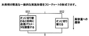
図2及び3は、本発明の簡易な一般的な実施形態を示す。図2A、2B、2Cは、2つの無線局BS1及びBS2の関与するシナリオを示し、単一の協調送信パラメータ調整を有する単純な遷移を示す。 2 and 3 show a simple general embodiment of the present invention. 2A, 2B, 2C show a scenario involving two radio stations BS1 and BS2 and show a simple transition with a single coordinated transmission parameter adjustment.
ここで、BS2はオフ又はオンに切り替えられ、BS1はBS2と同時に自身の送信パラメータを調整する。BS2は、高容量状態でのみ送信するマイクロ無線局として動作する。BS1は、BS2と協調して自身の送信を調整するマクロ無線局として動作する。BS1における送信パラメータ調整は、例えばアンテナチルト又は送信電力であって良い。BS2における送信パラメータ調整も、アンテナチルト又は送信電力であって良く、送信電力をオンに切り替えるステップを含む。 Here, BS2 is switched off or on, and BS1 adjusts its transmission parameters simultaneously with BS2. BS2 operates as a micro radio station that transmits only in a high capacity state. BS1 operates as a macro radio station that coordinates its transmission in coordination with BS2. The transmission parameter adjustment in BS1 may be, for example, antenna tilt or transmission power. The transmission parameter adjustment in BS2 may also be antenna tilt or transmission power, and includes the step of switching transmission power on.
図2Aで、BS2において電源がオンに切り替えられ、実質的に同時にBS1において送信パラメータ調整が行われ、単一の協調ステップで高容量への遷移が行われる。代替として、図2Bは、協調されていない別個のオンへの切り替えを示し、その後、BS1及びBS2で単一の協調送信パラメータ調整ステップが行われ、高容量への遷移が行われる。図2Cは、単一の協調されたステップで低容量への遷移を示す。その後、オフへの切り替えステップが続く。 In FIG. 2A, power is switched on at BS2, and transmission parameter adjustments are made at BS1 substantially simultaneously, and a transition to high capacity occurs in a single coordination step. Alternatively, FIG. 2B shows a separate on-off that is not coordinated, after which a single coordinated transmission parameter adjustment step is performed at BS1 and BS2, and a transition to high capacity is performed. FIG. 2C shows the transition to low capacity in a single coordinated step. This is followed by a switch-off step.
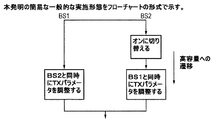
図3も、2つの無線局BS1及びBS2のシナリオを示す。ここで、パラメータの調整は、BS1が調整を終えるまで、BS2が自身のパラメータを調整するのを待つよう協調される。このシナリオは、複数のステップでの調整を含む(これらのステップの少なくとも1つの他のステップに対するタイミングは、予め定められる)。各協調ステップの後に個々の時間遅延が続き、UEハンドオーバを可能にする。個々のステップは、送信電力及び/又はアンテナダウンチルトの調整を含み得る。しかしながら、BS2がマイクロ無線局として動作する場合、BS2について示されたステップのうちの1つ又は前のステップ/次のステップは、状態間遷移の間に無線局のオン/オフへの切り替えを生じる。 FIG. 3 also shows a scenario of two radio stations BS1 and BS2. Here, parameter adjustments are coordinated to wait for BS2 to adjust its parameters until BS1 finishes the adjustment. This scenario includes adjustments in multiple steps (the timing of these steps relative to at least one other step is predetermined). Each coordination step is followed by an individual time delay to enable UE handover. Individual steps may include adjustment of transmit power and / or antenna downtilt. However, if BS2 operates as a micro radio station, one of the steps shown for BS2 or the previous / next step will cause the radio station to switch on / off during the transition between states. .
本発明の実施形態のオーバレイネットワーク構成が用いられるシナリオは、特に、通信事業者が単一のRAT(Radio Access Technology)でモバイルサービスを提供するライセンスを有し、近隣セルの調整無しに異なる容量を提供するために(非干渉周波数帯域である)直交リソースが利用できない場合に適する。 The scenario in which the overlay network configuration of the embodiment of the present invention is used is, in particular, that a carrier has a license to provide mobile services with a single RAT (Radio Access Technology) and has different capacities without adjusting neighboring cells. Suitable when orthogonal resources (which are non-interfering frequency bands) are not available to provide.
ネットワーク通信事業者が既に技術「X」(例えばWCDMA)を通じてモバイルサービスを提供している場合、彼らは既にサービスが提供されているエリアで100%のカバレッジを有する可能性がある。通信事業者が後に技術「Y」(例えばLTE Rel−09)を通じてモバイルサービスを提供するためにスペクトルを取得し、したがって1つより多いRAT技術でサービスを提供するライセンスを取得した場合、取得したスペクトルは「X」のために用いられているものと異なる可能性が非常に高い。容量を拡張するために、「オーバレイネットワーク」は、技術「Y」で展開され得る。このように、2つのネットワーク「X」及び「Y」が共存し、互いに干渉しない。このような場合には、通信事業者が技術「Y」の無線局(eNB又は他の用語では基地局)をオフに切り替えたい場合、容量は影響を受けるが、カバレッジは調整も計画も無しに「X」を通じて依然として維持される。したがって、省エネルギのためのオフへの切り替えは、カバレッジを維持するための調整無しに実施できる。 If network operators are already providing mobile services through technology “X” (eg, WCDMA), they may have 100% coverage in the areas where they are already served. If a carrier later acquires a spectrum to provide mobile services through technology “Y” (eg, LTE Rel-09), and thus acquires a license to provide services with more than one RAT technology, the acquired spectrum Is very likely different from that used for "X". To expand capacity, an “overlay network” can be deployed with technology “Y”. Thus, the two networks “X” and “Y” coexist and do not interfere with each other. In such a case, if the carrier wishes to switch off the technology “Y” radio station (eNB or base station in other terms), the capacity will be affected, but the coverage will not be adjusted or planned Still maintained through "X". Therefore, switching off for energy saving can be performed without adjustment to maintain coverage.
ネットワーク通信事業者が技術「X」のみを通じてモバイルサービスを提供するライセンスを有すると仮定する。しかしながら、十分なスペクトル(例えば30MHz)のライセンスを有するならば、通信事業者は、そのスペクトルを、帯域幅20MHzの「A」と(直交する)帯域幅10MHzの「B」の2つのキャリアに分けることができる。さらに、通信事業者は、幾つかのeNBが「A」で動作し、完全なカバレッジを提供し、幾つかのeNBが「B」で動作し、完全な又は一部のカバレッジを提供し、既に「A」で動作しているeNBにより提供されている容量に追加するようにネットワークを計画しても良い。再び、これは、オーバレイネットワーク(ここでは「B」)が存在する又は存在しないとき、完全なカバレッジがネットワークの少なくとも一部(ここでは「A」)により提供されているオーバレイネットワークに似ている。これは、直交周波数リソースにより2者間に干渉が存在しないためである。したがって、再び、「B」のeNBのオフへの切り替えは、カバレッジを維持するために調整を行うことなく、容易に実施される。 Suppose a network operator has a license to provide mobile services only through technology “X”. However, if you have a license for a sufficient spectrum (eg, 30 MHz), the carrier splits the spectrum into two carriers: “A” with a bandwidth of 20 MHz and “B” with a bandwidth of 10 MHz (orthogonal). be able to. Further, the carrier may have some eNBs operating at “A” to provide full coverage, some eNBs to operate at “B”, providing full or partial coverage, The network may be planned to add to the capacity provided by the eNB operating at “A”. Again, this is similar to an overlay network where full coverage is provided by at least a portion of the network (here “A”) when the overlay network (here “B”) is present or absent. This is because there is no interference between the two due to orthogonal frequency resources. Thus, again, switching the “B” eNB off is easily performed without any adjustments to maintain coverage.
上述の2つの例は例えば状態遷移中にカバレッジを維持するために必ずしも複数の無線局のパラメータ調整による利益を引き出さないので、本発明の実施形態は必ずしも上述の2つの例に適用されない。 Embodiments of the present invention do not necessarily apply to the two examples described above, because the two examples described above do not necessarily derive the benefits of parameter adjustments of multiple radio stations to maintain coverage during state transitions, for example.
<状態間遷移のトリガ>
本発明の実施形態によるオーバレイネットワークにおける状態間の遷移は、無線パラメータが関連する状態の動作に適応されるよう、トラフィック要求の時間的変動に依存して動的にトリガされる。解決策は、次の動作を実行するエンティティによる。
(1)マイクロ←→マクロ遷移のトリガが適用される時点を決定する。
(2)上述のような遷移がUEのサービス品質に最小限の影響しか与えないよう又は如何なる影響も与えないように、無線基地局とシグナリングメッセージを交換する。
<Trigger for transition between states>
Transitions between states in an overlay network according to embodiments of the present invention are dynamically triggered depending on the temporal variation of traffic demands so that the radio parameters are adapted to the behavior of the relevant state. The solution is by an entity that performs the following actions:
(1) Determine when the trigger for the micro ← → macro transition is applied.
(2) Exchange signaling messages with the radio base station so that the transition as described above has a minimal or no influence on the quality of service of the UE.
このようなエンティティは、以下では、LTE用語を用いて「SON(Self Optimising Network)サーバ」と称されるが、この用語は限定的と見なされるべきではない。SONサーバは、1つのeNBセット(単一のクラスタ)又は複数のeNBセット(1つより多いクラスタ)の協調を担うことができる。厳密に言うと、SONサーバは、1又は複数のクラスタに関しては中央エンティティと考えられ得るが、ネットワーク全体に関して又は省エネルギのオフへの切り替え/オーバレイ手順を用いるネットワークの一部に関しては必ずしも中央エンティティではない。SONサーバは、ネットワークの無線基地局のうちの1つに又はOAM若しくはMME/S−GWのような別の中央ネットワークエンティティ内に存在しても良い。これらの例は、3GPP Rel9に基づくシステムに関し、図4及び5に示される。これらの図では、SONサーバとeNBとの間で示されたインタフェースを介して情報交換が行われる。 Such an entity is hereinafter referred to as a “SON (Self Optimising Network) server” using LTE terminology, but this term should not be considered limiting. A SON server may be responsible for coordination of one eNB set (single cluster) or multiple eNB sets (more than one cluster). Strictly speaking, a SON server may be considered a central entity for one or more clusters, but not necessarily a central entity for the entire network or for parts of the network that use energy-saving switch-over / overlay procedures. Absent. The SON server may reside in one of the wireless base stations of the network or in another central network entity such as OAM or MME / S-GW. These examples are shown in FIGS. 4 and 5 for a system based on 3GPP Rel9. In these figures, information is exchanged via the interface shown between the SON server and the eNB.
図4は、LTEの例を示し、SONサーバは無線基地局内にある(分散型構成)。SONサーバとSONサーバを含まない無線局との間の通信は、無線局間のX2インタフェースを介する。(オフへの切り替えが行われる)ネットワーク内には「x」個のクラスタが存在し、各クラスタは多数のeNBを含む。1つのオプションとして、各クラスタから1つのeNBが、マスタとして指名され、(自身のeNBとしての機能に加えて)そのeNBのクラスタのためにSONサーバの機能を実行する。別のオプションとして、x個のクラスタから1つのeNBが、マスタとして指名され、(自身のeNBとしての機能に加えて)そのeNBが属するクラスタ及び幾つかの近隣クラスタのためにSONサーバの機能を実行する。任意のオプションの選択は、通常、クラスタのサイズ、バックホール容量、実装の複雑性のような要因及び他のネットワーク要因に依存する。 FIG. 4 shows an example of LTE, where the SON server is in the radio base station (distributed configuration). Communication between the SON server and a wireless station that does not include the SON server is via an X2 interface between the wireless stations. There are “x” clusters in the network (which is switched off), and each cluster includes a number of eNBs. As an option, one eNB from each cluster is designated as the master and performs the SON server function for that eNB's cluster (in addition to its own eNB function). Another option is that one eNB out of x clusters is designated as the master and (in addition to its own eNB function) the SON server function for the cluster to which it belongs and several neighboring clusters. Run. The choice of any option typically depends on factors such as cluster size, backhaul capacity, implementation complexity, and other network factors.
図5は、LTEの例を示し、SONサーバはMME/S−GW内にある(集中型/ハイブリッド構成)。したがって、SONサーバと全ての無線局との間の通信は、S1インタフェースを介する。 FIG. 5 shows an example of LTE, where the SON server is in the MME / S-GW (centralized / hybrid configuration). Therefore, communication between the SON server and all wireless stations is via the S1 interface.
遷移の前に、送信電力及びアンテナダウンチルトのような関連する無線パラメータは、全ての適用可能な動作状態について全ての無線局について初期化される。これは、ネットワークが、オン/オフ遷移の前及び後の両方でネットワークの無線及びカバレッジ要件を満たせることを保証する。したがって、本発明の実施形態によるオーバレイスキームの異なる状態のパラメータは、予め定められる。所定値に到達するメカニズムは、従来知られている。例えば、1つの適切な方法は、全ての状態におけるトライアル動作である。別の方法は、十分に正確な予測を生成できるようネットワークに対して較正された無線計画/最適化ツールを用いるものである。 Prior to the transition, relevant radio parameters such as transmit power and antenna downtilt are initialized for all radio stations for all applicable operating states. This ensures that the network can meet the radio and coverage requirements of the network both before and after the on / off transition. Accordingly, parameters for different states of the overlay scheme according to embodiments of the present invention are predetermined. The mechanism for reaching the predetermined value is conventionally known. For example, one suitable method is a trial operation in all states. Another method is to use a radio planning / optimization tool that is calibrated to the network so that it can generate sufficiently accurate predictions.
<クラスタの説明>
所与のネットワーク領域内のトラフィック負荷は、空間又は時間領域で均一ではない。例えば、自動車道、劇場、学校、商業複合施設等の存在は、ネットワーク領域内のトラフィック負荷に影響を与えるだろう。本発明の実施形態のオーバレイメカニズムは、近隣のeNBがカバレッジの変化を補償する間、少数のeNBがオフ又はオンに切り替えることによる。したがって、このオーバレイメカニズムは、個々のeNBではなくeNBのグループに適用される必要がある。しかしながら、トラフィック負荷の空間的及び時間的変動のために、オンーオフ遷移をネットワーク全体に適用することは、最適ではなく、実現可能な解決策でもない。したがって、ネットワークは、小さいクラスタ(eNBのグループ)に分解され、小さいクラスタは、該クラスタを構成する全てのeNBの間で事実上相関するトラフィック負荷を有すると考えられる。これらのクラスタは、(オーバレイスキームを実施するために必要な近隣eNBの数に基づき)最小サイズの粒度を有する。しかしながら、eNBの数には上限がない。
<Description of cluster>
The traffic load within a given network area is not uniform in space or time domain. For example, the presence of motorways, theatres, schools, commercial complexes, etc. will affect the traffic load within the network area. The overlay mechanism of an embodiment of the present invention is by a small number of eNBs switching off or on while neighboring eNBs compensate for coverage changes. Therefore, this overlay mechanism needs to be applied to groups of eNBs rather than individual eNBs. However, due to spatial and temporal variations in traffic load, applying on-off transitions throughout the network is not optimal and is not a viable solution. Thus, the network is broken down into small clusters (groups of eNBs) that are considered to have a traffic load that is virtually correlated among all the eNBs that make up the cluster. These clusters have a minimum size granularity (based on the number of neighboring eNBs needed to implement the overlay scheme). However, there is no upper limit to the number of eNBs.
クラスタの最小サイズは、ネットワーク内の無線局の密度及び一般的なネットワーク計画コンセプトにより決定される。例えば、無線局が互いに非常に近い(例えば、密集した都市環境にある)場合、オフにされる各無線局について、影響を受けるカバレッジを補償するには2又は3個の近隣無線局だけで十分であり、したがって、最小クラスタサイズは3個の無線局だけの小さいもので良い。しかしながら、サイト間距離が比較的長い場合(例えば、郊外のシナリオでは)、オフに切り替えられている個々の無線局のカバレッジを補償するために、最大6個の無線局が必要であっても良い。このような場合には、最小クラスタサイズは約7個以上の無線局になるだろう。 The minimum size of the cluster is determined by the density of radio stations in the network and the general network planning concept. For example, if radio stations are very close to each other (eg, in a dense urban environment), for each radio station that is turned off, only two or three neighboring radio stations are sufficient to compensate for the affected coverage. Therefore, the minimum cluster size may be as small as three radio stations. However, if the distance between sites is relatively long (eg, in a suburban scenario), up to six radio stations may be needed to compensate for the coverage of individual radio stations that are switched off. . In such a case, the minimum cluster size will be about 7 or more radio stations.
さらに、これらのクラスタを固定的にしておく理由はない。一例として、平日には地域が「x」個のクラスタ(必ずしも同じサイズではない)に分解され、終末には同一の地域が異なる数の「y」個のクラスタ(再び必ずしも同じサイズではない)に分解されても良い。 Furthermore, there is no reason to keep these clusters fixed. As an example, on weekdays the region is broken into “x” clusters (not necessarily the same size), and at the end the same region is broken into a different number of “y” clusters (again not necessarily the same size). It may be disassembled.
協調状態遷移プロセスは、所与のクラスタ内の全ての無線局に適用される。しかしながら、各クラスタは、個々の又は共通のSONサーバにより独立して扱われる。 The cooperative state transition process is applied to all radio stations in a given cluster. However, each cluster is handled independently by an individual or common SON server.
したがって、用語「クラスタ」は、少なくともネットワークの一部を示し、希にネットワーク全体が単一のクラスタとして扱われる場合には、ネットワーク全体を示す。 Thus, the term “cluster” refers to at least a portion of the network, and rarely refers to the entire network when the entire network is treated as a single cluster.
<オーバレイネットワークにおける動作状態>
上述のように、クラスタ内の無線基地局は、所定の送信電力及びアンテナダウンチルトパラメータを有する任意の適用可能な状態で動作できる。例えば、「n」個の状態で動作するクラスタでは、電力及びダウンチルトパラメータは、n番目の状態でアクティブなeNBの各々について、以下に示す表1のように定めることができる。最小状態はn==1により表される。
<Operation status in overlay network>
As described above, the radio base stations in the cluster can operate in any applicable state with predetermined transmit power and antenna downtilt parameters. For example, in a cluster operating in “n” states, the power and downtilt parameters can be defined as shown in Table 1 below for each eNB active in the nth state. The minimum state is represented by n == 1.
[表1]無線局の状態とクラスタの状態のマトリックス

表1は、「n」個の異なる状態で動作するクラスタ内の「x+1」個の無線局(ラベル「BS」により示す)の状態マトリックステーブルを示す。クラスタの任意の状態でオフである無線局は、その状態の有効なパラメータ(つまり、送信電力及びアンテナチルト)を有しない。しかしながら、(切り替えられたオフ状態へ又はオフ状態からの)遷移を目的として、このような無線局のパラメータ値は、オフへの切り替えの直前又は直後に異なる値に変更される必要がある。 Table 1 shows a state matrix table of “x + 1” radio stations (indicated by the label “BS”) in a cluster operating in “n” different states. A radio station that is off in any state of the cluster does not have valid parameters for that state (ie, transmit power and antenna tilt). However, for the purpose of transition (to or from the switched off state), the parameter values of such radio stations need to be changed to different values immediately before or after switching to off.
したがって、表2は、パラメータ値Pa,b、Ta,bを示す。ここで、パラメータ送信電力及びアンテナチルトに対して、それぞれ、最初の添え字「a」は無線局IDを示し、2番目の添え字「b」はクラスタ状態IDを示す。b==0のとき、遷移手順中に、オフに切り替えられる直前又はオンに切り替えられた直後に無線局により想定されるパラメータ値を示すことに留意する。 Therefore, Table 2 shows the parameter values P a, b and T a, b . Here, for the parameter transmission power and the antenna tilt, the first subscript “a” indicates the wireless station ID, and the second subscript “b” indicates the cluster state ID. Note that when b == 0, the parameter value assumed by the radio station is shown during the transition procedure immediately before being switched off or immediately after being switched on.
[表2]クラスタ状態に対する無線局のパラメータ値
表1及び表2に基づき、異なる無線局状態のパラメータ調整の2つの例を、クラスタの容量が減少するときの状態遷移の異なる例について以下に示す。逆は、遷移が低容量から高容量状態へのときに適用される。
(1)「2」から「1」へのクラスタ状態遷移
a)BS1: P1,2T1,2→P1,1T1,1
b)BS2: P2,2T2,2→P2,0T2,0→オフ
c)BS‘x’&‘x+1: 参加しない(オフに切り替えられたまま)
(2)「n」から「2」へのクラスタ状態遷移
a)BS1: P1,nT1,n→P1,2T1,2
b)BS2: P2,nT2,n→P2,2T2,2
c)BS‘x’: Px,nTx,n→Px,0Tx,0→オフ
d)BS‘x+1’: Px+1,nTx+1,n→Px+1,0Tx+1,0→オフ
オーバレイネットワークにおいて2状態のクラスタを考える場合、このクラスタではn=2であり、つまりクラスタは2つの状態でのみ動作する。状態1及び状態2は次の通りである。
・状態1では、クラスタ内の幾つかの無線基地局がアクティブモードであり、その数を「x」とする。このような無線局の1つは、送信電力P1及びアンテナダウンチルトT1で動作する。
・状態2では、クラスタ内の全ての無線基地局がアクティブモードであり、その数を「y」とする。y>xであり、(より高い容量の状態であり)送信電力P2及びアンテナダウンチルトT2で動作する。
Based on Tables 1 and 2, two examples of parameter adjustments for different radio station states are given below for different examples of state transitions when the cluster capacity decreases. The converse applies when the transition goes from a low capacity to a high capacity state.
(1) Cluster state transition from “2” to “1” a) BS1: P 1,2 T 1,2 → P 1,1 T 1,1
b) BS2: P 2,2 T 2,2 → P 2,0 T 2,0 → off c) BS'x '&' x + 1: not participate (switched off)
(2) Cluster state transition from “n” to “2” a) BS1: P 1, n T 1, n → P 1,2 T 1,2
b) BS2: P 2, n T 2, n → P 2,2 T 2,2
c) BS′x ′: P x, n T x, n → P x, 0 T x, 0 → off d) BS′x + 1 ′: P x + 1, n T x + 1, n → P x +1,0 T x + 1,0 → off When considering a two-state cluster in the overlay network, n = 2 in this cluster, ie the cluster operates only in two states.
In
In
基地局BS1、つまりi=1は状態1及び2の両方でアクティブのままであり(マクロ)、基地局BS2、つまりi=2は状態2のみでアクティブのままである(マイクロ)。このようなシナリオでは、無線局の無線パラメータは、以下ように影響を受ける。
・状態2→状態1の遷移中
BS2は無線パラメータをP22からP20へ及びT22からT20へ変更し、オフに切り替える。
Base station BS1, i = 1, remains active in both
-Transition from
BS1は無線パラメータをP12からP11へ及びT12からT11へ変更し、アクティブのままである。
・状態1→状態2の遷移中
非アクティブな無線基地局BS2は、オンに切り替わり、無線パラメータをP20からP22へ及びT20からT22へ変更する。
BS1 changes the radio parameters from P12 to P11 and from T12 to T11 and remains active.
Transition from
アクティブな無線基地局BS1は、無線パラメータをP11からP12へ及びT11からT12へ変更する。 The active radio base station BS1 changes the radio parameters from P11 to P12 and from T11 to T12.
したがって、2つの状態しか存在しない場合、マクロeNBは、状態n==2からn==1へ遷移し、これらの状態に対応する値は表2に示される。したがって、BS1はP12からP11へ変化する。 Therefore, if there are only two states, the macro eNB transitions from state n == 2 to n == 1 and the values corresponding to these states are shown in Table 2. Therefore, BS1 changes from P12 to P11.
しかしながら、マイクロeNBは、(オフに切り替わるので)状態n==1では全く動作しない。状態0は、次のような区別を定める。つまり、状態0は、eNBが、n==1に対応する値で動作中かアクティブのままではなく、オフに切り替わることを示す。マクロeNBの状態0に対して定められた値は、状態2の値と同じか(つまり、オフに切り替える前のパラメータ調整がない)、又は状態n==2の値と異なっても良い。したがって、本例では、BS2はP22からP20に変更する。 However, the micro eNB does not operate at all in state n == 1 (since it switches off). State 0 defines the following distinction. That is, state 0 indicates that the eNB is not operating or remains active with a value corresponding to n == 1, but is switched off. The value determined for state 0 of the macro eNB may be the same as the value of state 2 (that is, there is no parameter adjustment before switching off) or may be different from the value of state n == 2. Therefore, in this example, BS2 is changed from P22 to P20.
BS2の状態2におけるパラメータ値は、「N/A」と見なされても良い。同様に、BS1の状態0におけるパラメータ値は、「N/A」である。
The parameter value in
オンに切り替える必要のある無線局は、その最終動作の状態で、直接オンに切り替えることができないかも知れない。これは、無線局は、アクティブになると直ぐに、該無線局によりサポートできるよりも多い数のUEによりハンドオーバの試みが行われ得るからである。 A radio station that needs to be switched on may not be able to switch on directly in its final operational state. This is because as soon as a radio station becomes active, a handover attempt may be made by a greater number of UEs than can be supported by the radio station.
したがって、状態0に対して指定されたパラメータ値は、オフに切り替わった無線局が最初に適用すべき(電力及びダウンチルトの)値を表す。その後、最終的な値(つまり、状態2における値)が単一又は複数のステップで達成される。留意すべき点は、マイクロ無線局は状態0でアクティブではないので、状態1に対して定められる値は存在しないことである。しかしながら、(オン/オフ切り替えを除く)状態0のパラメータ値を状態2(マイクロ動作)のパラメータ値と同じにすることは依然として可能である。この場合には、オフに切り替えられた無線局では(電力送信及び/又はダウンチルトの点で)調整が必要ない。
Therefore, the parameter value specified for state 0 represents the value (power and downtilt) that the radio station switched off should apply first. The final value (i.e. the value in state 2) is then achieved in a single or multiple steps. It should be noted that since the micro radio station is not active in state 0, there is no value defined for
マクロ基地局は、状態1及び2の両方でアクティブなので、これらの状態の有効なパラメータを保持しているが、(オフに切り替えないので)状態0については保持していない。
Since the macro base station is active in both
同様の用語を用い、遷移に1つのステップのみが含まれ、BS1がマクロeNBであり、BS2がマイクロeNBである場合、遷移は単一の協調ステップで次のように生じる。
BS1: P12→P11
BS2: P22→P20→オフに切り替える
理論上は、P22==P20が可能であり、この場合には、BS2の遷移はP22→オフに切り替えるように見える。
Using similar terminology, if the transition includes only one step, BS1 is a macro eNB and BS2 is a micro eNB, the transition occurs in a single coordination step as follows:
BS1: P12 → P11
BS2: P22 == P20 is theoretically possible to switch from P22 → P20 → off, and in this case, the transition of BS2 appears to switch from P22 → off.
しかしながら、殆どの環境では、余分なステップP20(P22と同じ値であっても同じ値でなくても良い)が必要であり、オフへの切り替えが生じる前にハンドオーバの時間遅延がある。 However, in most environments, an extra step P20 (which may or may not be the same value as P22) is required, and there is a handover time delay before switching off.
BS2の唯一のステップとしてP22→オフへの切り替えを用いることは、BS2がハンドオーバを可能にするためにオンのままである必要がないので、ハンドオーバのための時間遅延を持たせない。 Using P22 → OFF switching as the only step of BS2 does not have a time delay for handover, as BS2 does not have to remain on to allow handover.
この用語は、2つより多い状態の動作を特徴付けるのにも適する。例えば、BS1が状態1、2、3でアクティブであり、BS2が状態2、3でアクティブであり、BS3が状態3のみでアクティブであるような、クラスタ内に3つの動作状態を有するシナリオでは、eNBに適用される状態及びN/Aは以下の通りである。
BS1:状態0でN/A、3→2→1に遷移。
BS2:状態1でN/A、3→2→0に遷移。
BS3:状態2及び1でN/A、3→0に遷移。
This term is also suitable for characterizing more than two states of operation. For example, in a scenario with three operational states in a cluster, where BS1 is active in
BS1: Transition to N / A, 3 → 2 → 1 in state 0.
BS2: In
BS3: Transition to N / A, 3 → 0 in
次の章では、オーバレイネットワークにおいてある状態から別の状態への遷移を実施する1つの提案されるソリューションを詳細に説明する。上述のように、この処理は、クラスタと称される、ネットワークの全部又は一部を形成する基地局グループ(セル)に適用できる。 In the next section, one proposed solution for implementing a transition from one state to another in the overlay network is described in detail. As described above, this process can be applied to base station groups (cells) that form all or part of a network, called a cluster.
<低容量状態へのオン→オフモード(状態n→状態n−1)遷移のメカニズム>
この遷移は、トラフィック/スループット要求が設定された閾より下に落ちて、クラスタ内の幾つかの無線基地局をオフに切り替えるトリガが起こった結果として生じる。基本的に、クラスタ内の全ての無線局についてトラフィックアクティビティがモニタ及び統合され、全システムトラフィック要件が遷移後に満たされることを保証する。
<Mechanism of transition from ON to OFF mode to low capacity state (state n → state n-1)>
This transition occurs as a result of a trigger that switches off some radio base stations in the cluster when the traffic / throughput demand falls below a set threshold. Basically, traffic activity is monitored and integrated for all radio stations in the cluster to ensure that all system traffic requirements are met after the transition.
<SONサーバのフロー>
「SONサーバ」は、1又は複数のクラスタのトラフィックアクティビティを監視及び記録し、遷移の瞬間を決定し、図6に示したフローのように遷移をトリガする。図6は、マイクロ→マクロモード遷移中のSONサーバのシグナリングフローを示す。
<Flow of SON server>
The “SON server” monitors and records the traffic activity of one or more clusters, determines the moment of transition, and triggers the transition as in the flow shown in FIG. FIG. 6 shows a signaling flow of the SON server during the transition from micro to macro mode.
ステップ6.1:SONサーバは、1又は複数のクラスタの全ての無線基地局(eNB)からの現在のトラフィックアクティビティを連続的に監視する。このような負荷情報を収集するシグナリングメッセージは、固有の又は標準に準拠した実装であって良い。 Step 6.1: The SON server continuously monitors current traffic activity from all radio base stations (eNBs) in one or more clusters. Such signaling messages that collect load information may be specific or standard compliant implementations.
例えば、3GPP Rel9に基づくシステムは、X2又はS1インタフェースを介してeNBの「Load Reporting」機能を用いることができる。「Load Reporting」は、無線リソース(PRBGBRUL/DL&PRBnon-GBRUL/DL)について又はトランスポート層の負荷(UL/DLTNLLoad:low,mid,high,overload)について実行できる。 For example, a system based on 3GPP Rel9 can use the “Load Reporting” function of the eNB via the X2 or S1 interface. “Load Reporting” can be executed for a radio resource (PRBGBRUL / DL & PRBnon-GBRUL / DL) or a transport layer load (UL / DLTNLLoad: low, mid, high, overload).
ステップ6.2:SONサーバは、条件(Transition Instant==True)を調べる。偽の場合、論理はステップ1に戻る。真の場合、SONサーバは、遷移が適用できるクラスタ内のマクロ及びマイクロモード無線基地局(eNB)を特定する。任意で、SONサーバは、遷移のクラスタ状態も特定する。 Step 6.2: The SON server checks the condition (Transition Instant == True). If false, the logic returns to step 1. If true, the SON server identifies the macro and micro-mode radio base stations (eNBs) in the cluster to which the transition can be applied. Optionally, the SON server also identifies the cluster state of the transition.
SONサーバは、マクロ又はマイクロモードの状態を適用することを、クラスタ内の無線基地局(eNB)に通知する。任意で、SONサーバは、UE分布を報告するよう要求する。この要求は、「マイクロ」とされた基地局に対して示される。任意で、SONサーバは、遷移のクラスタ状態もシグナリングする。 The SON server notifies the radio base station (eNB) in the cluster that the macro or micro mode state is to be applied. Optionally, the SON server requests to report the UE distribution. This request is indicated to the base station marked “micro”. Optionally, the SON server also signals the cluster state of the transition.
ステップ6.4:(オプション)SONサーバは、「マイクロ」とされた基地局からUE分布プロファイルを受信する。 Step 6.4: (Optional) The SON server receives the UE distribution profile from the base station marked “micro”.
ステップ6.5:(オプション)SONサーバは、m個のステップのステップサイズプロファイル(x1...xm)dB(電力)及び(y1...ym)度(チルト)及びステップ間の時間間隔(遅延)(t1...tm)を、「マイクロ」及び「マクロ」基地局へシグナリングする。 Step 6.5: (Optional) The SON server determines the step size profile (x1 ... xm) dB (power) and (y1 .... ym) degrees (tilt) of m steps and the time interval between steps ( Delay) (t1 ... tm) is signaled to the "micro" and "macro" base stations.
任意で、SONサーバは、全てのステップの固定ステップサイズ及びステップ間隔を送信しても良い。留意すべき点は、このシグナリングが用いられない場合、ステップサイズ及びステップ間隔の値は、例えば基地局により所定の既定値に設定できることである。 Optionally, the SON server may send a fixed step size and step interval for all steps. It should be noted that if this signaling is not used, the step size and step interval values can be set to predetermined default values, for example by the base station.
<ステップ6〜9は、オプション1及びオプション2に記載される以下の2つの変形により実施され得る>
[オプション1]
ステップ6.6:SONサーバは、時点Ts1でマイクロ→マクロモード遷移のパラメータ調整を実行することを、マクロeNBに通知する。時点は、OFDMAに基づくシステムの場合の「フレーム番号」を含む任意の形式で示すことができる。
<Steps 6 to 9 can be implemented by the following two variations described in
[Option 1]
Step 6.6: The SON server notifies the macro eNB that the parameter adjustment of the micro-to-macro mode transition is performed at the time Ts1. The time point can be indicated in any format including a “frame number” for OFDMA based systems.
ステップ6.7:SONサーバは、時点Ts1から時間(t1+t2...tl)の間、待つ。ここで、l<mはマクロ遷移の時間間隔の数である。 Step 6.7: The SON server waits for a time (t1 + t2 .... tl) from time Ts1. Here, l <m is the number of macro transition time intervals.
ステップ6.6:SONサーバは、時点Ts2でマイクロ→マクロモード遷移のパラメータ調整を実行することを、マイクロeNBに通知する。時点は、OFDMAに基づくシステムの場合の「フレーム番号」を含む任意の形式で示すことができる。 Step 6.6: The SON server notifies the micro eNB that the parameter adjustment of the micro-to-macro mode transition is performed at the time Ts2. The time point can be indicated in any format including a “frame number” for OFDMA based systems.
ステップ6.9:SONサーバは、時点Ts1から時間(t1+t2...tm)の間、待つ。 Step 6.9: The SON server waits for a time (t1 + t2... Tm) from time Ts1.
[オプション2]
ステップ6.6a:SONサーバは、時刻Ts1でマイクロ→マクロモード遷移のパラメータ調整を実行することを、マクロ及びマイクロeNBに通知する。時点は、OFDMAに基づくシステムの場合の「フレーム番号」を含む任意の形式で示すことができる。
[Option 2]
Step 6.6a: The SON server notifies the macro and the micro eNB that the parameter adjustment of the micro-to-macro mode transition is executed at time Ts1. The time point can be indicated in any format including a “frame number” for OFDMA based systems.
ステップ6.7a:SONサーバは、時点Ts1から時間(t1+t2...tm)の間、待つ。 Step 6.7a: The SON server waits for a time (t1 + t2 .... tm) from time Ts1.
ステップ6.8a:Void
ステップ6.9a:Void
(以下のステップは、上述のどちらのオプションにも適用される)
ステップ6.9.5:SONサーバは、ステップ6.3の後及びステップ6.10の前の任意の時点でオフへの切り替え手順を取り消すために、マクロ及び/又はマイクロ基地局にシグナリングする。つまり、ステップ2の遷移状態がオフへの切り替え手順の課程中に逆である場合、SONサーバは、このステップを用いて、基地局がオフへの切り替え手順全体を行うことなく、オン状態である元の状態に戻れるようにする。これにより、遷移(オン→オフ→オン)時間を短縮し、アクティブUEに良好なQoE(Quality of Experience)をもたらす。
Step 6.8a: Voice
Step 6.9a: Voice
(The following steps apply to both options above)
Step 6.9.5: The SON server signals to the macro and / or micro base station to cancel the switch off procedure at any time after step 6.3 and before step 6.10. That is, if the transition state of
ステップ6.10:SONサーバは、「マイクロ」基地局から、オフへの切り替え時点を指示する信号を受信する。 Step 6.10: The SON server receives from the “micro” base station a signal indicating when to switch off.
eNBのフロー
マイクロ→マクロモード遷移中の無線基地局(ここではeNBと称する)端におけるイベントの対応するフローは、オプション1について図7に、オプション2について8に、対応するステップと一緒に示す。
eNB Flow The corresponding flow of events at the end of a radio base station (referred to herein as eNB) during the micro-to-macro mode transition is shown in FIG. 7 for
図7は、オプション1に従うマイクロ→マクロモード遷移中の無線基地局(eNB)のフローを示す。
FIG. 7 shows the flow of the radio base station (eNB) during the micro-to-macro mode transition according to
[オプション1]
ステップ7.1:(オプション)マイクロモードeNBは、SONサーバからUE分布プロファイルを報告するよう要求を受信する。
[Option 1]
Step 7.1: (Optional) The micromode eNB receives a request to report the UE distribution profile from the SON server.
ステップ7.2:(オプション)マイクロモードeNBは、SONサーバからの要求に応答して、アクティブUEの分布プロファイルを送信する。 Step 7.2: (Optional) The micro-mode eNB sends a distribution profile of active UEs in response to a request from the SON server.
ステップ7.3:(オプション)マイクロ及びマクロモードeNBは、パラメータ調整のm個のステップのステップサイズプロファイル(x1...xm)dB及び(y1...ym)度、並びに各々連続する調整間に適用するステップ間隔プロファイル(t1...tm)を受信する。 Step 7.3: (Optional) The micro- and macro-mode eNBs are step size profiles (x1 ... xm) dB and (y1 .... ym) degrees of m steps of parameter adjustment, and between each successive adjustment Step interval profiles (t1 ... tm) to be applied to are received.
ステップ7.4:マクロモードeNBは、SONサーバから信号を受信し、マイクロ→マクロモード遷移の無線パラメータを調整し、時点Ts1で調整を開始する。 Step 7.4: The macro mode eNB receives the signal from the SON server, adjusts the radio parameter of the micro-to-macro mode transition, and starts the adjustment at time Ts1.
ステップ7.5:マクロ及びマイクロモードeNBは、遷移の結果として急に生じると予測されるハンドオーバの数に対応するために、最適化を適用する。このような最適化は、固有の又は標準に準拠した実装であって良い。 Step 7.5: Macro and micro-mode eNBs apply optimization to accommodate the number of handovers that are expected to occur abruptly as a result of the transition. Such optimization may be a specific or standard compliant implementation.
例えば、3GPP Rel9に基づくeNBは、ハンドオーバパラメータ値を、例えばハンドオーバのトリガイベントの特定の閾値を最適化できる。このような最適化は、Mobility Robustness Optimizationと称される。適用可能ならば、最適化は、マクロ及びマイクロモードeNBの両方に対して実行する必要がある。 For example, an eNB based on 3GPP Rel9 can optimize a handover parameter value, for example a specific threshold of a handover trigger event. Such optimization is referred to as Mobility Robustness Optimization. If applicable, optimization should be performed for both macro and micromode eNBs.
同様に、3GPP Rel9に基づくeNBは、利用可能なRACHプリアンブルシーケンスの数を増大させることによりRACH最適化を実行し、ハンドオーバ中の衝突の可能性を最小化できる。これは、マクロモードeNBに対してのみ必要である。 Similarly, eNBs based on 3GPP Rel9 can perform RACH optimization by increasing the number of available RACH preamble sequences and minimize the possibility of collision during handover. This is only necessary for macro mode eNBs.
さらに、マクロモードeNBは、変更の設定を実行し、マクロからマイクロeNBへのUEによる後続のHOの試みをブロックする。 In addition, the macro mode eNB performs change configuration and blocks subsequent HO attempts by the UE from the macro to the micro eNB.
ステップ7.6:目標送信電力値がマクロ及びマイクロモード動作と異なる場合、マクロモードeNBは、送信電力を「xj」dBだけ増大させ、時間期間「tj」の間待ち、目標送信電力値に達するまで処理を繰り返す。「xj」及び「tj」の値は、SONサーバによりシグナリングされるか、又は所定の固定値である。添え字jは、j番目のステップを表す。 Step 7.6: If the target transmission power value is different from the macro and micro mode operation, the macro mode eNB increases the transmission power by “xj” dB, waits for the time period “tj”, and reaches the target transmission power value Repeat until the process. The values of “xj” and “tj” are signaled by the SON server or are predetermined fixed values. The subscript j represents the jth step.
ステップ7.7:自動ハンドオーバは、ステップ7.6の結果として、マイクロeNBからマクロeNBへ、影響を受けるアクティブモードUEにより実行される。 Step 7.7: Automatic handover is performed by the affected active mode UE from the micro eNB to the macro eNB as a result of step 7.6.
ステップ7.8:自動セル再選択は、ステップ7.6の結果として、マイクロeNBからマクロeNBへ、影響を受けるアイドルモードUEにより実行される。 Step 7.8: Automatic cell reselection is performed by the affected idle mode UE from the micro eNB to the macro eNB as a result of step 7.6.
ステップ7.9:マクロモードeNBは、アンテナダウンチルトを「yj」度だけ減少させ、時間期間「tj」の間待ち、目標ダウンチルト値に達するまで処理を繰り返す。「yj」及び「tj」の値は、SONサーバによりシグナリングされるか、又は所定の固定値である。添え字jは、j番目のステップを表す。 Step 7.9: The macro mode eNB decreases the antenna downtilt by “yj” degrees, waits for the time period “tj”, and repeats the process until the target downtilt value is reached. The values of “yj” and “tj” are signaled by the SON server or are predetermined fixed values. The subscript j represents the jth step.
ステップ7.10:自動ハンドオーバは、ステップ7.7の結果として、マイクロeNBからマクロeNBへ、影響を受けるアクティブモードUEにより実行される。 Step 7.10: Automatic handover is performed by the affected active mode UE from the micro eNB to the macro eNB as a result of step 7.7.
ステップ7.11:自動セル再選択は、ステップ7.9の結果として、マイクロeNBからマクロeNBへ、影響を受けるアイドルモードUEにより実行される。 Step 7.11: Automatic cell reselection is performed by the affected idle mode UE from the micro eNB to the macro eNB as a result of step 7.9.
ステップ7.12:マイクロモードeNBは、SONサーバから信号を受信し、マイクロ→マクロモード遷移の無線パラメータを調整し、時点Ts2で調整を開始する。 Step 7.12: The micro mode eNB receives the signal from the SON server, adjusts the radio parameter of the micro → macro mode transition, and starts the adjustment at time Ts2.
ステップ7.13:目標送信電力値がマクロ及びマイクロモード動作と異なる場合、マイクロモードeNBは、送信電力を「xj」dBだけ減少させ、時間期間「tj」の間待ち、目標送信電力値に達するまで処理を繰り返す。「xj」及び「tj」の値は、SONサーバによりシグナリングされるか、又は所定の固定値である。添え字jは、j番目のステップを表す。 Step 7.13: If the target transmission power value is different from the macro and micro mode operation, the micro mode eNB decreases the transmission power by “xj” dB, waits for the time period “tj”, and reaches the target transmission power value Repeat until the process. The values of “xj” and “tj” are signaled by the SON server or are predetermined fixed values. The subscript j represents the jth step.
ステップ7.14:自動ハンドオーバは、ステップ7.13の結果として、マイクロeNBからマクロeNBへ、影響を受けるアクティブモードUEにより実行される。 Step 7.14: Automatic handover is performed by the affected active mode UE from the micro eNB to the macro eNB as a result of step 7.13.
ステップ7.15:自動セル再選択は、ステップ7.13の結果として、マイクロeNBからマクロeNBへ、影響を受けるアイドルモードUEにより実行される。 Step 7.15: Automatic cell reselection is performed by the affected idle mode UE from the micro eNB to the macro eNB as a result of step 7.13.
ステップ7.16:マイクロモードeNBは、アンテナダウンチルトを「yj」度だけ増大させ、時間期間「tj」の間待ち、目標ダウンチルト値に達するまで処理を繰り返す。「yj」及び「tj」の値は、SONサーバによりシグナリングされるか、又は予め定められる。添え字jは、j番目のステップを表す。 Step 7.16: The micro mode eNB increases the antenna downtilt by “yj” degrees, waits for the time period “tj”, and repeats the process until the target downtilt value is reached. The values of “yj” and “tj” are signaled by the SON server or predetermined. The subscript j represents the jth step.
ステップ7.17:自動ハンドオーバは、ステップ7.16の結果として、マイクロeNBからマクロeNBへ、影響を受けるアクティブモードUEにより実行される。 Step 7.17: Automatic handover is performed by the affected active mode UE from the micro eNB to the macro eNB as a result of step 7.16.
ステップ7.18:自動セル再選択は、ステップ7.16の結果として、マイクロeNBからマクロeNBへ、影響を受けるアイドルモードUEにより実行される。 Step 7.18: Automatic cell reselection is performed by the affected idle mode UE from the micro eNB to the macro eNB as a result of step 7.16.
ステップ7.19:マイクロeNBは、全ての接続中のUEをマクロeNBへ強制的にハンドオーバする。遅延は、ハンドオーバ手順が全ての要求されたUEについて完了したことを意味するので、強制HOを開始する前に遅延を設定する必要はない。さらに、強制ハンドオーバは、関与する無線局(アンカ及びターゲット)により開始され制御される。したがって、マイクロ無線局は、残りの接続中UEがハンドオーバするのに要するだけ多くの又は少ない時間しか要しない。これは、最終ステップでは、もはやカバレッジに影響がなく、異なるマイクロ基地局がクラスタ内で異なる時点でオフに切り替える場合に、各マイクロ基地局がオフに切り替える前にその全てのUEをマクロ基地局にハンドオーバする限り、動作に影響を与えないからである。 Step 7.19: The micro eNB forces all connected UEs to handover to the macro eNB. Delay means that the handover procedure has been completed for all requested UEs, so there is no need to set a delay before initiating forced HO. In addition, forced handover is initiated and controlled by participating radio stations (anchors and targets). Thus, the micro radio station takes as much or as little time as necessary for the remaining connected UEs to handover. This means that in the final step, the coverage is no longer affected and if different micro base stations switch off at different times in the cluster, all their UEs are turned into macro base stations before each micro base station switches off. This is because the operation is not affected as long as the handover is performed.
唯一の望ましい特徴は、マイクロ基地局がSONサーバに、自身のオフへの切り替え時点を通知するので、サーバが、遷移手順が完了したか(クラスタ内の全てのマイクロ局から確認を受信したとき)否かを知ることができる点である。これは、SONサーバが、取り消しコマンドを発行するか否かを決定でき、次のサイクルで逆の遷移手順を呼び出すことができる。 The only desirable feature is that the micro base station informs the SON server when it switches off, so that the server has completed the transition procedure (when confirmation is received from all micro stations in the cluster) It is a point that can know whether or not. This allows the SON server to determine whether or not to issue a cancel command and can invoke the reverse transition procedure in the next cycle.
ステップ7.19.5:マクロ及び/又はマイクロ基地局は、ステップ1の後及びステップ21の前の段階でオフへの切り替え手順を取り消すための信号を受信する。このような場合には、マクロ及び/又はマイクロ基地局は、オフへの切り替え手順の更なるステップを放棄する。さらに、マクロ及びマイクロ基地局は、「取り消し」信号が受信されたときに対応する段階で、2.3.2章(オプション1)で定めたように「オンへの切り替え手順」を開始する。
Step 7.19.5: The macro and / or micro base station receives a signal to cancel the switch-off procedure after
ステップ7.20:マイクロeNBは、オフへの切り替えの時点をシグナリングする。 Step 7.20: The micro eNB signals the time of switching off.
ステップ7.21:マイクロeNBは、自身のデジタル/無線処理及び送信回路を非アクティブにすることにより、オフに切り替わる。 Step 7.21: The micro eNB switches off by deactivating its digital / radio processing and transmission circuitry.
図8は、オプション2に従うマイクロ→マクロモード遷移中の無線基地局(eNB)のシグナリングフローを示す。
FIG. 8 shows the signaling flow of the radio base station (eNB) during the micro-to-macro mode transition according to
[オプション2]
ステップ8.1:(オプション)マイクロモードeNBは、SONサーバからUE分布プロファイルを報告するよう要求を受信する。
[Option 2]
Step 8.11: (Optional) The micromode eNB receives a request to report the UE distribution profile from the SON server.
ステップ8.2:(オプション)マイクロモードeNBは、SONサーバからの要求に応答して、アクティブUEの分布プロファイルを送信する。 Step 8.2: (Optional) The micromode eNB sends a distribution profile of active UEs in response to a request from the SON server.
ステップ8.3:(オプション)マイクロ及びマクロモードeNBは、パラメータ調整のステップサイズプロファイル(x1...xm)dB及び(y1...ym)度、並びに各々連続する調整間に適用するステップ間隔プロファイル(t1...tm)を受信する。 Step 8.3: (Optional) Micro- and macro-mode eNBs apply step size profiles (x1 ... xm) dB and (y1 .... ym) degrees of parameter adjustment, and step interval applied between each successive adjustment The profile (t1 ... tm) is received.
ステップ8.4:マクロ及びマイクロモードeNBは、SONサーバから信号を受信し、時間Ts1でマイクロ→マクロモード遷移の無線パラメータを調整する。 Step 8.4: The macro and micro mode eNB receives the signal from the SON server and adjusts the radio parameter of the micro-> macro mode transition at time Ts1.
ステップ8.5:マクロ及びマイクロモードeNBは、遷移の結果として急に生じると予測されるハンドオーバの数に対応するために、最適化を適用する。このような最適化は、前述のように固有の又は標準に準拠した実装であって良い。 Step 8.5: Macro and micro mode eNBs apply optimization to accommodate the number of handovers that are expected to occur suddenly as a result of the transition. Such optimization may be a specific or standard compliant implementation as described above.
さらに、マクロモードeNBは、変更の設定を実行し、マクロからマイクロeNBへのUEによる後続のHOの試みをブロックする。 In addition, the macro mode eNB performs change configuration and blocks subsequent HO attempts by the UE from the macro to the micro eNB.
ステップ8.6:目標送信電力値がマクロ及びマイクロモード動作と異なる場合、以下により、マクロ及びマイクロモードeNBにより同時に送信電力調整が実行される。
・マクロモードeNBは、送信電力を「xj」dBだけ増大させ、時間期間「tj」の間待ち、送信電力に達するまで処理を繰り返す。
・マイクロモードeNBは、送信電力を「xj」dBだけ減少させ、時間期間「tj」の間待ち、送信電力に達するまで処理を繰り返す。
Step 8.6: If the target transmission power value is different from the macro and micro mode operation, the transmission power adjustment is performed simultaneously by the macro and micro mode eNB as follows.
The macro mode eNB increases the transmission power by “xj” dB, waits for the time period “tj”, and repeats the process until the transmission power is reached.
The micro mode eNB decreases the transmission power by “xj” dB, waits for the time period “tj”, and repeats the process until the transmission power is reached.
「xj」及び「tj」の値は、SONサーバによりシグナリングされるか、又は所定の固定値である。添え字jは、j番目のステップを表す。 The values of “xj” and “tj” are signaled by the SON server or are predetermined fixed values. The subscript j represents the jth step.
ステップ8.7:自動ハンドオーバは、ステップ8.6の結果として、マイクロeNBからマクロeNBへ、影響を受けるアクティブモードUEにより実行される。 Step 8.7: Automatic handover is performed by the affected active mode UE from the micro eNB to the macro eNB as a result of step 8.6.
ステップ8.8:自動セル再選択は、ステップ8.6の結果として、マイクロeNBからマクロeNBへ、影響を受けるアイドルモードUEにより実行される。 Step 8.8: Automatic cell reselection is performed by the affected idle mode UE from the micro eNB to the macro eNB as a result of step 8.6.
ステップ8.9:マクロ及びマイクロモードeNBにより、以下により、同時にアンテナダウンチルト調整が実行される。
・マクロモードeNBは、アンテナダウンチルトを「yj」度だけ増大させ、時間期間「tj」の間待ち、目標アンテナダウンチルト値に達するまで処理を繰り返す。
・マイクロモードeNBは、アンテナダウンチルトを「yj」度だけ減少させ、時間期間「tj」の間待ち、目標アンテナダウンチルト値に達するまで処理を繰り返す。
Step 8.9: The antenna downtilt adjustment is performed simultaneously by the macro and micromode eNBs as follows.
The macro mode eNB increases the antenna downtilt by “yj” degrees, waits for the time period “tj”, and repeats the process until the target antenna downtilt value is reached.
The micro mode eNB decreases the antenna downtilt by “yj” degrees, waits for the time period “tj”, and repeats the process until the target antenna downtilt value is reached.
「yj」及び「tj」の値は、SONサーバによりシグナリングされるか、又は所定の固定値である。添え字jは、j番目のステップを表す。 The values of “yj” and “tj” are signaled by the SON server or are predetermined fixed values. The subscript j represents the jth step.
ステップ8.10:自動ハンドオーバは、ステップ8.9の結果として、マイクロeNBからマクロeNBへ、影響を受けるアクティブモードUEにより実行される。 Step 8.10: Automatic handover is performed by the affected active mode UE from the micro eNB to the macro eNB as a result of step 8.9.
ステップ8.11:自動セル再選択は、ステップ8.9の結果として、マイクロeNBからマクロeNBへ、影響を受けるアイドルモードUEにより実行される。 Step 8.11: Automatic cell reselection is performed by the affected idle mode UE from the micro eNB to the macro eNB as a result of step 8.9.
ステップ8.12:マイクロeNBは、全ての接続中のUEをマクロeNBへ強制的にハンドオーバする。遅延は、ハンドオーバ手順が全ての要求されたUEについて完了したことを意味するので、強制HOを開始する前に遅延を設定する必要はない。さらに、強制ハンドオーバは、関与する無線局(アンカ及びターゲット)により開始され制御される。したがって、マイクロ無線局は、残りの接続中UEがハンドオーバするのに要するだけ多くの又は少ない時間しかかからない。これは、最終ステップでは、もはやカバレッジに影響がなく、異なるマイクロ基地局がクラスタ内で異なる時点でオフに切り替える場合に、各マイクロ基地局がオフに切り替える前にその全てのUEをマクロ基地局にハンドオーバする限り、動作に影響を与えないからである。 Step 8.12: The micro eNB forcibly hands over all connected UEs to the macro eNB. Delay means that the handover procedure has been completed for all requested UEs, so there is no need to set a delay before initiating forced HO. In addition, forced handover is initiated and controlled by participating radio stations (anchors and targets). Thus, the micro radio station takes as much or less time as necessary for the remaining connected UEs to handover. This means that in the final step, the coverage is no longer affected and if different micro base stations switch off at different times in the cluster, all their UEs are turned into macro base stations before each micro base station switches off. This is because the operation is not affected as long as the handover is performed.
唯一の望ましい特徴は、マイクロ基地局がSONサーバに、自身のオフへの切り替え時点を通知するので、サーバが、遷移手順が完了したか(クラスタ内の全てのマイクロ局から確認を受信したとき)否かを知ることができる点である。これは、SONサーバが、取り消しコマンドを発行するか否かを決定でき、次のサイクルで逆の遷移手順を呼び出すことができる。 The only desirable feature is that the micro base station informs the SON server when it switches off, so that the server has completed the transition procedure (when confirmation is received from all micro stations in the cluster) It is a point that can know whether or not. This allows the SON server to determine whether or not to issue a cancel command and can invoke the reverse transition procedure in the next cycle.
ステップ8.12.5:マクロ及び/又はマイクロ基地局バは、ステップ1の後及びステップ14の前の段階でオフへの切り替え手順を取り消すための信号を受信する。このような場合には、マクロ及び/又はマイクロ基地局は、オフへの切り替え手順の更なるステップを放棄する。さらに、マクロ及びマイクロ基地局は、「取り消し」信号が受信されたときに対応する段階で、2.3.2章(オプション2)で定めたように「オンへの切り替え手順」を開始する。
Step 8.12.5: The macro and / or micro base station receives a signal for canceling the switch-off procedure after
ステップ8.13:マイクロeNBは、オフへの切り替えの時点をシグナリングする。 Step 8.13: The micro eNB signals the time of switching off.
ステップ8.14:マイクロeNBは、自身のデジタル/無線処理及び送信回路を非アクティブにすることにより、オフに切り替わる。 Step 8.14: The micro eNB switches off by deactivating its digital / radio processing and transmission circuitry.
<マクロ→マイクロモード遷移のメカニズム(状態n→状態n+1)>
この遷移は、トラフィック/スループット要求が設定された閾より上に上昇し、クラスタ内の幾つかの又は全ての無線基地局をオンに切り替えるトリガが起こった結果として生じる。クラスタ内の全ての基地局についてトラフィックアクティビティがモニタ及び統合され、全システムトラフィック要件が遷移後に満たされることを保証する。
<Mechanism of transition from macro to micro mode (state n → state n + 1)>
This transition occurs as a result of a trigger that switches on some or all of the radio base stations in the cluster when the traffic / throughput demand rises above a set threshold. Traffic activity is monitored and integrated for all base stations in the cluster to ensure that all system traffic requirements are met after the transition.
<SONサーバのフロー>
「SONサーバ」は、1又は複数のクラスタのトラフィックアクティビティを監視及び記録し、遷移の瞬間を決定し、図9に示したフローのように遷移をトリガする。
<Flow of SON server>
The “SON server” monitors and records the traffic activity of one or more clusters, determines the moment of transition, and triggers the transition as in the flow shown in FIG.
図9は、オプション1及び2に対応するオフ→オンの切り替え遷移中のSONサーバのフローを示す。
FIG. 9 shows the flow of the SON server during the transition from OFF to ON corresponding to
ステップ9.1:SONサーバは、1又は複数のクラスタの全ての無線基地局(eNB)からの現在のトラフィックアクティビティを連続的に監視する。このような負荷情報を収集するシグナリングメッセージは、固有の又は標準に準拠した実装であって良い。 Step 9.1: The SON server continuously monitors current traffic activity from all radio base stations (eNBs) in one or more clusters. Such signaling messages that collect load information may be specific or standard compliant implementations.
例えば、3GPP Rel9に基づくシステムは、X2又はS1インタフェースを介してeNBの「Load Reporting」機能を用いることができる。「Load Reporting」は、無線リソース(PRBGBRUL/DL&PRBnon-GBRUL/DL)について又はトランスポート層の負荷(UL/DLTNLLoad:low,mid,high,overload)について実行できる。 For example, a system based on 3GPP Rel9 can use the “Load Reporting” function of the eNB via the X2 or S1 interface. “Load Reporting” can be executed for a radio resource (PRBGBRUL / DL & PRBnon-GBRUL / DL) or a transport layer load (UL / DLTNLLoad: low, mid, high, overload).
ステップ9.2:SONサーバは、条件(Transition Instant==True)を調べる。偽の場合、ステップ1へ。真の場合、SONサーバは(任意で)遷移のクラスタ状態を特定し、ステップ3へ。
Step 9.2: The SON server checks the condition (Transition Instant == True). If false, go to
ステップ9.3:SONサーバは、以下を通知する。
・クラスタ内のオフに切り替わった(マイクロ)無線基地局(eNB)に、オンへの切り替え手順の準備をするよう通知する。
・クラスタ内のマクロeNBに、(マイクロeNBの)オンへの切り替え手順の準備をするよう通知する。
Step 9.3: The SON server notifies the following.
Notify the (micro) radio base station (eNB) that has been switched off in the cluster to prepare for the procedure for switching on.
Inform the macro eNB in the cluster to prepare for the switch-on procedure (of the micro eNB).
任意で、SONサーバは、UE分布を報告するよう要求する。この要求は、「マクロ」とされた基地局に対して示される。任意で、SONサーバはまた、オフに切り替わった基地局及びマクロ基地局の両方に遷移のクラスタ状態をシグナリングする。 Optionally, the SON server requests to report the UE distribution. This request is indicated to the base station designated as “macro”. Optionally, the SON server also signals the cluster state of transition to both the base station and the macro base station that have switched off.
ステップ9.4:(オプション)SONサーバは、「マクロ」とされた基地局からUE分布プロファイルを受信する。 Step 9.4: (Optional) The SON server receives the UE distribution profile from the base station marked “macro”.
ステップ9.5:SONサーバは、全てのマクロ及びマイクロモードeNBから、オンへの切り替え初期化の完了メッセージを受信する。オンへの切り替えステップはハンドオーバをトリガする。このステップの後に明確に定められた時間遅延はないが、Ts(開始の時間)は、このような遅延を意味し、以下の基準に基づき定められる。
(1)全てのeNBが、SONサーバに、オンへの切り替えの準備が完了したことを示している。
(2)UEがマクロからマイクロeNBへのハンドオーバを完了するのに要する時間。これは、新しいカバレッジリング(オフへの切り替え手順と異なり、マイクロeNBに接続されたままの全てのUEはハンドオーバされる)及び(可能な場合)UE分布プロファイルに基づき予測される。
Step 9.5: The SON server receives a switch-on initialization complete message from all macro and micromode eNBs. The switch-on step triggers a handover. There is no time delay specifically defined after this step, but Ts (starting time) means such a delay and is determined based on the following criteria.
(1) All eNBs indicate to the SON server that preparations for switching on have been completed.
(2) Time required for the UE to complete handover from the macro to the micro eNB. This is predicted based on the new coverage ring (unlike the switch-off procedure, all UEs that remain connected to the micro eNB are handed over) and (if possible) the UE distribution profile.
ステップ9.6:(オプション)SONサーバは、m個のステップのステップサイズプロファイル(x1...xm)dB及び(y1...ym)度及びステップ間の時間間隔(遅延)(t1...tm)を、「マイクロ」及び「マクロ」基地局へシグナリングする。 Step 9.6: (Optional) The SON server determines the step size profile (x1... Xm) dB and (y1... Ym) degrees of m steps and the time interval (delay) between steps (t1. .Tm) to the “micro” and “macro” base stations.
任意で、SONサーバは、全てのステップの固定ステップサイズ及びステップ間隔を送信しても良い。留意すべき点は、このシグナリングが用いられない場合、ステップサイズ及びステップ間隔の値は、例えば基地局により所定の既定値に設定できることである。 Optionally, the SON server may send a fixed step size and step interval for all steps. It should be noted that if this signaling is not used, the step size and step interval values can be set to predetermined default values, for example by the base station.
<ステップ9.7〜9.9は、オプション1及びオプション2に記載される以下の2つの変形により実施され得る>
[オプション1]
ステップ9.7:SONサーバは、時点Ts1でマクロ→マイクロモード遷移のパラメータ調整を実行することを、マイクロ無線基地局(eNB)に通知する。時点は、OFDMAに基づくシステムの場合の「フレーム番号」を含む任意の形式で示すことができる。
<Steps 9.7 to 9.9 can be implemented by the following two variations described in
[Option 1]
Step 9.7: The SON server notifies the micro radio base station (eNB) to execute the parameter adjustment of the macro → micro mode transition at the time Ts1. The time point can be indicated in any format including a “frame number” for OFDMA based systems.
ステップ9.8:SONサーバは、時間(t1+t2+...tl)の間待つ。ここで。l<m、lはマイクロeNBによるパラメータ調整のステップ数である。 Step 9.8: The SON server waits for time (t1 + t2 + ... tl). here. l <m and l are the number of parameter adjustment steps by the micro eNB.
ステップ9.9:SONサーバは、時点Ts2でマクロ→マイクロモード遷移のパラメータ調整を実行することを、マクロeNBに通知する。時点は、OFDMAに基づくシステムの場合の「フレーム番号」を含む任意の形式で示すことができる。 Step 9.9: The SON server notifies the macro eNB that the macro-to-micro mode transition parameter adjustment is executed at the time Ts2. The time point can be indicated in any format including a “frame number” for OFDMA based systems.
ステップ9.7.5:SONサーバは、ステップ9.3の後及びステップ9.10の前の任意の時点でオンへの切り替え手順を取り消すために、マクロ及び/又はマイクロ基地局にシグナリングする。つまり、ステップ2の遷移状態がオンへの切り替え手順の課程中に逆である場合、SONサーバは、このステップを用いて、基地局がオンへの切り替え手順全体を行うことなく、オフ状態である元の状態に戻れるようにする。これにより、遷移(オフ→オン→オフ)時間を短縮し、良好なエネルギ効率をもたらす。
Step 9.7.5: The SON server signals to the macro and / or micro base station to cancel the switch-on procedure at any time after step 9.3 and before step 9.10. That is, if the transition state of
ステップ9.10:時点Ts1から時間(t1+t2...tm)の後、オンへの切り替え手順が完了する。 Step 9.10: After a time (t1 + t2 .... tm) from time Ts1, the switch-on procedure is completed.
[オプション2]
ステップ9.7a:SONサーバは、以下を同時に通知する。
・マイクロeNBに、マクロ→マイクロモード遷移のパラメータ調整を実行するよう通知する。
・マクロeNBに、マクロ→マイクロモード遷移のパラメータ調整を実行するよう通知する。
[Option 2]
Step 9.7a: The SON server notifies the following simultaneously.
Notify the micro eNB to execute the parameter adjustment of the macro → micro mode transition.
Notify the macro eNB to execute the parameter adjustment of the macro → micro mode transition.
時点Tsでパラメータ調整を開始するよう通知する。時点は、OFDMAに基づくシステムの場合の「フレーム番号」を含む任意の形式で示すことができる。 Notification is made to start parameter adjustment at time Ts. The time point can be indicated in any format including a “frame number” for OFDMA based systems.
ステップ9.7.5a:SONサーバは、ステップ3の後及びステップ8の前の任意の時点で、オンへの切り替え手順を取り消すために、マクロ及び/又はマイクロ基地局にシグナリングしても良い。つまり、ステップ2の遷移状態がオンへの切り替え手順の課程中に逆である場合、SONサーバは、このステップを用いて、基地局がオンへの切り替え手順全体を行うことなく、オフ状態である元の状態に戻れるようにする。これにより、遷移(オフ→オン→オフ)時間を短縮し、良好なエネルギ効率をもたらす。
Step 9.7.5a: The SON server may signal the macro and / or micro base station to cancel the switch-on procedure at any time after
ステップ9.8a:時点Ts1から時間(t1+t2...tm)の後、オンへの切り替え手順が完了する。 Step 9.8a: After a time (t1 + t2 .... tm) from time Ts1, the switch-on procedure is completed.
ステップ9.9a:Void
ステップ9.10a:Void
<eNBのフロー>
マイクロ→マクロモード遷移中の無線基地局(ここではeNBと称する)端におけるイベントの対応するフローは、オプション1について図10に、オプション2について図11に、対応するステップと一緒に示す。
Step 9.9a: Voice
Step 9.10a: Voice
<ENB flow>
The corresponding flow of events at the end of a radio base station (referred to herein as an eNB) during the micro-to-macro mode transition is shown with corresponding steps in FIG. 10 for
図10は、オプション1に従うマクロ→マイクロモード遷移中の無線基地局(eNB)のフローを示す。
FIG. 10 shows the flow of the radio base station (eNB) during the macro → micro mode transition according to
[オプション1]
ステップ10.1:マイクロモード又はオフに切り替わったeNBは、SONサーバからオンへの切り替え手順の準備をするための信号を受信する。マクロモードeNBは、SONサーバからオンへの切り替え手順の準備をするための信号を受信し、(オプション)UE分布プロファイルを要求する。
[Option 1]
Step 10.1: An eNB that has been switched to micro mode or off receives a signal for preparing a switching procedure from the SON server to on. The macro mode eNB receives a signal to prepare for the switch-on procedure from the SON server, and (optionally) requests a UE distribution profile.
ステップ10.2:マイクロモードeNBは、状態0に適用する無線パラメータ値でオンに切り替わり、上述のように幾つかのUEをマイクロeNBにハンドオーバするようトリガする。 Step 10.2: The micro mode eNB switches on with the radio parameter value applied to state 0 and triggers some UEs to hand over to the micro eNB as described above.
ステップ10.3:(オプション)マクロモードeNBは、SONサーバからの要求に応答して、アクティブUEの分布プロファイルを送信する。 Step 10.3: (Optional) The macro mode eNB transmits the active UE distribution profile in response to a request from the SON server.
ステップ10.4:マクロ及びマイクロモードeNBは、遷移の結果として急に生じると予測されるハンドオーバの数に対応するために、最適化を適用する。このような最適化は、前述のように固有の又は標準に準拠した実装であって良い。 Step 10.4: Macro and micro mode eNBs apply optimization to accommodate the number of handovers that are expected to occur suddenly as a result of the transition. Such optimization may be a specific or standard compliant implementation as described above.
ステップ10.5:マイクロ及びマクロモードeNBは、オンへの切り替えの準備の完了をシグナリングする。 Step 10.5: The micro and macro mode eNB signals the completion of preparation for switching on.
ステップ10.6:(オプション)マイクロ及びマクロモードeNBは、パラメータ調整のステップサイズプロファイル(x1...xm)dB及び(y1...ym)度、並びに各々連続する調整間に適用するステップ間隔プロファイル(t1...tm)を受信する。 Step 10.6: (Optional) The micro and macro mode eNBs apply step size profiles (x1... Xm) dB and (y1... Ym) degrees of parameter adjustment, and the step interval applied between each successive adjustment. The profile (t1 ... tm) is received.
ステップ10.7:(オプション)マイクロモードeNBは、SONサーバから、マクロ→マイクロモード遷移の無線パラメータを調整するための信号を受信し、調整を開始する時点Ts1も受信する。 Step 10.7: (Optional) The micro mode eNB receives from the SON server a signal for adjusting the radio parameter of the macro → micro mode transition, and also receives the time Ts1 when the adjustment is started.
ステップ10.8:マイクロモードeNBは、アンテナダウンチルトを「yj」度だけ減少させ、時間期間「tj」の間待ち、目標ダウンチルト値に達するまで処理を繰り返す。「yj」及び「tj」の値は、SONサーバによりシグナリングされるか、又は所定の固定値である。添え字jはステップ数(1〜n)を表す。 Step 10.8: The micro mode eNB decreases the antenna downtilt by “yj” degrees, waits for the time period “tj”, and repeats the process until the target downtilt value is reached. The values of “yj” and “tj” are signaled by the SON server or are predetermined fixed values. The subscript j represents the number of steps (1 to n).
ステップ10.9:自動ハンドオーバは、ステップ10.8の結果として、マイクロeNBからマクロeNBへ、影響を受けるアクティブモードUEにより実行される。 Step 10.9: Automatic handover is performed by the affected active mode UE from the micro eNB to the macro eNB as a result of step 10.8.
ステップ10.10:自動セル再選択は、ステップ10.8の結果として、マイクロeNBからマクロeNBへ、影響を受けるアイドルモードUEにより実行される。 Step 10.10: Automatic cell reselection is performed by the affected idle mode UE from the micro eNB to the macro eNB as a result of step 10.8.
ステップ10.11:マイクロモードeNBは、送信電力を「xj」dBだけ増加させ、時間期間「tj」の間待ち、送信電力に達するまで処理を繰り返す。「xj」及び「tj」の値は、SONサーバによりシグナリングされるか、又は所定の固定値である。添え字jはステップ数(1〜n)を表す。 Step 10.11: The micro mode eNB increases the transmission power by “xj” dB, waits for the time period “tj”, and repeats the process until the transmission power is reached. The values of “xj” and “tj” are signaled by the SON server or are predetermined fixed values. The subscript j represents the number of steps (1 to n).
ステップ10.12:自動ハンドオーバは、ステップ10.11の結果として、マクロeNBからマイクロeNBへ、影響を受けるアクティブモードUEにより実行される。 Step 10.12: Automatic handover is performed by the affected active mode UE from the macro eNB to the micro eNB as a result of step 10.11.
ステップ10.13:自動セル再選択は、ステップ10.11の結果として、マクロeNBからマイクロeNBへ、影響を受けるアイドルモードUEにより実行される。 Step 10.13: Automatic cell reselection is performed by the affected idle mode UE from the macro eNB to the micro eNB as a result of step 10.11.
ステップ10.14:マクロモードeNBは、SONサーバから、マクロ→マイクロモード遷移の無線パラメータを調整するための信号を受信し、パラメータ調整を開始する時点Ts2も受信する。 Step 10.14: The macro mode eNB receives, from the SON server, a signal for adjusting the radio parameter of the macro → micro mode transition, and also receives the time Ts2 at which parameter adjustment is started.
ステップ10.15:マクロモードeNBは、アンテナダウンチルトを「yj」度だけ減少させ、時間期間「tj」の間待ち、目標ダウンチルト値に達するまで処理を繰り返す。「yj」及び「tj」の値は、SONサーバによりシグナリングされるか、又は所定の固定値である。添え字jはステップ数(n+1〜m)を表す。 Step 10.15: The macro mode eNB decreases the antenna downtilt by “yj” degrees, waits for the time period “tj”, and repeats the process until the target downtilt value is reached. The values of “yj” and “tj” are signaled by the SON server or are predetermined fixed values. The subscript j represents the number of steps (n + 1 to m).
ステップ10.16:自動ハンドオーバは、ステップ10.15の結果として、マクロeNBからマイクロeNBへ、影響を受けるアクティブモードUEにより実行される。 Step 10.16: Automatic handover is performed by the affected active mode UE from the macro eNB to the micro eNB as a result of step 10.15.
ステップ10.17:自動セル再選択は、ステップ10.15の結果として、マクロeNBからマイクロeNBへ、影響を受けるアイドルモードUEにより実行される。 Step 10.17: Automatic cell reselection is performed by the affected idle mode UE from the macro eNB to the micro eNB as a result of step 10.15.
ステップ10.18:目標送信電力値がマクロ及びマイクロモード動作と異なる場合、マイクロモードeNBは、送信電力を「xj」dBだけ減少させ、時間期間「tj」の間待ち、目標送信電力値に達するまで処理を繰り返す。「xj」及び「tj」の値は、SONサーバによりシグナリングされるか、又は所定の固定値である。添え字jは、j番目のステップを表す。 Step 10.18: If the target transmission power value is different from the macro and micro mode operation, the micro mode eNB decreases the transmission power by “xj” dB, waits for the time period “tj”, and reaches the target transmission power value Repeat until the process. The values of “xj” and “tj” are signaled by the SON server or are predetermined fixed values. The subscript j represents the jth step.
ステップ10.19:自動ハンドオーバは、ステップ10.18の結果として、マクロeNBからマイクロeNBへ、影響を受けるアクティブモードUEにより実行される。 Step 10.19: Automatic handover is performed by the affected active mode UE from the macro eNB to the micro eNB as a result of step 10.18.
ステップ10.20:自動セル再選択は、ステップ10.18の結果として、マクロeNBからマイクロeNBへ、影響を受けるアイドルモードUEにより実行される。 Step 10.20: Automatic cell reselection is performed by the affected idle mode UE from the macro eNB to the micro eNB as a result of step 10.18.
ステップ10.20.5:マクロ及び/又はマイクロ基地局バは、ステップ1の後及びTs1から時間(t1+t2...tl)後にオンへの切り替え手順が完了するまでの任意の段階で、オンへの切り替え手順を取り消すための信号を受信し得る。このような場合には、マクロ及び/又はマイクロ基地局は、オンへの切り替え手順の更なるステップを放棄する。さらに、マクロ及びマイクロ基地局は、「取り消し」信号が受信されたときに対応する段階で、2.2.2章(オプション1)で定めたように「オフへの切り替え手順」を開始する。
Step 10.20.5: The macro and / or micro base station bar turns on at any stage after
図11は、オプション2に従うマクロ→マイクロモード遷移中の無線基地局(eNB)のフローを示す。
FIG. 11 shows the flow of the radio base station (eNB) during the macro → micro mode transition according to
[オプション2]
ステップ11.1:マイクロモード又はオフに切り替わったeNBは、SONサーバからオンへの切り替え手順の準備をするための信号を受信する。マクロモードeNBは、SONサーバからオンへの切り替え手順の準備をするための信号を受信し、(オプション)UE分布プロファイルを要求する。
[Option 2]
Step 11.1: The eNB that has been switched to the micro mode or off receives a signal for preparing the switching procedure from the SON server to on. The macro mode eNB receives a signal to prepare for the switch-on procedure from the SON server, and (optionally) requests a UE distribution profile.
ステップ11.2:マイクロモードeNBは、状態0に適用する無線パラメータ値でオンに切り替わる。 Step 11.2: The micro-mode eNB switches on with the radio parameter value applied to state 0.
ステップ11.3:(オプション)マクロモードeNBは、SONサーバからの要求に応答して、アクティブUEの分布プロファイルを送信する。 Step 11.3: (Optional) The macro mode eNB sends the active UE distribution profile in response to the request from the SON server.
ステップ11.4:マクロ及びマイクロモードeNBは、遷移の結果として急に生じると予測されるハンドオーバの数に対応するために、最適化を適用する。このような最適化は、前述のように固有の又は標準に準拠した実装であって良い。 Step 11.4: Macro and micro-mode eNBs apply optimization to accommodate the number of handovers that are expected to occur suddenly as a result of the transition. Such optimization may be a specific or standard compliant implementation as described above.
ステップ11.5:マイクロ及びマクロモードeNBは、オンへの切り替えの準備の完了をシグナリングする。 Step 11.5: The micro and macro mode eNB signals the completion of the preparation for switching on.
ステップ11.6:(オプション)マイクロ及びマクロモードeNBは、パラメータ調整のステップサイズプロファイル(x1...xm)dB及び(y1...ym)度、並びに各々連続する調整間に適用するステップ間隔プロファイル(t1...tm)を受信する。 Step 11.6: (Optional) Micro- and macro-mode eNBs apply step size profiles (x1 ... xm) dB and (y1 .... ym) degrees of parameter adjustment, and step interval applied between each successive adjustment The profile (t1 ... tm) is received.
ステップ11.7:(オプション)マイクロ及びマクロモードeNBは、SONサーバから、マクロ→マイクロモード遷移の無線パラメータを調整するための信号を受信し、調整を開始する時点Ts1も受信する。 Step 11.7: (Optional) The micro and macro mode eNB receives a signal for adjusting the radio parameter of the macro → micro mode transition from the SON server, and also receives the time Ts1 when the adjustment is started.
ステップ11.8:マクロ及びマイクロモードeNBにより、以下により、同時にアンテナダウンチルト調整が実行される。
・マクロモードeNBは、アンテナダウンチルトを「yj」度だけ減少させ、時間期間「tj」の間待ち、目標アンテナダウンチルト値に達するまで処理を繰り返す。
・マイクロモードeNBは、アンテナダウンチルトを「yj」度だけ増大させ、時間期間「tj」の間待ち、目標アンテナダウンチルト値に達するまで処理を繰り返す。
Step 11.8: The antenna downtilt adjustment is performed simultaneously by the macro and micromode eNBs as follows.
The macro mode eNB decreases the antenna downtilt by “yj” degrees, waits for the time period “tj”, and repeats the process until the target antenna downtilt value is reached.
The micro mode eNB increases the antenna downtilt by “yj” degrees, waits for the time period “tj”, and repeats the process until the target antenna downtilt value is reached.
「yj」及び「tj」の値は、SONサーバによりシグナリングされるか、又は所定の固定値である。添え字jは、j番目のステップを表す。 The values of “yj” and “tj” are signaled by the SON server or are predetermined fixed values. The subscript j represents the jth step.
ステップ11.9:自動ハンドオーバは、ステップ11.8の結果として、マイクロeNBからマクロeNBへ、影響を受けるアクティブモードUEにより実行される。 Step 11.9: Automatic handover is performed by the affected active mode UE from the micro eNB to the macro eNB as a result of step 11.8.
ステップ11.10:自動セル再選択は、ステップ11.8の結果として、マイクロeNBからマクロeNBへ、影響を受けるアイドルモードUEにより実行される。 Step 11.10: Automatic cell reselection is performed by the affected idle mode UE from the micro eNB to the macro eNB as a result of step 11.8.
ステップ11.11:目標送信電力値がマクロ及びマイクロモード動作と異なる場合、以下により、マクロ及びマイクロモードeNBにより同時に送信電力調整が実行される。
・マクロモードeNBは、送信電力を「xj」dBだけ減少させ、時間期間「tj」の間待ち、送信電力に達するまで処理を繰り返す。
・マイクロモードeNBは、送信電力を「xj」dBだけ増大させ、時間期間「tj」の間待ち、マクロモードeNBにより送信電力が達成されるまで処理を繰り返す。
Step 11.11: If the target transmission power value is different from the macro and micro mode operation, the transmission power adjustment is performed simultaneously by the macro and micro mode eNB as follows.
The macro mode eNB decreases the transmission power by “xj” dB, waits for the time period “tj”, and repeats the process until the transmission power is reached.
The micro mode eNB increases the transmission power by “xj” dB, waits for the time period “tj”, and repeats the process until the transmission power is achieved by the macro mode eNB.
「xj」及び「tj」の値は、SONサーバによりシグナリングされるか、又は所定の固定値である。添え字jは、j番目のステップを表す。 The values of “xj” and “tj” are signaled by the SON server or are predetermined fixed values. The subscript j represents the jth step.
ステップ11.12:自動ハンドオーバは、ステップ11の結果として、マクロeNBからマイクロeNBへ、影響を受けるアクティブモードUEにより実行される。 Step 11.12: Automatic handover is performed by the affected active mode UE from the macro eNB to the micro eNB as a result of step 11.
ステップ11.13:自動セル再選択は、ステップ11の結果として、マクロeNBからマイクロeNBへ、影響を受けるアイドルモードUEにより実行される。 Step 11.13: Automatic cell reselection is performed by the affected idle mode UE from the macro eNB to the micro eNB as a result of step 11.
ステップ11.13.5:マクロ及び/又はマイクロ基地局バは、ステップ1の後及びTs1から時間(t1+t2...tl)後にオンへの切り替え手順が完了するまでの任意の段階で、オンへの切り替え手順を取り消すための信号を受信し得る。このような場合には、マクロ及び/又はマイクロ基地局は、オンへの切り替え手順の更なるステップを放棄する。さらに、マクロ及びマイクロ基地局は、「取り消し」信号が受信されたときに対応する段階で、2.2.2章(オプション2)で定めたように「オフへの切り替え手順」を開始する。
Step 11.13.5: The macro and / or micro base station bar turns on at any stage after
<本発明の実施形態の主な特徴>
<UE分布プロファイル>
用語「UE分布プロファイル」は、単にアクティブモードUEを表すので、より正確には用語「アクティブUE分布プロファイル」であって良い。分布プロファイルは、絶対位置又は相対位置又はセル内の全てのアクティブモードUEのサービングセルからの距離を表す。これを表すある方法は、信号強度(RSRQ/RSRP)の観点である。このようなUE分布プロファイルの使用は、状態遷移の各ステップについてハンドオーバ手順の見込み数を決定するためである。
<Main features of the embodiment of the present invention>
<UE distribution profile>
The term “UE distribution profile” may simply be the term “active UE distribution profile” because it simply represents an active mode UE. The distribution profile represents the absolute or relative position or the distance from the serving cell of all active mode UEs in the cell. One way of representing this is in terms of signal strength (RSRQ / RSRP). The use of such a UE distribution profile is to determine the expected number of handover procedures for each step of state transition.
図12は、高容量から低容量状態への遷移中である2つの近隣eNBを示す。eNBは、先ず、マイクロeNBの外側の輪とマクロeNBの内側の輪として示される同様のカバレッジエリアで開始する。次に、遷移ステップにより、マクロeNBのカバレッジエリアは増大し、同時にマイクロeNBのカバレッジエリアは減少する。これは同心円状の輪により示される。第1のステップで、カバレッジがシフトし、マイクロeNBカバレッジの最も外側の同心円状の輪が除去され、マクロeNBの追加カバレッジの第1の同心円状の輪が追加される。UE「D」は、このカバレッジシフトエリア内に居るので、マイクロeNBからマクロeNBへハンドオーバする。第2のステップで、UE「C」及びUE「B」がカバレッジシフトエリア内に居る。UE「C」は、マイクロeNBから遠いので、UE「B」より早くハンドオーバし得る。したがって、UE「D」、「C」及び「B」は、それらのマイクロeNBからの距離に基づく順番で、ハンドオーバを実行する。留意すべき点は、距離は、ハンドオーバシーケンスの順序を説明するための単なる例として用いられることである。ハンドオーバシーケンスは、無線局からのUE分布プロファイルを送信の角度又は局所的なシャドウイングの影響等のような他のパラメータによっても影響を受け得る。留意すべき点は、UE「A」は、依然として、オフに切り替わるマイクロeNBに対して強制ハンドオーバ手順を行う必要があることである。マクロeNBは、強制ハンドオーバの前にもカバレッジを有すると考えられる。ハンドオーバが自動的にトリガされない唯一の理由は、UE「A」に対してカバレッジがマクロ及びマイクロeNBの両方により提供されるが、マイクロeNBからの信号強度が、マクロeNBよりも強いことである。したがって、強制ハンドオーバの必要がある。 FIG. 12 shows two neighboring eNBs in transition from a high capacity to a low capacity state. The eNB first starts with a similar coverage area shown as the outer ring of the micro eNB and the inner ring of the macro eNB. Next, due to the transition step, the coverage area of the macro eNB increases and at the same time the coverage area of the micro eNB decreases. This is indicated by concentric rings. In the first step, the coverage shifts, the outermost concentric rings of the micro eNB coverage are removed, and the first concentric rings of additional coverage of the macro eNB are added. Since UE “D” is within this coverage shift area, the handover is performed from the micro eNB to the macro eNB. In the second step, UE “C” and UE “B” are in the coverage shift area. Since UE “C” is far from the micro eNB, it may be handed over earlier than UE “B”. Therefore, UEs “D”, “C”, and “B” perform handover in an order based on their distance from the micro eNB. It should be noted that distance is only used as an example to describe the order of handover sequences. The handover sequence may also be affected by other parameters such as the UE distribution profile from the radio station, the angle of transmission or the effects of local shadowing. It should be noted that UE “A” still needs to perform a forced handover procedure for the micro eNB that switches off. The macro eNB is considered to have coverage even before the forced handover. The only reason that the handover is not automatically triggered is that coverage for UE “A” is provided by both the macro and micro eNB, but the signal strength from the micro eNB is stronger than the macro eNB. Therefore, there is a need for forced handover.
マイクロeNBの周りの最も外側の同心円状の輪の半径内に居る全てのUEは、第1のステップ中のUE「D」と同時に、近隣のマクロeNB(ターゲット無線局)へのHOを実行できる。ハンドオーバは、アンカeNBにより制御される。ステップサイズは、同時ハンドオーバの数を制限するために制御される必要がある。実際に、UEは、それらがeNBから同一半径に居ないときでも、同時にハンドオーバをトリガする。UEのeNBに対する実際の位置(距離、角度、高さ)は、信号強度に影響を与える多くの要因のうちのほんの1つに過ぎない。 All UEs within the radius of the outermost concentric ring around the micro eNB can perform HO to neighboring macro eNBs (target radio stations) simultaneously with UE “D” in the first step . Handover is controlled by the anchor eNB. The step size needs to be controlled to limit the number of simultaneous handovers. In fact, the UEs trigger a handover at the same time even when they are not at the same radius from the eNB. The actual location (distance, angle, height) of the UE with respect to the eNB is just one of many factors that affect signal strength.
信号強度(LTEではRSRP/RSRQ)は、UEによりeNBへ報告される1つのパラメータである。このパラメータに基づき、eNBによりハンドオーバの決定が行われる。概して、近隣(ターゲット)eNBにハンドオーバを要求するために、(アンカ)eNBにより異なる基準が用いられ得る。このような基準は、通常、ハンドオーバパラメータの形式でネットワークに対して予め設定される。 Signal strength (RSRP / RSRQ in LTE) is one parameter reported to the eNB by the UE. Based on this parameter, handover is determined by the eNB. In general, different criteria may be used by (anchor) eNBs to request a handover from a neighboring (target) eNB. Such criteria are usually preset for the network in the form of handover parameters.
図12の地理的図形の右に示したグラフは、アンカeNB(本例ではマイクロeNB)からの信号強度及びターゲットeNB(本例ではマクロeNB)からの信号強度を時間に対してUE毎にプロットしたグラフである。地理的図形内の同心円状の輪により示した2つのステップでの遷移による信号強度の変化は、説明を簡単にするため、一定の傾きで示される。専門的な読者は、送信パラメータ調整ステップにおける2つの異なる送信電力の間の変化が、ステップの変化ではなく徐々に増大又は減少することを含むことを理解するだろう。2つの異なるアンテナチルト値の間の変化にも同様のことが言える。代替として、ステップ変化又は傾きの中断(時間遅延を含む)は、送信パラメータ調整により提供される。 The graph shown to the right of the geographical figure in FIG. 12 plots the signal strength from the anchor eNB (micro eNB in this example) and the signal strength from the target eNB (macro eNB in this example) for each UE against time. It is a graph. Changes in signal strength due to transitions in two steps indicated by concentric rings in the geographic figure are shown with a constant slope for ease of explanation. The expert reader will understand that the change between two different transmit powers in the transmission parameter adjustment step involves a gradual increase or decrease rather than a step change. The same is true for the change between two different antenna tilt values. Alternatively, step changes or slope interruptions (including time delays) are provided by transmission parameter adjustment.
所与の例では、任意のUEについて、ターゲットeNBの信号強度がアンカeNBの信号強度を所与のマージンだけ超えると、UEはターゲットeNBへハンドオーバする。留意すべき点は、ハンドオーバに用いられる基準には他の条件を用いても良いこと、このような基準は通常ネットワークに予め設定されることである。ハンドオーバの条件の他の例は、ターゲットeNBからの信号強度が絶対閾を超えること、又はアンカeNBからの信号強度が絶対閾より下に低下することであって良い。 In a given example, for any UE, when the signal strength of the target eNB exceeds the signal strength of the anchor eNB by a given margin, the UE hands over to the target eNB. It should be noted that other criteria may be used for the criteria used for handover, and that such criteria are usually preset in the network. Other examples of handover conditions may be that the signal strength from the target eNB exceeds an absolute threshold, or that the signal strength from the anchor eNB falls below the absolute threshold.
アイドルモードUE(現在使用されていない)は、ハンドオーバ手順を行っていないが、「セル再選択手順(Cell Reselection Procedure:CRS)」と呼ばれる別の手順に従うので、検討する必要がない。CRS手順は、任意のUL又はDLシグナリングを含まないので、UL/DL制御プレーンリソースに制約を課さない。したがって、この処理はステップサイズを決定するときに検討する必要がない。 An idle mode UE (not currently used) does not perform a handover procedure, but does not need to consider because it follows another procedure called "Cell Reselection Procedure (CRS)". The CRS procedure does not impose constraints on UL / DL control plane resources because it does not include any UL or DL signaling. This process therefore does not need to be considered when determining the step size.
<「x」dB及び「y」度のステップ>
「x」dB及び「y」度のステップを定める目的は、eNBの送信パラメータの変化が、結果として該eNB及び近隣eNBの無線カバレッジの変化をもたらすことである。したがって、これは、カバレッジの影響を受ける領域内のアクティブUEのうちの幾つかが、自身の無線リンクを維持するために、呼をドロップすることなく、ハンドオーバする必要のある状況を生成する。したがって、1又は複数のeNBの送信パラメータの変化に対して、ハンドオーバアクティビティの増大するバーストが予測される。所要のハンドオーバ数は、所与の変化に対して十分大きいと、遷移中に、幾つかのUEは呼のドロップ又はRLF(radio link failures、無線リンク障害)を経験し得る。ステップサイズ「x」dB及び「y」度は、ステップ変化毎のハンドオーバ数の制御を提供する。
<Step of “x” dB and “y” degrees>
The purpose of defining “x” dB and “y” degree steps is that a change in the eNB's transmission parameters results in a change in radio coverage of the eNB and neighboring eNBs. This therefore creates a situation where some of the active UEs in the area affected by coverage need to be handed over without dropping the call in order to maintain their radio link. Thus, bursts with increasing handover activity are expected for changes in transmission parameters of one or more eNBs. If the required number of handovers is large enough for a given change, during the transition some UEs may experience call drops or RLF (radio link failures). The step sizes “x” dB and “y” degrees provide control of the number of handovers per step change.
ステップサイズは、クラスタ又はクラスタグループに対して固定値に予め設定されても良い。最小ステップサイズは、製品仕様に応じる。例えば、所与のアンテナが2度の分解能で「+−10度」の遠隔ダウンチルト調整に対応する場合、ステップサイズ「y」は2度より小さくできない。 The step size may be preset to a fixed value for the cluster or cluster group. The minimum step size depends on the product specifications. For example, if a given antenna supports a remote downtilt adjustment of “+ −10 degrees” with a resolution of 2 degrees, the step size “y” cannot be smaller than 2 degrees.
幾つかの例では、ステップサイズを最小分解能の値に設定することは、オン←→オフの切り替え手順の遷移時間の増大をもたらし得る。これは、より大きなステップサイズを定めることにより回避でき、ステップの増大又は減少毎のハンドオーバ数の制御は維持したままである。期待されるハンドオーバ数を推定するために、サービングeNBに対するアクティブモードUEの分布に関する情報を用いることができる。この分布を決定する単純な方法は、UE測定、例えばCQIを、遷移の時の、サービングセルからの各アクティブモードUEの距離を推定する基準として用いることである。この情報は、SONサーバにより、オン→オフ又はオフ→オンへの遷移の最適ステップサイズを決定するために利用され得る。 In some examples, setting the step size to a minimum resolution value may result in an increase in the transition time of the on-to-off switching procedure. This can be avoided by defining a larger step size, and the control of the number of handovers for each step increase or decrease remains maintained. In order to estimate the expected number of handovers, information about the distribution of active mode UEs to the serving eNB can be used. A simple way to determine this distribution is to use UE measurements, eg CQI, as a basis for estimating the distance of each active mode UE from the serving cell at the time of transition. This information can be utilized by the SON server to determine the optimal step size for an on-to-off or off-to-on transition.
<ステップ調整間の時間間隔「t」>
オン→オフ又はオフ→オンへの切り替え遷移中、ダウンチルト及び電力のような送信パラメータは、クラスタ内の複数のeNBにより増大及び/又は減少される。上述のように、送信パラメータのこの変化は、クラスタのカバレッジプロパティに影響を与える。無線カバレッジ及びアクティブモードUEのQoEが遷移中に維持されるためには、各反復(電力又はチルトのステップ変化)は、遷移が完了するまで、クラスタのeNB間で調整される。協調又は(幾つかの環境では)同期は、パラメータ、任意の2つの連続するステップ調整の開始時点間のオフセットのような固定時間遅延である時間間隔「t」を用いることにより達成できる。
<Time interval between step adjustments “t”>
During on-off or off-on switching transitions, transmission parameters such as downtilt and power are increased and / or decreased by multiple eNBs in the cluster. As mentioned above, this change in transmission parameters affects the coverage properties of the cluster. In order for radio coverage and QoE of active mode UEs to be maintained during the transition, each iteration (power or tilt step change) is coordinated between the eNBs of the cluster until the transition is complete. Coordination or (in some circumstances) synchronization can be achieved by using a time interval “t” that is a fixed time delay such as a parameter, an offset between the start of any two successive step adjustments.
「t」の値は、期待される又はステップ変化の結果として開始される全てのハンドオーバのためのハンドオーバ処理を完了するのに必要な合計時間より大きいか若しくはそれに等しい。例えば、3GPP−LTEの場合には、ハンドオーバ処理は、S1又はX2インタフェースを介して各UEについて生じ得る。「t」は、HOのための測定を報告するHOイベントからの時間、Time to Trigger、HO Command&Acknowledgement、Target eNBへのStatus/Resource転送、及び最後にSource eNBでリソースが解放されるまでの時間を有し得る。 The value of “t” is greater than or equal to the total time required to complete the handover process for all handovers that are expected or started as a result of a step change. For example, in the case of 3GPP-LTE, handover processing may occur for each UE via the S1 or X2 interface. “T” is the time from HO event reporting measurement for HO, Time to Trigger, HO Command & Acknowledgment, Status / Resource transfer to Target eNB, and finally time until resource is released in Source eNB Can have.
<パラメータ調整を開始する時点Ts>
信号がパラメータ調整の準備及び開始のためにSONサーバにより複数のeNBへ送信されるとき、信号は、(X2又はS1インタフェースの場合のように)IPネットワークを介して送信されても良い。したがって、メッセージは、eNBにより異なる時点で受信され得る。これは、再び、2.4.2章で述べた理由で、同期を用いる必要がある。パラメータ「パラメータ調整を開始する時点」、「Ts1」又は「Ts2」の使用は、遷移手順がクラスタ内の全てのeNBについて同期して同時に開始することを保証できる。
<Time Ts when parameter adjustment starts>
When a signal is sent by the SON server to multiple eNBs in preparation and initiation of parameter adjustment, the signal may be sent over the IP network (as in the case of X2 or S1 interfaces). Thus, messages can be received at different times by the eNB. This again requires the use of synchronization for the reasons described in section 2.4.2. The use of the parameter “time to start parameter adjustment”, “Ts1” or “Ts2” can ensure that the transition procedure starts synchronously and simultaneously for all eNBs in the cluster.
<「取り消し」コマンドのオプション>
オン→オフ遷移又はその逆のトリガ条件が遷移課程中の逆である場合、遷移処理を中止させ、元の状態に戻ることは有利である。これは、トリガ条件が遷移課程中の逆である場合に、SONサーバによりeNBに対して発行される「取り消し」コマンドを定めることにより達成できる。
<Options for “Cancel” command>
If the on-to-off transition or vice versa trigger condition is reversed during the transition process, it is advantageous to abort the transition process and return to the original state. This can be achieved by defining a “cancel” command issued to the eNB by the SON server when the trigger condition is the reverse during the transition process.
<オプション1及びオプション2の選択>
オン→オフ又はオフ→オン遷移のために設けられた2つのオプションは、無線パラメータ調整段階で主に異なる。無線パラメータ調整は、オプション2で、マイクロ及びマクロモードeNBに対して同期をとられる。利点は、遷移の応答時間が速く、したがって省エネルギの更なる最適化の可能性があることである。しかしながら、マイナス面は、ダウンチルトが、マイクロ→マクロ(又はその逆)に移っているUEにとって更に速いハンドオーバである。ハンドオーバのためにシステムで追加制御が必要な場合、無線パラメータ調整はマイクロ及びマクロレイヤで順次生じるので、オプション1が用いられて良い。これにより、自然ハンドオーバレートを減速させる。図12に、既に議論した速いハンドオーバを提供する第2のオプションを示す。グラフから分かるように、マイクロeNB及びマクロeNBは、それらの送信パラメータを一緒に調整する。
<Selection of
The two options provided for the on-off or off-on transition differ mainly in the radio parameter adjustment phase. Radio parameter adjustment is
図13に、遅いハンドオーバレートを提供する第1のオプションを示す。この図は、図12と類似しており、基本的説明については図12に関連する前の段落を参照のこと。ここで、マクロeNBは、第1の段階で1又は複数の無線パラメータを調整する。第1の段階が完了すると、マイクロeNBは第2の次の段階で1又は複数の無線パラメータを調整する。左にある地理的図形は、第1の段階を示し、マクロeNBがそのカバレッジを広げていることを示す。対応するグラフは、2つのステップで、マクロeNB信号強度が増大し、UE D及びUE Cのハンドオーバが生じていることを示す。UE A及びUE Bは影響を受けない。 FIG. 13 shows a first option for providing a slow handover rate. This figure is similar to FIG. 12, see the previous paragraph relating to FIG. 12 for a basic description. Here, the macro eNB adjusts one or a plurality of radio parameters in the first stage. When the first stage is completed, the micro eNB adjusts one or more radio parameters in the second next stage. The geographic figure on the left shows the first stage, indicating that the macro eNB is expanding its coverage. The corresponding graph shows that in two steps, the macro eNB signal strength is increased and the handover of UE D and UE C is occurring. UE A and UE B are not affected.
第2の段階で、マイクロeNBが自身の無線パラメータを調整すると、その信号強度が減少し、UE Bのハンドオーバを生じる。読者は、マイクロeNBの外側の同心円状の輪に居るUE Dは、マクロeNBに既にハンドオーバされているので、この段階の第1のステップがハンドオーバを生じないことを理解するだろう。第2のステップで、UE B及びUE Cはハンドオーバする。最後のステップは、マイクロeNBを非アクティブにする(オフに切り替える)。このステップの直前に、UE AはマクロeNBにハンドオーバしなければならない。 In the second stage, when the micro eNB adjusts its own radio parameters, its signal strength decreases, resulting in UE B handover. The reader will understand that UE D, which is in a concentric ring outside the micro eNB, has already been handed over to the macro eNB, so the first step of this stage does not cause a handover. In the second step, UE B and UE C are handed over. The last step deactivates (switches off) the micro eNB. Immediately prior to this step, UE A must hand over to the macro eNB.
幾つかの本発明の実施形態は、代替として、交互であるが重なり合う、マイクロ及びマクロeNBの調整を提供し得る。マクロeNBと同様のステップ変化が、マイクロeNBのステップ変化と交互に生じ得る。再び代替として、マクロeNBの電力調整の次にマイクロeNBの電力調整が続き、次にマクロeNBのチルト調整の次にマイクロeNBのチルト調整が続いても良い。このような実施形態は、実装の複雑性を増大させ得るので、おそらく上述のオプション1及び2よりも利点が少ない。
Some embodiments of the present invention may alternatively provide alternating but overlapping micro and macro eNB coordination. A step change similar to a macro eNB may occur alternately with a step change of a micro eNB. Again, alternatively, macro eNB power adjustment may be followed by micro eNB power adjustment, followed by macro eNB tilt adjustment followed by micro eNB tilt adjustment. Such an embodiment may have less advantage than
<クラスタ状態情報をシグナリングするオプション>
クラスタがx→y、ここで|x−y|==m且つm>1である状態を変化するシナリオでは、無線局が目標状態x+1又はx+mのパラメータを調整するか否かを知る方法がない。同じ問題は、オフへの切り替え手順にも存在する。
<Option for signaling cluster status information>
In a scenario where the cluster changes state where x → y, where | x−y | == m and m> 1, there is no way for the radio station to know whether to adjust the parameters of the target state x + 1 or x + m. . The same problem exists in the switch off procedure.
したがって、システムが上述のシナリオに対応する場合、SONサーバから全てのマクロ及びマイクロ無線局へのシグナリングメッセージ「クラスタ状態」のオプションが上述の問題を回避する。つまり、「クラスタ状態」は、無線局が遷移のために準備しなければならない状態の値を示す。 Thus, if the system supports the above scenario, the option of signaling message “cluster state” from the SON server to all macro and micro radio stations avoids the above problem. That is, the “cluster state” indicates a value of a state that the wireless station must prepare for transition.
<主な革新的なコンセプト>
本発明の実施形態は、オン/オフへの切り替えシグナリングメカニズムに、主に以下を新たに提供する。
・状態間の遷移のための、SONサーバ(又は他の対応するエンティティ)と無線局との間のシグナリング手順。
・送信電力及びアンテナダウンチルトの増大調整及び増加の時間間隔のために、ステップサイズ「x」dB及び「y」度。これらは、各ステップ変化で期待される又は推定されたハンドオーバ数に基づき、ステップ毎に適応できる(つまり、適応ステップサイズを提供する)。これは、速いオン←→オフ遷移時間を可能にし、良好なエネルギ効率をもたらすと同時に、同時ハンドオーバ数を注意深く制御する。
・遷移のトリガが遷移課程中の逆である場合に、「取り消し」コマンドを発行することにより、オン→オフ又はオフ→オン手順を反転させるSONサーバの能力。これは、システムの安定性を向上させ、良好なエネルギ効率及びシステム性能の可能性を与える。
<本発明の実施形態の利点>
・実施形態は、遷移中にUEに信頼できるリンク及び十分なカバレッジを提供することを目的とするので、UEに対する信頼できるサービス品質。
<Main innovative concepts>
The embodiment of the present invention mainly provides the following newly to the on / off switching signaling mechanism.
A signaling procedure between the SON server (or other corresponding entity) and the radio station for transitions between states.
Step size “x” dB and “y” degrees for increased adjustment and increased time intervals of transmit power and antenna downtilt. These can be adapted on a step-by-step basis (ie, providing an adaptation step size) based on the expected or estimated number of handovers at each step change. This allows for a fast on ← → off transition time and provides good energy efficiency while at the same time carefully controlling the number of simultaneous handovers.
• The ability of the SON server to reverse the on → off or off → on procedure by issuing a “cancel” command when the transition trigger is the reverse during the transition process. This improves system stability and provides the potential for good energy efficiency and system performance.
<Advantages of Embodiment of the Present Invention>
-Embodiments aim to provide a reliable link and sufficient coverage for the UE during the transition, so reliable quality of service for the UE.
・実施形態は、遷移中に移動しているUEのRACH障害又は衝突の可能性を最小化するので、安定したシステム性能。 -The embodiment minimizes the possibility of RACH failure or collision for UEs moving during the transition, so stable system performance.
・本発明の実施形態の遷移メカニズムは、任意のサイズのクラスタに適用できるので、スケーラブルなソリューション。 A scalable solution because the transition mechanism of embodiments of the present invention can be applied to clusters of any size.
・速い遷移時間及びより制御されたハンドオーバを可能にするために、遷移中の電力及び/又はダウンチルト調整のためのスケーラブルなステップ及びステップ間の間隔による性能効率の損失を有しない、省エネルギの向上。 Energy savings without loss of performance efficiency due to scalable steps and intervals between steps to adjust power and / or downtilt during transitions to allow faster transition times and more controlled handovers Improvement.
実施形態はソリューションの実現のために分散型及び集中型アプローチの両方を可能にするので、実装の柔軟性。 Implementation flexibility allows for both distributed and centralized approaches for solution realization, so implementation flexibility.
本発明の実施形態の種々の特徴は、ハードウェア、1若しくは複数のプロセッサで動作するソフトウェアモジュールとして又は他の適切な技術で実施されてもよい。ある態様の特徴は、他の態様の特徴に適用されても良い。 Various features of embodiments of the invention may be implemented in hardware, as software modules operating on one or more processors, or in any other suitable technique. A feature of one aspect may be applied to a feature of another aspect.
本発明は、上述の任意の方法を実行するコンピュータプログラム又はコンピュータプログラムプロダクト、及び上述の任意の方法を実行するプログラムを格納しているコンピュータ可読媒体も提供する。本発明を実施するコンピュータプログラムは、(非一時的)コンピュータ可読媒体に格納されてもよい。或いは、例えば、インターネットウェブサイトから提供されるダウンロード可能なデータ信号のような信号形式又は任意の他の形式であってもよい。 The present invention also provides a computer program or computer program product for performing any of the above methods, and a computer readable medium storing a program for performing any of the above methods. A computer program implementing the invention may be stored on a (non-transitory) computer-readable medium. Alternatively, it may be in a signal format, such as a downloadable data signal provided from an internet website, or any other format.
Claims (9)
前記方法は、先ず、遷移により生成されると期待されるユーザ機器のハンドオーバの数に従って、遷移のステップ数及び/又はステップサイズを決定するステップ、を有する方法。 A method of clustering cells in a communication network having a switch between a first state in which a first number of radio stations are active and a second state in which a second other number of radio stations are active. The second state is intended to provide the same geographical coverage but different capacity as the first state, the transition between states is performed using transmission parameter adjustments, and the transmission parameter adjustments are a plurality of Performed in one or more steps in time coordination with the radio station ,
The method first comprises determining the number of steps and / or step size of the transition according to the number of user equipment handovers expected to be generated by the transition .
Applications Claiming Priority (1)
| Application Number | Priority Date | Filing Date | Title |
|---|---|---|---|
| PCT/EP2010/059319 WO2012000551A1 (en) | 2010-06-30 | 2010-06-30 | Transition mechanism for energy efficient mobile overlay network |
Publications (2)
| Publication Number | Publication Date |
|---|---|
| JP2013534107A JP2013534107A (en) | 2013-08-29 |
| JP5610074B2 true JP5610074B2 (en) | 2014-10-22 |
Family
ID=43531834
Family Applications (1)
| Application Number | Title | Priority Date | Filing Date |
|---|---|---|---|
| JP2013517037A Expired - Fee Related JP5610074B2 (en) | 2010-06-30 | 2010-06-30 | Transition mechanism of energy efficient mobile overlay network |
Country Status (4)
| Country | Link |
|---|---|
| US (1) | US8818393B2 (en) |
| EP (1) | EP2589235B1 (en) |
| JP (1) | JP5610074B2 (en) |
| WO (1) | WO2012000551A1 (en) |
Families Citing this family (26)
| Publication number | Priority date | Publication date | Assignee | Title |
|---|---|---|---|---|
| CN102083179B (en) * | 2010-08-11 | 2014-04-02 | 电信科学技术研究院 | Control processing method for energy-saving cell and base station |
| WO2012052066A1 (en) * | 2010-10-22 | 2012-04-26 | Telefonaktiebolaget L M Ericsson (Publ) | Methods for cell selection balancing, computer programs and computer program products |
| US20140148213A1 (en) * | 2011-04-20 | 2014-05-29 | Qualcomm Incorporated | Range tuning for open access small cells |
| US9913229B2 (en) | 2011-04-20 | 2018-03-06 | Qualcomm Incorporated | Range tuning for open access small cells |
| JP6191829B2 (en) * | 2012-03-15 | 2017-09-06 | 日本電気株式会社 | Wireless communication system, wireless station, network operation management apparatus, and network optimization method |
| WO2014010987A1 (en) | 2012-07-12 | 2014-01-16 | 엘지전자 주식회사 | Method and device for controlling transmission power in wireless communication system |
| CN104641695B (en) * | 2012-09-14 | 2018-05-11 | 华为技术有限公司 | Energy saving method in cellular communication system |
| WO2014070785A1 (en) * | 2012-10-29 | 2014-05-08 | Zte (Usa) Inc. | Supporting a base station to enter and leave sleep mode in a wireless communication system |
| JP5647662B2 (en) * | 2012-11-27 | 2015-01-07 | ソフトバンクモバイル株式会社 | Femtocell base station, transmission output control method, and transmission output control program |
| US8886209B2 (en) * | 2012-12-12 | 2014-11-11 | At&T Intellectual Property I, L.P. | Long term evolution integrated radio access network system leverage proactive load balancing policy enforcement |
| WO2014104185A1 (en) * | 2012-12-27 | 2014-07-03 | 日本電気株式会社 | Device for controlling wireless parameters, system of device for controlling wireless parameters, method for controlling wireless parameters, and program thereof |
| WO2014126136A1 (en) * | 2013-02-15 | 2014-08-21 | 三菱電機株式会社 | Communication system |
| US9713009B2 (en) * | 2013-03-15 | 2017-07-18 | Hitachi, Ltd. | Dual connectivity of user equipment to macro and small cell in long term evolution system |
| WO2015009937A1 (en) | 2013-07-17 | 2015-01-22 | Huawei Technologies Co., Ltd. | System and methods for multi-objective cell switch-off in wireless networks |
| CA2919984A1 (en) * | 2013-08-12 | 2015-02-19 | Sony Corporation | Communication control apparatus, communication control method, radio communication system and terminal apparatus |
| US9357484B2 (en) * | 2013-11-11 | 2016-05-31 | Avaya Inc. | Elastic wireless control plane |
| IN2013DE03532A (en) * | 2013-12-05 | 2015-06-12 | Alcatel Lucent | |
| WO2015082204A1 (en) * | 2013-12-05 | 2015-06-11 | Alcatel Lucent | Reducing energy consumption of small cell devices |
| WO2016006322A1 (en) * | 2014-07-09 | 2016-01-14 | ソニー株式会社 | Device |
| EP3179771B1 (en) * | 2014-08-07 | 2019-07-03 | Nec Corporation | Wireless communication system, control device, base station, information transmission method, and information reception method |
| CN105814951B (en) * | 2014-09-22 | 2019-07-12 | 华为技术有限公司 | The method and apparatus that control site is opened |
| KR102222789B1 (en) * | 2015-12-28 | 2021-03-03 | 닛본 덴끼 가부시끼가이샤 | Wireless terminal, wireless station, core network node, and methods therefor |
| CN107566031A (en) * | 2016-06-30 | 2018-01-09 | 深圳市广星照明实业有限公司 | Data transmitting, method of reseptance and the device of 433M radio communications |
| JP6842535B2 (en) * | 2016-09-29 | 2021-03-17 | テレフオンアクチーボラゲット エルエム エリクソン(パブル) | Active time processing in 2-step grant |
| JP6873078B2 (en) * | 2018-03-26 | 2021-05-19 | Kddi株式会社 | Information processing equipment, information processing methods, and programs |
| WO2022229258A1 (en) * | 2021-04-30 | 2022-11-03 | Telefonaktiebolaget Lm Ericsson (Publ) | Methods for mobility setting adjustment based on predictions |
Family Cites Families (6)
| Publication number | Priority date | Publication date | Assignee | Title |
|---|---|---|---|---|
| US5890067A (en) * | 1996-06-26 | 1999-03-30 | Bnr Inc. | Multi-beam antenna arrays for base stations in which the channel follows the mobile unit |
| US7586872B2 (en) * | 2003-04-11 | 2009-09-08 | Alcatel-Lucent Usa Inc. | User assignment strategies for hierarchical and other overlay networks |
| US7647046B2 (en) * | 2005-01-12 | 2010-01-12 | Cisco Technology, Inc. | Maintaining uninterrupted service in a wireless access point and client stations thereof |
| JP2006352477A (en) * | 2005-06-15 | 2006-12-28 | Matsushita Electric Ind Co Ltd | Radio communication system, radio base station, monitoring device and control method thereof |
| EP2120493A1 (en) * | 2008-03-19 | 2009-11-18 | Nokia Siemens Networks Oy | Mechanism for automated re-configuration of an access network element |
| CN102318407B (en) * | 2009-02-16 | 2014-07-16 | 瑞典爱立信有限公司 | Controlling cell activation in a radio communication network |
-
2010
- 2010-06-30 WO PCT/EP2010/059319 patent/WO2012000551A1/en active Application Filing
- 2010-06-30 EP EP10737800.2A patent/EP2589235B1/en not_active Not-in-force
- 2010-06-30 JP JP2013517037A patent/JP5610074B2/en not_active Expired - Fee Related
-
2012
- 2012-12-12 US US13/711,845 patent/US8818393B2/en not_active Expired - Fee Related
Also Published As
| Publication number | Publication date |
|---|---|
| US8818393B2 (en) | 2014-08-26 |
| JP2013534107A (en) | 2013-08-29 |
| US20130122913A1 (en) | 2013-05-16 |
| WO2012000551A1 (en) | 2012-01-05 |
| EP2589235A1 (en) | 2013-05-08 |
| EP2589235B1 (en) | 2014-05-07 |
Similar Documents
| Publication | Publication Date | Title |
|---|---|---|
| JP5610074B2 (en) | Transition mechanism of energy efficient mobile overlay network | |
| JP5896193B2 (en) | Reducing paging signaling load in communication systems | |
| KR101613419B1 (en) | Call drop avoidance during radio link failure | |
| EP2742707B1 (en) | Communication system | |
| WO2010104143A1 (en) | Wireless communication system, method, wireless base station, and control station | |
| JP6300971B2 (en) | Base station and controller | |
| CN102474784A (en) | Inter-rat reselection/handover parameter optimisation | |
| CN110225570A (en) | The distribution of system information in wireless access telecommunication system | |
| US11343797B2 (en) | Paging related methods and apparatus | |
| CN102547961A (en) | Method, device and system for synchronizing base stations | |
| CN104219716B (en) | Disturbance coordination method based on ASA auxiliary in isomery TDD junction networks | |
| WO2014012192A1 (en) | Network system with local cluster, central controller, micro base station and macro base station | |
| KR20110002818A (en) | Method for operation of femto base station based on radio access system | |
| JP6190960B2 (en) | Communication system radio coverage reconstruction based on available capacity of compensation cell | |
| CN104519506A (en) | Method and device for self-optimization | |
| Lokhandwala et al. | Phantom Cell Realization in LTE and its performance analysis | |
| WO2012146030A1 (en) | Processing method and system for access node to adjust carrier frequency | |
| Kim et al. | SWITCH: SDN-WLAN Integrated Handover Scheme for QoS-Guaranteed Mobile Service. | |
| WO2011002262A2 (en) | Operating method of femto base station in mobile wireless access system | |
| AU2015203413B2 (en) | Communication system | |
| CN116896780A (en) | Method for timing advance acquisition and maintenance and user equipment | |
| Gonzalez et al. | Seamless handover in 802.11 with automatic power save delivery | |
| CN116711459A (en) | Communication apparatus, infrastructure equipment and method | |
| JP5327490B2 (en) | COMMUNICATION SYSTEM, RADIO BASE STATION DEVICE, RADIO TERMINAL DEVICE, COMMUNICATION CONTROL METHOD, AND COMMUNICATION CONTROL PROGRAM |
Legal Events
| Date | Code | Title | Description |
|---|---|---|---|
| A977 | Report on retrieval |
Free format text: JAPANESE INTERMEDIATE CODE: A971007 Effective date: 20131122 |
|
| A131 | Notification of reasons for refusal |
Free format text: JAPANESE INTERMEDIATE CODE: A131 Effective date: 20131203 |
|
| A521 | Request for written amendment filed |
Free format text: JAPANESE INTERMEDIATE CODE: A523 Effective date: 20140131 |
|
| A02 | Decision of refusal |
Free format text: JAPANESE INTERMEDIATE CODE: A02 Effective date: 20140311 |
|
| A521 | Request for written amendment filed |
Free format text: JAPANESE INTERMEDIATE CODE: A523 Effective date: 20140610 |
|
| A911 | Transfer to examiner for re-examination before appeal (zenchi) |
Free format text: JAPANESE INTERMEDIATE CODE: A911 Effective date: 20140620 |
|
| TRDD | Decision of grant or rejection written | ||
| A01 | Written decision to grant a patent or to grant a registration (utility model) |
Free format text: JAPANESE INTERMEDIATE CODE: A01 Effective date: 20140805 |
|
| A61 | First payment of annual fees (during grant procedure) |
Free format text: JAPANESE INTERMEDIATE CODE: A61 Effective date: 20140818 |
|
| R150 | Certificate of patent or registration of utility model |
Ref document number: 5610074 Country of ref document: JP Free format text: JAPANESE INTERMEDIATE CODE: R150 |
|
| LAPS | Cancellation because of no payment of annual fees |