JP5607465B2 - whistle - Google Patents
whistle Download PDFInfo
- Publication number
- JP5607465B2 JP5607465B2 JP2010197302A JP2010197302A JP5607465B2 JP 5607465 B2 JP5607465 B2 JP 5607465B2 JP 2010197302 A JP2010197302 A JP 2010197302A JP 2010197302 A JP2010197302 A JP 2010197302A JP 5607465 B2 JP5607465 B2 JP 5607465B2
- Authority
- JP
- Japan
- Prior art keywords
- mouthpiece
- whistle
- resonance
- air supply
- resin
- Prior art date
- Legal status (The legal status is an assumption and is not a legal conclusion. Google has not performed a legal analysis and makes no representation as to the accuracy of the status listed.)
- Active
Links
Images


Landscapes
- Toys (AREA)
Description
本願発明はホイッスルに係り、例えばバスケットボール競技等の審判員が使用して好適なホイッスルに関するものである。 The present invention relates to a whistle, and more particularly to a whistle that is suitable for use by a judge such as a basketball player.
現状の審判用ホイッスルは、真鍮などの金属板を所定形状に切断し折り曲げて溶接した金属製ホイッスルと、樹脂を射出成形して得られた各部片を超音波溶着機などで接合した樹脂製ホイッスルに大別できる。 The current referee whistle consists of a metal whistle made by cutting and bending a metal plate, such as brass, into a predetermined shape and welding, and a resin whistle in which each piece obtained by injection molding of resin is joined by an ultrasonic welding machine. Can be broadly divided.
金属製ホイッスルは、歯で咥えられるマウスピース部の噛み割れに対しては問題ないが、振動発生エッジやウインドウェイの精密な加工や複数共鳴室の併設といった複雑な加工ができないため、大音量や立ち上がりの早さが実現できず、観客の多く入る騒音の大きい試合では使われず、樹脂性ホイッスルの採用が増えている。 The metal whistle has no problem with the biting of the mouthpiece that can be gripped by teeth, but it does not allow complicated processing such as precise processing of the vibration generating edge and windway and the addition of multiple resonance chambers. In addition, it is not used in noisy games that attract many spectators, and the use of resin whistles is increasing.
特許文献1には、図12に示すように、送気口101及び送気路を有するマウスピース部102と、当該マウスピース部102の送気路に連通する歌口103a,103b、振動発生エッジ104a,104b及び共鳴室105a,105bを有する共鳴部106とが全て樹脂で成形されて成るホイッスル100が開示されている。
In
しかしながら、バスケットボール等の審判員は、基本的にゲーム中ホイッスルを咥えており、吹き鳴らす際にも手でホイッスルを保持することなく、歯で保持することが多い。それ故、長時間の強い噛む力でホイッスルのマウスピース部102が割れないよう、強度(厚さ)が必要である。
However, a referee such as basketball basically holds a whistle during the game, and often holds the whistle with a tooth without holding the whistle by hand. Therefore, strength (thickness) is necessary so that the
現状の樹脂性ホイッスル100のマウスピース部102では、十分な強度が実現されておらず、数試合の使用で噛み割るトラブルが発生することがある。試合中に噛み割るトラブルの発生を回避するため、審判員はマウスピース部102表面が削れてきたら早めに新品と交換したり、ポケットに予備のホイッスル100を携帯したりしている。
In the
また、歯だけでホイッスルを保持するため、ホイッスルを噛んだ位置で歯が安定することも必要である。歯を安定させるために、特許文献2には、図13に示すように、金属製ホイッスル200の送気口201が形成されたマウスピース部202に弾力性のある覆い203を被せたものが開示されている。また、特許文献3には、図14に示すように、樹脂性ホイッスル300の送気口301が形成されたマウスピース部302に弾力性のある覆い303を被せたものが開示されている。
Further, since the whistle is held only by the teeth, it is necessary that the teeth be stabilized at the position where the whistle is bitten. In order to stabilize the teeth,
上述したように、大きな試合会場で必要な音量や立ち上がりの早さを実現するためには、ホイッスルの振動発生エッジや共鳴室部分が形成される共鳴部を複雑な形状にしなければならない為、樹脂等の射出成形で形成する必要がある。 As mentioned above, in order to achieve the required volume and quick start-up in a large game venue, the resonance part where the whistle's vibration generating edge and the resonance chamber part are formed must have a complicated shape. It is necessary to form by injection molding.
また、歯の安定のために、弾力性のある覆いが必要であるが、噛み割れに対する強度を確保しつつ覆いを被せると、マウスピース部の厚みが厚くなってしまい、咥えた口が開いて、長時間銜え続ける事によるあごへの負担、また、吹き込んだ息がホイッスルの横から漏れるといった不具合が生じる。 In addition, an elastic cover is necessary for the stability of the teeth, but if the cover is covered while securing the strength against biting, the mouthpiece part will become thicker and the mouth will open. There is a problem that the chin is burdened by being barked for a long time, and the breath that has been blown out leaks from the side of the whistle.
そこで、本願発明は上記のような課題を解決するためになされたものであり、大きな試合会場で必要な音量や立ち上がりの早さを実現しつつ、歯が安定し、咥えるのに厚すぎず、かつ噛み割れることがないホイッスルを提供することを目的とするものである。 Therefore, the present invention has been made to solve the above-mentioned problems, and while realizing the necessary volume and quick start-up in a large game venue, the teeth are stable and not too thick to bark. And it aims at providing the whistle which does not bite and break.
本発明は、マウスピース部が送気口及び送気路を有し、樹脂製の共鳴部が前記マウスピース部の送気路に連通する歌口及び共鳴室を有するホイッスルにおいて、マウスピース部は金属製スリーブの外周に弾性樹脂を備えた構成であり、金属製スリーブが歯で噛まれる部分に対応する筒状の送気路対応部と送気路対応部の一端部から延長された一対の送気口対応部と送気路対応部の他端部から延長された一対の連結対応部とを備え、この金属製スリーブにおける角筒状の送気路対応部と一対の送気口対応部との外周が弾性樹脂製の口接触部で覆われ、上記金属製スリーブにおける連結対応部が前記共鳴部における歌口のマウスピース部の側端部に埋め込まれたことを特徴とする。 The present invention, the mouthpiece portion have a air supply port and the air passage, the whistle resonance portion made of resin having a mouthpiece and a resonance chamber communicating with the air passage of the mouthpiece unit, Ma Usupisu portion a configuration in which an elastic resin on the outer periphery of the metallic sleeve, a pair of metal sleeve is extended from one end of the gas feed path corresponding portion cylindrical gas feed path corresponding portion corresponding to the portion to be bitten by the teeth And a pair of connection corresponding parts extended from the other end of the air supply path corresponding part, and a rectangular cylindrical air supply path corresponding part and a pair of air supply ports in this metal sleeve The outer periphery of the metal sleeve is covered with a mouth contact portion made of an elastic resin, and the connection corresponding portion in the metal sleeve is embedded in a side end portion of the mouthpiece portion of the singing mouth in the resonance portion .
本発明によれば、金属製スリーブにおける角筒状の送気路対応部と一対の送気口対応部との外周が弾性樹脂製の口接触部で覆われ、上記金属製スリーブにおける連結対応部が前記共鳴部における歌口のマウスピース部の側端部に埋め込まれたので、人がマウスピース部を咥える場合に、歯が安定し、咥えるのに厚すぎず、マウスピース部が噛み割れることがない。本発明において、金属製スリーブがチタンから成れば、耐食性や強度及び軽量化に優れる。又、本発明において、金属製スリーブにおける連結対応部の一部が歯で噛むことのない位置で外部に露出すれば、金属を使っているのをアピールできる。 According to the onset Ming, the outer periphery of the rectangular tube-shaped air passage corresponding portion and a pair of air openings corresponding portion of the metal sleeve is covered at the mouth contact portion made of elastic resin, corresponding linkages in the metallic sleeve Since the part is embedded in the side end of the mouthpiece part of the singing mouth in the resonance part , when a person grips the mouthpiece part, the teeth are stable and not too thick to grip, the mouthpiece part is It won't bite. In the present invention, if the metal sleeve is made of titanium, it is excellent in corrosion resistance, strength and weight reduction. In the present invention, if a part of the connection corresponding portion in the metal sleeve is exposed to the outside at a position where it is not bitten by teeth, it can be appealed that the metal is used.
以下、本願発明に係るホイッスルの一実施形態を図面を参照して詳細に説明する。 Hereinafter, an embodiment of a whistle according to the present invention will be described in detail with reference to the drawings.
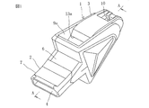
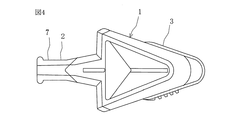
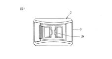
上記の図1〜図7に示すように、本実施形態のホイッスル1は、マウスピース部2と樹脂製共鳴部3とから成っている。マウスピース部2には、唇が当てられ、呼気が吹き込まれる横方向に細長い矩形状の送気口4が設けられている。この送気口4の上下には、マウスピース部2が唇や歯から脱落しないように突部4aが形成されている。本実施形態のマウスピース部2は、送気口4及び送気路5を有する金属製スリーブ6と、金属製スリーブ6を被覆する弾性樹脂製口接触部7とから構成される。金属性スリーブ6を構成する材料としては、ステンレスや真鍮などを用いてもよいが、チタンを用いることによりステンレスや真鍮などを用いた場合よりも耐食性や強度及び軽量化に優れる利点がある。また、弾性樹脂製口接触部7は、例えば、金属製スリーブ6をインサート部材とするインサート成形により、金属製スリーブ6と一体に結合するように樹脂成形により作られる。弾性樹脂製口接触部7を構成する弾性樹脂としては、スチレン系エラストマー、オレフィン系、ウレタン系、ポリエステル系でも良く、さらにはPVC(ポリ塩化ビニル)樹脂等、熱可塑性と弾性及び弾性樹脂製口接触部7を口にくわえる人に安全性を有するものであれば用いることができる。なお、金属スリーブ6は、その一部がマウスピース部2と樹脂製共鳴部3の境界部であって歯で噛むことのない位置に露出しているが、これは意匠的に金属を使っているのをアピールするためである。要するに、ホイッスル1は、樹脂製共鳴部3とマウスピース部2の金属製スリーブ6とマウスピース部2の弾性樹脂製口接触部7とが相互に結合した構成である。
As shown in FIGS. 1 to 7 described above, the
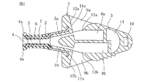
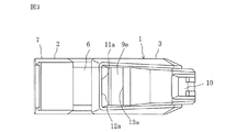
とりわけ、図2に示すように、樹脂製共鳴部3には、内部に長さの異なる2個の管状空間より成る第1,第2共鳴室8a,8bが、送気口4の長手方向を左右方向としたとき上下となるよう配置されている。送気口4からの送気路5が2つに分岐された第1,第2送気路5a,5bと第1,第2共鳴室8a,8bとの間には、第1,第2歌口9a,9bが開口している。また、樹脂製共鳴部3の先端には、吊り下げ紐用の孔10が形成されている。この樹脂製共鳴部3には、空間14が第1,第2共鳴室8a,8bと吊り下げ紐用の孔10と間に位置して設けられる。この空間14は、樹脂製共鳴部3の成形のしやすさと樹脂製共鳴部3を構成する樹脂材料の削減とを主目的としたものであって、設けらない場合もある。樹脂製共鳴部3は、ABS(アクリロニトリル、ブタジエン、スチレン共重合)樹脂で射出成形されるが、PP(ポリプロピレン)樹脂やPC(ポリカーボネート)樹脂等の熱可塑性を有する樹脂であれば可能で、またエラストマーを使用して弾性を持たせることもできる。
In particular, as shown in FIG. 2, the
また、本願出願人による特許第3563046号公報に示されているように、上記第1,第2歌口9a,9bのマウスピース部2側端部及び左右に、第1,第2送気路5a,5b に対し縦方向に延びる壁面11a ,11bを有して成る第1,第2変流体12a,12bが形成されており、それぞれ第1,第2送気路5a,5bから第1,第2歌口9a,9bを通って外部へ放出される空気の流れを変える作用を成している。第1,第2変流体12a,12bの壁面11a,11bは、第1,第2送気路5a,5bの吹き出し方向に対し、直角に形成するのが最も好ましく、この角度関係にある場合に最も大きな変流作用が得られ、高次倍音を増加させて大きな音が得られることを実験により確認している。しかしながら、正確に直角でなくとも実質的に直角、すなわちこれに近い角度であれば同様の作用が得られる。この角度が内側あるいは外側に直角位置から外れるにしたがって変流作用が低下する。また壁面11a,11bは平面であることが望ましい。この壁面11a ,11bに突起等平面性を妨げるものがあると、耳障りな風切音等雑音が発生するからである。第1,第2歌口9a,9bの樹脂製共鳴部3側端部には振動発生エッジ13a,13bが形成されており、ここで、エッジトーンを発生する。振動発生エッジ13a,13bの位置は、第1,第2送気路5a,5bの空気吹き出し方向よりも外側に位置している。
In addition, as shown in Japanese Patent No. 3563046 filed by the applicant of the present application, the first and second air supply passages are provided on the
次に、上記のような構成されたホイッスル1の製造工程(製造方法)について、図8〜図11を参照して詳細に説明する。
Next, the manufacturing process (manufacturing method) of the
まず、図8に示すように、チタン板材を所定形状に切断し折り曲げ加工により、細長い矩形状で長辺側端部が外側に曲がった部分が送気口4及びこれに連なる送気路5を形成する一方、2つに分岐する送気路5a,5b(図2参照)に対応して各片側片6a,6bが両側に広げられると共に、それらの各端部6c,6dがさらに外側に略直角に折り曲げ加工された金属スリーブ6を形成する。
First, as shown in FIG. 8, the titanium plate material is cut into a predetermined shape and bent to form an elongated rectangular shape with a long-side end bent outward, and the air-feeding
次に、上記で形成した金属スリーブ6を図示しない金型にインサートして熱溶融したスチレン系エラストマーで射出成形することにより、図9Aに示すような金属スリーブ6の外面に弾性樹脂製口接触部7が一体成形されたマウスピース部2を形成する。このマウスピース部2のサイズとしては、ゲーム中ホイッスルを咥え続ける審判員にとって、使用可能範囲は幅15mm〜25mm、厚み3mm〜10mmで、最適範囲は、幅18mm〜20mm、厚み5mm〜7mmである。従来の樹脂製ホイッスルに弾力性のある覆いをしたもので上述した最適範囲の厚みを実現したものは我々が知る限りなかったが、本実施形態のようにマウスピースの噛み割れに対して、強度を出す金属材料を、一体成形することにより、十分に可能となり、且つ、噛み割れることも無くなった。
Next, the
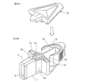
また、図9Bに示すように、第1,第2共鳴室8a,8bを有すると共に、これらに向かって分岐する第1,第2送気路5a,5bと上記金属スリーブ6の各片側片6a,6bの先端部に形成された折曲部6c,6dが挿入される溝部3c,3dが形成された共鳴部ロア3aをABSで射出成形する。そして、図9Bに破線で示すように上記で一体成形したマウスピース部2の各片側片6a,6bの先端部の折曲部6c,6dを溝部3c,3dに挿入する。
Further, as shown in FIG. 9B, the first and
次に、上記共鳴部ロア3aと同様にABSで射出成形された図10Aに示すような共鳴部アッパー(蓋)3bを、図10Bに示すようにマウスピース部2が装着された共鳴部ロア3aの開放側に取り付け、超音波溶着(熱板溶着でも可)又は接着によりロア3aとアッパー3bを接合すると、図11に示すような本実施形態のホイッスル1が完成する。この完成したホイッスル1は、樹脂製共鳴部3とマウスピース部2の金属製スリーブ6とマウスピース部2の弾性樹脂製口接触部7とが相互に結合した構成になっている。
Next, the resonance part upper (lid) 3b as shown in FIG. 10A injection-molded with ABS in the same manner as the resonance part lower 3a is replaced with the resonance part lower 3a to which the
以上のように構成された本実施形態のホイッスル1は、樹脂製共鳴部3が樹脂(ABS)で成形されているので、振動発生エッジやウインドウェイの精密な加工や複数共鳴室の併設といった複雑な加工ができるため、大きな試合会場で必要な音量や立ち上がりの早さを実現することができる。また、マウスピース部2は金属スリーブ6の外周にエラストマー7が一体成形されているので、歯が安定し、咥えるのに厚すぎず、かつ噛み割れることがないという、本願発明特有の顕著な効果が得られる。
In the
なお、上記実施形態では、樹脂製共鳴部3が長さの異なる2個の第1,第2共鳴室8a,8bからなるものに本願発明を適用したものについて説明したが、例えば、特許文献1,3記載のように、上部に2個、下部に1個で、計3個の共鳴室を有するものにも適用可能で、さらには3個以上の複数の共鳴室を有するものにも本願発明は適用可能であり、その場合、送気路、歌口、及び振動発生エッジも対応した数備えられる。
In the above-described embodiment, the case where the present invention is applied to the case where the resin-made
1 ホイッスル
2 マウスピース部
3 共鳴部
3a 共鳴部ロア
3b 共鳴部アッパー
3c 溝部
3d 溝部
4 送気口
4a 突部
5 送気路
5a 第1送気路
5b 第2送気路
6 金属製スリーブ
6a 片側片
6b 片側片
6c 端部(折曲部)
6d 端部(折曲部)
7 弾性樹脂製口接触部
8a 第2共鳴室
8b 第2共鳴室
9a 第1歌口
9b 第2歌口
10 吊り下げ紐用孔
11a 壁面
11b 壁面
12a 第2変流体
12b 第2変流体
13a 振動発生エッジ
13b 振動発生エッジ
DESCRIPTION OF
6d end (folded part)
7 elastic resin
Claims (3)
Priority Applications (1)
| Application Number | Priority Date | Filing Date | Title |
|---|---|---|---|
| JP2010197302A JP5607465B2 (en) | 2010-09-03 | 2010-09-03 | whistle |
Applications Claiming Priority (1)
| Application Number | Priority Date | Filing Date | Title |
|---|---|---|---|
| JP2010197302A JP5607465B2 (en) | 2010-09-03 | 2010-09-03 | whistle |
Publications (2)
| Publication Number | Publication Date |
|---|---|
| JP2012053368A JP2012053368A (en) | 2012-03-15 |
| JP5607465B2 true JP5607465B2 (en) | 2014-10-15 |
Family
ID=45906717
Family Applications (1)
| Application Number | Title | Priority Date | Filing Date |
|---|---|---|---|
| JP2010197302A Active JP5607465B2 (en) | 2010-09-03 | 2010-09-03 | whistle |
Country Status (1)
| Country | Link |
|---|---|
| JP (1) | JP5607465B2 (en) |
Families Citing this family (1)
| Publication number | Priority date | Publication date | Assignee | Title |
|---|---|---|---|---|
| KR20180001577U (en) * | 2016-11-18 | 2018-05-28 | 박태하 | Tooth protection mouthpiece for whistle or whistle |
Family Cites Families (5)
| Publication number | Priority date | Publication date | Assignee | Title |
|---|---|---|---|---|
| KR900009104A (en) * | 1988-12-13 | 1990-07-02 | 제임스 킨케이드 도날드 | Offset mouthpiece |
| JPH066193U (en) * | 1992-06-26 | 1994-01-25 | 一夫 八木 | Diving mouthpiece |
| JP3563046B2 (en) * | 2000-07-24 | 2004-09-08 | 株式会社モルテン | whistle |
| US20030033970A1 (en) * | 2001-08-17 | 2003-02-20 | Graham Hills | Whistle with cushioned mouthpiece |
| US8382549B2 (en) * | 2007-10-19 | 2013-02-26 | Hideomi Shishido | Whistle |
-
2010
- 2010-09-03 JP JP2010197302A patent/JP5607465B2/en active Active
Also Published As
| Publication number | Publication date |
|---|---|
| JP2012053368A (en) | 2012-03-15 |
Similar Documents
| Publication | Publication Date | Title |
|---|---|---|
| USD603374S1 (en) | Programmable sound player | |
| USD524889S1 (en) | Golf club head | |
| USD512116S1 (en) | Rear wall portion of golf club putter head | |
| USD557256S1 (en) | Speaker for a digital media player | |
| USD558227S1 (en) | Media player | |
| USD535344S1 (en) | Golf putter head cover | |
| USD561857S1 (en) | Golf club head cover | |
| USD531310S1 (en) | Dental instrument handle | |
| USD576698S1 (en) | Putter head | |
| USD571823S1 (en) | Media player | |
| USD579921S1 (en) | Speaker grill | |
| USD572729S1 (en) | Media player | |
| USD526375S1 (en) | Head for golf club | |
| USD551451S1 (en) | Game pouch | |
| JP3563046B2 (en) | whistle | |
| USD549294S1 (en) | Golf club head cover | |
| USD558841S1 (en) | Elliptical exerciser | |
| USD554214S1 (en) | Golf club face | |
| USD546348S1 (en) | Audio player | |
| USD544937S1 (en) | Golf club face | |
| USD567224S1 (en) | Audio speaker for sound machine | |
| JP5607465B2 (en) | whistle | |
| USD571825S1 (en) | Media player | |
| USD529974S1 (en) | Back design for a golf club iron head | |
| USD575264S1 (en) | Voice recording/reproducing device |
Legal Events
| Date | Code | Title | Description |
|---|---|---|---|
| A621 | Written request for application examination |
Free format text: JAPANESE INTERMEDIATE CODE: A621 Effective date: 20130718 |
|
| A131 | Notification of reasons for refusal |
Free format text: JAPANESE INTERMEDIATE CODE: A131 Effective date: 20140430 |
|
| A521 | Request for written amendment filed |
Free format text: JAPANESE INTERMEDIATE CODE: A523 Effective date: 20140620 |
|
| A521 | Request for written amendment filed |
Free format text: JAPANESE INTERMEDIATE CODE: A523 Effective date: 20140716 |
|
| TRDD | Decision of grant or rejection written | ||
| A01 | Written decision to grant a patent or to grant a registration (utility model) |
Free format text: JAPANESE INTERMEDIATE CODE: A01 Effective date: 20140808 |
|
| A61 | First payment of annual fees (during grant procedure) |
Free format text: JAPANESE INTERMEDIATE CODE: A61 Effective date: 20140828 |
|
| R150 | Certificate of patent or registration of utility model |
Ref document number: 5607465 Country of ref document: JP Free format text: JAPANESE INTERMEDIATE CODE: R150 |
|
| R250 | Receipt of annual fees |
Free format text: JAPANESE INTERMEDIATE CODE: R250 |
|
| R250 | Receipt of annual fees |
Free format text: JAPANESE INTERMEDIATE CODE: R250 |
|
| R250 | Receipt of annual fees |
Free format text: JAPANESE INTERMEDIATE CODE: R250 |
|
| R250 | Receipt of annual fees |
Free format text: JAPANESE INTERMEDIATE CODE: R250 |
|
| R250 | Receipt of annual fees |
Free format text: JAPANESE INTERMEDIATE CODE: R250 |
|
| R250 | Receipt of annual fees |
Free format text: JAPANESE INTERMEDIATE CODE: R250 |
|
| R250 | Receipt of annual fees |
Free format text: JAPANESE INTERMEDIATE CODE: R250 |
|
| R250 | Receipt of annual fees |
Free format text: JAPANESE INTERMEDIATE CODE: R250 |
|
| R250 | Receipt of annual fees |
Free format text: JAPANESE INTERMEDIATE CODE: R250 |