JP5597885B2 - LPP, EUV light source drive laser system - Google Patents
LPP, EUV light source drive laser system Download PDFInfo
- Publication number
- JP5597885B2 JP5597885B2 JP2008519481A JP2008519481A JP5597885B2 JP 5597885 B2 JP5597885 B2 JP 5597885B2 JP 2008519481 A JP2008519481 A JP 2008519481A JP 2008519481 A JP2008519481 A JP 2008519481A JP 5597885 B2 JP5597885 B2 JP 5597885B2
- Authority
- JP
- Japan
- Prior art keywords
- laser
- pulse
- laser beam
- euv light
- light source
- Prior art date
- Legal status (The legal status is an assumption and is not a legal conclusion. Google has not performed a legal analysis and makes no representation as to the accuracy of the status listed.)
- Active
Links
Images


Classifications
-
- H—ELECTRICITY
- H05—ELECTRIC TECHNIQUES NOT OTHERWISE PROVIDED FOR
- H05G—X-RAY TECHNIQUE
- H05G2/00—Apparatus or processes specially adapted for producing X-rays, not involving X-ray tubes, e.g. involving generation of a plasma
- H05G2/001—X-ray radiation generated from plasma
- H05G2/003—X-ray radiation generated from plasma being produced from a liquid or gas
-
- H—ELECTRICITY
- H05—ELECTRIC TECHNIQUES NOT OTHERWISE PROVIDED FOR
- H05G—X-RAY TECHNIQUE
- H05G2/00—Apparatus or processes specially adapted for producing X-rays, not involving X-ray tubes, e.g. involving generation of a plasma
- H05G2/001—X-ray radiation generated from plasma
- H05G2/008—X-ray radiation generated from plasma involving a beam of energy, e.g. laser or electron beam in the process of exciting the plasma
Description
本発明は、レーザ生成プラズマ(LPP)極紫外線(EUV)光源に関連するものである。
関連出願
本出願は、2005年8月31日出願の「LPP、EUV光源駆動レーザシステム」という名称の米国特許出願出願番号第11/217、161号に対する優先権を請求するものであり、代理人整理番号第2004−0023−01号である、2004年12月22日出願の「EUV光源光学要素」という名称の米国特許出願出願番号第11/021、261号と、代理人整理番号第2004−0008−01号である、2005年2月25日出願の「EUVプラズマ源ターゲット送出の方法及び装置」という名称の第11/067、124号と、代理人整理番号第2004−0088−01号である、2004年11月1日出願の「EUV集光装置デブリ管理」という名称の第10/979、945号と、代理人整理番号第2004−0064−01号である、2004年11月1日出願の「EUV光源」という名称の第10/979、919号と、代理人整理番号第2003−0125−01号である、2004年3月17日出願の「高繰返し数レーザ生成プラズマEUV光源」という名称の第10/803、526号と、代理人整理番号第2004−0044−01号である、2004年7月27日出願の「EUV光源」という名称の第10/900、839号と、代理人整理番号第2004−0117−01号である、2005年2月25日出願の「EUV光源内部構成要素をプラズマ生成デブリから保護するためのシステム」という名称の第11/067、099号と、代理人整理番号第2004−0107−01号である、2005年2月28日出願の「EUV、LPP駆動レーザ」という名称の第60/657、606号と、代理人整理番号第2004−0086−01号とに関連する2005年6月29日出願の米国特許出願出願番号第11/174、299号の一部継続出願であり、これらの特許の全ての開示内容は、この記載により引用によって組み込まれる。
The present invention relates to a laser-produced plasma (LPP) extreme ultraviolet (EUV) light source.
RELATED APPLICATIONS This application is claims priority to "LPP, EUV light source driving laser system" U.S. Patent Application Serial No. 11 / 217,161, entitled, filed August 31, 2005, attorney U.S. Patent Application No. 11 / 021,261, entitled "EUV Light Source Optical Element", filed December 22, 2004, having serial number 2004-0023-01, and agent serial number 2004- No. 11-067, 124 entitled “Method and apparatus for EUV plasma source target delivery” filed on Feb. 25, 2005, and No. 2004-0088-01. No. 10/979, 945 entitled “EUV Concentrator Debris Management” filed on November 1, 2004, and
CO2レーザは、レーザ生成プラズマ(LPP)極紫外線(EUV)、すなわち、約50nm未満、より具体的には、例えば約13.5nmのものに使用することができる。このようなシステムは、プラズマ形成材料ターゲット、例えば、ターゲット材料を含有する液体、例えば、リチウム又は錫のような溶融金属ターゲット材料で形成されたターゲット液滴を照射するために駆動レーザを用いることができる。 A CO2 laser can be used for laser produced plasma (LPP) extreme ultraviolet (EUV), i.e. less than about 50 nm, more specifically for example about 13.5 nm. Such a system uses a drive laser to irradiate a target droplet formed of a plasma forming material target, eg, a liquid containing the target material, eg, a molten metal target material such as lithium or tin. it can.
CO2は、レーザ光パルス光子エネルギをEUV光子に変換する際の効率と、EUV光が発生されるプラズマを形成するためにターゲットを照射する駆動レーザパルスを生成するのに使用される電気エネルギの変換との両方に関して変換効率が比較的高いこと及び発生したEUV光の最終ワット量の理由で、例えば錫のための良好な駆動レーザシステムとして提案されている。 CO 2 is the efficiency of converting laser light pulse photon energy into EUV photons and the electrical energy used to generate the drive laser pulse that irradiates the target to form a plasma from which EUV light is generated. Due to the relatively high conversion efficiency both in terms of conversion and the final wattage of EUV light generated, it has been proposed as a good drive laser system, for example for tin.
本出願人は、ある一定の形式の駆動レーザ、例えばCO2駆動レーザに関連したある一定の問題に対処するターゲット照射サイトに駆動レーザパルスを送出する構成を提案する。 Applicants propose a configuration that delivers drive laser pulses to a target irradiation site that addresses certain problems associated with certain types of drive lasers, eg, CO 2 drive lasers.
主パルスと同じレーザからの予備パルス(例えば、主パルスと異なる波長で)を例えばYAGレーザ(例えば、355nm(主)と532nm(予備パルス))と共に使用することができる。予備パルス及び主パルスに対して別々のレーザからの予備パルスを使用することもできる。本出願人は、特に、CO2駆動レーザシステムのようなある一定の形式の駆動レーザシステムにおいて有用である予備パルス及び主パルスを供給するある一定の改良を提案する。 A spare pulse from the same laser as the main pulse (eg, at a different wavelength than the main pulse) can be used with, for example, a YAG laser (eg, 355 nm (main) and 532 nm (preliminary pulse)). It is also possible to use spare pulses from separate lasers for the spare pulse and the main pulse. Applicants propose certain improvements that provide pre-pulses and main pulses that are particularly useful in certain types of driven laser systems, such as CO 2 driven laser systems.
本出願人はまた、高い繰返し数、例えば18kHz又はそれよりも高い作動を容易にするある一定の形式の駆動レーザのある一定の改良を提案する。 Applicants also propose certain improvements of certain types of drive lasers that facilitate operation at high repetition rates, eg, 18 kHz or higher.
駆動レーザビームを生成する駆動レーザと、第1軸線を有する駆動レーザビーム第1経路と、第1経路から第2軸線を有する第2経路に駆動レーザビームを移送する駆動レーザ方向変換機構と、中央に位置する開口を有するEUV集光装置光学要素と、第2経路内にあり、開口内に位置決めされ、かつ第2軸線に沿って位置するプラズマ開始サイト上に駆動レーザビームを集束させる集束ミラーとを含むことができるレーザ生成プラズマEUVシステムを含むことができる装置及び方法を開示する。この装置及び方法は、駆動レーザビームが、関連する幾何学形状の制限において実際的ではない場合に有効プラズマ生成エネルギで約100μm未満のEUVターゲット液滴上に集束させることが集束レンズを利用するような波長を有する駆動レーザによって生成されることを含むことができる。駆動レーザは、CO2レーザを含むことができる。駆動レーザ方向変換機構は、ミラーを含むことができる。集束ミラーは、開口の外側にある集光装置光学要素からプラズマ開始サイトで生成されたプラズマに発生したEUV光を遮断しないように位置決めされ、かつそのような大きさにすることができる。方向変換機構は、回転させることができ、集束ミラーは、加熱することができる。装置及び方法は、更に、予備パルス部分と主パルス部分を有する結合出力パルスを発生するシードレーザシステムと、予備パルス部分と主パルス部分とを同時に増幅し、予備パルス部分が増幅レーザの利得を飽和させることのない増幅レーザとを含むことができる。増幅レーザは、CO2レーザを含むことができる。結合パルスの予備パルス部分は、第1シードレーザ内で生成することができ、結合パルスの主パルス部分は、第2シードレーザ内で生成することができ、又は結合パルスの予備パルス部分及び主パルス部分は、単一のシードレーザ内で生成される。装置及び方法は、少なくとも4kHz、例えば、4、6、8、12、又は18kHzのパルス繰返し数Xでシードレーザパルスを生成するシードレーザと、各々がX/Nの繰返し数で発射され、シードレーザパルスの光路内で直列に位置決めされ、かつ各々がX/Nのパルス繰返し数でそれぞれのN番目のシードパルスを交互タイミング式に増幅する複数のN個の増幅レーザとを更に含むことができる。各それぞれの増幅レーザは、シード生成レーザのそれぞれのN番目の出力がそれぞれの増幅レーザ内にあるように、シード生成レーザの発射に合わせて反射することができる。シードレーザパルスは、予備パルス部分及び主パルス部分を含むことができる。 A driving laser for generating a driving laser beam; a driving laser beam first path having a first axis; a driving laser direction changing mechanism for transferring the driving laser beam from the first path to a second path having a second axis; An EUV collector optical element having an aperture located at a focusing mirror for focusing a drive laser beam on a plasma initiation site in a second path, positioned in the aperture and located along a second axis; An apparatus and method are disclosed that can include a laser-produced plasma EUV system. This apparatus and method utilizes a focusing lens to focus a drive laser beam onto an EUV target droplet of less than about 100 μm with effective plasma generation energy when impractical in the associated geometry limitations. Can be generated by a drive laser having a different wavelength. The drive laser can include a CO 2 laser. The drive laser direction changing mechanism may include a mirror. The focusing mirror can be positioned and sized so as not to block the EUV light generated in the plasma generated at the plasma start site from the collector optical elements outside the aperture. The direction changing mechanism can be rotated and the focusing mirror can be heated. The apparatus and method further includes a seed laser system that generates a combined output pulse having a prepulse portion and a main pulse portion, and simultaneously amplifies the prepulse portion and the main pulse portion, the prepulse portion saturating the gain of the amplified laser. And an amplifying laser that is not allowed to be included. The amplification laser can include a CO 2 laser. The preliminary pulse portion of the combined pulse can be generated in the first seed laser, the main pulse portion of the combined pulse can be generated in the second seed laser, or the preliminary pulse portion and the main pulse of the combined pulse The portion is generated in a single seed laser. The apparatus and method includes a seed laser that generates seed laser pulses at a pulse repetition rate X of at least 4 kHz, eg, 4, 6, 8, 12, or 18 kHz, each being fired at a repetition rate of X / N. And a plurality of N amplifying lasers positioned in series within the optical path of the pulses and each amplifying the respective Nth seed pulse in an alternating timing manner with a pulse repetition rate of X / N. Each respective amplifying laser can reflect upon the firing of the seed generating laser such that the respective Nth output of the seed generating laser is within the respective amplifying laser. The seed laser pulse can include a preliminary pulse portion and a main pulse portion.
ここで図1を参照すると、本発明の態様によるEUV光源、例えば、LPP、EUV光源20の全体的な広義の概念の概略図が示されている。光源20は、高電力かつ高繰返し数で作動するパルスレーザシステム22、例えば、ガス放電レーザ、例えば、エキシマガス放電レーザ、例えば、KrF又はArFレーザ又はCO2レーザを含むことができ、かつ米国特許第6、625、191号及び米国特許第6、567、450号に示すようにMOPA構成レーザシステムとすることができる。また、レーザは、例えば、半導体レーザ、例えば、YAGレーザとすることができる。また、光源20は、例えば、液滴、固体粒子、又は液滴内に含まれた固体粒子の形でターゲットを送出するターゲット送出装置24を含むことができる。ターゲットは、ターゲット送出装置24によって、別名、点火サイト又は火球の姿としても公知である照射サイト28に至るチャンバ26の内部に送出することができる。ターゲット送出装置24の実施形態に対して以下でより詳細に説明する。
Referring now to FIG. 1, a schematic diagram of the overall broad concept of an EUV light source, eg, LPP,
チャンバ26の窓(図示せず)を通じて照射サイトにレーザ光軸55に沿ってパルスレーザシステム22から送出されたレーザパルスは、以下でより詳細に説明するように、ターゲットの材料によって、生成されるX線光の波長、点火中又は点火後にプラズマから放出されるデブリの種類及び量を含むある一定の特性を有するX線(又は軟X線(EUV))放出プラズマを形成する点火又は火球を作成するためにターゲット送出装置24によって生成されるターゲットの到着と調整して適切に集束される。
Laser pulses delivered from the
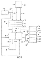
また、光源は、レーザ光が点火サイト28に入るための開口を有する例えば先を切り取った楕円の形である集光装置30、例えば反射体を含むことができる。この集光システムの実施形態に対して以下でより詳細に説明する。集光装置30は、例えば、点火サイト28で第1の焦点、及びEUV光が光源から出力されて例えば集積回路リソグラフィツール(図示せず)に入力されるいわゆる中間点40(中間焦点40とも呼ばれる)で第2の焦点を有する楕円ミラーとすることができる。また、システム20は、ターゲット位置検出システム42を含むことができる。パルスシステム22は、例えば、発振レーザシステム44のためのパルス電力タイミングモニタリングシステム54及び増幅レーザシステム48のためのパルス電力タイミングモニタリングシステム56と共に、発振レーザシステム44のための磁気反応器切換式パルス圧縮及びタイミング回路50と、増幅レーザシステム48のための磁気反応器切換式パルス圧縮及びタイミング回路52とを有する発振レーザシステム44と増幅レーザシステム48とを有する主発振電力増幅器(MOPA)構成2重チャンバガス放電レーザシステムを含むことができる。パルス電力システムは、例えば、YAGレーザからのレーザ出力を作成する電力を含むことができる。また、システム20は、例えば、レーザビーム位置決めシステム66と共に、ターゲット位置検出フィードバックシステム62及び発射制御システム65を含むこともできる。本発明のシステムは、単一の主発振器と協働するいくつかの増幅器も組み込むことができる。
The light source can also include a
ターゲット位置検出システムは、複数の液滴撮像器70、72、74を含むことができ、これは、ターゲット液滴の位置に対して、例えば、発射サイトに対して入力を供給し、かつこれらの入力をターゲット位置検出フィードバックシステムに供給し、これは、例えば、液滴単位でない場合は平均でそこからターゲット誤差を計算することができるターゲット位置及び軌跡を計算することができ、これは、次に、入力としてシステムコントローラ60に供給され、これは、例えば、レーザビーム位置決めシステムが使用して、例えば、レーザ位置及び方向変更器68の位置及び方向を制御し、例えば、レーザビームの焦点位置を異なる点火位置28に変えることができるレーザビーム位置決めシステム66にレーザ位置及び方向補正信号を供給することができる。
The target position detection system may include a plurality of
撮像器72は、例えば、ターゲット液滴94の望ましい軌跡経路に整列した撮像線75に沿ってターゲット送出機構92から望ましい点火サイト28まで向けることができ、撮像器74及び76は、例えば、望ましい点火サイト28の前の経路に沿ったある地点80で、例えば、単独で、望ましい軌跡経路に沿って交差する交差撮像線76及び78に沿って向けることができる。
The
ターゲット送出制御システム90は、システムコントローラ60からの信号に応答して、例えば、ターゲット送出機構92によって放出されるようなターゲット液滴94の放出地点を修正して望ましい点火サイト28に到達するターゲット液滴の誤差を補正することができる。
In response to a signal from the
また、中間焦点40又は中間焦点40近くでのEUV光源検出器100は、例えば、レーザパルスのタイミング及び焦点のような事柄における誤差を示すことができるシステムコントローラ60にフィードバックを行って有効及び効率的なLPP、EUV光生成に適正な場所及び時間においてターゲット液滴を確実に途中で捕捉することができる。
The EUV
ここで図2を参照すると、図1に示すコントローラシステム60及び関連のモニタリング及び制御システム62、64、66の更なる詳細が概略的に示されている。コントローラは、クロックバス115上でシステム構成要素にシステムクロック116によって供給されたシステムクロック信号に相関付けられた例えば複数の位置信号134、軌道信号136をターゲット位置検出フィードバックシステムから受信することができる。コントローラ60は、例えば、システム時間におけるある時点でのターゲットの実位置を計算することができる到着前追跡及びタイミングシステム110と、例えば、何らかのシステム時間でのターゲット液滴の実際の軌道を計算することができるターゲット軌道計算システムと、例えば、点火が発生するように空間及び時間における何らかの望ましい地点と比較して時間的及び空間的誤差信号を計算することができる照射サイト時間的及び空間的誤差計算システム114とを有することができる。
Referring now to FIG. 2, further details of the
次に、コントローラ60は、時間的誤差信号140を発射制御システム64に、空間的誤差信号138をレーザビーム位置決めシステム66に供給することができる。発射制御システムは、発振レーザ44磁気反応器切換式パルス圧縮及びタイミング回路50の共振充電部分118に共振充電開始信号122を供給することができ、かつ例えばPA磁気反応器切換式パルス圧縮及びタイミング回路52の共振充電部分120に共に同じ信号とすることができる共振充電開始信号を供給することができ、かつ発振レーザ44磁気反応器切換式パルス圧縮及びタイミング回路50の圧縮回路部分126にトリガ信号130を、増幅レーザシステム48磁気反応器切換式パルス圧縮及びタイミング回路52の圧縮回路部分128にトリガ信号132を供給することができ、トリガ信号132は、同じ信号ではないとすることができ、かつそれぞれ発振レーザシステム及び増幅レーザシステムに対して時間的誤差信号140から、及び消灯検出装置54及び56からの入力から部分的に計算することができる。Paは、恐らくCW又はCO2レーザとすることができる。
空間誤差信号をレーザビーム位置方向制御システム66に供給することができ、レーザビーム位置方向制御システム66は、例えば、発射地点信号及びサイト信号の線をレーザビーム位置決め装置に供給することができ、レーザビーム位置決め装置は、例えば、発射時の増幅レーザ48の出力の部分の位置及びレーザ出力ビームの照準方向のいずれか又は両方を変えることによって、点火サイト28の焦点を変えるようにレーザを位置決めすることができる。
The spatial error signal can be provided to a laser beam position and
EUV光子エネルギへの駆動レーザ光パルスエネルギの変換に関連する駆動レーザ変換効率(DLCE)、及び駆動レーザパルスを発生する電気エネルギをEUV光エネルギに変換する際の駆動レーザ全体経費を低減するための電気的変換効率(ECE)、並びにEUVシステム経費を含む総変換効率(TCE)を改善するために、本発明の実施形態の態様に従って、本出願人は、同じCO2レーザからの駆動レーザ予備パルス及び駆動レーザ主パルスの両方の発生を提供することを提案する。これはまた、レーザ光集束光学器械寿命及び駆動レーザ光入力窓寿命に有効な影響を与えることができる。 Drive laser conversion efficiency (DLCE) associated with conversion of drive laser light pulse energy to EUV photon energy, and to reduce the overall cost of the drive laser when converting electrical energy generating drive laser pulses into EUV light energy In order to improve electrical conversion efficiency (ECE), as well as total conversion efficiency (TCE) including EUV system costs, in accordance with an aspect of an embodiment of the present invention, Applicants are able to drive laser preliminary pulses from the same CO 2 laser. It is proposed to provide both generation of the driving laser main pulse. This can also have a positive impact on laser beam focusing optics instrument life and drive laser light input window lifetime.
本出願人は、最近、多くの調査、実験、及び分析を通じて、LPP、EUVに対するCO2駆動レーザの使用は、例えば、SnベースのEUV、LPPプラズマ原料物質の場合にある一定の非常に有用な成果を有することができると判断している。一例として、電気エネルギの変換の場合は、比較的高いDLCE及びECE、及び従ってTCE数に達することができる。しかし、CO2駆動レーザのような駆動レーザには、例えば、Nd:YAGレーザ、又はXeFレーザ又はXeClレーザのようなエキシマレーザのような半導体レーザとは対照的に、このような駆動レーザを適切に集束させることはできないというかなり大きな問題がある。10.6μm放射線でのCO2駆動出力パルスは、所要の寸法で緊密に集束させるのは容易なことではない。 Applicant has recently observed through many studies, experiments, and analyzes that the use of a CO2 driven laser for LPP, EUV, for example, some very useful results in the case of Sn-based EUV, LPP plasma source materials. It is judged that it can have. As an example, in the case of electrical energy conversion, relatively high DLCE and ECE, and thus TCE numbers can be reached. However, for a drive laser such as a CO 2 drive laser, such a drive laser is suitable as opposed to a semiconductor laser such as an Nd: YAG laser or an excimer laser such as an XeF laser or an XeCl laser. There is a considerable problem that it cannot be focused on. The CO 2 drive output pulse with 10.6 μm radiation is not easy to focus closely on the required dimensions.
プラズマ形成材料ターゲット液滴94の一般的な大きさは、プラズマ源材料及び恐らく駆動レーザ形式によって約10ミクロンから100ミクロンとすることができ、例えば、デブリ発生及びその後のデブリ管理の観点から一般的に小さいほどよい。目下提案中の集束手法では、例えば、集束レンズ160、及び直径DD(例えば、約50mm)及び焦点距離LL(例えば、約50cm、10.6ミクロンの放射線を例えば液滴範囲の最長端部、例えば、約100ミクロン内にさえも集束させるために)の駆動レーザビーム152を利用する図3に概略的にかつ縮尺通りではなく示すように、レーザの発散は、2*10-4ラジアン未満とすべきである。この値は、1.22*10.6*10-6/50*10-3=2.6*10-4の回折限界よりも小さいものである(例えば、50mmの開口の場合)。従って、所要焦点には到達することができず、例えば、レーザ光エネルギは、ターゲット液滴に入ることにならず、CEは低減される。
The typical size of the plasma-forming
この制限を克服するために、いずれかの焦点距離を短縮すべきであるか、又はレンズ160及びレーザビーム151の直径を大きくすべきである。しかし、これは、EUV集光装置30に大きな中央開口部が必要になり、EUV集光角度が小さくなることから逆効果を招く可能性がある。また、開口部が増大すると、先に参照した現在特許出願中の出願の1つ又はそれよりも多くでより詳細に説明されているように、駆動レーザ送出筐体150によって与えられるデブリ緩和の効果が制限される。特に、このように効果が減少すると、レーザ入力窓の短命化になる可能性がある。
To overcome this limitation, either the focal length should be shortened, or the diameters of the
本発明の実施形態の態様に従って、本出願人は、図4及び図5に概略的にかつ縮尺通りではなく示すように、駆動レーザ放射線の入力の方法及び装置の改良例を提案する。例えば、CO2レーザに対しては、高いNAを有する内部反射光学器械を使用すること、また、例えば、堆積プラズマ開始原料物質、例えば、Snを反射面として使用することを提案する。この集束手法は、2つの反射ミラー170、180を含むことができる。ミラー170は、例えば、モリブデン製の例えば平坦なミラー又は湾曲したミラーとすることができる。最終集束ミラー180は、方向変換ミラー170によって集束ミラー180に方向変換された例えばCO2駆動レーザ入力ビーム172内のCO2放射線を集束させて望ましいプラズマ開始サイト28でターゲット液滴92と交差する集束ビーム176を形成することができる。
In accordance with aspects of embodiments of the present invention, Applicants propose an improved method and apparatus for inputting drive laser radiation, as shown schematically and not to scale in FIGS. For example, for a CO 2 laser, it is proposed to use an internal reflection optical instrument with a high NA and, for example, to use a deposited plasma starting material, eg Sn, as the reflective surface. This focusing technique can include two reflecting
ミラー180の焦点距離は、50cmを大幅に下回る、例えば、5cmとすることができるが、この数字に限定されない。焦点距離がこのように短いミラー180は、例えば、100ミクロン又はそれ未満、特に50μm未満、更に最小約10μmまでの液滴上へのCO2放射線の集束を可能にすることができる。
The focal length of the
本出願人はまた、例えば、加熱器194、例えば、図5に概略的にかつ縮尺通りではなく示す本発明の実施形態の態様によるミラー180’の背後に設置することができるMoリボン加熱器による加熱を用いることを提案する。Sn融点を超えるまでの加熱、及びミラー180’に対しては、例えばLB462という名称である「MCB、Inc.」によって製造されているブラシレス低電圧モータとすることができ、かつプラズマ生成チャンバ26の環境から保護するためにステンレス鋼ケーシング内に封入することができる回転電動機192、及びミラー170’に対しては類似のモータ190を使用した回転を採用することができる。レーザ放射線の反射は、例えば、LPPデブリ堆積によるミラー170、180を被覆するプラズマ原料物質、例えばSnの薄膜からのものになる。必要であれば、回転を用いて、プラズマ原料物質、例えばSnの滑らかな表面を作成することができる。液体Snのこの薄膜は、ミラー170、180のための自己回復反射面を形成することができる。従って、プラズマ原料物質堆積、例えば、ミラー170、180上のSn堆積は、集束光学器械が1つ又はそれよりも多くのレンズの形である場合には、ネガティブではなくプラスとして利用することができる。10.6μm放射線の場合の粗度要件(ラムダ/10)は、容易に達成することができる。ミラー170、180は、モータ192、192で指向及び/又は位置決めすることができる。
Applicants also have, for example, a
液体Snの反射率は、5μmを超える波長に対して実験結果と良好な一致が得られる以下のドルーデの式から推定することができる。
R≒1−2/√(S*T)
ここで、Sは、金属の導電率(CGSシステムにおいて)、Tは、放射線の発振周期である。銅の場合、この式では、10.6μmに対しては約98.5%の反射率の推定値が得られる。Snの場合、反射率推定値は、96%である。
The reflectivity of the liquid Sn can be estimated from the following Drude equation that provides good agreement with the experimental results for wavelengths greater than 5 μm.
R≈1-2 / √ (S * T)
Here, S is the electrical conductivity of the metal (in the CGS system), and T is the radiation oscillation period. In the case of copper, this equation gives an estimate of reflectivity of about 98.5% for 10.6 μm. In the case of Sn, the reflectance estimation value is 96%.
また、放射熱伝達機構を有する回転ミラー180’の背後に設けられた外部加熱器(図示せず)か、又は例えば駆動レーザ光及び/又はプラズマ生成サイト28近傍からの約4%の放射線吸収による自己加熱により、所要の融点を超える図5のミラー180’の加熱を行うことができる。
Also, by an external heater (not shown) provided behind a
図4及び図5で概略的に示すように、レーザ放射線172は、側面ポートを通じてチャンバ内に送出することができ、従って、集光装置30の中央部の過度に大きな開口は不要である。例えば、エキシマレーザDUV範囲においてある一定の波長に有効であるが、CO2のような波長のための集束レンズには有効ではないほぼ同じ大きさの中央開口であれば、本発明の実施形態の態様による集束ミラー構成を利用することができる。更に、チャンバ26の真空封入に利用することができるレーザ入力窓202、及びレーザ送出筐体300は、図3の送出システムにも当て嵌まるように、プラズマ開始サイト及びデブリ発生区域の直接視線内にはない。従って、上述の現在特許出願中の出願の少なくとも1つでより詳細に説明されているような関連の開口及びパージガス及び逆流ガスを備えたレーザ送出筐体の方が、デブリが窓202に到達するのを防止するのに有効である可能性がある。従って、例えば、駆動レーザ送出筐体200の遠位端での図5の実施形態の態様によって示すようなレーザパルス駆動レーザ光の集束が、例えば、CO2駆動レーザの場合の方が比較的大規模である必要があるとしても、照射サイト28から筐体200までのデブリ飛散経路の間接的角度は、遠位端での開口の拡大又は除去を可能にするものであり、一方、図3の実施形態に示す筐体150遠位端での開口の拡大又は除去は、デブリをレンズ160(一部の実施形態では、チャンバ窓の役目をするか、又はチャンバ窓によって置換することができる)に近づけない筐体150の機能に大幅な影響を与える可能性がある。従って、デブリ管理が極めて重要な要素である場合、図4及び図5の構成を利用して、駆動レーザ入力筐体を照射サイト28に至る集束LPP駆動レーザビーム152、176の光軸から離しておくことができる。
As shown schematically in FIGS. 4 and 5, the
本発明の実施形態の態様によれば、例えば、レーザビーム172が外部レンズによって集束されると、焦点近くに位置する駆動レーザ入力筐体円錐部200の広いオリフィスで集束ビームを形成することができる。直接的な集束手法の場合、外部レンズ、例えば、図3のレンズ160がビームを液滴94に集束させる時、円錐部先端は、ある程度の相対距離、例えば、焦点から20mm又は50mm、すなわち、レンズ160の焦点当たりで液滴ターゲット94と交差するようにプラズマ開始サイト28に位置すべきであることになる。それによって、遠位端は、かなりの熱負荷を受ける可能性があり、駆動レーザ電力の本質的に全ては、パルス形成においてターゲットによって吸収され、プラズマ内又はプラズマの周りに放出される。中間焦点を有する本発明の実施形態の態様による光学的構成のこの提案例の場合、円錐部先端は、焦点に(数ミリメートルの距離に)近づけることができるので、円錐部の出力オリフィスは、非常に小さいものとすることができる。それによって、ガス円錐部内のガス圧を大幅に増大させて、他のパラメータ(窓保護効果、チャンバのポンピング速度)を同じに保持しながら、チャンバ内の圧力を低減することができる。反射光学器械は、例えば、CO2レーザに利用することができる。
According to aspects of embodiments of the present invention, for example, when the
ここで図6を参照すると、予備パルス主発振器(MO)252と、主パルス主発振器(MO)254とを含むことができる本発明の実施形態の態様による駆動レーザシステム250、例えば、CO2駆動レーザが概略的にかつブロック図の形で示されており、主発振器の各々は、波長が約10.6μmのシードレーザパルスを電力増幅器(PA)272に供給するCO2ガス放電レーザ又は他の適切なシードレーザとすることができ、電力増幅器は、約10.6μmでレーザを出射する単一パス又は多重パスCO2ガス放電レーザとすることができる。MO252出力は、主パルスのパルスエネルギの約1%から10%のパルスエネルギを有する予備パルスを形成することができ、MO254出力は、約1x10¹⁰ワット/平方センチメートルのパルスエネルギを有する主パルスを形成することができ、同じか又は異なるとすることができる波長を有する。
Referring now to FIG. 6, a
MO255からの出力パルスは、例えば、ミラー260によって偏光ビームスプリッタ262に反射させることができ、また、偏光ビームスプリッタ262は、PA272内で増幅されるシードパルスとして第1の選択極性を有する光の全て又は本質的に全てを反射させる。第2の選択極性を有するMO252出力は、偏光ビームスプリッタ262を通過して、別のシードパルスとしてPA272内に入ることができる。従って、MO252及びMO254の出力は、MO252の予備パルス部分とMO254からの主パルス部分とを有する結合シードパルス270に形成することができる。
The output pulse from the MO 255 can be reflected, for example, by the
結合パルス270は、MOPAガス放電レーザの技術分野で公知のように、MO252、254とPAとの間の適切なタイミングで「XLA 100」及び「XLA 200」シリーズMOPAレーザシステムのような本出願人の譲渡人によって販売されているようなパルス電力送出モジュールでPA272内で増幅され、結合パルス270が駆動レーザ出力パルス274を形成するように増幅される時にPA内の増幅レーザ媒質の存在を保証することができる。MO254及びMO252の発射のタイミングは、例えば、ガス放電が例えばMO252発射の後であるがMO252の発射の約数ナノ秒以内に開始されるように、例えば、MO254が時間的に遅く発射されるように、予備パルスが結合シードパルス270内では主パルスよりも若干先行するようなものである。また、予備パルス及び主パルスの性質、例えば、相対強度、ピーク分離、絶対強度などは、パルス生成における望ましい効果から決定され、かつある一定の要素、例えば、駆動レーザの形式及び例えば波長、ターゲット材料の形式、及び例えばターゲット液滴サイズなどに関連することが当業者によって理解されるであろう。
The combined
ここで図7を参照すると、図6を参照して上述したように、PA272内での増幅に向けて結合パルス270を形成するために、最初に予備パルス、次に主パルスを共振器内で発生させるのに有用なQスイッチ284が共振器内において共振器後部ミラー282と出力結合器286との中間にある例えば共振器後部ミラー282と出力結合器286とを有するレーザ発振空洞によって形成された例えばMO利得発生器280を含む駆動レーザシステム250、例えば、CO2駆動レーザシステムを含むことができる本発明の実施形態の態様が概略ブロック図の形で示されている。
Referring now to FIG. 7, as described above with reference to FIG. 6, in order to form the combined
ここで図8を参照すると、約18kHz程度及び更にそれを超える出力パルス繰返し数での作動が可能であるCO2ガス放電レーザシステムのような多重電力増幅高繰返し数駆動レーザシステム300が示されている。図8のシステム250は、例えば、主発振器290と、直列の複数の例えば3つのPA310、312、及び314を含むことができる。PA310、312、及び314の各々には、それぞれのパルス電力システム322、324、及び326からのガス放電電気エネルギを供給することができ、パルス電力システムの各々は、当業者によって理解されるように、単一の高電圧電源によって(あるいは、別々のそれぞれの高電圧電源により)初めに充電することができる。
Referring now to FIG. 8, there is shown a multiple power amplified high repetition rate drive laser system 300 such as a CO 2 gas discharge laser system capable of operating at an output pulse repetition rate of about 18 kHz and beyond. Yes. The
図9を参照すると、結果的にPAの数のX倍の出力パルス繰返し数、例えば、図8の例示的な例においてはx*3、すなわち、各々が6kHzで作動する3つのPAの場合に18kHzを得ることができる発射図292が示されている。すなわち、MOは、MO出力パルス発射タイミングマーク294によって表示される割合でエネルギが比較的低いシードパルスを発生し、一方、それぞれのPAの発射は、タイミング図によって示すように、PA310、312、及び314の連続的なPAにおいてMO出力パルスが連続的に増幅されるように、発射タイミングマーク296によって表示される交互方式にすることができる。また、MO290及び各それぞれのPA310、3412、314のそれぞれの発射間のタイミングは、MOからのそれぞれの出力パルスがそれぞれのPA310、312、314内で増幅が発生するように、例えば、このようなPA310、312、314内の電極間のガス放電によってそれぞれのPA310、312、314内で増幅を発生させることができる光路全体における位置に到達することを可能にするように調整する必要があることになることが、当業者によって理解されるであろう。
Referring to FIG. 9, the result is an output pulse repetition rate that is X times the number of PAs, eg, x * 3 in the illustrative example of FIG. 8, ie, three PAs each operating at 6 kHz. A firing diagram 292 that can obtain 18 kHz is shown. That is, the MO generates seed pulses with relatively low energy at the rate indicated by the MO output pulse firing timing mark 294, while each PA firing is represented by the
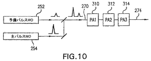
ここで図10及び図11を参照すると、本発明の実施形態の態様によれば、駆動レーザシステム、例えば、図6及び図7の実施形態の特徴を兼ね備えたCO2駆動レーザシステムを利用して、例えば、上述のように結合パルス270を生成し、ここでもまた上述のように交互方式で選択PA310、312、314内でそれらの各々を増幅することにより、結合予備パルス及び主パルスでより高い繰返し数の出力レーザパルス274を作成することができる。
Referring now to FIGS. 10 and 11, according to aspects of embodiments of the present invention, a drive laser system is utilized, for example, a CO 2 drive laser system that combines the features of the embodiments of FIGS. For example, by generating combined
上述のシステム250は、2つのMO(予備パルスと主パルス)及び単一のPA(単一パス又は多重パス)とを有するCO2LPP駆動レーザを含むことができ、両方のMOからのビームは、単一ビームに結合され、これは、PAによって増幅され、又は共振空洞内のQスイッチングによって形成された結合ビーム、及びそのように生成された結合予備パルス及び主パルスビームは、次に、例えば、結合パルスを発生するMOと同じパルス繰返し数で作動する単一のPAにおいて、又はxをPAの数とし、PAが交互方式で連続して発射されるとして、パルス繰返し数i/xに結合パルス生成MOのパルス繰返し数を乗じたもので作動する一連のPAによって増幅することができることが当業者によって理解されるであろう。それぞれのMOからの2本のビームの結合は、偏光によって又はビーム分離器を使用することによって行われ、MO経路の一方、例えば、予備パルスMO経路内の損失を被る可能性がある。また、例えば、CO2レーザの低い利得のために、結合パルス内に含まれた予備パルス及び主パルスの両方を増幅する同じPAを同時に共有することが理解されるであろう。これは、ある一定の形式のレーザ、例えば、CO2レーザの場合は固有のものであり、利得が遥かに大きい及び/又は飽和しやすいために他のレーザ、例えば、エキシマレーザでは不可能であろう。
The
ここで図12を参照すると、本発明の更に別の実施形態の態様の図が概略的に示されている。この実施形態は、駆動レーザ入力窓330を通じて入る集束駆動レーザビーム342が通過することができる駆動レーザ送出筐体を有することができる。駆動レーザビーム342は、集束された後に拡張ビーム344を形成し、次に、例えば、平坦な指向ミラー340によって操作することができ、ビーム344及びミラー340及び集束駆動レーザビームの焦点の大きさは、EUV生成プラズマを形成するようにターゲット液滴の照射に向けてビーム346が集光装置の焦点28に再度集束されるように指向ビーム346が集光装置30の中央部を照射するようなものである。ミラー340は、上述のように、回転モータ360によって回転させることができる。集光装置30の中央部350は、駆動レーザのDUV範囲において反射性である材料、例えば、XeFレーザガスの場合は351nmが得られるように適切な反射コーティングを有するCaF2、又はCO2レーザの場合には約10μmの波長で反射性の材料で形成することができる。
Referring now to FIG. 12, a diagram of an aspect of yet another embodiment of the present invention is shown schematically. This embodiment can have a drive laser delivery housing through which a focused
当業者は、駆動レーザビームを生成する駆動レーザと、第1の軸線を有する駆動レーザビーム第1経路と、第1経路から第2の軸線を有する第2経路にシステムレーザビームを移送する駆動レーザ方向変換機構と、十分に大きな、例えば数ステラジアンの開口部と共に、中央に位置する開口、すなわち、必ずしも集光装置光学要素に関連したものであるとは限らない他の光学要素を設置することができる開口部を有するEUV集光装置光学要素、すなわち、駆動レーザ光と共に照射された時にプラズマ内に生成されたEUV光を有効に集束させる集束ミラー光学器械とを含むことができるレーザ生成プラズマEUVシステムを含むことができる装置及び方法が以上の本明細書で説明されていることを認めるであろう。この装置及び方法は、更に、第2経路内にあり、開口内に位置決めされ、かつ第2の軸線に沿って位置するプラズマ開始サイト上にシステムレーザビームを集束させる集束ミラーを含むことができる。また、先に参照した現在特許出願中の出願の1つ又はそれよりも多くにおいてより詳細に説明されているように、パルス開始は、例えば、正確にEUV集束光学器械の焦点での理想的なサイトにあると考えることができることも理解されるであろう。しかし、いくつかの要因のために、時々及び恐らくは殆どの場合、実際のプラズマ開始サイトは、理想的なプラズマ開始サイトから外れている場合があるので、制御システムを利用して、レーザ/ターゲット交差及び実際のプラズマ開始サイトを理想的なサイトに移動して戻すように駆動レーザビーム及び/又はターゲット送出システムに指令することができる。従って、プラズマ開始サイトの概念は、特許請求の範囲を含む本明細書で使用される時、比較的固定されたままである望ましい又は理想的なプラズマ開始サイトのこの概念が組み込まれているが(それは、例えば、多くのkHzのパルス繰返し数と比較すると比較的緩やかな時間的尺度にわたって変化する可能性もある)、作動的に及び/又は制御システムのずれなどのために、実際のプラズマ開始サイトは、制御システムが、誤った位置であるが依然として全体的に最適化された集光に対して理想的又は望ましいサイトの付近にあるサイトから例えば焦点での望ましい/理想的な位置までプラズマ開始サイトを移動させるので、時間的に変動する多くの場所に位置することができる。 Those skilled in the art will recognize a drive laser that generates a drive laser beam, a drive laser beam first path having a first axis, and a drive laser that transfers the system laser beam from the first path to a second path having a second axis. A direction change mechanism and a sufficiently large opening, for example several steradians, together with a centrally located opening, i.e. other optical elements not necessarily associated with the concentrator optical element A laser-produced plasma EUV system that can include an EUV concentrator optical element having an aperture capable of focusing, ie, a focusing mirror optical instrument that effectively focuses the EUV light generated in the plasma when illuminated with drive laser light It will be appreciated that apparatus and methods that can be included are described herein above. The apparatus and method may further include a focusing mirror that focuses the system laser beam onto a plasma initiation site that is in the second path, positioned in the aperture, and located along the second axis. Also, as described in more detail in one or more of the above-referenced current patent-pending applications, pulse initiation is ideally suited, for example, at the focal point of an EUV focusing optical instrument. It will also be understood that it can be considered to be on the site. However, due to several factors, sometimes and perhaps most of the time, the actual plasma start site may be off the ideal plasma start site, so a control system is used to make the laser / target crossover. And the driving laser beam and / or target delivery system can be commanded to move the actual plasma start site back to the ideal site. Thus, the concept of plasma initiation site incorporates this concept of a desirable or ideal plasma initiation site that remains relatively fixed as used herein, including the claims. (E.g., it may vary over a relatively gradual time scale compared to many kHz pulse repetition rates), due to operational and / or control system drift, etc. The control system moves the plasma start site from a site in the vicinity of the ideal or desired site to the desired / ideal location at the focal point, for example, in the wrong position but still totally optimized. Since it is moved, it can be located in many places that vary with time.
本発明の装置及び方法は、幾何学形状の制限において実際的ではない場合に有効プラズマ生成エネルギで約100μm未満のEUVターゲット液滴上に集束させるのに集束レンズを利用することを必要とするような波長を有する駆動レーザによって生成されることを含むことができる。上述のように、これは、例えばCO2レーザの特性であるが、CO2レーザは、このある一定の種類の非有効性を発生する唯一の駆動レーザではないであろう。駆動レーザ方向変換機構は、ミラーを含むことができる。この集束ミラーは、開口の外側にある集光装置光学要素から、プラズマ開始サイトに発生したプラズマ内に生成されたEUV光を遮断するように位置決めされ、かつそのような大きさにすることができる。 The apparatus and method of the present invention will require the use of a focusing lens to focus on EUV target droplets of less than about 100 μm with effective plasma generation energy when impractical in geometric constraints. Can be generated by a drive laser having a different wavelength. As noted above, this is a characteristic of, for example, a CO 2 laser, but a CO 2 laser may not be the only drive laser that produces this certain type of ineffectiveness. The drive laser direction changing mechanism may include a mirror. The focusing mirror is positioned and can be sized to block EUV light generated in the plasma generated at the plasma start site from the collector optical elements outside the aperture. .
上述のように、この利点は、他の有用なかつ望ましい属性を有することができるCO2レーザのような駆動レーザの使用を可能にすることができるが、一般的に、本発明の実施形態の態様による上述のミラー集束要素によって占有された大きさと類似の大きさの集光装置開口に入るビームに対しては集束レンズによる集束には不適である。 As mentioned above, this advantage can allow the use of a drive laser, such as a CO 2 laser, that can have other useful and desirable attributes, but in general, aspects of embodiments of the present invention Is not suitable for focusing by a focusing lens for a beam that enters a concentrator aperture of a size similar to that occupied by the mirror focusing element described above.
方向変換機構は、回転させることができ、かつ集束ミラーは、加熱することができる。本発明の装置及び方法は、更に、予備パルス部分及び主パルス部分を有する結合出力パルスを発生するシードレーザシステムと、予備パルス部分と主パルス部分とを同時に増幅し、予備パルス部分が増幅レーザの利得を飽和させることのない増幅レーザとを含むことができる。予備パルス及び主パルスの各々自体は、それ自体が「パルス」であると考えることができる時間的長さにわたっていくつかのピークを有するパルスで形成することができることが当業者によって理解されるであろう。本明細書及び特許請求の範囲で使用する予備パルスは、主パルスよりも小さい強度(例えば、ピーク及び/又は積分)を有し、かつ例えばプラズマ原料物質でのプラズマ形成を開始し、次に、駆動レーザエネルギのより大きな入力によりプラズマ上への主パルスの集束を通じてプラズマを形成するのに有用なパルスを意味するように意図されている。これは、形状、持続時間、主パルスの予備パルスにおける「ピーク」/「パルス」の数、又はシードパルス発生器の出力部で又は結合パルス内で予備パルス部分及び主パルス部分において1つよりも多いパルスを形成する時に見ることができる大きさ、形状、時間的持続時間などの他の特性に関係がないものである。 The direction changing mechanism can be rotated and the focusing mirror can be heated. The apparatus and method of the present invention further includes a seed laser system that generates a combined output pulse having a prepulse portion and a main pulse portion, and simultaneously amplifying the prepulse portion and the main pulse portion, wherein the prepulse portion is an amplified laser. And an amplifying laser that does not saturate the gain. It will be appreciated by those skilled in the art that each of the pre-pulse and the main pulse can itself be formed of a pulse having several peaks over a length of time that can be considered to be a “pulse” itself. Let's go. The preliminary pulse used herein and in the claims has a smaller intensity (eg, peak and / or integral) than the main pulse and initiates plasma formation, eg, with the plasma source material, and then It is intended to mean a pulse useful for forming a plasma through focusing of the main pulse onto the plasma with a greater input of drive laser energy. This is because the shape, duration, number of “peaks” / “pulses” in the prepulse of the main pulse, or more than one in the prepulse and main pulse portions at the output of the seed pulse generator or within the combined pulse. It is unrelated to other properties such as size, shape, and time duration that can be seen when creating many pulses.
増幅レーザは、CO2レーザを含むことができる。結合パルスの予備パルス部分は、第1のシードレーザで生成することができ、結合パルスの主パルス部分は、第2シードレーザで生成することができ、又は結合パルスの予備パルス部分及び主パルス部分は、単一のシードレーザで生成することができる。本発明の装置及び方法は、更に、少なくとも12kHz、例えば18kHzのパルス繰返し数Xでシードレーザパルスを発生するシードレーザと、例えば各々がX/N、3つのPAの場合は6kHz、合計で18kHzになる割合で発射される複数のN個の増幅レーザとを含むことができ、3つのPAは、シードレーザパルスの光路内に直列に位置決めすることができ、各々は、交互方式のタイミングでX/Nのパルス繰返し数でそれぞれのN番目のシードパルスを増幅する。各々のそれぞれの増幅レーザは、シード生成レーザのそれぞれのN番目の出力がそれぞれの増幅レーザ内にあるようにシード生成レーザの発射に合わせて発射することができる。シードレーザパルスは、予備パルス部分と主パルス部分とを含むことができる。 The amplification laser can include a CO 2 laser. The preliminary pulse portion of the combined pulse can be generated with the first seed laser, the main pulse portion of the combined pulse can be generated with the second seed laser, or the preliminary pulse portion and the main pulse portion of the combined pulse Can be generated with a single seed laser. The apparatus and method of the present invention further includes a seed laser that generates seed laser pulses at a pulse repetition rate X of at least 12 kHz, for example 18 kHz, for example, X / N for each of three PAs, 6 kHz for a total of 18 kHz. A plurality of N amplifying lasers that are fired at a ratio, and the three PAs can be positioned in series in the optical path of the seed laser pulse, each of which is X / Each Nth seed pulse is amplified with N pulse repetitions. Each respective amplifying laser can be fired with the firing of the seed generating laser such that the respective Nth output of the seed generating laser is within the respective amplifying laser. The seed laser pulse can include a preliminary pulse portion and a main pulse portion.
「35U.S.C.§112」を満足するために必要とされる詳細において本特許出願において説明しかつ例示した「LPP、EUV光源駆動レーザシステム」の実施形態の特定の態様は、上述の実施形態の態様のあらゆる上述の目的、及び上述の実施形態の態様により又はその目的のあらゆる他の理由で又はその目的にために解決すべき問題を完全に達成することができるが、本発明の上述の実施形態のここで説明した態様は、本発明による広義の主題を示しかつ表すことを当業者は理解すべきである。実施形態のここで説明しかつ主張する態様の範囲は、本明細書の教示内容に基づいて当業者に現在明らかであると考えられるか又は明らかになると考えられる他の実施形態を漏れなく包含するものである。本発明の「LPP、EUV光源駆動レーザシステム」の範囲は、単独にかつ完全に特許請求の範囲によってのみ限定され、いかなるものも特許請求の範囲の詳細説明を超えるものではない。単数形でのこのような請求項における要素への言及は、解釈において、明示的に説明していない限り、このような要素が「1つ及び1つのみ」であることを意味するように意図しておらず、かつ意味しないものとし、「1つ又はそれよりも多い」を意味する意図とし、かつ意味するものとする。当業者に公知か又は後で公知になる実施形態の上述の態様の要素のいずれかに対する全ての構造的及び機能的均等物は、引用により本明細書に明示的に組み込まれると共に、特許請求の範囲によって包含されるように意図されている。本明細書及び/又は本出願の請求項に使用され、かつ本明細書及び/又は本出願の請求項に明示的に意味を与えられたあらゆる用語は、このような用語に関するあらゆる辞書上の意味又は他の一般的に使用される意味によらず、その意味を有するものとする。実施形態のいずれかの態様として本明細書で説明した装置又は方法は、それが特許請求の範囲によって包含されるように本出願において開示する実施形態の態様によって解決するように求められる各及び全て問題に対処することを意図しておらず、また必要でもない。本発明の開示内容におけるいかなる要素、構成要素、又は方法段階も、その要素、構成要素、又は方法段階が特許請求の範囲において明示的に詳細に説明されているか否かに関係なく、一般大衆に捧げられることを意図したものではない。特許請求の範囲におけるいかなる請求項の要素も、その要素が「〜のための手段」という語句を使用して明示的に列挙されるか又は方法の請求項の場合にはその要素が「作用」ではなく「段階」として列挙されていない限り、「35U.S.C.§112」第6項の規定に基づいて解釈されないものとする。 Certain aspects of the “LPP, EUV light source driven laser system” embodiment described and illustrated in this patent application in the details required to satisfy “35 USC §112” are described above. Any of the above-mentioned objects of the aspects of the embodiments, and the problems to be solved by or for any other reason of the objects of the above-mentioned embodiments can be completely achieved. It should be understood by those skilled in the art that the aspects described herein of the above-described embodiments illustrate and represent the broad subject matter according to the present invention. The scope of the presently described and claimed aspects of the embodiments encompasses all other embodiments that are presently believed or will be apparent to those of ordinary skill in the art based on the teachings herein. Is. The scope of the “LPP, EUV light source driven laser system” of the present invention is limited solely and completely by the claims, and nothing in any way exceeds the detailed description of the claims. References to elements in such claims in the singular are intended to mean that such elements are "one and only one" unless explicitly stated in the interpretation. Not intended and meaningless, and intended and meant to mean "one or more". All structural and functional equivalents of any of the above-described aspects of embodiments known to those skilled in the art or later known are expressly incorporated herein by reference and are It is intended to be covered by a range. Any term used in the specification and / or claims of this application and expressly given meaning to this specification and / or claims of this application shall have any dictionary meaning for such terms. Or shall have its meaning regardless of other commonly used meanings. Each or all of the apparatus or methods described herein as any aspect of an embodiment is sought to be solved by the aspects of the embodiment disclosed in this application, as it is encompassed by the claims. It is not intended or necessary to deal with the problem. Any element, component, or method step in the disclosure of the present invention will be disclosed to the general public regardless of whether the element, component, or method step is explicitly described in detail in the claims. It is not intended to be dedicated. Any claim element in a claim is either explicitly recited using the phrase “means for” or the element is “action” in the case of a method claim. However, unless it is listed as “stage”, it shall not be construed in accordance with the provisions of paragraph 6 of “35 USC § 112”.
上記で開示した本発明の実施形態の態様は、好ましい実施形態であることのみを意図しており、いかなる点においても本発明の開示内容を限定するものではなく、特に、特定の好ましい実施形態だけに限定するものではないものとすることが当業者によって理解されるであろう。開示した発明の実施形態の開示した態様には、当業者によって理解及び認められるような多くの変更及び修正を行うことができる。特許請求の範囲は、その範囲及び意味において、本発明の実施形態の開示した態様だけではなく、当業者には明らかになると思われる均等物及び他の修正及び変更も包含するものとする。上述の本発明の実施形態の開示して請求した態様に対する変更及び修正に加えて、以下も実施することができると考えられる。 Aspects of the embodiments of the invention disclosed above are intended to be preferred embodiments only and are not intended to limit the disclosure of the invention in any way, in particular only certain preferred embodiments. It will be understood by those skilled in the art that the present invention is not intended to be limiting. Many changes and modifications may be made to the disclosed aspects of embodiments of the disclosed invention as will be understood and appreciated by those skilled in the art. The claims are intended to encompass, within its scope and meaning, not only the disclosed aspects of the embodiments of the present invention, but also equivalents and other modifications and changes that would be apparent to a person skilled in the art. In addition to the changes and modifications to the disclosed and claimed aspects of the embodiments of the invention described above, it is contemplated that the following may also be implemented.
40 中間焦点
172 レーザ放射線
176 集束ビーム
180 集束ミラー
40
Claims (5)
照射サイトにおいて前記レーザビームと相互作用してEUV光放射プラズマを生成するための材料であって、当該プラズマによって生成されるデブリが錫を含むように、錫が含まれた材料と、
前記材料が前記レーザビームと相互作用するように、前記材料を、液滴、固体粒子、又は液滴内に含まれた固体粒子の形のターゲットとして前記照射サイトに落下により送出するターゲット送出装置と、
前記錫が含まれるデブリにさらされる反射光学部品であって、前記レーザビームを前記照射サイトに向けて反射する反射光学部品と、
前記照射サイトにおいて発生したEUV光を反射して焦点に集光する反射集光装置と、
レーザ入力窓を有する容器と、を含み、
前記照射サイトは前記容器の中にあり、前記反射光学部品は前記容器の内部に配置されており、かつ、前記レーザ入力窓は到達する錫を含む前記デブリが少なくなるように前記反射光学部品と前記照射サイトとを結ぶ軸から離して設けられており、
さらに、前記レーザ入力窓を保護する円錐形状の筐体を有する、
ことを特徴とするEUV光源。 A laser device for outputting a laser beam having a wavelength longer than 5 μm;
A material for interacting with the laser beam at an irradiation site to generate EUV radiation plasma, the material containing tin such that debris generated by the plasma contains tin;
A target delivery device for delivering the material by dropping to the irradiation site as a target in the form of a droplet, solid particles, or solid particles contained within the droplet, such that the material interacts with the laser beam; ,
A reflective optical component exposed to debris containing tin, the reflective optical component reflecting the laser beam toward the irradiation site;
A reflective condensing device that reflects EUV light generated at the irradiation site and collects it at a focal point;
A container having a laser input window,
The irradiation site is in the container, the reflective optical component is disposed inside the container, and the laser input window is arranged to reduce the debris containing tin that reaches the reflective optical component. provided apart from the axis connecting the said irradiation site,
Furthermore, it has a conical housing that protects the laser input window,
An EUV light source characterized by that.
レーザビームを出力するレーザ装置と、
前記レーザビームを反射し、反射したレーザビームを前記EUV光源の軸上の焦点位置に集束するよう配置された反射光学器械と、
前記焦点位置において前記レーザビームと相互作用してEUV光放射プラズマを生成する材料と、
前記材料が前記レーザビームと相互作用するように、前記材料を、液滴、固体粒子、又は液滴内に含まれた固体粒子の形のターゲットとして前記焦点位置に落下により送出するターゲット送出装置と、
レーザ入力窓を有する容器と、ここで、前記レーザ入力窓は、容器外部の前記レーザ装置からの前記レーザビームを前記反射光学器械に入力し、
前記焦点位置において発生したEUV光を反射して前記焦点位置とは異なる焦点に集光する反射集光装置と、
を含み、
前記焦点位置は前記容器の中にあり、前記反射光学器械は前記容器の内部に配置されており、かつ、前記レーザ入力窓は到達するデブリが少なくなるように前記反射集光装置の軸から離して設けられており、さらに前記レーザ入力窓から入力された前記レーザビームは前記反射光学器械によって当該レーザビームの伝播する前記軸上の焦点に集光される、
ことを特徴とするEUV光源。 An EUV light source,
A laser device for outputting a laser beam;
Reflecting the laser beam, and arranged reflecting optics to focus the reflected laser beam at the focal point on the axis of the EUV light source,
A material that interacts with the laser beam at the focal position to generate EUV radiation plasma;
A target delivery device for dropping the material as a target in the form of a droplet, a solid particle, or a solid particle contained within the droplet by drop to the focal position so that the material interacts with the laser beam; ,
A container having a laser input window, wherein the laser input window inputs the laser beam from the laser device outside the container to the reflective optical instrument;
A reflective condensing device that reflects EUV light generated at the focal position and collects it at a focal point different from the focal position;
Including
The focal position is in the container, the reflective optics is located inside the container, and the laser input window is spaced from the axis of the reflective concentrator so that less debris reaches it. Further, the laser beam input from the laser input window is condensed at the focal point on the axis on which the laser beam propagates by the reflection optical instrument.
An EUV light source characterized by that.
Applications Claiming Priority (5)
| Application Number | Priority Date | Filing Date | Title |
|---|---|---|---|
| US11/174,299 US7439530B2 (en) | 2005-06-29 | 2005-06-29 | LPP EUV light source drive laser system |
| US11/174,299 | 2005-06-29 | ||
| US11/217,161 | 2005-08-31 | ||
| US11/217,161 US7482609B2 (en) | 2005-02-28 | 2005-08-31 | LPP EUV light source drive laser system |
| PCT/US2006/024960 WO2007005415A2 (en) | 2005-06-29 | 2006-06-27 | Lpp euv light source drive laser system |
Related Child Applications (1)
| Application Number | Title | Priority Date | Filing Date |
|---|---|---|---|
| JP2014084934A Division JP2014160670A (en) | 2005-06-29 | 2014-04-16 | Lpp euv light source drive laser system |
Publications (3)
| Publication Number | Publication Date |
|---|---|
| JP2009500796A JP2009500796A (en) | 2009-01-08 |
| JP2009500796A5 JP2009500796A5 (en) | 2009-08-13 |
| JP5597885B2 true JP5597885B2 (en) | 2014-10-01 |
Family
ID=37588366
Family Applications (1)
| Application Number | Title | Priority Date | Filing Date |
|---|---|---|---|
| JP2008519481A Active JP5597885B2 (en) | 2005-06-29 | 2006-06-27 | LPP, EUV light source drive laser system |
Country Status (2)
| Country | Link |
|---|---|
| US (3) | US7439530B2 (en) |
| JP (1) | JP5597885B2 (en) |
Families Citing this family (89)
| Publication number | Priority date | Publication date | Assignee | Title |
|---|---|---|---|---|
| US7856044B2 (en) | 1999-05-10 | 2010-12-21 | Cymer, Inc. | Extendable electrode for gas discharge laser |
| US7843632B2 (en) * | 2006-08-16 | 2010-11-30 | Cymer, Inc. | EUV optics |
| US7476886B2 (en) * | 2006-08-25 | 2009-01-13 | Cymer, Inc. | Source material collection unit for a laser produced plasma EUV light source |
| US7916388B2 (en) * | 2007-12-20 | 2011-03-29 | Cymer, Inc. | Drive laser for EUV light source |
| US7897947B2 (en) * | 2007-07-13 | 2011-03-01 | Cymer, Inc. | Laser produced plasma EUV light source having a droplet stream produced using a modulated disturbance wave |
| US7928416B2 (en) * | 2006-12-22 | 2011-04-19 | Cymer, Inc. | Laser produced plasma EUV light source |
| US7491954B2 (en) * | 2006-10-13 | 2009-02-17 | Cymer, Inc. | Drive laser delivery systems for EUV light source |
| US7439530B2 (en) * | 2005-06-29 | 2008-10-21 | Cymer, Inc. | LPP EUV light source drive laser system |
| US8653437B2 (en) | 2010-10-04 | 2014-02-18 | Cymer, Llc | EUV light source with subsystem(s) for maintaining LPP drive laser output during EUV non-output periods |
| US7671349B2 (en) | 2003-04-08 | 2010-03-02 | Cymer, Inc. | Laser produced plasma EUV light source |
| US8654438B2 (en) * | 2010-06-24 | 2014-02-18 | Cymer, Llc | Master oscillator-power amplifier drive laser with pre-pulse for EUV light source |
| ATE430369T1 (en) * | 2005-11-02 | 2009-05-15 | Univ Dublin | MIRROR FOR HIGH POWER EUV LAMP SYSTEM |
| JP5156192B2 (en) * | 2006-01-24 | 2013-03-06 | ギガフォトン株式会社 | Extreme ultraviolet light source device |
| US8158960B2 (en) | 2007-07-13 | 2012-04-17 | Cymer, Inc. | Laser produced plasma EUV light source |
| US8513629B2 (en) | 2011-05-13 | 2013-08-20 | Cymer, Llc | Droplet generator with actuator induced nozzle cleaning |
| US8525138B2 (en) | 2006-03-31 | 2013-09-03 | Energetiq Technology, Inc. | Laser-driven light source |
| JP4884152B2 (en) * | 2006-09-27 | 2012-02-29 | 株式会社小松製作所 | Extreme ultraviolet light source device |
| JP5358060B2 (en) * | 2007-02-20 | 2013-12-04 | ギガフォトン株式会社 | Extreme ultraviolet light source device |
| JP5277496B2 (en) * | 2007-04-27 | 2013-08-28 | ギガフォトン株式会社 | Extreme ultraviolet light source device and optical element contamination prevention device of extreme ultraviolet light source device |
| US7655925B2 (en) * | 2007-08-31 | 2010-02-02 | Cymer, Inc. | Gas management system for a laser-produced-plasma EUV light source |
| US7812329B2 (en) * | 2007-12-14 | 2010-10-12 | Cymer, Inc. | System managing gas flow between chambers of an extreme ultraviolet (EUV) photolithography apparatus |
| JP2009246345A (en) * | 2008-03-12 | 2009-10-22 | Komatsu Ltd | Laser system |
| US7872245B2 (en) * | 2008-03-17 | 2011-01-18 | Cymer, Inc. | Systems and methods for target material delivery in a laser produced plasma EUV light source |
| NL1036614A1 (en) * | 2008-03-21 | 2009-09-22 | Asml Netherlands Bv | A target material, a source, an EUV lithographic apparatus and a device manufacturing method using the same. |
| US20090250637A1 (en) * | 2008-04-02 | 2009-10-08 | Cymer, Inc. | System and methods for filtering out-of-band radiation in EUV exposure tools |
| US8227778B2 (en) | 2008-05-20 | 2012-07-24 | Komatsu Ltd. | Semiconductor exposure device using extreme ultra violet radiation |
| JP5061063B2 (en) * | 2008-05-20 | 2012-10-31 | ギガフォトン株式会社 | Extreme ultraviolet light mirror and extreme ultraviolet light source device |
| NL2002890A1 (en) * | 2008-06-16 | 2009-12-17 | Asml Netherlands Bv | Lithographic apparatus. |
| US8198612B2 (en) * | 2008-07-31 | 2012-06-12 | Cymer, Inc. | Systems and methods for heating an EUV collector mirror |
| US8519366B2 (en) | 2008-08-06 | 2013-08-27 | Cymer, Inc. | Debris protection system having a magnetic field for an EUV light source |
| JP5454881B2 (en) * | 2008-08-29 | 2014-03-26 | ギガフォトン株式会社 | Extreme ultraviolet light source device and method for generating extreme ultraviolet light |
| US7641349B1 (en) | 2008-09-22 | 2010-01-05 | Cymer, Inc. | Systems and methods for collector mirror temperature control using direct contact heat transfer |
| JP5587578B2 (en) | 2008-09-26 | 2014-09-10 | ギガフォトン株式会社 | Extreme ultraviolet light source device and pulse laser device |
| JP5536401B2 (en) * | 2008-10-16 | 2014-07-02 | ギガフォトン株式会社 | Laser device and extreme ultraviolet light source device |
| US8283643B2 (en) * | 2008-11-24 | 2012-10-09 | Cymer, Inc. | Systems and methods for drive laser beam delivery in an EUV light source |
| KR101278425B1 (en) * | 2008-12-27 | 2013-06-24 | 에너제틱 테크놀로지 아이엔씨. | Light source apparatus |
| TWI457715B (en) * | 2008-12-27 | 2014-10-21 | Ushio Electric Inc | Light source device |
| JP5474576B2 (en) * | 2009-01-14 | 2014-04-16 | ギガフォトン株式会社 | LASER OPTICAL AMPLIFIER AND LASER DEVICE USING THE SAME |
| JP5619779B2 (en) * | 2009-02-13 | 2014-11-05 | ケーエルエー−テンカー コーポレイション | Optical pumping to sustain high temperature plasma |
| US8969838B2 (en) * | 2009-04-09 | 2015-03-03 | Asml Netherlands B.V. | Systems and methods for protecting an EUV light source chamber from high pressure source material leaks |
| US8304752B2 (en) * | 2009-04-10 | 2012-11-06 | Cymer, Inc. | EUV light producing system and method utilizing an alignment laser |
| JP5612579B2 (en) * | 2009-07-29 | 2014-10-22 | ギガフォトン株式会社 | Extreme ultraviolet light source device, control method of extreme ultraviolet light source device, and recording medium recording the program |
| DE102009047712A1 (en) * | 2009-12-09 | 2011-06-16 | Carl Zeiss Smt Gmbh | EUV light source for a lighting device of a microlithographic projection exposure apparatus |
| JP2011192961A (en) * | 2010-02-19 | 2011-09-29 | Komatsu Ltd | Laser device, extreme ultraviolet light generation device, and method for maintaining the devices |
| JP5687488B2 (en) | 2010-02-22 | 2015-03-18 | ギガフォトン株式会社 | Extreme ultraviolet light generator |
| JP5093267B2 (en) * | 2010-03-11 | 2012-12-12 | ウシオ電機株式会社 | Condensing mirror assembly and extreme ultraviolet light source device using the condensing mirror assembly |
| JP5666285B2 (en) | 2010-03-15 | 2015-02-12 | ギガフォトン株式会社 | Regenerative amplifier, laser device, and extreme ultraviolet light generator |
| US8263953B2 (en) | 2010-04-09 | 2012-09-11 | Cymer, Inc. | Systems and methods for target material delivery protection in a laser produced plasma EUV light source |
| US9066412B2 (en) | 2010-04-15 | 2015-06-23 | Asml Netherlands B.V. | Systems and methods for cooling an optic |
| US8462425B2 (en) | 2010-10-18 | 2013-06-11 | Cymer, Inc. | Oscillator-amplifier drive laser with seed protection for an EUV light source |
| JP2012191171A (en) | 2011-02-25 | 2012-10-04 | Gigaphoton Inc | Laser device, extreme ultraviolet light generation device equipped with the same and laser light output control method |
| US8633459B2 (en) | 2011-03-02 | 2014-01-21 | Cymer, Llc | Systems and methods for optics cleaning in an EUV light source |
| US8604452B2 (en) | 2011-03-17 | 2013-12-10 | Cymer, Llc | Drive laser delivery systems for EUV light source |
| US9516730B2 (en) | 2011-06-08 | 2016-12-06 | Asml Netherlands B.V. | Systems and methods for buffer gas flow stabilization in a laser produced plasma light source |
| US8993976B2 (en) | 2011-08-19 | 2015-03-31 | Asml Netherlands B.V. | Energy sensors for light beam alignment |
| NL2009352A (en) * | 2011-09-22 | 2013-03-25 | Asml Netherlands Bv | Radiation source. |
| JP6021454B2 (en) | 2011-10-05 | 2016-11-09 | ギガフォトン株式会社 | Extreme ultraviolet light generation apparatus and extreme ultraviolet light generation method |
| TWI596384B (en) * | 2012-01-18 | 2017-08-21 | Asml荷蘭公司 | Source-collector device, lithographic apparatus, and device manufacturing method |
| DE102012217120A1 (en) * | 2012-09-24 | 2014-03-27 | Trumpf Laser- Und Systemtechnik Gmbh | EUV radiation generating device and method of operation therefor |
| DE102012217520A1 (en) * | 2012-09-27 | 2014-03-27 | Trumpf Laser- Und Systemtechnik Gmbh | Beam guiding device and method for adjusting the opening angle of a laser beam |
| JP6010438B2 (en) * | 2012-11-27 | 2016-10-19 | 浜松ホトニクス株式会社 | Quantum beam generating apparatus, quantum beam generating method, and laser fusion apparatus |
| WO2014120985A1 (en) * | 2013-01-30 | 2014-08-07 | Kla-Tencor Corporation | Euv light source using cryogenic droplet targets in mask inspection |
| KR102012902B1 (en) | 2013-02-26 | 2019-08-22 | 삼성전자주식회사 | Light Source and apparatus for fabricating a semiconductor device using the same |
| JP6326126B2 (en) * | 2013-03-27 | 2018-05-16 | エーエスエムエル ネザーランズ ビー.ブイ. | Radiation collector, radiation source and lithographic apparatus |
| KR102115543B1 (en) | 2013-04-26 | 2020-05-26 | 삼성전자주식회사 | Extreme ultraviolet light source devices |
| IL234727B (en) | 2013-09-20 | 2020-09-30 | Asml Netherlands Bv | Laser-operated light source in an optical system corrected for aberrations and method of designing the optical system |
| IL234729B (en) | 2013-09-20 | 2021-02-28 | Asml Netherlands Bv | Laser-operated light source and method including mode scrambler |
| US9301382B2 (en) | 2013-12-02 | 2016-03-29 | Asml Netherlands B.V. | Apparatus for and method of source material delivery in a laser produced plasma EUV light source |
| WO2015082004A1 (en) | 2013-12-05 | 2015-06-11 | Trumpf Lasersystems For Semiconductor Manufacturing Gmbh | Amplifier arrangement and driver laser arrangement for an euv light source comprising same |
| US9271381B2 (en) | 2014-02-10 | 2016-02-23 | Asml Netherlands B.V. | Methods and apparatus for laser produced plasma EUV light source |
| US10186416B2 (en) | 2014-05-15 | 2019-01-22 | Excelitas Technologies Corp. | Apparatus and a method for operating a variable pressure sealed beam lamp |
| EP3143638B1 (en) | 2014-05-15 | 2018-11-14 | Excelitas Technologies Corp. | Laser driven sealed beam lamp |
| US9741553B2 (en) | 2014-05-15 | 2017-08-22 | Excelitas Technologies Corp. | Elliptical and dual parabolic laser driven sealed beam lamps |
| KR102197066B1 (en) | 2014-07-01 | 2020-12-30 | 삼성전자 주식회사 | Plasma light source, detecting apparatus comprising the same light source, and method for generating plasma light |
| EP3167693B1 (en) * | 2014-07-11 | 2021-11-03 | TRUMPF Lasersystems for Semiconductor Manufacturing GmbH | Driver laser arrangement, euv radiation generation apparatus and method for amplifying pulsed laser radiation |
| WO2016026523A1 (en) | 2014-08-20 | 2016-02-25 | Trumpf Lasersystems For Semiconductor Manufacturing Gmbh | Method for elongating a travel path of a light beam, optical delay device, and driver laser arrangement comprising said device |
| US9544983B2 (en) | 2014-11-05 | 2017-01-10 | Asml Netherlands B.V. | Apparatus for and method of supplying target material |
| CN104638503B (en) * | 2015-02-15 | 2017-09-26 | 中国科学院上海光学精密机械研究所 | Multiple-pulse combines the LPP EUV light source systems of pumping |
| US10008378B2 (en) | 2015-05-14 | 2018-06-26 | Excelitas Technologies Corp. | Laser driven sealed beam lamp with improved stability |
| US10057973B2 (en) | 2015-05-14 | 2018-08-21 | Excelitas Technologies Corp. | Electrodeless single low power CW laser driven plasma lamp |
| US9576785B2 (en) | 2015-05-14 | 2017-02-21 | Excelitas Technologies Corp. | Electrodeless single CW laser driven xenon lamp |
| DE102015211426A1 (en) | 2015-06-22 | 2016-12-22 | Trumpf Laser Gmbh | amplifier arrangement |
| US10257918B2 (en) * | 2015-09-28 | 2019-04-09 | Kla-Tencor Corporation | System and method for laser-sustained plasma illumination |
| US10244613B2 (en) * | 2015-10-04 | 2019-03-26 | Kla-Tencor Corporation | System and method for electrodeless plasma ignition in laser-sustained plasma light source |
| WO2017088929A1 (en) | 2015-11-27 | 2017-06-01 | Trumpf Lasersystems For Semiconductor Manufacturing Gmbh | Driver laser arrangement, euv radiation generating device and method for amplifying laser pulses |
| US10969690B2 (en) * | 2017-09-29 | 2021-04-06 | Taiwan Semiconductor Manufacturing Co., Ltd. | Extreme ultraviolet control system for adjusting droplet illumination parameters |
| US10109473B1 (en) | 2018-01-26 | 2018-10-23 | Excelitas Technologies Corp. | Mechanically sealed tube for laser sustained plasma lamp and production method for same |
| ES2696227B2 (en) * | 2018-07-10 | 2019-06-12 | Centro De Investig Energeticas Medioambientales Y Tecnologicas Ciemat | INTERNAL ION SOURCE FOR LOW EROSION CYCLONES |
| US11340531B2 (en) | 2020-07-10 | 2022-05-24 | Taiwan Semiconductor Manufacturing Company, Ltd. | Target control in extreme ultraviolet lithography systems using aberration of reflection image |
Family Cites Families (188)
| Publication number | Priority date | Publication date | Assignee | Title |
|---|---|---|---|---|
| US2759106A (en) | 1951-05-25 | 1956-08-14 | Wolter Hans | Optical image-forming mirror system providing for grazing incidence of rays |
| US3279176A (en) | 1959-07-31 | 1966-10-18 | North American Aviation Inc | Ion rocket engine |
| US3150483A (en) | 1962-05-10 | 1964-09-29 | Aerospace Corp | Plasma generator and accelerator |
| US3232046A (en) | 1962-06-06 | 1966-02-01 | Aerospace Corp | Plasma generator and propulsion exhaust system |
| US3746870A (en) | 1970-12-21 | 1973-07-17 | Gen Electric | Coated light conduit |
| US3969628A (en) | 1974-04-04 | 1976-07-13 | The United States Of America As Represented By The Secretary Of The Army | Intense, energetic electron beam assisted X-ray generator |
| US4042848A (en) | 1974-05-17 | 1977-08-16 | Ja Hyun Lee | Hypocycloidal pinch device |
| US3946332A (en) | 1974-06-13 | 1976-03-23 | Samis Michael A | High power density continuous wave plasma glow jet laser system |
| US3961197A (en) | 1974-08-21 | 1976-06-01 | The United States Of America As Represented By The United States Energy Research And Development Administration | X-ray generator |
| US3960473A (en) | 1975-02-06 | 1976-06-01 | The Glastic Corporation | Die structure for forming a serrated rod |
| US4223279A (en) | 1977-07-18 | 1980-09-16 | Mathematical Sciences Northwest, Inc. | Pulsed electric discharge laser utilizing water dielectric blumlein transmission line |
| US4162160A (en) | 1977-08-25 | 1979-07-24 | Fansteel Inc. | Electrical contact material and method for making the same |
| US4143275A (en) | 1977-09-28 | 1979-03-06 | Battelle Memorial Institute | Applying radiation |
| US4203393A (en) | 1979-01-04 | 1980-05-20 | Ford Motor Company | Plasma jet ignition engine and method |
| JPS5756668A (en) | 1980-09-18 | 1982-04-05 | Nissan Motor Co Ltd | Plasma igniter |
| US4364342A (en) | 1980-10-01 | 1982-12-21 | Ford Motor Company | Ignition system employing plasma spray |
| USRE34806E (en) | 1980-11-25 | 1994-12-13 | Celestech, Inc. | Magnetoplasmadynamic processor, applications thereof and methods |
| US4550408A (en) | 1981-02-27 | 1985-10-29 | Heinrich Karning | Method and apparatus for operating a gas laser |
| US4538291A (en) | 1981-11-09 | 1985-08-27 | Kabushiki Kaisha Suwa Seikosha | X-ray source |
| US4455658A (en) | 1982-04-20 | 1984-06-19 | Sutter Jr Leroy V | Coupling circuit for use with a transversely excited gas laser |
| US4504964A (en) | 1982-09-20 | 1985-03-12 | Eaton Corporation | Laser beam plasma pinch X-ray system |
| US4633492A (en) | 1982-09-20 | 1986-12-30 | Eaton Corporation | Plasma pinch X-ray method |
| US4618971A (en) | 1982-09-20 | 1986-10-21 | Eaton Corporation | X-ray lithography system |
| US4536884A (en) | 1982-09-20 | 1985-08-20 | Eaton Corporation | Plasma pinch X-ray apparatus |
| US4507588A (en) | 1983-02-28 | 1985-03-26 | Board Of Trustees Operating Michigan State University | Ion generating apparatus and method for the use thereof |
| US4534035A (en) | 1983-08-09 | 1985-08-06 | Northrop Corporation | Tandem electric discharges for exciting lasers |
| DE3332711A1 (en) | 1983-09-10 | 1985-03-28 | Fa. Carl Zeiss, 7920 Heidenheim | DEVICE FOR GENERATING A PLASMA SOURCE WITH HIGH RADIATION INTENSITY IN THE X-RAY AREA |
| JPS60175351A (en) | 1984-02-14 | 1985-09-09 | Nippon Telegr & Teleph Corp <Ntt> | X rays generation device and x rays exposure method |
| US4561406A (en) | 1984-05-25 | 1985-12-31 | Combustion Electromagnetics, Inc. | Winged reentrant electromagnetic combustion chamber |
| US4837794A (en) | 1984-10-12 | 1989-06-06 | Maxwell Laboratories Inc. | Filter apparatus for use with an x-ray source |
| US4626193A (en) | 1985-08-02 | 1986-12-02 | Itt Corporation | Direct spark ignition system |
| US4774914A (en) | 1985-09-24 | 1988-10-04 | Combustion Electromagnetics, Inc. | Electromagnetic ignition--an ignition system producing a large size and intense capacitive and inductive spark with an intense electromagnetic field feeding the spark |
| CA1239487A (en) | 1985-10-03 | 1988-07-19 | National Research Council Of Canada | Multiple vacuum arc derived plasma pinch x-ray source |
| CA1239486A (en) | 1985-10-03 | 1988-07-19 | Rajendra P. Gupta | Gas discharge derived annular plasma pinch x-ray source |
| US4891820A (en) | 1985-12-19 | 1990-01-02 | Rofin-Sinar, Inc. | Fast axial flow laser circulating system |
| US5189678A (en) | 1986-09-29 | 1993-02-23 | The United States Of America As Represented By The United States Department Of Energy | Coupling apparatus for a metal vapor laser |
| US5315611A (en) | 1986-09-25 | 1994-05-24 | The United States Of America As Represented By The United States Department Of Energy | High average power magnetic modulator for metal vapor lasers |
| US5023884A (en) | 1988-01-15 | 1991-06-11 | Cymer Laser Technologies | Compact excimer laser |
| US4959840A (en) | 1988-01-15 | 1990-09-25 | Cymer Laser Technologies | Compact excimer laser including an electrode mounted in insulating relationship to wall of the laser |
| US5025446A (en) | 1988-04-01 | 1991-06-18 | Laserscope | Intra-cavity beam relay for optical harmonic generation |
| US4928020A (en) | 1988-04-05 | 1990-05-22 | The United States Of America As Represented By The United States Department Of Energy | Saturable inductor and transformer structures for magnetic pulse compression |
| IT1231783B (en) | 1989-05-12 | 1992-01-14 | Enea | LASER HEAD FOR TRANSVERSE DISCHARGE EXCITATION WITH THREE ELECTRODES |
| DE3927089C1 (en) | 1989-08-17 | 1991-04-25 | Fraunhofer-Gesellschaft Zur Foerderung Der Angewandten Forschung Ev, 8000 Muenchen, De | |
| US5005180A (en) | 1989-09-01 | 1991-04-02 | Schneider (Usa) Inc. | Laser catheter system |
| US5102776A (en) | 1989-11-09 | 1992-04-07 | Cornell Research Foundation, Inc. | Method and apparatus for microlithography using x-pinch x-ray source |
| US5025445A (en) | 1989-11-22 | 1991-06-18 | Cymer Laser Technologies | System for, and method of, regulating the wavelength of a light beam |
| US5027076A (en) | 1990-01-29 | 1991-06-25 | Ball Corporation | Open cage density sensor |
| US5259593A (en) | 1990-08-30 | 1993-11-09 | University Of Southern California | Apparatus for droplet stream manufacturing |
| US5226948A (en) | 1990-08-30 | 1993-07-13 | University Of Southern California | Method and apparatus for droplet stream manufacturing |
| US5171360A (en) | 1990-08-30 | 1992-12-15 | University Of Southern California | Method for droplet stream manufacturing |
| US5175755A (en) | 1990-10-31 | 1992-12-29 | X-Ray Optical System, Inc. | Use of a kumakhov lens for x-ray lithography |
| US5471965A (en) | 1990-12-24 | 1995-12-05 | Kapich; Davorin D. | Very high speed radial inflow hydraulic turbine |
| US5126638A (en) | 1991-05-13 | 1992-06-30 | Maxwell Laboratories, Inc. | Coaxial pseudospark discharge switch |
| US5142166A (en) | 1991-10-16 | 1992-08-25 | Science Research Laboratory, Inc. | High voltage pulsed power source |
| JPH0816720B2 (en) | 1992-04-21 | 1996-02-21 | 日本航空電子工業株式会社 | Soft X-ray multilayer mirror |
| US5359620A (en) | 1992-11-12 | 1994-10-25 | Cymer Laser Technologies | Apparatus for, and method of, maintaining a clean window in a laser |
| US5411224A (en) | 1993-04-08 | 1995-05-02 | Dearman; Raymond M. | Guard for jet engine |
| US5313481A (en) | 1993-09-29 | 1994-05-17 | The United States Of America As Represented By The United States Department Of Energy | Copper laser modulator driving assembly including a magnetic compression laser |
| US5448580A (en) | 1994-07-05 | 1995-09-05 | The United States Of America As Represented By The United States Department Of Energy | Air and water cooled modulator |
| US5521031A (en) | 1994-10-20 | 1996-05-28 | At&T Corp. | Pattern delineating apparatus for use in the EUV spectrum |
| JP3650154B2 (en) * | 1994-12-06 | 2005-05-18 | オリンパス株式会社 | Laser plasma light source |
| US5504795A (en) | 1995-02-06 | 1996-04-02 | Plex Corporation | Plasma X-ray source |
| WO1996025778A1 (en) | 1995-02-17 | 1996-08-22 | Cymer Laser Technologies | Pulse power generating circuit with energy recovery |
| JPH08236292A (en) * | 1995-02-27 | 1996-09-13 | Hitachi Ltd | Laser plasma x-ray generation device |
| US6276589B1 (en) | 1995-09-25 | 2001-08-21 | Speedline Technologies, Inc. | Jet soldering system and method |
| US5938102A (en) | 1995-09-25 | 1999-08-17 | Muntz; Eric Phillip | High speed jet soldering system |
| US5894980A (en) | 1995-09-25 | 1999-04-20 | Rapid Analysis Development Comapny | Jet soldering system and method |
| US5894985A (en) | 1995-09-25 | 1999-04-20 | Rapid Analysis Development Company | Jet soldering system and method |
| US6186192B1 (en) | 1995-09-25 | 2001-02-13 | Rapid Analysis And Development Company | Jet soldering system and method |
| US5830336A (en) | 1995-12-05 | 1998-11-03 | Minnesota Mining And Manufacturing Company | Sputtering of lithium |
| US5863017A (en) | 1996-01-05 | 1999-01-26 | Cymer, Inc. | Stabilized laser platform and module interface |
| US6224180B1 (en) * | 1997-02-21 | 2001-05-01 | Gerald Pham-Van-Diep | High speed jet soldering system |
| US6031241A (en) | 1997-03-11 | 2000-02-29 | University Of Central Florida | Capillary discharge extreme ultraviolet lamp source for EUV microlithography and other related applications |
| US5963616A (en) | 1997-03-11 | 1999-10-05 | University Of Central Florida | Configurations, materials and wavelengths for EUV lithium plasma discharge lamps |
| JP3385898B2 (en) | 1997-03-24 | 2003-03-10 | 安藤電気株式会社 | Tunable semiconductor laser light source |
| US5936988A (en) | 1997-12-15 | 1999-08-10 | Cymer, Inc. | High pulse rate pulse power system |
| US6128323A (en) | 1997-04-23 | 2000-10-03 | Cymer, Inc. | Reliable modular production quality narrow-band high REP rate excimer laser |
| US5991324A (en) | 1998-03-11 | 1999-11-23 | Cymer, Inc. | Reliable. modular, production quality narrow-band KRF excimer laser |
| US5982800A (en) | 1997-04-23 | 1999-11-09 | Cymer, Inc. | Narrow band excimer laser |
| US5866871A (en) | 1997-04-28 | 1999-02-02 | Birx; Daniel | Plasma gun and methods for the use thereof |
| US6172324B1 (en) | 1997-04-28 | 2001-01-09 | Science Research Laboratory, Inc. | Plasma focus radiation source |
| US6744060B2 (en) * | 1997-05-12 | 2004-06-01 | Cymer, Inc. | Pulse power system for extreme ultraviolet and x-ray sources |
| US5763930A (en) | 1997-05-12 | 1998-06-09 | Cymer, Inc. | Plasma focus high energy photon source |
| US6566667B1 (en) * | 1997-05-12 | 2003-05-20 | Cymer, Inc. | Plasma focus light source with improved pulse power system |
| US6566668B2 (en) * | 1997-05-12 | 2003-05-20 | Cymer, Inc. | Plasma focus light source with tandem ellipsoidal mirror units |
| US6815700B2 (en) * | 1997-05-12 | 2004-11-09 | Cymer, Inc. | Plasma focus light source with improved pulse power system |
| US6064072A (en) | 1997-05-12 | 2000-05-16 | Cymer, Inc. | Plasma focus high energy photon source |
| US6586757B2 (en) | 1997-05-12 | 2003-07-01 | Cymer, Inc. | Plasma focus light source with active and buffer gas control |
| US6452199B1 (en) | 1997-05-12 | 2002-09-17 | Cymer, Inc. | Plasma focus high energy photon source with blast shield |
| US5856991A (en) | 1997-06-04 | 1999-01-05 | Cymer, Inc. | Very narrow band laser |
| US6192064B1 (en) | 1997-07-01 | 2001-02-20 | Cymer, Inc. | Narrow band laser with fine wavelength control |
| US6094448A (en) | 1997-07-01 | 2000-07-25 | Cymer, Inc. | Grating assembly with bi-directional bandwidth control |
| US6018537A (en) | 1997-07-18 | 2000-01-25 | Cymer, Inc. | Reliable, modular, production quality narrow-band high rep rate F2 laser |
| US5852621A (en) | 1997-07-21 | 1998-12-22 | Cymer, Inc. | Pulse laser with pulse energy trimmer |
| US6621846B1 (en) | 1997-07-22 | 2003-09-16 | Cymer, Inc. | Electric discharge laser with active wavelength chirp correction |
| US6671294B2 (en) * | 1997-07-22 | 2003-12-30 | Cymer, Inc. | Laser spectral engineering for lithographic process |
| US6757316B2 (en) * | 1999-12-27 | 2004-06-29 | Cymer, Inc. | Four KHz gas discharge laser |
| US6529531B1 (en) * | 1997-07-22 | 2003-03-04 | Cymer, Inc. | Fast wavelength correction technique for a laser |
| US6721340B1 (en) * | 1997-07-22 | 2004-04-13 | Cymer, Inc. | Bandwidth control technique for a laser |
| US5953360A (en) | 1997-10-24 | 1999-09-14 | Synrad, Inc. | All metal electrode sealed gas laser |
| US6151346A (en) | 1997-12-15 | 2000-11-21 | Cymer, Inc. | High pulse rate pulse power system with fast rise time and low current |
| JP2000252096A (en) * | 1998-01-16 | 2000-09-14 | Toyota Central Res & Dev Lab Inc | X-ray generator |
| US6240117B1 (en) * | 1998-01-30 | 2001-05-29 | Cymer, Inc. | Fluorine control system with fluorine monitor |
| US5978406A (en) | 1998-01-30 | 1999-11-02 | Cymer, Inc. | Fluorine control system for excimer lasers |
| US6151349A (en) | 1998-03-04 | 2000-11-21 | Cymer, Inc. | Automatic fluorine control system |
| US6219360B1 (en) * | 1998-04-24 | 2001-04-17 | Trw Inc. | High average power solid-state laser system with phase front control |
| US6016325A (en) | 1998-04-27 | 2000-01-18 | Cymer, Inc. | Magnetic modulator voltage and temperature timing compensation circuit |
| JP2000058944A (en) | 1998-05-20 | 2000-02-25 | Cymer Inc | Highly reliable modular manufacture high-quality narrow band high repeat rate f2 laser |
| US6580517B2 (en) * | 2000-03-01 | 2003-06-17 | Lambda Physik Ag | Absolute wavelength calibration of lithography laser using multiple element or tandem see through hollow cathode lamp |
| US6618421B2 (en) * | 1998-07-18 | 2003-09-09 | Cymer, Inc. | High repetition rate gas discharge laser with precise pulse timing control |
| US6442181B1 (en) | 1998-07-18 | 2002-08-27 | Cymer, Inc. | Extreme repetition rate gas discharge laser |
| US6477193B2 (en) | 1998-07-18 | 2002-11-05 | Cymer, Inc. | Extreme repetition rate gas discharge laser with improved blower motor |
| US6208675B1 (en) | 1998-08-27 | 2001-03-27 | Cymer, Inc. | Blower assembly for a pulsed laser system incorporating ceramic bearings |
| US6067311A (en) | 1998-09-04 | 2000-05-23 | Cymer, Inc. | Excimer laser with pulse multiplier |
| US6493374B1 (en) | 1999-09-03 | 2002-12-10 | Cymer, Inc. | Smart laser with fast deformable grating |
| US6567450B2 (en) * | 1999-12-10 | 2003-05-20 | Cymer, Inc. | Very narrow band, two chamber, high rep rate gas discharge laser system |
| JP2000091096A (en) | 1998-09-14 | 2000-03-31 | Nikon Corp | X-ray generator |
| US6285743B1 (en) | 1998-09-14 | 2001-09-04 | Nikon Corporation | Method and apparatus for soft X-ray generation |
| US6208674B1 (en) | 1998-09-18 | 2001-03-27 | Cymer, Inc. | Laser chamber with fully integrated electrode feedthrough main insulator |
| US6031598A (en) | 1998-09-25 | 2000-02-29 | Euv Llc | Extreme ultraviolet lithography machine |
| WO2000025322A1 (en) | 1998-10-27 | 2000-05-04 | Jmar Technology Co. | Shaped source of soft x-ray, extreme ultraviolet and ultraviolet radiation |
| US6219368B1 (en) * | 1999-02-12 | 2001-04-17 | Lambda Physik Gmbh | Beam delivery system for molecular fluorine (F2) laser |
| US6782031B1 (en) | 1999-03-19 | 2004-08-24 | Cymer, Inc. | Long-pulse pulse power system for gas discharge laser |
| US6104735A (en) | 1999-04-13 | 2000-08-15 | Cymer, Inc. | Gas discharge laser with magnetic bearings and magnetic reluctance centering for fan drive assembly |
| US6164116A (en) | 1999-05-06 | 2000-12-26 | Cymer, Inc. | Gas module valve automated test fixture |
| US6381257B1 (en) * | 1999-09-27 | 2002-04-30 | Cymer, Inc. | Very narrow band injection seeded F2 lithography laser |
| US6590922B2 (en) | 1999-09-27 | 2003-07-08 | Cymer, Inc. | Injection seeded F2 laser with line selection and discrimination |
| US6625191B2 (en) * | 1999-12-10 | 2003-09-23 | Cymer, Inc. | Very narrow band, two chamber, high rep rate gas discharge laser system |
| US6535531B1 (en) * | 2001-11-29 | 2003-03-18 | Cymer, Inc. | Gas discharge laser with pulse multiplier |
| US6414979B2 (en) | 2000-06-09 | 2002-07-02 | Cymer, Inc. | Gas discharge laser with blade-dielectric electrode |
| US6549551B2 (en) * | 1999-09-27 | 2003-04-15 | Cymer, Inc. | Injection seeded laser with precise timing control |
| US6795474B2 (en) | 2000-11-17 | 2004-09-21 | Cymer, Inc. | Gas discharge laser with improved beam path |
| US6370174B1 (en) * | 1999-10-20 | 2002-04-09 | Cymer, Inc. | Injection seeded F2 lithography laser |
| US6228512B1 (en) * | 1999-05-26 | 2001-05-08 | The Regents Of The University Of California | MoRu/Be multilayers for extreme ultraviolet applications |
| TW561279B (en) | 1999-07-02 | 2003-11-11 | Asml Netherlands Bv | Reflector for reflecting radiation in a desired wavelength range, lithographic projection apparatus containing the same and method for their preparation |
| US6317448B1 (en) | 1999-09-23 | 2001-11-13 | Cymer, Inc. | Bandwidth estimating technique for narrow band laser |
| US6359922B1 (en) * | 1999-10-20 | 2002-03-19 | Cymer, Inc. | Single chamber gas discharge laser with line narrowed seed beam |
| US6377651B1 (en) * | 1999-10-11 | 2002-04-23 | University Of Central Florida | Laser plasma source for extreme ultraviolet lithography using a water droplet target |
| US6831963B2 (en) * | 2000-10-20 | 2004-12-14 | University Of Central Florida | EUV, XUV, and X-Ray wavelength sources created from laser plasma produced from liquid metal solutions |
| US6532247B2 (en) * | 2000-02-09 | 2003-03-11 | Cymer, Inc. | Laser wavelength control unit with piezoelectric driver |
| TWI246872B (en) | 1999-12-17 | 2006-01-01 | Asml Netherlands Bv | Radiation source for use in lithographic projection apparatus |
| TW502559B (en) | 1999-12-24 | 2002-09-11 | Koninkl Philips Electronics Nv | Method of generating extremely short-wave radiation, method of manufacturing a device by means of said radiation, extremely short-wave radiation source unit and lithographic projection apparatus provided with such a radiation source unit |
| US6392743B1 (en) * | 2000-02-29 | 2002-05-21 | Cymer, Inc. | Control technique for microlithography lasers |
| US6195272B1 (en) | 2000-03-16 | 2001-02-27 | Joseph E. Pascente | Pulsed high voltage power supply radiography system having a one to one correspondence between low voltage input pulses and high voltage output pulses |
| DE10016008A1 (en) | 2000-03-31 | 2001-10-11 | Zeiss Carl | Village system and its manufacture |
| US6647086B2 (en) | 2000-05-19 | 2003-11-11 | Canon Kabushiki Kaisha | X-ray exposure apparatus |
| US6491737B2 (en) | 2000-05-22 | 2002-12-10 | The Regents Of The University Of California | High-speed fabrication of highly uniform ultra-small metallic microspheres |
| US6520402B2 (en) * | 2000-05-22 | 2003-02-18 | The Regents Of The University Of California | High-speed direct writing with metallic microspheres |
| US6562099B2 (en) | 2000-05-22 | 2003-05-13 | The Regents Of The University Of California | High-speed fabrication of highly uniform metallic microspheres |
| US6584132B2 (en) * | 2000-11-01 | 2003-06-24 | Cymer, Inc. | Spinodal copper alloy electrodes |
| US6904073B2 (en) | 2001-01-29 | 2005-06-07 | Cymer, Inc. | High power deep ultraviolet laser with long life optics |
| US6466602B1 (en) | 2000-06-09 | 2002-10-15 | Cymer, Inc. | Gas discharge laser long life electrodes |
| JP2002008891A (en) * | 2000-06-22 | 2002-01-11 | Nikon Corp | Electromagnetic wave generating device, semiconductor manufacturing device using the same, and semiconductor device manufacturing method |
| JP2002006096A (en) | 2000-06-23 | 2002-01-09 | Nikon Corp | Electromagnetic wave generating device, semiconductor manufacturing device using it, and manufacturing method therefor |
| JP2002184597A (en) * | 2000-12-15 | 2002-06-28 | Shimadzu Corp | Laser induced x-ray source |
| US6576912B2 (en) * | 2001-01-03 | 2003-06-10 | Hugo M. Visser | Lithographic projection apparatus equipped with extreme ultraviolet window serving simultaneously as vacuum window |
| JP2002214400A (en) | 2001-01-12 | 2002-07-31 | Toyota Macs Inc | Laser plasma euv light source device, and target used for it |
| US6538737B2 (en) * | 2001-01-29 | 2003-03-25 | Cymer, Inc. | High resolution etalon-grating spectrometer |
| US6804327B2 (en) * | 2001-04-03 | 2004-10-12 | Lambda Physik Ag | Method and apparatus for generating high output power gas discharge based source of extreme ultraviolet radiation and/or soft x-rays |
| US6697408B2 (en) * | 2001-04-04 | 2004-02-24 | Coherent, Inc. | Q-switched cavity dumped CO2 laser for material processing |
| US6396900B1 (en) * | 2001-05-01 | 2002-05-28 | The Regents Of The University Of California | Multilayer films with sharp, stable interfaces for use in EUV and soft X-ray application |
| US7439530B2 (en) * | 2005-06-29 | 2008-10-21 | Cymer, Inc. | LPP EUV light source drive laser system |
| US20030008148A1 (en) | 2001-07-03 | 2003-01-09 | Sasa Bajt | Optimized capping layers for EUV multilayers |
| JP4963149B2 (en) | 2001-09-19 | 2012-06-27 | ギガフォトン株式会社 | Light source device and exposure apparatus using the same |
| CA2358242A1 (en) * | 2001-10-05 | 2003-04-05 | Bruce Mitchell | Annular pressure spool |
| DE10151080C1 (en) * | 2001-10-10 | 2002-12-05 | Xtreme Tech Gmbh | Device for producing extreme ultraviolet radiation used in the semiconductor industry comprises a discharge chamber surrounded by electrode housings through which an operating gas flows under a predetermined pressure |
| DE10208854A1 (en) * | 2002-03-01 | 2003-09-04 | Zeiss Carl Semiconductor Mfg | Illumination system with nested collector for annular illumination of an exit pupil |
| JP4111487B2 (en) * | 2002-04-05 | 2008-07-02 | ギガフォトン株式会社 | Extreme ultraviolet light source device |
| JP4298336B2 (en) * | 2002-04-26 | 2009-07-15 | キヤノン株式会社 | Exposure apparatus, light source apparatus, and device manufacturing method |
| SG108933A1 (en) * | 2002-08-23 | 2005-02-28 | Asml Netherlands Bv | Lithographic projection apparatus and particle barrier for use in said apparatus |
| US20040057475A1 (en) * | 2002-09-24 | 2004-03-25 | Robert Frankel | High-power pulsed laser device |
| TWI275325B (en) * | 2003-03-08 | 2007-03-01 | Cymer Inc | Discharge produced plasma EUV light source |
| DE10314849B3 (en) * | 2003-03-28 | 2004-12-30 | Xtreme Technologies Gmbh | Arrangement for stabilizing the radiation emission of a plasma |
| US7217940B2 (en) * | 2003-04-08 | 2007-05-15 | Cymer, Inc. | Collector for EUV light source |
| FR2860385B1 (en) | 2003-09-26 | 2007-06-01 | Cit Alcatel | SOURCE EUV |
| JP2005116331A (en) * | 2003-10-08 | 2005-04-28 | National Institute Of Advanced Industrial & Technology | Laser plasma generating device |
| US6822251B1 (en) | 2003-11-10 | 2004-11-23 | University Of Central Florida Research Foundation | Monolithic silicon EUV collector |
| WO2005069451A1 (en) * | 2004-01-07 | 2005-07-28 | The Regents Of The University Of Michigan | Ultra-short wavelength x-ray system |
| JP4535732B2 (en) * | 2004-01-07 | 2010-09-01 | 株式会社小松製作所 | Light source device and exposure apparatus using the same |
| US7087914B2 (en) * | 2004-03-17 | 2006-08-08 | Cymer, Inc | High repetition rate laser produced plasma EUV light source |
| US7164144B2 (en) * | 2004-03-10 | 2007-01-16 | Cymer Inc. | EUV light source |
| US7078717B2 (en) * | 2004-03-22 | 2006-07-18 | Gigaphoton Inc. | Light source device and exposure equipment using the same |
| FR2871622B1 (en) * | 2004-06-14 | 2008-09-12 | Commissariat Energie Atomique | ULTRAVIOLET LIGHT GENERATING DEVICE AND APPLICATION TO A RADIATION LITHOGRAPHIC SOURCE IN THE EXTREME ULTRAVIOLET |
| JP5100990B2 (en) * | 2004-10-07 | 2012-12-19 | ギガフォトン株式会社 | Driver laser for extreme ultraviolet light source device and LPP type extreme ultraviolet light source device |
| US7482609B2 (en) * | 2005-02-28 | 2009-01-27 | Cymer, Inc. | LPP EUV light source drive laser system |
| US20060222034A1 (en) * | 2005-03-31 | 2006-10-05 | Cymer, Inc. | 6 Khz and above gas discharge laser system |
| US7705331B1 (en) * | 2006-06-29 | 2010-04-27 | Kla-Tencor Technologies Corp. | Methods and systems for providing illumination of a specimen for a process performed on the specimen |
| JP5758569B2 (en) * | 2008-06-12 | 2015-08-05 | ギガフォトン株式会社 | Slab type laser equipment |
-
2005
- 2005-06-29 US US11/174,299 patent/US7439530B2/en active Active
-
2006
- 2006-06-27 JP JP2008519481A patent/JP5597885B2/en active Active
-
2008
- 2008-10-24 US US12/288,970 patent/US7928417B2/en active Active
-
2011
- 2011-04-14 US US13/087,207 patent/US8461560B2/en active Active
Also Published As
| Publication number | Publication date |
|---|---|
| JP2009500796A (en) | 2009-01-08 |
| US7439530B2 (en) | 2008-10-21 |
| US20090095925A1 (en) | 2009-04-16 |
| US20110192995A1 (en) | 2011-08-11 |
| US20070001131A1 (en) | 2007-01-04 |
| US7928417B2 (en) | 2011-04-19 |
| US8461560B2 (en) | 2013-06-11 |
Similar Documents
| Publication | Publication Date | Title |
|---|---|---|
| JP5597885B2 (en) | LPP, EUV light source drive laser system | |
| US7482609B2 (en) | LPP EUV light source drive laser system | |
| JP7016840B2 (en) | Extreme ultraviolet light source | |
| JP6678714B2 (en) | Extreme ultraviolet light source | |
| JP5593554B2 (en) | Extreme ultraviolet light source | |
| US8173985B2 (en) | Beam transport system for extreme ultraviolet light source | |
| JP5431675B2 (en) | Laser-generated plasma EUV light source with pre-pulse | |
| US8017924B2 (en) | Drive laser delivery systems for EUV light source | |
| KR101357231B1 (en) | Lpp euv light source and method for producing same | |
| US20060215712A1 (en) | Method and arrangement for the efficient generation of short-wavelength radiation based on a laser-generated plasma | |
| TWI612850B (en) | Extreme ultraviolet light source and method for enhancing power from the same | |
| JP2018532138A (en) | Target expansion rate control in extreme ultraviolet light source | |
| JP7434096B2 (en) | Extreme ultraviolet light generation system and electronic device manufacturing method | |
| JP6616427B2 (en) | Extreme ultraviolet light generator |
Legal Events
| Date | Code | Title | Description |
|---|---|---|---|
| A521 | Request for written amendment filed |
Free format text: JAPANESE INTERMEDIATE CODE: A523 Effective date: 20090629 |
|
| A621 | Written request for application examination |
Free format text: JAPANESE INTERMEDIATE CODE: A621 Effective date: 20090629 |
|
| A131 | Notification of reasons for refusal |
Free format text: JAPANESE INTERMEDIATE CODE: A131 Effective date: 20111219 |
|
| A521 | Request for written amendment filed |
Free format text: JAPANESE INTERMEDIATE CODE: A523 Effective date: 20120319 |
|
| A131 | Notification of reasons for refusal |
Free format text: JAPANESE INTERMEDIATE CODE: A131 Effective date: 20121112 |
|
| A601 | Written request for extension of time |
Free format text: JAPANESE INTERMEDIATE CODE: A601 Effective date: 20130212 |
|
| A602 | Written permission of extension of time |
Free format text: JAPANESE INTERMEDIATE CODE: A602 Effective date: 20130219 |
|
| A601 | Written request for extension of time |
Free format text: JAPANESE INTERMEDIATE CODE: A601 Effective date: 20130312 |
|
| A602 | Written permission of extension of time |
Free format text: JAPANESE INTERMEDIATE CODE: A602 Effective date: 20130319 |
|
| A521 | Request for written amendment filed |
Free format text: JAPANESE INTERMEDIATE CODE: A523 Effective date: 20130412 |
|
| A02 | Decision of refusal |
Free format text: JAPANESE INTERMEDIATE CODE: A02 Effective date: 20131216 |
|
| A521 | Request for written amendment filed |
Free format text: JAPANESE INTERMEDIATE CODE: A523 Effective date: 20140416 |
|
| A711 | Notification of change in applicant |
Free format text: JAPANESE INTERMEDIATE CODE: A712 Effective date: 20140416 |
|
| A911 | Transfer to examiner for re-examination before appeal (zenchi) |
Free format text: JAPANESE INTERMEDIATE CODE: A911 Effective date: 20140424 |
|
| TRDD | Decision of grant or rejection written | ||
| A01 | Written decision to grant a patent or to grant a registration (utility model) |
Free format text: JAPANESE INTERMEDIATE CODE: A01 Effective date: 20140625 |
|
| A711 | Notification of change in applicant |
Free format text: JAPANESE INTERMEDIATE CODE: A711 Effective date: 20140717 |
|
| A61 | First payment of annual fees (during grant procedure) |
Free format text: JAPANESE INTERMEDIATE CODE: A61 Effective date: 20140725 |
|
| R150 | Certificate of patent or registration of utility model |
Ref document number: 5597885 Country of ref document: JP Free format text: JAPANESE INTERMEDIATE CODE: R150 |
|
| S531 | Written request for registration of change of domicile |
Free format text: JAPANESE INTERMEDIATE CODE: R313531 |
|
| R350 | Written notification of registration of transfer |
Free format text: JAPANESE INTERMEDIATE CODE: R350 |
|
| RD02 | Notification of acceptance of power of attorney |
Free format text: JAPANESE INTERMEDIATE CODE: R3D02 |
|
| R250 | Receipt of annual fees |
Free format text: JAPANESE INTERMEDIATE CODE: R250 |
|
| R250 | Receipt of annual fees |
Free format text: JAPANESE INTERMEDIATE CODE: R250 |
|
| R250 | Receipt of annual fees |
Free format text: JAPANESE INTERMEDIATE CODE: R250 |
|
| R250 | Receipt of annual fees |
Free format text: JAPANESE INTERMEDIATE CODE: R250 |
|
| R250 | Receipt of annual fees |
Free format text: JAPANESE INTERMEDIATE CODE: R250 |
|
| R250 | Receipt of annual fees |
Free format text: JAPANESE INTERMEDIATE CODE: R250 |
|
| R250 | Receipt of annual fees |
Free format text: JAPANESE INTERMEDIATE CODE: R250 |