JP5596056B2 - Encoder scale member and mounting method - Google Patents
Encoder scale member and mounting method Download PDFInfo
- Publication number
- JP5596056B2 JP5596056B2 JP2011549657A JP2011549657A JP5596056B2 JP 5596056 B2 JP5596056 B2 JP 5596056B2 JP 2011549657 A JP2011549657 A JP 2011549657A JP 2011549657 A JP2011549657 A JP 2011549657A JP 5596056 B2 JP5596056 B2 JP 5596056B2
- Authority
- JP
- Japan
- Prior art keywords
- scale
- encoder scale
- encoder
- movement guide
- attachment
- Prior art date
- Legal status (The legal status is an assumption and is not a legal conclusion. Google has not performed a legal analysis and makes no representation as to the accuracy of the status listed.)
- Expired - Fee Related
Links
Images


Classifications
-
- G—PHYSICS
- G01—MEASURING; TESTING
- G01B—MEASURING LENGTH, THICKNESS OR SIMILAR LINEAR DIMENSIONS; MEASURING ANGLES; MEASURING AREAS; MEASURING IRREGULARITIES OF SURFACES OR CONTOURS
- G01B21/00—Measuring arrangements or details thereof, where the measuring technique is not covered by the other groups of this subclass, unspecified or not relevant
- G01B21/02—Measuring arrangements or details thereof, where the measuring technique is not covered by the other groups of this subclass, unspecified or not relevant for measuring length, width, or thickness
- G01B21/04—Measuring arrangements or details thereof, where the measuring technique is not covered by the other groups of this subclass, unspecified or not relevant for measuring length, width, or thickness by measuring coordinates of points
-
- F—MECHANICAL ENGINEERING; LIGHTING; HEATING; WEAPONS; BLASTING
- F16—ENGINEERING ELEMENTS AND UNITS; GENERAL MEASURES FOR PRODUCING AND MAINTAINING EFFECTIVE FUNCTIONING OF MACHINES OR INSTALLATIONS; THERMAL INSULATION IN GENERAL
- F16C—SHAFTS; FLEXIBLE SHAFTS; ELEMENTS OR CRANKSHAFT MECHANISMS; ROTARY BODIES OTHER THAN GEARING ELEMENTS; BEARINGS
- F16C29/00—Bearings for parts moving only linearly
- F16C29/005—Guide rails or tracks for a linear bearing, i.e. adapted for movement of a carriage or bearing body there along
-
- F—MECHANICAL ENGINEERING; LIGHTING; HEATING; WEAPONS; BLASTING
- F16—ENGINEERING ELEMENTS AND UNITS; GENERAL MEASURES FOR PRODUCING AND MAINTAINING EFFECTIVE FUNCTIONING OF MACHINES OR INSTALLATIONS; THERMAL INSULATION IN GENERAL
- F16C—SHAFTS; FLEXIBLE SHAFTS; ELEMENTS OR CRANKSHAFT MECHANISMS; ROTARY BODIES OTHER THAN GEARING ELEMENTS; BEARINGS
- F16C41/00—Other accessories, e.g. devices integrated in the bearing not relating to the bearing function as such
- F16C41/007—Encoders, e.g. parts with a plurality of alternating magnetic poles
-
- G—PHYSICS
- G01—MEASURING; TESTING
- G01D—MEASURING NOT SPECIALLY ADAPTED FOR A SPECIFIC VARIABLE; ARRANGEMENTS FOR MEASURING TWO OR MORE VARIABLES NOT COVERED IN A SINGLE OTHER SUBCLASS; TARIFF METERING APPARATUS; MEASURING OR TESTING NOT OTHERWISE PROVIDED FOR
- G01D11/00—Component parts of measuring arrangements not specially adapted for a specific variable
- G01D11/24—Housings ; Casings for instruments
- G01D11/245—Housings for sensors
-
- G—PHYSICS
- G01—MEASURING; TESTING
- G01D—MEASURING NOT SPECIALLY ADAPTED FOR A SPECIFIC VARIABLE; ARRANGEMENTS FOR MEASURING TWO OR MORE VARIABLES NOT COVERED IN A SINGLE OTHER SUBCLASS; TARIFF METERING APPARATUS; MEASURING OR TESTING NOT OTHERWISE PROVIDED FOR
- G01D5/00—Mechanical means for transferring the output of a sensing member; Means for converting the output of a sensing member to another variable where the form or nature of the sensing member does not constrain the means for converting; Transducers not specially adapted for a specific variable
- G01D5/12—Mechanical means for transferring the output of a sensing member; Means for converting the output of a sensing member to another variable where the form or nature of the sensing member does not constrain the means for converting; Transducers not specially adapted for a specific variable using electric or magnetic means
- G01D5/244—Mechanical means for transferring the output of a sensing member; Means for converting the output of a sensing member to another variable where the form or nature of the sensing member does not constrain the means for converting; Transducers not specially adapted for a specific variable using electric or magnetic means influencing characteristics of pulses or pulse trains; generating pulses or pulse trains
-
- Y—GENERAL TAGGING OF NEW TECHNOLOGICAL DEVELOPMENTS; GENERAL TAGGING OF CROSS-SECTIONAL TECHNOLOGIES SPANNING OVER SEVERAL SECTIONS OF THE IPC; TECHNICAL SUBJECTS COVERED BY FORMER USPC CROSS-REFERENCE ART COLLECTIONS [XRACs] AND DIGESTS
- Y10—TECHNICAL SUBJECTS COVERED BY FORMER USPC
- Y10T—TECHNICAL SUBJECTS COVERED BY FORMER US CLASSIFICATION
- Y10T29/00—Metal working
- Y10T29/49—Method of mechanical manufacture
- Y10T29/49826—Assembling or joining
Description
本発明は、座標位置決め装置と共に使用するエンコーダスケール部材と、エンコーダスケール部材を座標位置決め装置に取り付ける方法に関する。特に、本発明は、移動案内部材(モーションガイド;motion guide)と座標位置決め装置の取付面の間に保持されるエンコーダスケール部材に関する。 The present invention relates to an encoder scale member for use with a coordinate positioning device and a method for attaching the encoder scale member to the coordinate positioning device. In particular, the present invention relates to an encoder scale member held between a movement guide member (motion guide) and a mounting surface of a coordinate positioning device.
工作機械、座標測定機器、一軸測定器または機械的ハンドリングシステムまたは加工システム等の座標位置決め装置は、少なくとも1つの軸に沿って、またはその周りに互いに対して相対移動可能な少なくとも2つの部品を有する。座標位置決め装置は、物体の位置を検出または測定するための装置を含む。工作機械と座標測定機に関して、部品が互いに対して移動する軸はしばしば、機械のデカルト軸、たとえばX、YまたはZの1つに平行である。計量的目盛読取装置を使って、1つの部品の他の部品に対する変位を測定できる。このような計量的目盛読取装置は、一方の部品に取り付けられ、その長さに沿ってあるパターンを画定する目盛を有するスケールと、他方の部品に設けられる読取ヘッドを備える。 A coordinate positioning device, such as a machine tool, coordinate measuring instrument, uniaxial measuring instrument or mechanical handling system or machining system, has at least two parts that can be moved relative to each other along or around at least one axis . The coordinate positioning device includes a device for detecting or measuring the position of an object. For machine tools and coordinate measuring machines, the axis along which the parts move relative to each other is often parallel to the Cartesian axis of the machine, eg, one of X, Y or Z. A metric scale reader can be used to measure the displacement of one part relative to another. Such a metered scale reader comprises a scale attached to one part and having a scale defining a pattern along its length, and a read head provided on the other part.
一般に、座標位置決め装置のある部品の別の部品に対する移動は、ガイドアセンブリによって促進される。このようなガイドアセンブリは、取付面の上にボルトで固定されたガイドレールと、ガイドレール上に支持されたガイドキャリッジを備え、ガイドキャリッジは、ガイドレールの長さに沿って移動でき、それゆえ、固定された取付面に対して移動可能である。あるいは、取付面が移動可能な場合、取付面に固定されたガイドレールは、固定されたガイドキャリッジに対して移動可能である。特許文献1に開示されているように、アクティブ(積極)磁気スケールをガイドレールの外側面に取り付け、読取ヘッドを、前記ガイドレールに支持されこれに対して移動可能なガイドキャリッジに取り付け、この読取ヘッドが、スケールの上を通過する際にそれを読み取って、ガイドキャリッジのガイドレールに対する変位を測定することが知られている。また、特許文献2から、スケールをガイドレールの上面に取り付けて、読取ヘッドをスケールの上方の、対応するガイドキャリッジに取りけることが知られている。 In general, movement of one part of the coordinate positioning device relative to another part is facilitated by a guide assembly. Such a guide assembly comprises a guide rail bolted on the mounting surface and a guide carriage supported on the guide rail, the guide carriage being movable along the length of the guide rail and hence , Movable with respect to the fixed mounting surface. Alternatively, when the mounting surface is movable, the guide rail fixed to the mounting surface is movable with respect to the fixed guide carriage. As disclosed in Patent Document 1, an active magnetic scale is attached to the outer surface of a guide rail, and a read head is attached to a guide carriage supported by the guide rail and movable relative to the guide rail. It is known to read the head as it passes over the scale to measure the displacement of the guide carriage relative to the guide rail. Further, it is known from Patent Document 2 that the scale is attached to the upper surface of the guide rail, and the reading head can be attached to the corresponding guide carriage above the scale.
本発明の第一の態様によれば、座標位置決め装置が提供され、この座標位置決め装置は、
取付面と、
取付面に取付可能な移動案内部材と、
目盛を感知するセンサを備える第一の部材であって、前記移動案内部材に取り付け可能な第一の部材と、
使用時にセンサによって感知可能な第一の目盛セットを含むエンコーダスケール部材と、
を備え、
エンコーダスケール部材が取付面によって少なくとも第一の目盛セットの付近で支持されるよう、エンコーダスケール部材の少なくとも一部が、取付面と移動案内部材の間に保持される。
According to a first aspect of the present invention, there is provided a coordinate positioning apparatus, which comprises:
A mounting surface;
A movement guide member that can be mounted on the mounting surface;
A first member including a sensor for detecting a scale, the first member attachable to the movement guide member;
An encoder scale member including a first scale set that can be sensed by a sensor in use;
With
At least a portion of the encoder scale member is held between the mounting surface and the movement guide member such that the encoder scale member is supported by the mounting surface at least in the vicinity of the first scale set.
本発明は、改良された座標位置決め装置を提供する。エンコーダスケール部材は、既存の移動案内部材と取付面の間に容易に組み込み、または交換でき、その際、移動案内部材と第一の部材の相対的運動に影響を与えない。 The present invention provides an improved coordinate positioning apparatus. The encoder scale member can be easily incorporated or exchanged between the existing movement guide member and the mounting surface, without affecting the relative movement of the movement guide member and the first member.
取付面は、移動案内部材を取付可能な表面である。取付面は、たとえば、工作機械のベッドまたは座標測定機器のベッド等、座標位置決め装置のベッドとすることができる。このような取付面は、工作物やその他の負荷を支持することができる。 The attachment surface is a surface to which the movement guide member can be attached. The mounting surface can be, for example, a bed of a coordinate positioning device, such as a bed of a machine tool or a bed of coordinate measuring equipment. Such mounting surfaces can support workpieces and other loads.
取付面に取付可能な移動案内部材は、取付面に連結可能であってもよい。取付面に取付可能な移動案内部材は、たとえば、ボルト等の取付固定具を使用することによって、取付面に固定可能であってもよい。移動案内部材は、線形、湾曲または円形部材を含んでいることができる。移動案内部材は、ガイドレールを含んでいてもよい。線形ガイドレールは、特許文献1に記載されており、同特許文献を引用によって本願に援用する。移動案内部材は、転がり軸受アセンブリ、平面軸受またはころ軸受等の軸受アセンブリであってもよい。その他の種類の軸受も、当業者の間では周知である。 The movement guide member that can be attached to the attachment surface may be connectable to the attachment surface. The movement guide member that can be attached to the attachment surface may be fixable to the attachment surface, for example, by using an attachment fixture such as a bolt. The movement guide member may include a linear, curved or circular member. The movement guide member may include a guide rail. The linear guide rail is described in Patent Document 1, which is incorporated herein by reference. The movement guide member may be a bearing assembly such as a rolling bearing assembly, a planar bearing, or a roller bearing. Other types of bearings are well known to those skilled in the art.
好ましくは、移動案内部材は、座標位置決め装置の取付面の上に位置付けるための平坦な取付面を有する。 Preferably, the movement guide member has a flat mounting surface for positioning on the mounting surface of the coordinate positioning device.
第一の部材は、好都合な態様として、移動案内部材に沿って、またはその周りに移動可能である。第一の部材の移動案内部材に対する移動を容易にするために、少なくとも1つのローラまたはボール部材を移動案内部材と第一の部材の間に設置することができる。第一の部材の移動案内部材に対する移動を容易にするために、他の手段を設けてもよい。移動案内部材が軸受である場合、軸受は、可動部と静止部を備えていてもよい。前記可動部は、静止部に対して移動可能であってもよい。静止部と可動部の一方が取付面に取付可能か、または取付面に連結可能であってもよい。第一の部材は、軸受の静止部または可動部のもう一方に取付可能であってもよい。軸受はそれゆえ、軸受の静止部または可動部の一方に対して第一の部材を移動させることができてもよい。好ましくは、軸受の可動部は、取付面に取付可能または取付面に連結可能であり、第一の部材は軸受の静止部に取付可能である。第一の部材を静止状態に保つことによって、センサの移動中のセンサへの電源供給維持の問題が回避される。 The first member is advantageously movable along or around the movement guide member. In order to facilitate the movement of the first member relative to the movement guide member, at least one roller or ball member may be installed between the movement guide member and the first member. In order to facilitate the movement of the first member relative to the movement guide member, other means may be provided. When the movement guide member is a bearing, the bearing may include a movable part and a stationary part. The movable part may be movable with respect to the stationary part. One of the stationary part and the movable part may be attachable to the attachment surface, or may be connectable to the attachment surface. The first member may be attachable to the other of the stationary part or the movable part of the bearing. The bearing may therefore be able to move the first member relative to one of the stationary part or the movable part of the bearing. Preferably, the movable part of the bearing can be attached to or connected to the attachment surface, and the first member can be attached to the stationary part of the bearing. By keeping the first member stationary, the problem of maintaining power supply to the sensor while the sensor is moving is avoided.
このような方法で、移動案内部材に取り付けられた場合の第一の部材上のセンサと、スケール部材の第一の目盛セットを、互いに対して移動させることができる。そのため、第一の部材の移動案内部材および、それゆえ取付面に対する位置を判断できる。 By such a method, the sensor on the first member when attached to the movement guide member and the first scale set of the scale member can be moved relative to each other. Therefore, the position of the first member relative to the movement guide member and hence the mounting surface can be determined.
ガイドレールは、レールの両側に設けられた溝を有する途切れのないレールであってもよい。前記溝は、第一の部材を支持するローラまたはボールを受けることができる。第一の部材は、キャリッジであってもよい。キャリッジは、ローラまたはボール上で、ガイドレールに対して移動可能とすることができる。 The guide rail may be an uninterrupted rail having grooves provided on both sides of the rail. The groove can receive a roller or a ball that supports the first member. The first member may be a carriage. The carriage can be movable relative to the guide rail on a roller or ball.
エンコーダスケール部材は、第一の目盛セットを有する長い柔軟な部材とすることができる。エンコーダスケール部材は、線形または湾曲または円であってもよい。 The encoder scale member can be a long flexible member having a first scale set. The encoder scale member may be linear or curved or circular.
エンコーダスケール部材が取付面によって支持される場合、エンコーダスケール部材は、取付面と接触していることができる。あるいは、エンコーダスケール部材は、中間部材を介して取付面に支持されることができる。この場合、エンコーダスケール部材は、取付面と直接接触している必要はない。 When the encoder scale member is supported by the mounting surface, the encoder scale member can be in contact with the mounting surface. Alternatively, the encoder scale member can be supported on the mounting surface via the intermediate member. In this case, the encoder scale member need not be in direct contact with the mounting surface.
エンコーダスケール部材が取付面によって、少なくとも第一の目盛セットの付近で支持される場合、スケール部材は、取付面上の、エンコーダスケール部材の第一の目盛セットが設けられている部分の付近の位置に支持されてもよい。たとえば、エンコーダスケール部材は、取付面上で、第一の目盛セットが設けられているエンコーダスケールの面と対向する、または直接対向するエンコーダスケール部材の面によって支持されてもよい。あるいは、エンコーダスケール部材は、取付面上で、第一の目盛セットが設けられているエンコーダスケール部材の部分に隣接するエンコーダスケール部材の部分で支持されていてもよい。エンコーダスケール部材を支持することによって、取付面は、重力その他の力によって目盛の領域内でスケール部材が変形するのを防止しうる。取付面は、たとえばスケール部材が取付面の上にあるとき、またはスケール部材が取付面の下にあるとき等、スケール部材と取付面がどのような相対的向きにあっても、スケール部材を支持しうる。 When the encoder scale member is supported by the mounting surface at least in the vicinity of the first scale set, the scale member is positioned on the mounting surface near the portion where the first scale set of the encoder scale member is provided. May be supported. For example, the encoder scale member may be supported on the mounting surface by the surface of the encoder scale member that faces or directly faces the surface of the encoder scale on which the first scale set is provided. Alternatively, the encoder scale member may be supported by a portion of the encoder scale member adjacent to the portion of the encoder scale member on which the first scale set is provided on the mounting surface. By supporting the encoder scale member, the mounting surface can prevent the scale member from being deformed in the area of the scale by gravity or other forces. The mounting surface supports the scale member regardless of the relative orientation of the scale member and the mounting surface, for example, when the scale member is above the mounting surface or when the scale member is below the mounting surface. Yes.
エンコーダスケール部材は、取付面と移動案内部材の間で、移動案内部材のみによって保持することができる。エンコーダスケール部材は、取付面と移動案内部材の間で、取付固定具によって保持することができる。移動案内部材に少なくとも1つの取付固定具を設け、エンコーダスケール部材を取付面と移動案内部材の間に保持しやすくしてもよい。あるいは、エンコーダスケール部材は、取付面と移動案内部材の間で、移動案内部材と少なくとも1つの別の取付固定具との組み合わせによって保持することができる。エンコーダスケール部材は、取付面と移動案内部材の間で、エンコーダスケール部材の第一の縁部部分に沿って保持することができる。エンコーダスケール部材の第二の縁部部分は、たとえばクリップまたはクランプ等、少なくとも1つの別の取付固定具によって保持してもよい。前記クリップまたはクランプは、座標位置決め装置の取付面に取付可能である。 The encoder scale member can be held between the mounting surface and the movement guide member only by the movement guide member. The encoder scale member can be held by the mounting fixture between the mounting surface and the movement guide member. The movement guide member may be provided with at least one attachment fixture so that the encoder scale member can be easily held between the attachment surface and the movement guide member. Alternatively, the encoder scale member can be held between the attachment surface and the movement guide member by a combination of the movement guide member and at least one other attachment fixture. The encoder scale member can be held along the first edge portion of the encoder scale member between the mounting surface and the movement guide member. The second edge portion of the encoder scale member may be held by at least one other mounting fixture, such as a clip or clamp. The clip or clamp can be attached to the attachment surface of the coordinate positioning device.
エンコーダスケール部材は、別の目盛を備えていてもよい。エンコーダスケール部材が取付面によって少なくとも第一の目盛セットの付近で支持されるよう、エンコーダスケール部材が取付面と移動案内部材の間に保持されているとき、前記別の目盛は、センサによって感知可能であってもよい。本明細書に含まれる第一の目盛セットに関する説明は、エンコーダスケール部材に設けられる、任意のさらなる目盛にも適用される。 The encoder scale member may have another scale. When the encoder scale member is held between the mounting surface and the moving guide member so that the encoder scale member is supported by the mounting surface at least in the vicinity of the first scale set, the additional scale can be sensed by the sensor. It may be. The description relating to the first scale set contained herein also applies to any further scale provided on the encoder scale member.
エンコーダスケール部材は少なくとも1つの取付機能部を有していてもよく、それによってエンコーダスケール部材を座標位置決め機器の取付面に取り付けることができる。前記少なくとも1つの取付機能部は、少なくとも1つの取付穴を含んでいてもよい。エンコーダスケール部材の前記少なくとも1つの取付機能部は、少なくとも1つの取付スロットであってもよい。これに加えて、移動案内部材は、少なくとも1つの取付機能部を有していてもよい。 The encoder scale member may have at least one attachment function, whereby the encoder scale member can be attached to the attachment surface of the coordinate positioning device. The at least one attachment function part may include at least one attachment hole. The at least one attachment function part of the encoder scale member may be at least one attachment slot. In addition, the movement guide member may have at least one attachment function part.
好都合な点として、少なくとも1つの取付機能部は、エンコーダスケール部材と移動案内部材の各々に設置することができる。有利な態様として、エンコーダスケール部材のいずれの取付機能部も、移動案内部材のいずれの取付機能部に対応する場所にも設置できる。エンコーダスケール部材と移動案内部材の各々に1つより多い取付機能部がある場合、エンコーダスケール部材と移動案内部材の各々の取付機能部は、対応する距離だけ離間させることができる。より好都合な態様として、取付面にもまた、エンコーダスケール部材と移動案内部材の取付機能部に対応する位置に、少なくとも1つの取付機能部が設けられる。エンコーダスケール部材と移動案内部材の各々の1以上の取付機能部に対応するように離間された、1以上の取付機能部を取付面に設けてもよい。これらの機能部は特に、移動案内部材がガイドレールである場合に好都合である。 Conveniently, at least one attachment function can be installed on each of the encoder scale member and the movement guide member. As an advantageous aspect, any attachment function part of the encoder scale member can be installed at a location corresponding to any attachment function part of the movement guide member. When each encoder scale member and movement guide member has more than one attachment function, each attachment function portion of the encoder scale member and movement guide member can be separated by a corresponding distance. As a more advantageous aspect, the attachment surface is also provided with at least one attachment function part at a position corresponding to the attachment function part of the encoder scale member and the movement guide member. You may provide one or more attachment function parts spaced apart so as to correspond to one or more attachment function parts of each of the encoder scale member and the movement guide member on the attachment surface. These functional parts are particularly advantageous when the movement guide member is a guide rail.
有利な態様として、少なくとも1つの連結部が設けられる。好ましくは、前記少なくとも1つの連結部は、エンコーダスケール部材の少なくとも1つの取付機能部および、移動案内部材の少なくとも1つの取付機能部と協働して、エンコーダスケール部材と移動案内部材を座標位置決め装置の取付面に固定する。 Advantageously, at least one connection is provided. Preferably, the at least one connecting portion cooperates with at least one attachment function portion of the encoder scale member and at least one attachment function portion of the movement guide member to coordinate the encoder scale member and the movement guide member with the coordinate positioning device. Secure to the mounting surface.
少なくとも1つの連結部は、たとえば、取付ボルト、押さえねじまたその他の取付固定具であってもよい。エンコーダスケール部材の少なくとも1つの取付固定具が少なくとも1つの取付スロットである場合、移動案内部材を取付面から完全に外すことなく、エンコーダスケール部材を移動案内部材と取付面の間に組み込ことができるよう、各スロットの形状と大きさは、各連結部の周りに位置する形状と大きさとされる。これは、移動案内部材がガイドレールである場合に特に有益である。 The at least one connecting portion may be, for example, a mounting bolt, a holding screw, or other mounting fixture. When at least one attachment fixture of the encoder scale member is at least one attachment slot, the encoder scale member can be assembled between the movement guide member and the attachment surface without completely removing the movement guide member from the attachment surface. The shape and size of each slot is set to be the shape and size located around each connecting portion so that it can be performed. This is particularly beneficial when the movement guide member is a guide rail.
エンコーダスケール部材は、第一と第二の対向する面を有していてもよい。有利な態様として、第一の面は取付面によって支持され、第二の面の少なくとも一部は移動案内部材と接触する。第一と第二の面の全体が、それぞれ座標位置決め装置の取付面と移動案内部材に接触している必要はない。事実、エンコーダスケールは2つの部分に分割されてもよく、第一の部分は、使用時に直接、取付面と移動案内部材の間に存在し、第二の部分は、使用時に移動案内部材の下から突出する。 The encoder scale member may have first and second opposing surfaces. Advantageously, the first surface is supported by the mounting surface and at least a portion of the second surface contacts the movement guide member. The entire first and second surfaces need not be in contact with the mounting surface of the coordinate positioning device and the movement guide member, respectively. In fact, the encoder scale may be divided into two parts, the first part being directly between the mounting surface and the movement guide member during use, and the second part under the movement guide member during use. Protrude from.
第一の面は、第二の面に略平行であってもよい。この場合、エンコーダスケール部材の厚さは略均一である。第一と第二の面は、任意の平面において収束(converge)または発散(diverge)してもよい。 The first surface may be substantially parallel to the second surface. In this case, the thickness of the encoder scale member is substantially uniform. The first and second surfaces may converge or diverge in any plane.
好ましくは、第一の目盛セットは、少なくともエンコーダスケール部材の第二の面に設けられる。特に、第一の目盛セットは、第二の面のうち、使用時、移動案内部材と接触しない部分に設置されてもよい。この場合、エンコーダスケール部材のうち第一の目盛セットが形成される部分は、移動案内部材と座標位置決め装置の取付面の間に保持されたときに、移動案内部材と取付面の間から突出する。 Preferably, the first scale set is provided on at least the second surface of the encoder scale member. In particular, the first scale set may be installed on a portion of the second surface that does not come into contact with the movement guide member during use. In this case, the portion of the encoder scale member where the first scale set is formed protrudes from between the movement guide member and the mounting surface when held between the movement guide member and the mounting surface of the coordinate positioning device. .
センサが第一の部材に取り付けられ、第一の部材は移動案内部材に取り付けられていてもよい。センサは、エンコーダスケール部材の第二の面から一定の距離および、それゆえ第一の目盛セットから一定の距離だけ離して位置付けることができる。取付面が略平坦な面であり(すなわち、表面は、たとえば、表面のくぼみによって局所的に逸脱するかもしれないが、全体として、平面形状が保持され)、既知の位置を有する場合、エンコーダスケール部材の厚さが略均一であることによって、取付面に取り付けられたときに、エンコーダスケール部材の第二の面が既知の位置を有するであろう。それゆえ、取付面に対する第一の目盛セットの位置を知ることができる。移動案内部材の寸法が既知である場合、移動案内部材の位置およびその上に支持される第一の部材とセンサの位置は、移動案内部材がエンコーダスケール部材に取り付けられたときに、第一の目盛セットと取付面に対して決定することができる。第一の部材と移動案内部材の上に支持されるセンサの位置は、それゆえ、エンコーダスケール部材から、およびそれゆえ第一の目盛セットから略一定の距離の地点で正確に特定することができる。センサは、第一の目盛セットにできるだけ近くに取り付けることができ、それによって第一の目盛セットに沿って移動する際、第一の目盛セットまたはエンコーダスケール部材にぶつかる危険性がない。第一の目盛セットに近づけることが可能であるため、センサで第一の目盛セットを感知することによって幅広い測定値を得ることができ、その結果、得られる測定データの精度を高めることができる。センサは、好ましくは、エンコーダ目盛を読み取るためのエンコーダ読取ヘッドである。 The sensor may be attached to the first member, and the first member may be attached to the movement guide member. The sensor can be positioned at a certain distance from the second surface of the encoder scale member and thus at a certain distance from the first scale set. If the mounting surface is a substantially flat surface (i.e. the surface may deviate locally, e.g. by a surface depression, but the overall planar shape is retained) and has a known position, the encoder scale Due to the substantially uniform thickness of the member, the second surface of the encoder scale member will have a known position when attached to the mounting surface. Therefore, the position of the first scale set with respect to the mounting surface can be known. When the dimensions of the movement guide member are known, the position of the movement guide member and the positions of the first member and the sensor supported thereon are determined when the movement guide member is attached to the encoder scale member. It can be determined for the scale set and mounting surface. The position of the sensor supported on the first member and the movement guide member can therefore be accurately determined at a point at a substantially constant distance from the encoder scale member and hence from the first scale set. . The sensor can be mounted as close as possible to the first scale set so that there is no risk of hitting the first scale set or the encoder scale member when moving along the first scale set. Since it is possible to approach the first scale set, a wide range of measurement values can be obtained by sensing the first scale set with a sensor, and as a result, the accuracy of the measurement data obtained can be increased. The sensor is preferably an encoder read head for reading the encoder scale.
好ましくは、エンコーダスケール部材は、取付面がそのマスターとなるように十分に薄く、すなわちエンコーダスケール部材が取付面の形状に追随するようにする。好都合な態様として、エンコーダスケール部材は、取付面と移動案内部材より実質的に柔軟である。エンコーダスケール部材の厚さは、1cm未満とすることができる、エンコーダスケール部材の厚さは、0.5cm未満とすることができる。しかしながら、当然のことながら、エンコーダスケール部材は、利用部分の大きさに応じて1cmより厚くてもよい。エンコーダスケール部材は、たとえば、帯状片の形態、テープの形態であってもよく、テープ形状のスケールは、帯状片の形状を有するスケールより薄くすることができる。 Preferably, the encoder scale member is sufficiently thin so that the mounting surface becomes its master, ie, the encoder scale member follows the shape of the mounting surface. Advantageously, the encoder scale member is substantially more flexible than the mounting surface and the movement guide member. The thickness of the encoder scale member can be less than 1 cm, and the thickness of the encoder scale member can be less than 0.5 cm. However, it will be appreciated that the encoder scale member may be thicker than 1 cm depending on the size of the utilized portion. The encoder scale member may be in the form of a strip or a tape, for example, and the tape-shaped scale can be made thinner than the scale having the shape of the strip.
エンコーダスケール部材は、第三と第四の面を有していてもよい。これらの面は、好ましくは、第一と第二の面に略垂直である。しかしながら、そうでなくてもよい。第三と第四の面は、エンコーダスケール部材の第一と第二の面に対して鋭角または鈍角であってもよい。第三と第四の面は収束しても、発散してもよい。さらに別の面が設置されてもよい。 The encoder scale member may have third and fourth surfaces. These planes are preferably substantially perpendicular to the first and second planes. However, this need not be the case. The third and fourth surfaces may be acute or obtuse with respect to the first and second surfaces of the encoder scale member. The third and fourth surfaces may converge or diverge. Yet another surface may be provided.
第三と第四の面は、たとえば線形スケールの長さに沿って、または湾曲もしくは回転スケールの経路に沿って走っていてもよい。第一の目盛セットは、前記第三と第四の面の少なくとも一方に設置されてもよい。この場合、エンコーダスケール部材が第一の表面と移動案内部材の間に設置される時、第一の目盛セットは、取付面に略垂直な面に設置することができる。ここで、エンコーダスケール部材の幅が移動案内部材の幅より小さい、または略等しく、移動案内部材が第二の表面の全幅に接触する場合であっても、第一の目盛セットは、これらが移動案内部材に支持される第一の部材に支持されるセンサによって感知できるように配置される。 The third and fourth surfaces may run, for example, along the length of a linear scale or along the path of a curved or rotating scale. The first scale set may be installed on at least one of the third and fourth surfaces. In this case, when the encoder scale member is installed between the first surface and the movement guide member, the first scale set can be installed on a surface substantially perpendicular to the mounting surface. Here, even if the width of the encoder scale member is smaller than or substantially equal to the width of the movement guide member and the movement guide member contacts the entire width of the second surface, the first scale set is moved It arrange | positions so that it can detect with the sensor supported by the 1st member supported by the guide member.
好ましくは、第一の目盛セットは、直接エンコーダスケール部材の中またはその上に形成される。第一の目盛セットは、たとえばエンコーダスケール部材から材料をエッチングすることによって、エンコーダスケール部材の中に形成してもよい。このようなコーティングは、たとえば、セラミックコーティングであってもよい。どのコーティングも、第一の目盛セットの形態に追従してもよく、または、第一の目盛セットの上に略平坦な表面ができるように、平らにしてもよい。 Preferably, the first scale set is formed directly in or on the encoder scale member. The first scale set may be formed in the encoder scale member, for example, by etching material from the encoder scale member. Such a coating may be, for example, a ceramic coating. Any coating may follow the form of the first graduation set or may be flat so that a substantially flat surface is formed on the first graduation set.
第一の目盛セットは、エンコーダスケール部材の上に、たとえばエンコーダスケール部材の上の選択された場所に材料を追加することによって形成してもよい。 The first scale set may be formed on the encoder scale member, for example by adding material at selected locations on the encoder scale member.
好ましくは、エンコーダスケール部材は、たとえば、取付面上の縁部または移動案内部材の縁部に対してスケールを位置合わせするための基準縁部を有する。基準縁部は、連続する縁部でなくてもよい。基準縁部は、たとえば、エンコーダスケール部材の縁部に沿って離間された基準機能部によって提供することができ、これにより、縁部全体を正確に機械加工しなくてもよいため、より容易にスケールの位置合わせを行う基準縁部を提供できる。 Preferably, the encoder scale member has a reference edge for aligning the scale with the edge on the mounting surface or the edge of the movement guide member, for example. The reference edge may not be a continuous edge. The reference edge can be provided, for example, by reference features spaced along the edge of the encoder scale member, so that the entire edge does not have to be precisely machined, making it easier A reference edge for aligning the scale can be provided.
好ましくは、第一の目盛セットは、エンコーダスケール部材の中またはその上に、基準縁部に対して形成される。より好ましくは、第一の目盛セットは、基準縁部に垂直に形成し、基準縁部に平行な方向に配置する。 Preferably, the first scale set is formed relative to the reference edge in or on the encoder scale member. More preferably, the first scale set is formed perpendicular to the reference edge and is arranged in a direction parallel to the reference edge.
第一の目盛セットは、少なくとも1つのスケールトラックを形成するように配置してもよい。さらに別の目盛を前記少なくとも1つのスケールトラックの中に含めてもよい。あるいは、第一の目盛セットは、センサによって感知される予定の別の目盛構成の中に設けてもよい。第一の目盛セットを少なくとも1つのスケールトラックを形成するように配置する場合、好ましくは、スケールトラックはエンコーダスケール部材の基準縁部に平行に延びる。 The first scale set may be arranged to form at least one scale track. Yet another scale may be included in the at least one scale track. Alternatively, the first scale set may be provided in another scale configuration that is to be sensed by the sensor. When the first scale set is arranged to form at least one scale track, the scale track preferably extends parallel to the reference edge of the encoder scale member.
スケールトラックは位置情報を提供し、これは関連するセンサによって読取または感知可能である。第一の目盛セットは、関連するセンサによって読取または感知されたときに、たとえば絶対的位置情報または増分位置情報を提供してもよい。第一の目盛セットは、複数のスケールトラック、たとえば複数の絶対、増分または基準マークトラック、あるいは複数の種類の混合されたスケールトラックを形成するように構成されてもよい。増分スケールの目盛は周期的パターンで設置され、読取ヘッドの増分目盛とともに、上下カウントの出力を提供する。このようなスケールには基準マークが設置されてもよく、これは、読取ヘッドによる検出時に、読取りヘッドの正確な位置を判断できるからである。基準マークは、増分目盛と同じスケールトラック、または別のスケールトラックの中に設置してもよい。絶対目盛によって、絶対コードマークが得られ、これによって、読取ヘッドはスケール上のどの場所においてもその絶対位置を判断することができる。 The scale track provides position information, which can be read or sensed by an associated sensor. The first scale set may provide, for example, absolute position information or incremental position information when read or sensed by an associated sensor. The first scale set may be configured to form a plurality of scale tracks, such as a plurality of absolute, incremental or reference mark tracks, or a plurality of types of mixed scale tracks. Incremental scale graduations are set up in a periodic pattern and, along with readhead incremental graduations, provide an output of up and down counts. A reference mark may be placed on such a scale because the exact position of the read head can be determined upon detection by the read head. The reference mark may be placed in the same scale track as the incremental scale or in another scale track. The absolute scale gives an absolute code mark, which allows the readhead to determine its absolute position anywhere on the scale.
第一の目盛セットは、好ましくは磁気目盛である。このような磁気目盛は、たとえばパッシブ磁気目盛またはアクティブ磁気目盛であってもよい。パッシブ磁気目盛は一般に、磁性材料に形成された溝によって提供される。センサがエンコーダスケール部材の上の一定の高さにセットされ、目盛がエンコーダスケール部材の中に刻み付けられた場合、センサと磁性材料の間の距離は、目盛ごとに異なる。磁性材料とセンサの間の距離が変化すると磁気回路の磁気抵抗が変化するため、センサが異なる目盛の上を移動するときにそのセンサによって測定される磁界強度が変化する。パッシブ磁気目盛は、エンコーダスケール部材の中に刻み込むのではなく、そこに材料を追加することによって形成してもよい。センサが異なる目盛の上を移動する際にセンサによって測定される磁界強度が変化するものであれば、どのような形態のパッシブ目盛でも使用できる。 The first scale set is preferably a magnetic scale. Such a magnetic scale may be, for example, a passive magnetic scale or an active magnetic scale. Passive magnetic graduations are generally provided by grooves formed in a magnetic material. When the sensor is set at a certain height above the encoder scale member and the scale is scribed in the encoder scale member, the distance between the sensor and the magnetic material varies from scale to scale. When the distance between the magnetic material and the sensor changes, the magnetic resistance of the magnetic circuit changes, so that the magnetic field strength measured by the sensor changes when the sensor moves on a different scale. The passive magnetic graduation may be formed by adding material to the encoder scale member, rather than engraving it. Any type of passive scale can be used as long as the magnetic field intensity measured by the sensor changes as the sensor moves on different scales.
センサは、少なくとも1つの巨大磁気抵抗センサ(GMRセンサ)、少なくとも1つの異方性磁気抵抗センサ(AMRセンサ)または少なくとも1つのホールセンサを含んでいてもよい。有利な態様として、センサは少なくとも1つのホールセンサを含む。センサはさらに、永久磁石を含んでいてもよい。永久磁石を設置することによって、センサはパッシブ磁気目盛を感知することができる。 The sensor may include at least one giant magnetoresistive sensor (GMR sensor), at least one anisotropic magnetoresistive sensor (AMR sensor) or at least one Hall sensor. Advantageously, the sensor comprises at least one Hall sensor. The sensor may further include a permanent magnet. By installing a permanent magnet, the sensor can sense a passive magnetic scale.
センサが目盛に沿って移動すると、センサは、スケールの検出磁気符号に基づいて、サインおよびコサイン信号を出力し、これらの信号の補間により、スケールに対するセンサの移動を測定することができる。 As the sensor moves along the scale, the sensor outputs sine and cosine signals based on the detected magnetic code of the scale, and interpolation of these signals can measure the movement of the sensor relative to the scale.
アクティブ磁気目盛の場合、目盛は、たとえばNとSの交互の磁化によって磁化される。アクティブ磁気目盛を感知するためのセンサに磁石は不要である。 In the case of an active magnetic scale, the scale is magnetized by, for example, alternating N and S magnetizations. No magnet is required for the sensor for sensing the active magnetic scale.
パッシブ磁気目盛は、他の種類の目盛よりロバストとすることができるため、パッシブ磁気スケールは、汚れのある工作機械の環境において特に有利である。パッシブ磁気目盛、磁気スケール読取装置とともに、埃、汚れ、油の多い、または破壊的な用途等の不利な環境においても信頼できる読取値を提供することができる。 Passive magnetic scales are particularly advantageous in dirty machine tool environments because passive magnetic scales can be more robust than other types of scales. Along with passive magnetic scales and magnetic scale readers, reliable readings can be provided even in adverse environments such as dust, dirt, oily or destructive applications.
第一の目盛セットは、あるいは、振幅または位相目盛等の光学的目盛を含んでいてもよい。振幅目盛のスケールパターンは2つの異なる種類のセクションから構成され、第一の種類のセクションは入射光を読取ヘッドへと反射させ、第二の種類のセクション入射光を反射しない。これに対して、異なる位相目盛は、読取ヘッドによる検出時に異なる位相の光を反射させることができる。光学的目盛を読み取るための読み取りヘッドには、スケールを照明するための光源、たとえば発光ダイオード(L.E.D.)を設け、結果として得られた光のパターンに応答して、スケールと読取ヘッドの相対的変位の測定値を生成する検出手段が設けられる。エンコーダスケールは、あるいは、容量スケールまたは誘導スケールを含んでいてもよい。 The first scale set may alternatively include an optical scale such as an amplitude or phase scale. The scale pattern of the amplitude scale is composed of two different types of sections, the first type of section reflecting incident light to the read head and not the second type of section incident light. On the other hand, different phase scales can reflect light of different phases when detected by the read head. The read head for reading the optical scale is provided with a light source for illuminating the scale, for example a light emitting diode (LED), and in response to the resulting light pattern, the scale and the read Detection means is provided for generating a measurement of the relative displacement of the head. The encoder scale may alternatively include a capacity scale or an induction scale.
センサは、特許文献3に記載されているような液体支持手段とともに使用されるようになされていてもよい。目盛とセンサは、液体を介して相互に光学的に通信するようになされていてもよい。スケールとセンサはどちらも、スケールとセンサの間の液体とともに使用するようになされていてもよい。スケールとセンサは、それぞれの相対的運動中に、液体の薄膜によって分離されてもよい。 The sensor may be adapted to be used with liquid support means as described in Patent Document 3. The scale and the sensor may be configured to optically communicate with each other via the liquid. Both the scale and the sensor may be adapted for use with the liquid between the scale and the sensor. The scale and the sensor may be separated by a liquid film during their relative movement.
センサは、透明な窓を有していてもよく、その上に格子が形成されていてもよい。スケールは長く、概して平坦な表面を有していてもよい。窓は支持手段に対して自由に移動し、スケール表面の平坦さのばらつきに対応できるが、スケール表面の平面に平行な平面における運動は制約されてもよい。それゆえ、このような部分的な移動により、窓はスケールの平坦さという点でのどのような起伏にも追従できるが、スケールに沿った移動方向に関するその位置、横から横およびヨーイングの動きは制御される。 The sensor may have a transparent window, and a grid may be formed thereon. The scale may be long and have a generally flat surface. The window is free to move relative to the support means and can accommodate variations in scale surface flatness, but movement in a plane parallel to the plane of the scale surface may be constrained. Thus, with this partial movement, the window can follow any undulations in terms of scale flatness, but its position in the direction of movement along the scale, side-to-side and yawing movements Be controlled.
窓の、使用時スケールに最も近くなる表面には、傷防止コーティング、おそらくはダイヤモンドライクカーボン(DLC)コーティングを設けてもよい。センサは、移動方向に見て窓の前方に、少なくとも1つのワイパ要素を有していてもよい。この要素は、スケールを湿潤させ、および/またはデブリを除去するための吸収性パッドであってもよい。センサは、液体供給源を有していてもよい。 The surface of the window that is closest to the scale in use may be provided with an anti-scratch coating, possibly a diamond-like carbon (DLC) coating. The sensor may have at least one wiper element in front of the window as viewed in the direction of movement. This element may be an absorbent pad for wetting the scale and / or removing debris. The sensor may have a liquid source.
スケールとセンサは、相互に接触するようになされていてもよい。相互の接触は、液体がない状態で行われてもよい。本パラグラフと上3つのパラグラフに記載されているセンサとスケールは、特許文献3に記載されている。 The scale and sensor may be in contact with each other. The mutual contact may be performed in the absence of liquid. The sensor and scale described in this paragraph and the above three paragraphs are described in US Pat.
エンコーダスケール部材は、線形エンコーダスケール部材または曲率半径を有するエンコーダスケール部材とすることができる。曲率半径を有するエンコーダスケール部材は、回転エンコーダスケール部材であってもよい。曲率半径を有するエンコーダスケール部材を多数一緒に使用して、ループまたはリングを形成してもよく、あるいは部分的なループまたはリングを形成してもよい。1つのエンコーダスケールでループもしくはリングまたは部分的ループもしくはリングを形成してもよい。ループまたはリングは、たとえば円形、疑似円形または楕円形であってもよい。部分的ループまたはリングは、たとえば部分円または部分疑似円であってもよい。移動案内部材は、エンコーダスケール部材と同様の形状を有していてもよい。 The encoder scale member can be a linear encoder scale member or an encoder scale member having a radius of curvature. The encoder scale member having a radius of curvature may be a rotary encoder scale member. A number of encoder scale members having a radius of curvature may be used together to form a loop or ring, or a partial loop or ring. One encoder scale may form a loop or ring or a partial loop or ring. The loop or ring may be circular, pseudo-circular or elliptical, for example. The partial loop or ring may be, for example, a partial circle or a partial pseudo circle. The movement guide member may have the same shape as the encoder scale member.
線形エンコーダスケール部材は、好ましくは、取付面と線形移動案内部材の間に保持される。曲率半径を有するエンコーダスケール部材は、好ましくは曲率半径を有する移動案内部材と取付面の間に保持される。より好ましくは、エンコーダスケール部材の曲率半径は、移動案内部材の曲率半径に対応する。 The linear encoder scale member is preferably held between the mounting surface and the linear movement guide member. The encoder scale member having the radius of curvature is preferably held between the moving guide member having the radius of curvature and the mounting surface. More preferably, the curvature radius of the encoder scale member corresponds to the curvature radius of the moving guide member.
好ましくは、座標位置決め装置は工作機械である。あるいは、座標位置決め装置は、たとえば座標測定機器、一軸測定器または機械的ハンドリングまたは加工システムであってもよい。座標位置決め装置は、たとえば位置判定装置または位置測定装置であってもよい。 Preferably, the coordinate positioning device is a machine tool. Alternatively, the coordinate positioning device may be, for example, a coordinate measuring instrument, a uniaxial measuring instrument or a mechanical handling or machining system. The coordinate positioning device may be, for example, a position determination device or a position measurement device.
本発明の第二の態様によれば、取付面と、取付面に取付可能な移動案内部材と、目盛を感知するセンサを有する第一の部材であって、移動案内部材に取付可能な第一の部材を備える座標位置決め装置と使用するためのエンコーダスケール部材が提供され、前記エンコーダスケール部材は、
使用時に、センサによって感知可能な第一の目盛セットと、
エンコーダスケール部材が取付面によって少なくとも第一目盛セットの付近で支持されるよう、エンコーダスケール部材の少なくとも一部が取付面と移動案内部材の間に固定されることを許容する少なくとも1つの取付機能部と、
を備える。
According to the second aspect of the present invention, the first member has an attachment surface, a movement guide member that can be attached to the attachment surface, and a sensor that senses a scale, and the first member can be attached to the movement guide member. An encoder scale member is provided for use with a coordinate positioning apparatus comprising the members of:
A first graduation set that can be sensed by the sensor in use;
At least one attachment function that allows at least a portion of the encoder scale member to be fixed between the attachment surface and the movement guide member such that the encoder scale member is supported by the attachment surface at least near the first scale set. When,
Is provided.
少なくとも1つの連結部は、エンコーダスケール部材の少なくとも1つの取付機能部と協働して、エンコーダスケール部材の少なくとも一部を関連する取付面と移動案内部材の間に固定することができる。前記少なくとも1つの取付機能部は、少なくとも1つ連結部を受け入れるための少なくとも1つの取付穴を含むことができる。あるいは、少なくとも1つの取付機能部は、少なくとも1つの連結部の周囲に適合するための、少なくとも1つの取付スロットを含んでいることができる。 The at least one connecting portion can cooperate with at least one attachment function portion of the encoder scale member to fix at least a part of the encoder scale member between the associated attachment surface and the movement guide member. The at least one attachment feature may include at least one attachment hole for receiving at least one connection. Alternatively, the at least one attachment feature can include at least one attachment slot to fit around the at least one connection.
好ましくは、エンコーダスケール部材は、第一と第二の対向する面を有する。好都合な態様として、第一の面は第二の面と略平行である。 Preferably, the encoder scale member has first and second opposing surfaces. Conveniently, the first surface is substantially parallel to the second surface.
第一の目盛セットは、第一と第二の面の少なくとも一方の上に設置することができる。好ましくは、第一の目盛セットは、エンコーダスケール部材の第二の面の上に設置される。第一の目盛群は、前述のように、少なくとも1つのスケールトラックを形成するように配置することができる。 The first scale set can be placed on at least one of the first and second surfaces. Preferably, the first scale set is installed on the second surface of the encoder scale member. The first scale group can be arranged to form at least one scale track, as described above.
第一の目盛セットは、磁気目盛とすることができる。好ましくは、第一の目盛セットはパッシブ磁気目盛である。 The first scale set can be a magnetic scale. Preferably, the first scale set is a passive magnetic scale.
エンコーダスケール部材は、線形エンコーダスケール部材または曲率半径を有するエンコーダスケール部材とすることができる。 The encoder scale member can be a linear encoder scale member or an encoder scale member having a radius of curvature.
本発明の第三の態様によれば、エンコーダスケール部材を座標位置決め装置に取り付ける方法であって、座標位置決め装置は、取付面と、取付面に取付可能な移動案内部材と、目盛を感知するセンサを含む第一の部材であって、移動案内部材に取付可能な第一の部材とを備え、エンコーダスケール部材は使用時にセンサにより感知可能な第一の目盛セットを有し、この方法は、
(i)取付面、移動案内部材およびエンコーダスケール部材を準備するステップと、
(ii)エンコーダスケール部材が取付面によって少なくとも第一の目盛セットの付近で支持されるよう、エンコーダスケール部材の少なくとも一部を、取付面と移動案内部材の間に位置付けるステップと、
を含む。
According to a third aspect of the present invention, there is provided a method for attaching an encoder scale member to a coordinate positioning device, the coordinate positioning device comprising a mounting surface, a movement guide member that can be mounted on the mounting surface, and a sensor for detecting a scale. A first member attachable to the movement guide member, the encoder scale member having a first graduation set that can be sensed by a sensor in use, the method comprising:
(I) preparing a mounting surface, a movement guide member and an encoder scale member;
(Ii) positioning at least a portion of the encoder scale member between the mounting surface and the movement guide member such that the encoder scale member is supported by the mounting surface at least in the vicinity of the first scale set;
including.
有利な態様として、エンコーダスケール部材が取付面によって第一の目盛セットの付近で支持されるよう、エンコーダスケール部材の少なくとも一部を取付面と移動案内部材の間に位置付けるステップは、
(i)エンコーダスケール部材が取付面によって少なくとも第一の目盛セットの付近で支持されるよう、エンコーダスケール部材を座標位置決め装置の取付面に位置付けるステップと、
(ii)エンコーダスケール部材の少なくとも一部が移動案内部材と座標位置決め装置の取付面との間に存在するよう、移動案内部材をエンコーダスケール部材に位置付けるステップと、
をさらに含む。
Advantageously, positioning the at least part of the encoder scale member between the mounting surface and the movement guide member such that the encoder scale member is supported by the mounting surface in the vicinity of the first scale set,
(I) positioning the encoder scale member on the mounting surface of the coordinate positioning device so that the encoder scale member is supported by the mounting surface at least in the vicinity of the first scale set;
(Ii) positioning the movement guide member on the encoder scale member such that at least a part of the encoder scale member exists between the movement guide member and the mounting surface of the coordinate positioning device;
Further included.
エンコーダスケール部材はリール状態で保存されていてもよい。エンコーダスケール部材がリール状のエンコーダスケール部材である時、エンコーダスケール部材が取付面によって少なくとも第一の目盛セットの付近で支持されるよう、エンコーダスケール部材を座標位置決め装置の取付面に位置付けるステップは、エンコーダスケール部材を伸ばすステップと、それを取付面上に敷設するステップを含んでいてもよい。好ましくは、エンコーダスケール部材は、伸びようとする自然の傾向を有する。 The encoder scale member may be stored in a reel state. When the encoder scale member is a reel-shaped encoder scale member, the step of positioning the encoder scale member on the mounting surface of the coordinate positioning device so that the encoder scale member is supported at least in the vicinity of the first scale set by the mounting surface, A step of extending the encoder scale member and a step of laying it on the mounting surface may be included. Preferably, the encoder scale member has a natural tendency to stretch.
この方法は、移動案内部材とエンコーダスケール部材を座標位置決め装置の取付面に固定する追加のステップを含んでいてもよい。 This method may include an additional step of fixing the movement guide member and the encoder scale member to the mounting surface of the coordinate positioning device.
取付面、移動案内部材およびエンコーダスケール部材は、それぞれ、取付穴を有していてもよく、移動案内部材とエンコーダスケール部材を座標位置決め装置の取付面に固定するステップは、移動案内部材とエンコーダスケール部材を座標位置決め装置の取付面にボルトで留めるステップを含む。これは、移動案内部材がガイドレールである時に特に好都合である。 The mounting surface, the movement guide member, and the encoder scale member may each have a mounting hole, and the step of fixing the movement guide member and the encoder scale member to the mounting surface of the coordinate positioning device includes the movement guide member and the encoder scale. Bolting the member to the mounting surface of the coordinate positioning device. This is particularly advantageous when the movement guide member is a guide rail.
方法は、移動案内部材を座標位置決め装置の取付面に取り外し可能に固定する初期ステップを含んでいてもよい。この場合、エンコーダスケール部材が取付面によって少なくとも第一の目盛セットの付近で支持されるよう、エンコーダスケール部材の少なくとも一部を取付面と移動案内部材の間に取り付けるステップは、
(i)移動案内部材を座標位置決め装置の取付面から少なくとも部分的に取り外すステップと、
(ii)移動案内部材を座標位置決め装置の取付面から少なくとも部分的に分離させるステップと、
をさらに含んでいてもよい。
The method may include an initial step of removably securing the movement guide member to the mounting surface of the coordinate positioning device. In this case, the step of attaching at least a part of the encoder scale member between the attachment surface and the movement guide member so that the encoder scale member is supported by the attachment surface at least in the vicinity of the first scale set,
(I) at least partially removing the movement guide member from the mounting surface of the coordinate positioning device;
(Ii) separating the movement guide member at least partially from the mounting surface of the coordinate positioning device;
May further be included.
方法は、移動案内部材を座標位置決め装置の取付面に再固定するステップをさらに含んでいてもよい。 The method may further include the step of re-fixing the movement guide member to the mounting surface of the coordinate positioning device.
移動案内部材は、座標位置決め装置の取付面に少なくとも1つの連結部で取り外し可能に固定することができる。エンコーダスケール部材は、少なくとも1つの連結部の周囲に嵌る少なくとも1つの取付スロットを含んでいることができる。 The movement guide member can be detachably fixed to the mounting surface of the coordinate positioning device with at least one connecting portion. The encoder scale member can include at least one mounting slot that fits around the at least one coupling portion.
本願で説明する方法に関して、座標位置決め装置は好ましくは工作機械である。 For the method described here, the coordinate positioning device is preferably a machine tool.
本発明の第四の態様によれば、座標位置決め装置が提供され、この座標位置決め装置は、
取付面と、
取付面に取付可能な移動案内部材と、
目盛を感知するためのセンサを支持する第一の部材であって、ガイドレールに取付可能な第一の部材と、
目盛を有するエンコーダスケール部材と、
を備え、
エンコーダスケール部材の少なくとも一部は、取付面と移動案内部材の間に保持され、エンコーダスケール部材の実質的部分が取付面によって支持される。
According to a fourth aspect of the present invention, there is provided a coordinate positioning device, which comprises:
A mounting surface;
A movement guide member that can be mounted on the mounting surface;
A first member for supporting a sensor for detecting a scale, the first member being attachable to a guide rail;
An encoder scale member having a scale,
With
At least a part of the encoder scale member is held between the mounting surface and the movement guide member, and a substantial part of the encoder scale member is supported by the mounting surface.
好ましくは、座標位置決め装置は工作機械である。目盛は、上記の第一の目盛セットに関して説明したとおりであってもよい。スケール部材の実質的部分は、たとえばスケール部材の長さの実質的部分に沿ってスケール部材の幅の一部を含んでいてもよい。実質的部分は、スケール部材の長さに沿って、スケール部材の幅の実施質的部分を含んでいてもよい。実質的部分は、複数のセクションから構成されていてもよく、これは1つの連続する実質的部分でなくてもよい。 Preferably, the coordinate positioning device is a machine tool. The scale may be as described for the first scale set. A substantial portion of the scale member may include a portion of the width of the scale member, for example, along a substantial portion of the length of the scale member. The substantial portion may include an qualitative portion of the width of the scale member along the length of the scale member. The substantial part may consist of a plurality of sections, which may not be one continuous substantial part.
ここで、本発明の好ましい実施形態を単に例として、添付の図面を参照しながら説明する。 Preferred embodiments of the present invention will now be described by way of example only with reference to the accompanying drawings.
図1Aは、既知の方法でガイドアセンブリのガイドレール12に取り付けられるエンコーダスケール10の等角図である。図1Bは、工作機械のベッド20に取り付けられたガイドアセンブリ28の断面図であり、ガイドアセンブリ28は、ガイドレール12と、ガイドレール12に取り付けられ、ローラまたはボール要素24の上でガイドレール12の長さに沿って移動可能なガイドキャリッジ22を備える。
FIG. 1A is an isometric view of an
ガイドレール12は、取付面13と、レールの長さに沿って延びる外側面14を有し、取付面13は、外側面14に略垂直である。エンコーダスケール10は、ガイドレール12の外側面に接着される。小さなガイドレールでは、スケールをガイドレールの外側面またはその他の面に取り付ける空間を見つけることが困難な場合がある。これに加えて、エンコーダスケール10をガイドレール12に接着することは、スケールの長い部分を扱う際には、特に面倒となることがある。接着剤の厚さを均一にすることが難しく、それゆえ、スケールがガイドレール上の側面上に平らに配置されないかもしれない。その結果、スケールとスケールを感知するために設けられたセンサとの間の距離は、スケールの長さに沿って変化するかもしれず、その結果、センサとスケールの相対的位置の測定が不正確となる。
The
ガイドレール12には、その長さに沿って離間された複数のボルト穴16が設けられ、ガイドレール12の取付面13を工作機械のベッド20に固定するために、ボルト18がボルト穴16を通って、これに対応して離間されたベッド20の穴21の中へと挿入される。
The
スケール10を感知するための読取ヘッド26がガイドキャリッジ22に取り付けられる。読取センサは、ガイドレール12の外側面14および、それゆえスケール10に向かって方向付けられる。読取ヘッド26は、ガイドレール12に対するガイドキャリッジ22の相対的変位を正確に測定するために、スケール10と整列されていなければならず、この整列工程は困難で、時間がかかる可能性がある。
A read
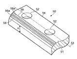
図2A、図2Cおよび図2Dは、ガイドレールと工作機械ベッドとの間に取り付けるための、各種の線形エンコーダスケール30,40,50の長さに沿った一部等角図である。エンコーダスケール30,40,50は、長いスケール部材31,41,51および、目盛36a,46a,48a,56a,58aを含む少なくとも1つのスケールトラック36,46,48,56,68を有する。スケール部材31,41,51は、概念上の長さ方向の中心線33,43,53を有する。図2Bは、図2Aに示される線形エンコーダスケール30の断面図である。
2A, 2C and 2D are partial isometric views along the length of various linear encoder scales 30, 40, 50 for mounting between guide rails and machine tool beds. The encoder scales 30, 40, 50 have
図2Aと図2Bに示されるエンコーダスケール30はスケール部材31を有し、これは略直平行六面体の計上で断面は略長方形である。スケール部材は、2対の対向する(反対側に位置する)面を有し、大きい方の対の対向面は図の上面31aと下面31bであり、小さい方の対の対向面は図の第一と第二の側面31d,31cである。上面31aと下面31bは、側面31d,31cと、スケール部材の長さ方向の縁部34,35,37,38で結合する。しかしながら、当然のことながら、エンコーダスケール30は、図2Aと図2Bに示されるものと異なる向きでも使用でき、その場合、本明細書における上面、下面および側面という言い方は当てはまらなくなる。
The
対向する上下面31a,31bは、スケール部材の長さと幅Wを画定し、対向する側面31c,31dは、スケール部材31の長さと厚さXを画定する。対向する上下面31a,31bは略平行であり、スケールの厚さXはスケール部材31の長さに沿って略均一である。スケール部材31の1つの長さ方向の縁部は基準縁部34として機能し、スケールトラック36の目盛36Aは、スケール部材31の中またはその上に直接、この基準縁部34に対して形成される。このように、目盛36aは、スケール部材31の一体部分である。基準縁部34が読取ヘッドとスケール30の間の相対移動軸に略平行となるようにスケール30が取り付けられると、目盛36aから得られる読取値の精度は、目盛36aが形成された精度とできるだけ近くなり、したがって、測定信号出力エラーは最小限となる。基準縁部34は、スケール部材31を、工作機械のベッドに形成された溝の縁部と整列させ、またこのようにして、スケール部材31を、工作機械ベッドの溝の縁部とも整列されたガイドレールの縁部と整列させるのに有益である。
The opposed upper and
スケールトラック36は、スケール部材31の上面31aに設置され、概念上の長さ方向の中心線33から基準縁部34と反対方向にずれている。スケールトラック36は基準縁部34と略平行に設置されて、目盛36aは基準縁部34に略垂直である。
The
スケール部材31にはボルト穴32が設けられ、これらはその長さ方向に沿って相互に離間され、スケール30を工作機械のベッドに固定するために、ボルトがこの穴を通過する。ボルト穴32は、ガイドレールのボルト穴の間の間隔に対応するように離間され、ガイドレールのボルト穴は工作機械ベッドのボルト穴に対応しており、それによって、スケール30をガイドレールと工作機械ベッドの間に固定することができる。スケール部材31のボルト穴32は、ガイドレールと工作機械ベッドのボルト穴より若干大きいため、スケール部材31のボルト穴32は正確に配置しなくてもよい。
The
図2Aに示されるエンコーダスケール30に関する一般的な説明は、図2Cと図2Dにそれぞれ示されるエンコーダスケール40と50に適用することができる。図2Aの参照番号31は、たとえば図2Cと図2Dのそれぞれ参照番号41と51に対応する。
The general description of
図2Cに示されるエンコーダスケール40には、スケール部材41の上に2つのスケールトラック46,48が設けられる。この実施形態において、スケールトラック46は概念上の長さ方向の中心線43から、スケール部材41の基準縁部44の反対方向にずらして設けられ、もう一方のスケールトラック48は、概念上の長さ方向の中心線43からスケール部材41の基準縁部44に近い方向にずらして設けられる。この場合、スケールトラック46,48は、使用時、ガイドレールの各側にそれぞれ取り付けられた2つの別のセンサによって読み取られてもよい。
The
図2Dに示されるエンコーダスケール50にもスケール部材41の上に2つのスケールトラック56,58が設けられる。この実施形態において、スケールトラック56,58は両方とも、概念上の長さ方向の中心線53から、スケール部材の基準縁部54と反対方向にずれている。この場合、2つのスケールトラック56,58は、同じセンサによって、または別のセンサによって読み取ることができる。
The
スケールトラックのペア46,48と56,58は、たとえば、1つの増分スケールと1つの基準マークスケール、または反対方向に延びる2つの絶対スケールとすることができる。 Scale track pairs 46, 48 and 56, 58 can be, for example, one incremental scale and one reference mark scale, or two absolute scales extending in opposite directions.
当然のことながら、基準縁部34の代わりに、基準面、たとえば第一の側面34を設けてもよい。
As a matter of course, a reference surface, for example, the
図3は、工作機械ベッド86に取り付けられたエンコーダスケール30とガイドアセンブリ70の断面図である。工作機械ベッド86には溝縁部86aが設けられ、それに当たるように、エンコーダスケール30の基準縁部34および/またはガイドレール72の第一の面72aを位置付けることができる。1列の離間されたボルト穴87が工作機械ベッド86に設けられ、この列は、溝縁部86aに略平行に延びる。
FIG. 3 is a cross-sectional view of the
ガイドアセンブリ70は、長いガイドレール72と、ガイドレール72上に取り付けられ、ローラまたはボール要素76の上でガイドレール72の長さに沿って移動可能なガイドキャリッジ74を含む。ガイドレール72は、ガイドレール72の長さと幅W1を画定する取付面78と、取付面78に略垂直で、ガイドレール72の長さに沿って延びる第一の面72aを有する。ガイドレール72には複数のボルト穴90が設けられ、ボルト穴はガイドレールの長さに沿って、工作機械ベッド86のボルト穴87の距離に対応する距離だけ離間されている。
The
エンコーダスケール30は、図2Aと図2Bに関して説明したように、スケール部材の長さと幅W2を画定する略平行な上面と下面31a,31bと、上面31aに設けられた目盛を有するスケールトラック36と、スケール部材31の長さと厚さXを画定する側面31c,31dとを有する。スケール部材31の1つの長さ方向の縁部は、基準縁部34として機能する。複数のボルト穴32がスケール部材31を貫通して設けられ、これらはその長さに沿って離間され、スケール部材31のボルト穴32は、ガイドケール72のボルト穴90と工作機械ベッド86のボルト穴87に対応するように離間されている。
As described with reference to FIGS. 2A and 2B, the
取付時に、エンコーダスケール30とガイドレール72は、工作機械ベッド86に取り付けられる。まず、スケール部材31の基準縁部34は、工作機械ベッド86の溝縁部86aに当たるように位置付けられ、エンコーダスケール30のボルト穴32は、工作機械ベッド86のボルト穴87と位置合わせされる。この位置において、スケール部材31の下面31bは、エンコーダスケール30の全長に沿って、工作機械のベッド86と接触する。スケール部材31の上面と下面31a,31bは平行で、それゆえ、エンコーダスケール30の長さに沿って均一な距離Xだけ離れているため、スケール部材31の上面31aの位置は、工作機械ベッド86の位置に対して既知である。
At the time of attachment, the
ガイドレール72は次に、エンコーダ30の上面31aに配置され、ガイドレールの第一の縁部72aは工作機械ベッド86の溝縁部86aに当たるように位置付けられる。ガイドレール72の幅W1は、スケール部材31の幅W2より小さく、それによって、ガイドレール72はエンコーダスケール30の第一の部分30aをガイドレール72と工作機械のベッド86の間に挟む。スケールトラック36が設けられ、エンコーダスケール30の第二の部分30bは、ガイドレール72の下から突出し、ガイドキャリッジ74に取り付けられた読取ヘッド84が目盛36aにアクセスして、これを感知できる。エンコーダスケール30とガイドレール72を工作機械ベッド86に固定するために、ボルト88がボルト穴90,32を通って、対応して離間されたベッド86の穴87に挿入される。エンコーダスケール30は、それがガイドレール72と工作機械ベッド86の間に位置付けられたときに、スケール部材がガイドレールの下から突出するように製造される。
The
当然のことであるが、使用されるエンコーダスケールがリール状で保管されている場合、スケールを伸ばし、工作機械ベッドの上に載せてから、その上にガイドレールを固定してもよい。ガイドレールをスケールの一部の上に位置付けることによって、ガイドレールの重量が、スケールをその長さに沿って平らにするのに役立ち、ガイドレールを工作機械にボルトで固定することで、それら2つの間に保持されるスケールが、ガイドレールの平坦化効果を高めることができる。 As a matter of course, when the encoder scale used is stored in a reel shape, the scale may be stretched and placed on the machine tool bed, and then the guide rail may be fixed thereon. By positioning the guide rail over a part of the scale, the weight of the guide rail helps to flatten the scale along its length, and they can be secured by bolting the guide rail to the machine tool. The scale held between the two can enhance the flattening effect of the guide rail.
ガイドアセンブリ70の寸法はわかっており、スケール部材31の厚さXが均一であることから、ガイドアセンブリ70の位置を、それゆえ、工作機械のベッド86に対して決定することができる。工作機械のベッドは概して平らであり、スケール部材31の厚さが一定であるため、目盛36aが形成されるスケール部材31の表面もまた平らであるはずである。ガイドレール72とガイドキャリッジ74の寸法がわかっていて、ガイドレール72の長さに沿って一定であるため、ガイドキャリッジ74に支持される読取ヘッド84は、工作機械ベッド86から一定の既知の距離と、目盛が形成されるスケール部材31の表面から一定の既知の距離の地点とに設置される。読取ヘッド84をスケールトラック36の長さに沿って、目盛36aから一定の距離に設置することによって、スケール36と読取ヘッド84の間の変位の正確な測定値を得ることができる。
Since the dimensions of the
エンコーダスケール30の(スケールトラック36の)目盛を感知するセンサ(図示せず)を含む読み取りヘッド84は、ガイドキャリッジ74に取り付けられる。読取ヘッド84の目盛82に対する高さを設定するために、スペーサ(図示せず)を目盛と読取ヘッド84の間に設置し、その一方で読取ヘッド84をガイドキャリッジ74に固定する。使用時、ガイドキャリッジ74は、ガイドレール72の長さに沿ってガイドレール72に対して移動され、それによって読取ヘッド84はエンコーダスケール80の上の目盛82に対して移動される。
A read
図4Aは、ガイドレールをエンコーダスケール90に対して位置付けるための、立ち上がった縁部100を有するエンコーダスケール90の等角図である。図4Bは、工作機械ベッド104に取り付けられた図4Aのエンコーダスケール90とガイドレール102の断面図である。エンコーダスケール90は、図中、それぞれ上面と下面91a,91bとして示される2つの大きな平行面を有する長いスケール部材91と、スケール部材91を貫通するボルト穴92であって、スケール部材91の概念上の中心線93に沿って配置されるボルト穴92と、立ち上がった縁部100と、スケールマーキング96aを有するスケールトラック96を含む。スケールトラック96はスケール部材91の上面91aに設置され、ボルト穴92の第一の側にずれ、立ち上がった縁部100はボルト穴の、スケールトラック95と反対側に設置される。
FIG. 4A is an isometric view of the
立ち上がった縁部100は、図4Bのように使用時にガイドレール102を位置づける際に当てる縁部となる。このようにガイドレール102の位置は、x方向には工作機械ベッド104とスケールトラック96に対して、またy方向にはスケールトラック96に対して、正確にわかる。y方向にスケールトラック96に対するガイドレール102の位置がわかることは、(ガイドレールに支持されるガイドキャリッジの上に支持される)読取ヘッドの位置をy方向において目盛に対して固定できる点で有利である。読取ヘッドがスケールからy方向にふらつかない(ヨーイングと呼ばれる)ようにすることによって、読取ヘッドとスケールの相対的な位置をより正確に測定することができる。
As shown in FIG. 4B, the raised
立ち上がった縁部のないスケール部材を使用した場合、ガイドレールとスケール部材の相対的位置は、図3に示されるように、ガイドレールとスケール部材の両方を工作機械のベッドの溝縁部に当接させることによって固定できる。 When a scale member without a raised edge is used, the relative position of the guide rail and the scale member is such that both the guide rail and the scale member are in contact with the groove edge of the machine tool bed as shown in FIG. Can be fixed by touching.
図5は、これ以前の図に示されているようなボルト穴またはその他の取付穴の代わりに、取付スロット112を有するエンコーダスケール110の等角図である。スケールトラック106はスケール部材111の第一の縁部111cに向かって設けられ、取付スロット112はスケール部材111の第二の縁部111dから延びる。取付スロット112によって、ガイドレールアセンブリの下で、エンコーダスケールを工作機械ベッドにより容易に組み込むことができる。ガイドレールアセンブリがすでに工作機械ベッドに取り付けられている場合、ガイドレールを工作機械のベッドに固定するボルトを緩めてもよく、ガイドレールを持ち上げて、エンコーダスケール110をガイドレールの下にスライドさせ、取付スロット112をボルトの周辺に嵌める。その後、ボルトを締めて、エンコーダスケールを工作機械のベッドとガイドレールの間の所定の位置に固定してもよい。
FIG. 5 is an isometric view of
図2から図5の各々に示されるスケールトラックは、スケール部材にエッチングによって形成されるパッシブ(消極)磁気スケールトラックである。スケール部材にエッチングすることは、たとえば、レーザエッチング、化学エッチング、機械エッチングまたはそれらの組み合わせであってもよい。エッチングの代わりに、目盛は、たとえばスケール部材に材料を追加して水平部と溝を形成することによって形成してもよい。当然のことながら、パッシブ磁気スケールトラックの代わりに、その他どのようなタイプのスケールトラックでも使用でき、たとえば、アクティブ磁気、光学、容量または誘導スケールトラックがある。このようなスケールトラックの目盛は、周知の方法で形成してもよい。これに加えて、当然のことながら、目盛はトラック以外の配置でスケール部材に形成してもよい。使用時に目盛を感知するための適当なセンサをアセンブリのガイドキャリッジに設置することができる。 The scale track shown in each of FIGS. 2 to 5 is a passive (depolarized) magnetic scale track formed on the scale member by etching. Etching the scale member may be, for example, laser etching, chemical etching, mechanical etching, or a combination thereof. Instead of etching, the scale may be formed by, for example, adding a material to the scale member to form a horizontal portion and a groove. Of course, any other type of scale track could be used instead of a passive magnetic scale track, for example an active magnetic, optical, capacitive or inductive scale track. Such scale track scales may be formed by a known method. In addition to this, as a matter of course, the scale may be formed on the scale member in an arrangement other than the track. Appropriate sensors for sensing the scale in use can be placed on the guide carriage of the assembly.
パッシブ磁気スケールトラックは堅牢であるため、工作機械環境において有利となりえ、スケール表面にたとえば埃や冷媒が付着しても、依然として測定を行うことができる。これに加えて、磁気スケールの表面に、たとえば機械の削りくずによって傷がついたとしても、依然として正確な測定値が得られる。リップシール等のシールを読取ヘッドの上に設置して、読取ヘッドがスケールの上を通過する際にスケールから屑を拭き取ることにより、屑が入り込むことなく、読取ヘッドのセンサがスケールを感知できる。特許文献3に記載されているように、「湿式読取ヘッド」を設置してもよく、この場合、読取ヘッドには、窓と、読取ヘッドの移動方向に向かって窓の前方にワイパ要素を設置してもよい。 Passive magnetic scale tracks are robust and can be advantageous in machine tool environments and can still be measured even if, for example, dust or coolant adheres to the scale surface. In addition to this, even if the surface of the magnetic scale is damaged, for example by mechanical shavings, an accurate measurement is still obtained. By installing a seal such as a lip seal on the read head and wiping off debris from the scale as the read head passes over the scale, the sensor of the read head can sense the scale without entering the debris. As described in Patent Document 3, a “wet read head” may be installed. In this case, the read head is provided with a window and a wiper element in front of the window in the moving direction of the read head. May be.
図6は、パッシブ磁気スケール120の長さに沿った輪郭図と、スケールを感知するためのセンサ130の断面図であり、スケールは、長さに沿って交互に配置された溝124と水平部122によって形成される増分目盛を有する。パッシブ磁気スケール120は、フェライト系ステンレススチール鋼から作製される。スケールはあるいは、どのような磁性材料から作製してもよく、たとえば、カーボンスチールまたは純鉄、あるいは磁性材料の混合物等であってもよい。
FIG. 6 is a profile view along the length of the passive
パッシブ磁気スケール120を感知するセンサ130は、永久磁石132とホール素子134を備える。センサ130が使用時にスケール120の上に位置付けられると、磁界密度はホール素子134によって測定され、センサ130がスケール120の長さに沿って矢印Aの方向に移動されると、測定された磁界密度は、エンコーダスケール部材の長さに沿って変化する。測定された磁界密度がこのように変化する主な理由は、永久磁石とスケールの磁性材料の間の距離のばらつきである。この効果の二次的な理由は、センサの付近に設けられた磁性材料の量である。ホール素子が水平部122の上を通過する際に感知される磁界密度は高くなり、ホール素子が溝124の上を通過する際に感知される磁界密度は低くなる。
The
水平部122の上の位置から溝124の上の位置まで測定される磁界密度の変化を最大限にするために、センサ130は、スケールにできるだけ近い位置に正確に位置付けなければならない。
In order to maximize the change in magnetic field density measured from a position above the
当然のこととして、巨大磁気抵抗センサ(GMR)または異方性磁気抵抗センサ(AMR)または複数のホール素子を、上記のホール素子134の代わりに用いてもよい。
Of course, a giant magnetoresistive sensor (GMR) or anisotropic magnetoresistive sensor (AMR) or a plurality of Hall elements may be used in place of the
図7は、軸受142と機械146の取付面144との間に取り付けられた回転エンコーダスケール部材140の断面図である。軸受142は、静止軌道面142aと可動軌道面142bと転がり軸受142cとを備える。機械は、静止アセンブリ150と、第一の構成部品148aおよび第二の構成部品148bを有して軸Yの周りに回転可能な回転アセンブリ148を備える。読取ヘッド152は、回転エンコーダスケール部材140に設置された目盛141を読み取るために設置される。
FIG. 7 is a cross-sectional view of the rotary
静止アセンブリ150は、読取ヘッド152と軸受アセンブリ142の静止軌道面142aとを支持する。可動軌道面142bには、ボルト154によって機械146の回転可能アセンブリ148が連結される。エンコーダスケール部材140は、軸受142の可動軌道面142bと回転可能なアセンブリ148の取付面144の間に位置付けられ、ボルト154を締めると、回転可能なアセンブリ148の第一の構成要素148aが第二の構成要素148bに向かって矢印Bの方向に引かれ、エンコーダスケール部材140を軸受142の可動軌道面142bと回転アセンブリ148の取付面144との間に留め付ける(把持する、クランプする)ようになっている。この実施形態において、軸受142の可動軌道面142bとエンコーダスケール部材140の間にシム156が設けられ、それによってエンコーダスケール部材140は、軸受142の静止軌道面142aから離間される。
The
目盛141は、エンコーダスケール部材140の上に設置され、それによって読取ヘッド152によって感知可能である。回転アセンブリ148と目盛141が読取ヘッド152に対して移動するとき、読取ヘッド152が目盛141を読み取ることにより、回転アセンブリ148の回転が測定される。
The
機械146は、回転アセンブリ148に取り付けられた物体を、静止アセンブリ150に対して正確に位置決めするための座標位置決め装置であってもよい。前記物体は、回転アセンブリ148の外面149に取り付けてもよい。
当業者にとっては当然のことであるが、上記の実施形態はすべて、いずれの向きで設置してもよい。また、当然のことながら、スケール部材は、装置の可動部材と静止部材のいずれにも取り付けることができ、センサを可動部材または静止部材のうちのもう一方に取り付けて、スケールとセンサが相対的に移動可能であるようにしてもよい。 As will be appreciated by those skilled in the art, all of the above embodiments may be installed in any orientation. Of course, the scale member can be attached to either the movable member or the stationary member of the apparatus, and the sensor is attached to the other of the movable member or the stationary member so that the scale and the sensor are relatively It may be movable.
Claims (42)
前記取付面に取付可能な移動案内部材と、
目盛を感知するセンサを備える第一の部材であって、前記移動案内部材に取り付け可能な第一の部材と、
使用時に前記センサによって感知可能な第一の目盛セットを含むエンコーダスケール部材と、
を備える座標位置決め装置であって、
前記移動案内部材と前記エンコーダスケール部材が、取付固定具により、前記取付面に同時に取り付けられ、
前記移動案内部材と前記エンコーダスケール部材が取り付けられたとき、前記エンコーダスケール部材が前記取付面によって少なくとも前記第一の目盛セットの付近で支持されるよう、前記エンコーダスケール部材の少なくとも前記第一の目盛セットに隣接する部分が、前記取付面と前記移動案内部材の間に挟まれることによって保持されることを特徴とする座標位置決め装置。 A mounting surface;
A movement guide member attachable to the attachment surface;
A first member including a sensor for detecting a scale, the first member attachable to the movement guide member;
An encoder scale member that includes a first scale set that can be sensed by the sensor in use;
A coordinate positioning device comprising:
The movement guide member and the encoder scale member are simultaneously attached to the attachment surface by an attachment fixture,
When the moving guide member and the encoder scale member is mounted, said as the encoder scale member is supported in the vicinity of at least the first scale set by said mounting surface, at least the first scale of the encoder scale member A coordinate positioning apparatus, wherein a portion adjacent to the set is held by being sandwiched between the mounting surface and the movement guide member.
使用時に、前記センサによって感知可能な第一の目盛セットと、 A first scale set that can be sensed by the sensor in use;
前記移動案内部材と前記エンコーダスケール部材が取付固定具により前記取付面に同時に取り付けられたとき、前記エンコーダスケール部材が前記取付面によって少なくとも前記第一目盛セットの付近で支持されるよう、前記エンコーダスケール部材の少なくとも前記第一の目盛セットに隣接する部分が前記取付面と前記移動案内部材の間に挟まれることによって固定されることを許容する少なくとも1つの取付機能部と、 When the movement guide member and the encoder scale member are simultaneously attached to the attachment surface by an attachment fixture, the encoder scale is supported by the attachment surface at least in the vicinity of the first scale set. At least one attachment function portion that allows at least a portion of the member adjacent to the first scale set to be fixed by being sandwiched between the attachment surface and the movement guide member;
を備えることを特徴とするエンコーダスケール部材。An encoder scale member comprising:
(i)前記取付面、前記移動案内部材および前記エンコーダスケール部材を準備するステップと、 (I) preparing the mounting surface, the movement guide member, and the encoder scale member;
(ii)前記エンコーダスケール部材が前記取付面によって少なくとも前記第一の目盛セットの付近で支持されるよう、前記エンコーダスケール部材の少なくとも前記第一の目盛セットに隣接する部分を、前記取付面と前記移動案内部材の間に挟んで位置付けるステップと、 (Ii) at least a portion of the encoder scale member adjacent to the first scale set so that the encoder scale member is supported by the mounting surface at least in the vicinity of the first scale set. A step of positioning between the movement guide members;
(iii)前記移動案内部材と前記エンコーダスケール部材を前記座標位置決め装置の前記取付面に同時に固定するステップと、 (Iii) simultaneously fixing the movement guide member and the encoder scale member to the mounting surface of the coordinate positioning device;
を含むことを特徴とする方法。A method comprising the steps of:
(i)前記エンコーダスケール部材が前記取付面によって少なくとも前記第一の目盛セットの付近で支持されるよう、前記エンコーダスケール部材を前記座標位置決め装置の前記取付面に位置付けるステップと、 (I) positioning the encoder scale member on the mounting surface of the coordinate positioning device so that the encoder scale member is supported by the mounting surface at least in the vicinity of the first scale set;
(ii)前記エンコーダスケール部材の少なくとも前記第一の目盛セットに隣接する部分が前記移動案内部材と前記座標位置決め装置の前記取付面との間に存在するよう、前記移動案内部材を前記エンコーダスケール部材に位置付けるステップと、 (Ii) The encoder scale member is moved so that at least a portion of the encoder scale member adjacent to the first scale set exists between the movement guide member and the mounting surface of the coordinate positioning device. A step positioned at
をさらに含むことを特徴とする、請求項28に記載の方法。The method of claim 28, further comprising:
(i)前記移動案内部材を前記座標位置決め装置の前記取付面から少なくとも部分的に取り外すステップと、 (I) at least partially removing the movement guide member from the mounting surface of the coordinate positioning device;
(ii)前記移動案内部材を前記座標位置決め装置の前記取付面から少なくとも部分的に分離させるステップと、 (Ii) separating the movement guide member at least partially from the mounting surface of the coordinate positioning device;
をさらに含むことを特徴とする、請求項32に記載の方法。The method of claim 32, further comprising:
前記取付面に取付可能な移動案内部材と、 A movement guide member attachable to the attachment surface;
目盛を感知するためのセンサを支持する第一の部材であって、前記移動案内部材に取付可能な第一の部材と、 A first member for supporting a sensor for detecting a scale, the first member attachable to the movement guide member;
目盛を有するエンコーダスケール部材と、 An encoder scale member having a scale,
を備え、With
前記移動案内部材と前記エンコーダスケール部材が、取付固定具により、前記取付面に同時に取り付けられ、 The movement guide member and the encoder scale member are simultaneously attached to the attachment surface by an attachment fixture,
前記移動案内部材と前記エンコーダスケール部材が取り付けられたとき、前記エンコーダスケール部材の少なくとも前記目盛に隣接する部分は、前記取付面と前記移動案内部材の間に挟まれることによって保持され、前記エンコーダスケール部材の少なくとも前記目盛の付近の部分が前記取付面によって支持されることを特徴とする、座標位置決め装置。 When the movement guide member and the encoder scale member are attached, at least a portion of the encoder scale member adjacent to the scale is held by being sandwiched between the attachment surface and the movement guide member, and the encoder scale A coordinate positioning apparatus, wherein at least a portion of the member in the vicinity of the scale is supported by the mounting surface.
Applications Claiming Priority (3)
| Application Number | Priority Date | Filing Date | Title |
|---|---|---|---|
| GB0902547.9 | 2009-02-16 | ||
| GBGB0902547.9A GB0902547D0 (en) | 2009-02-16 | 2009-02-16 | Encoder scale member and method for mounting |
| PCT/GB2010/000267 WO2010092359A1 (en) | 2009-02-16 | 2010-02-16 | Encoder scale member and method for mounting |
Publications (3)
| Publication Number | Publication Date |
|---|---|
| JP2012518167A JP2012518167A (en) | 2012-08-09 |
| JP2012518167A5 JP2012518167A5 (en) | 2013-04-04 |
| JP5596056B2 true JP5596056B2 (en) | 2014-09-24 |
Family
ID=40548256
Family Applications (1)
| Application Number | Title | Priority Date | Filing Date |
|---|---|---|---|
| JP2011549657A Expired - Fee Related JP5596056B2 (en) | 2009-02-16 | 2010-02-16 | Encoder scale member and mounting method |
Country Status (6)
| Country | Link |
|---|---|
| US (1) | US8739425B2 (en) |
| EP (1) | EP2396142B1 (en) |
| JP (1) | JP5596056B2 (en) |
| CN (1) | CN102317034B (en) |
| GB (1) | GB0902547D0 (en) |
| WO (1) | WO2010092359A1 (en) |
Cited By (1)
| Publication number | Priority date | Publication date | Assignee | Title |
|---|---|---|---|---|
| KR20210095210A (en) * | 2018-12-26 | 2021-07-30 | 티에치케이 가부시끼가이샤 | Sensor installation structure of rolling guide device |
Families Citing this family (6)
| Publication number | Priority date | Publication date | Assignee | Title |
|---|---|---|---|---|
| GB0902547D0 (en) * | 2009-02-16 | 2009-04-01 | Renishaw Plc | Encoder scale member and method for mounting |
| DE102010054102A1 (en) * | 2010-12-10 | 2012-06-14 | Robert Bosch Gmbh | Linear movement device, has measuring element provided with multiple measuring markings and arranged parallel to attachment surface beside guide rail under U-shaped leg part of carriage, and scanning device arranged in region of leg part |
| US9095915B2 (en) * | 2012-11-15 | 2015-08-04 | Seagate Technology Llc | Axially positioning a rotating article |
| JP6085658B1 (en) * | 2015-10-28 | 2017-02-22 | Thk株式会社 | Position detecting device and motion guide device with position detecting device |
| US20240017365A1 (en) * | 2020-12-10 | 2024-01-18 | Dmg Mori Co., Ltd. | Feed apparatus |
| CN114812621A (en) * | 2022-05-17 | 2022-07-29 | 上海麦可洛自动化科技有限公司 | Linear encoder positioning structure and positioning method for splicing tracks |
Family Cites Families (32)
| Publication number | Priority date | Publication date | Assignee | Title |
|---|---|---|---|---|
| US4137643A (en) * | 1977-08-01 | 1979-02-06 | American Standard Inc. | Gauging assembly |
| IT1150217B (en) * | 1982-03-02 | 1986-12-10 | Microingranaggi Bianchini Srl | PROCEDURE FOR DETECTING DIMENSIONS AND PERFORMING LINEAR MEASUREMENTS |
| CH686322A5 (en) * | 1990-04-25 | 1996-02-29 | Schneeberger Ag Maschf | Guiding device with measuring device. |
| JPH0581624U (en) * | 1992-04-13 | 1993-11-05 | 三菱重工業株式会社 | Line motion detector |
| JPH07213045A (en) | 1994-01-20 | 1995-08-11 | Hitachi Metals Ltd | Linear rail integrated linear scale |
| DE4438079A1 (en) | 1994-10-25 | 1996-05-02 | Heidenhain Gmbh Dr Johannes | guide |
| DE19526517C2 (en) | 1995-07-20 | 2000-08-24 | Zeiss Carl Jena Gmbh | Arrangement for attaching a length measuring device |
| DE19912310B4 (en) | 1999-03-19 | 2007-11-29 | Dr. Johannes Heidenhain Gmbh | A position |
| JP3305288B2 (en) | 1999-09-20 | 2002-07-22 | 折尾精密株式会社 | Machine tool precision measuring device |
| US6772531B1 (en) * | 1999-11-30 | 2004-08-10 | Renishaw Plc | Measurement apparatus including a track for a measurement scale and apparatus for tensioning the scale |
| GB0023289D0 (en) | 2000-09-22 | 2000-11-08 | Renishaw Plc | Determination of displacement |
| US6820348B2 (en) * | 2001-02-09 | 2004-11-23 | Acu-Rite, Inc. | Mounting tool for linear encoders |
| DE10254358B4 (en) * | 2001-12-17 | 2005-04-14 | Dr. Johannes Heidenhain Gmbh | Carrier body for a position measuring device |
| JP4509483B2 (en) | 2002-03-30 | 2010-07-21 | ドクトル・ヨハネス・ハイデンハイン・ゲゼルシヤフト・ミツト・ベシユレンクテル・ハフツング | Linear encoder and linear guide unit |
| GB0216487D0 (en) * | 2002-07-16 | 2002-08-21 | Renishaw Plc | A rotary scale |
| GB0216488D0 (en) * | 2002-07-16 | 2002-08-21 | Renishaw Plc | Scale reading apparatus |
| JP3991000B2 (en) * | 2003-03-25 | 2007-10-17 | 住友重機械工業株式会社 | Linear scale mounting method and apparatus |
| DE10339895A1 (en) | 2003-08-29 | 2005-05-19 | Siemens Ag | Optical distance non-contact measuring assembly for e.g. production machinery, plant and machinery, drive systems, mechanical handling |
| DE10347360B4 (en) * | 2003-10-11 | 2021-07-01 | Robert Bosch Gmbh | Guide with measuring device and method for producing such a guide |
| US7105956B2 (en) | 2004-04-23 | 2006-09-12 | Aerotech, Inc. | High precision z-theta stage |
| JP2006027146A (en) | 2004-07-16 | 2006-02-02 | Ricoh Co Ltd | Inkjet printer |
| DE102005021345A1 (en) * | 2005-05-04 | 2006-11-09 | Schaeffler Kg | Linear guide unit with length measuring system |
| JP2006322811A (en) | 2005-05-19 | 2006-11-30 | Uchiyama Mfg Corp | Magnetic encoder and member to be detected |
| EP1742023A1 (en) | 2005-07-06 | 2007-01-10 | Schneeberger Holding AG | Linear motion guide with apparatus for measuring the position |
| EP1752851A1 (en) * | 2005-08-12 | 2007-02-14 | Schneeberger Holding AG | Linear guiding system with measuring means |
| DE102006003980A1 (en) * | 2006-01-27 | 2007-08-02 | Schaeffler Kg | Linear guide with length measurement system, used in e.g. metal- or wood-working machinery, contains magnetic components forming scale, inside concentric tubes |
| JP2008089027A (en) * | 2006-09-29 | 2008-04-17 | Nsk Ltd | Linear guide apparatus and end cap |
| DE102007009461A1 (en) * | 2007-01-25 | 2008-07-31 | Schaeffler Kg | Guide rail of a linear guide |
| JP4922033B2 (en) * | 2007-03-26 | 2012-04-25 | タツモ株式会社 | Position detection device |
| DE102007042796A1 (en) * | 2007-09-07 | 2009-03-12 | Robert Bosch Gmbh | Guide rail with absolute measuring standard |
| US20100162582A1 (en) * | 2008-12-30 | 2010-07-01 | Chih-Mao Shiao | Positioning Device of a Magnetic Ruler |
| GB0902547D0 (en) * | 2009-02-16 | 2009-04-01 | Renishaw Plc | Encoder scale member and method for mounting |
-
2009
- 2009-02-16 GB GBGB0902547.9A patent/GB0902547D0/en not_active Ceased
-
2010
- 2010-02-16 JP JP2011549657A patent/JP5596056B2/en not_active Expired - Fee Related
- 2010-02-16 CN CN201080007881.XA patent/CN102317034B/en not_active Expired - Fee Related
- 2010-02-16 EP EP10707630.9A patent/EP2396142B1/en not_active Not-in-force
- 2010-02-16 US US13/145,143 patent/US8739425B2/en active Active
- 2010-02-16 WO PCT/GB2010/000267 patent/WO2010092359A1/en active Application Filing
Cited By (2)
| Publication number | Priority date | Publication date | Assignee | Title |
|---|---|---|---|---|
| KR20210095210A (en) * | 2018-12-26 | 2021-07-30 | 티에치케이 가부시끼가이샤 | Sensor installation structure of rolling guide device |
| KR102341986B1 (en) * | 2018-12-26 | 2021-12-22 | 티에치케이 가부시끼가이샤 | Sensor installation structure of rolling guide device |
Also Published As
| Publication number | Publication date |
|---|---|
| GB0902547D0 (en) | 2009-04-01 |
| US20110271540A1 (en) | 2011-11-10 |
| EP2396142A1 (en) | 2011-12-21 |
| EP2396142B1 (en) | 2018-11-14 |
| US8739425B2 (en) | 2014-06-03 |
| CN102317034B (en) | 2014-07-30 |
| WO2010092359A1 (en) | 2010-08-19 |
| CN102317034A (en) | 2012-01-11 |
| JP2012518167A (en) | 2012-08-09 |
Similar Documents
| Publication | Publication Date | Title |
|---|---|---|
| JP5596056B2 (en) | Encoder scale member and mounting method | |
| EP2053362B1 (en) | Position sensor and bias magnetic field generating device | |
| JP5386081B2 (en) | Scale and read head device | |
| CN101836086B (en) | Magnetic encoder and reference mark applicator | |
| US8040099B2 (en) | Position device in gantry type of construction | |
| US20090151182A1 (en) | Measuring device | |
| US8141265B2 (en) | Scale track | |
| US11519763B2 (en) | Assembly including a main support, an intermediate support disposed on the main support, and a scale disposed on the intermediate support | |
| JP2007192722A (en) | Position detector | |
| US9835430B2 (en) | Position-measuring device | |
| US7743527B2 (en) | Position detector | |
| JP4783698B2 (en) | Electromagnetic induction encoder | |
| GB2463270A (en) | Scale alignment tool | |
| JP7402108B2 (en) | position measuring device | |
| US11940304B2 (en) | Position-measuring device having four scanning units and two measuring graduations | |
| JPH0662304U (en) | Magnetic linear scale | |
| JP2016042062A (en) | Displacement detection device | |
| TWI388800B (en) | Magnetic position sensor by using digital and analogical sensing readers |
Legal Events
| Date | Code | Title | Description |
|---|---|---|---|
| A521 | Request for written amendment filed |
Free format text: JAPANESE INTERMEDIATE CODE: A523 Effective date: 20130212 |
|
| A621 | Written request for application examination |
Free format text: JAPANESE INTERMEDIATE CODE: A621 Effective date: 20130212 |
|
| A977 | Report on retrieval |
Free format text: JAPANESE INTERMEDIATE CODE: A971007 Effective date: 20130626 |
|
| A131 | Notification of reasons for refusal |
Free format text: JAPANESE INTERMEDIATE CODE: A131 Effective date: 20130903 |
|
| A601 | Written request for extension of time |
Free format text: JAPANESE INTERMEDIATE CODE: A601 Effective date: 20131203 |
|
| A602 | Written permission of extension of time |
Free format text: JAPANESE INTERMEDIATE CODE: A602 Effective date: 20131210 |
|
| A521 | Request for written amendment filed |
Free format text: JAPANESE INTERMEDIATE CODE: A523 Effective date: 20140303 |
|
| TRDD | Decision of grant or rejection written | ||
| A01 | Written decision to grant a patent or to grant a registration (utility model) |
Free format text: JAPANESE INTERMEDIATE CODE: A01 Effective date: 20140708 |
|
| A61 | First payment of annual fees (during grant procedure) |
Free format text: JAPANESE INTERMEDIATE CODE: A61 Effective date: 20140806 |
|
| R150 | Certificate of patent or registration of utility model |
Ref document number: 5596056 Country of ref document: JP Free format text: JAPANESE INTERMEDIATE CODE: R150 |
|
| R250 | Receipt of annual fees |
Free format text: JAPANESE INTERMEDIATE CODE: R250 |
|
| R250 | Receipt of annual fees |
Free format text: JAPANESE INTERMEDIATE CODE: R250 |
|
| R250 | Receipt of annual fees |
Free format text: JAPANESE INTERMEDIATE CODE: R250 |
|
| R250 | Receipt of annual fees |
Free format text: JAPANESE INTERMEDIATE CODE: R250 |
|
| LAPS | Cancellation because of no payment of annual fees |