JP5593777B2 - projector - Google Patents
projector Download PDFInfo
- Publication number
- JP5593777B2 JP5593777B2 JP2010077516A JP2010077516A JP5593777B2 JP 5593777 B2 JP5593777 B2 JP 5593777B2 JP 2010077516 A JP2010077516 A JP 2010077516A JP 2010077516 A JP2010077516 A JP 2010077516A JP 5593777 B2 JP5593777 B2 JP 5593777B2
- Authority
- JP
- Japan
- Prior art keywords
- cooling
- duct
- cooling air
- outlet
- light
- Prior art date
- Legal status (The legal status is an assumption and is not a legal conclusion. Google has not performed a legal analysis and makes no representation as to the accuracy of the status listed.)
- Expired - Fee Related
Links
Images


Classifications
-
- G—PHYSICS
- G03—PHOTOGRAPHY; CINEMATOGRAPHY; ANALOGOUS TECHNIQUES USING WAVES OTHER THAN OPTICAL WAVES; ELECTROGRAPHY; HOLOGRAPHY
- G03B—APPARATUS OR ARRANGEMENTS FOR TAKING PHOTOGRAPHS OR FOR PROJECTING OR VIEWING THEM; APPARATUS OR ARRANGEMENTS EMPLOYING ANALOGOUS TECHNIQUES USING WAVES OTHER THAN OPTICAL WAVES; ACCESSORIES THEREFOR
- G03B21/00—Projectors or projection-type viewers; Accessories therefor
- G03B21/14—Details
- G03B21/16—Cooling; Preventing overheating
Landscapes
- Physics & Mathematics (AREA)
- General Physics & Mathematics (AREA)
- Projection Apparatus (AREA)
- Liquid Crystal (AREA)
Description
本発明は、プロジェクターに関する。 The present invention relates to a projector.
従来、外部から冷却空気を吸入して吐出する冷却ファンと、当該冷却ファンに接続されて冷却対象である光変調装置に冷却空気を流出するダクトとを備えるプロジェクターが知られている(例えば、特許文献1参照)。 2. Description of the Related Art Conventionally, a projector is known that includes a cooling fan that sucks and discharges cooling air from the outside, and a duct that is connected to the cooling fan and flows out of cooling air to a light modulation device that is a cooling target (for example, a patent). Reference 1).
特許文献1において、ダクトの一端側が冷却ファンに接続され、他端側が光変調装置の配設位置近傍まで延出し、冷却ファンから吐出された冷却空気が光変調装置まで導かれるようになっている。そして、冷却空気は、ダクトの他端側に形成された流出口から光変調装置に対して、下方から上方に向けて流出し、光変調装置が冷却される。具体的には、冷却ファンから吐出された冷却空気は、ダクト内において、光変調装置への入射光束の光軸と直交する方向に流れた後、ダクトの他端の壁面に衝突して、この壁面により流路方向が変えられ、流出口から流出する。 In Patent Document 1, one end side of a duct is connected to a cooling fan, the other end side extends to the vicinity of the position where the light modulation device is disposed, and cooling air discharged from the cooling fan is guided to the light modulation device. . Then, the cooling air flows out from the lower side toward the upper side with respect to the light modulation device from the outlet formed on the other end side of the duct, and the light modulation device is cooled. Specifically, the cooling air discharged from the cooling fan flows in a direction perpendicular to the optical axis of the incident light beam to the light modulation device in the duct, and then collides with the wall surface at the other end of the duct. The flow path direction is changed by the wall surface and flows out from the outlet.
しかしながら、特許文献1によれば、冷却空気は、ダクトの他端の壁面に衝突することで、壁面で摩擦が発生するため、圧力損失により冷却空気の流速が低下する。そして、冷却空気の流速が低下することに伴って、流出口から流出する冷却空気の流量も減少し、冷却対象に対して十分な流量の冷却空気を流出できず、冷却対象を良好に冷却できないという問題がある。 However, according to Patent Document 1, since the cooling air collides with the wall surface at the other end of the duct, friction is generated on the wall surface, so that the flow velocity of the cooling air decreases due to pressure loss. As the flow rate of the cooling air decreases, the flow rate of the cooling air flowing out from the outlet also decreases, and the cooling air with a sufficient flow rate cannot be flown out of the cooling target, and the cooling target cannot be cooled well. There is a problem.
本発明の目的は、冷却対象の冷却効率を向上できるプロジェクターを提供することにある。 An object of the present invention is to provide a projector that can improve the cooling efficiency of a cooling target.
本発明のプロジェクターは、冷却対象に対して冷却空気を送風する冷却装置を備えたプロジェクターであって、前記冷却装置は、冷却空気を吐出する複数の冷却ファンと、一端側が前記複数の冷却ファンに接続され、前記冷却空気を異なる方向から前記冷却対象に導く複数のダクトとを備え、前記複数のダクトは、他端側において、連通するとともに、前記各冷却空気が流出する流出口を備えていることを特徴とする。 The projector of the present invention is a projector including a cooling device that blows cooling air to an object to be cooled. The cooling device includes a plurality of cooling fans that discharge cooling air, and one end side of the plurality of cooling fans. And a plurality of ducts that are connected to guide the cooling air from different directions to the object to be cooled, and the plurality of ducts are provided with outlets through which the cooling air flows out and communicate with each other on the other end side. It is characterized by that.
本発明によれば、各ダクトは、冷却ファンから吐出された冷却空気を異なる方向から冷却対象まで導き、各ダクトの他端側において、連通するとともに、冷却空気が流出する流出口を備えている。これによれば、複数の冷却ファンから吐出された各冷却空気が各ダクトの一端側から他端側まで導かれて、他端側において、流出口の位置で衝突し、互いに衝突した冷却空気が流出口から冷却対象に向けて流出する。すなわち、各冷却ファンから吐出された各冷却空気を衝突させることで、流路方向を変えているので、上述した従来のダクトの壁面等に衝突させて流路方向を変える場合に比べて、冷却空気の圧力損失を抑制でき、流速の低下を抑制できる。このため、各冷却空気の衝突後も流速を維持した状態で、冷却空気が流出口から冷却対象へ導かれる。従って、冷却対象に導かれる冷却空気の流量が減少することがないので、冷却対象に十分な流量の冷却空気を導くことができ、冷却対象の冷却効率を向上できる。 According to the present invention, each duct is provided with an outlet through which cooling air discharged from the cooling fan is guided from different directions to the object to be cooled and communicated at the other end side of each duct and the cooling air flows out. . According to this, each cooling air discharged from the plurality of cooling fans is guided from one end side to the other end side of each duct, and the other end side collides at the position of the outlet, and the cooling air that collides with each other It flows out from the outlet toward the object to be cooled. That is, since the flow direction is changed by colliding each cooling air discharged from each cooling fan, the cooling direction is changed compared to the case where the flow direction is changed by colliding with the wall surface of the conventional duct described above. A pressure loss of air can be suppressed, and a decrease in flow rate can be suppressed. For this reason, the cooling air is guided from the outlet to the object to be cooled in a state where the flow velocity is maintained even after the collision of each cooling air. Therefore, since the flow rate of the cooling air guided to the cooling target does not decrease, the cooling air having a sufficient flow rate can be guided to the cooling target, and the cooling efficiency of the cooling target can be improved.
本発明では、前記ダクトは、2つ配設され、前記2つのダクトは、前記流出口の位置において、直線状に連通するように形成されていることが好ましい。 In the present invention, it is preferable that two ducts are provided, and the two ducts are formed so as to communicate linearly at the position of the outlet.
例えば、各冷却ファンから吐出された冷却空気が、流出口の位置において、斜め方向等から互いに衝突する場合、冷却空気の一部がダクトの壁面まで流れて壁面で流路方向を変えて、流出口から冷却対象に向けて流出する。このため、冷却空気は、壁面で摩擦が発生し、圧力損失により冷却空気の流速が低下するおそれがある。
本発明によれば、各ダクトは、流出口の位置において、直線状に連通するように形成されている。これによれば、各冷却ファンから吐出された冷却空気は、流出口の位置において、互いに対向する向きで衝突するので、各冷却空気がダクトの壁面まで流れることがない。従って、衝突後の冷却空気が流速を低下させることなく、流出口から冷却対象に向けて流出するので、冷却対象の冷却効率をより向上できる。
For example, when the cooling air discharged from each cooling fan collides with each other from an oblique direction or the like at the position of the outlet, a part of the cooling air flows to the wall surface of the duct and changes the flow path direction on the wall surface. It flows out from the outlet toward the object to be cooled. For this reason, the cooling air generates friction on the wall surface, and the flow velocity of the cooling air may decrease due to pressure loss.
According to the present invention, each duct is formed to communicate linearly at the position of the outlet. According to this, since the cooling air discharged from each cooling fan collides in the direction facing each other at the position of the outlet, each cooling air does not flow to the wall surface of the duct. Therefore, since the cooling air after the collision flows out from the outlet toward the cooling target without reducing the flow velocity, the cooling efficiency of the cooling target can be further improved.
本発明では、前記ダクトを前記冷却空気の流れ方向と直交する面で切断した断面積は、前記流出口に向かうにしたがって、小さくなっていることが好ましい。 In this invention, it is preferable that the cross-sectional area which cut | disconnected the said duct in the surface orthogonal to the flow direction of the said cooling air becomes small as it goes to the said outflow port.
本発明によれば、ダクトの断面積は、流出口に向かうにしたがって小さくなるので、複数の冷却ファンから吐出された冷却空気の流速は、流出口に向かうにしたがって速くなる。従って、冷却空気の流速が流出口で高められるので、冷却対象に対して導く冷却空気の流量を多くでき、冷却対象の冷却効率をより向上できる。 According to the present invention, the cross-sectional area of the duct becomes smaller toward the outlet, so that the flow velocity of the cooling air discharged from the plurality of cooling fans becomes faster toward the outlet. Therefore, since the flow velocity of the cooling air is increased at the outlet, the flow rate of the cooling air guided to the cooling target can be increased, and the cooling efficiency of the cooling target can be further improved.
以下、本発明の一実施形態を図面に基づいて説明する。
[プロジェクターの構成]
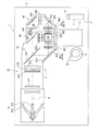
図1は、本実施形態におけるプロジェクター1の概略構成を示す図である。
図1は、プロジェクター1の概略構成を模式的に示す図である。
なお、以下では、プロジェクター1において投射側(投射レンズ3が配置された側)を「前面」とし、その反対側を「背面」とする。また、図1における図面視手前を天面側、奥側を底面側とする。さらに、以下で記載する「左」、「右」は、プロジェクター1を天面が上側となるようにして、前面から見た時の左右に相当するものである。
プロジェクター1は、外部機器等から入力される画像情報に応じて光を変調してスクリーン(図示略)上に投射し、投影画像を表示する。このプロジェクター1は、図1に示すように、略直方体状の外装筐体2と、投射レンズ3と、光学ユニット4と、プロジェクター1内部の各構成部材を冷却する冷却装置5と、具体的な図示を省略したが、プロジェクター1内部の各構成部材に電力を供給する電源ユニット、及びプロジェクター1内部の各構成部材を制御する制御装置等とを備える。
Hereinafter, an embodiment of the present invention will be described with reference to the drawings.
[Projector configuration]
FIG. 1 is a diagram illustrating a schematic configuration of a projector 1 according to the present embodiment.
FIG. 1 is a diagram schematically illustrating a schematic configuration of the projector 1.
Hereinafter, in the projector 1, the projection side (side on which the projection lens 3 is disposed) is referred to as “front surface”, and the opposite side is referred to as “back surface”. Also, the front side of the drawing in FIG. 1 is the top side, and the back side is the bottom side. Furthermore, “Left” and “Right” described below correspond to the left and right when the projector 1 is viewed from the front with the top surface facing up.
The projector 1 modulates light according to image information input from an external device or the like, projects the light onto a screen (not shown), and displays a projected image. As shown in FIG. 1, the projector 1 includes a substantially rectangular parallelepiped outer casing 2, a projection lens 3, an optical unit 4, a
[光学ユニットの構成]
光学ユニット4は、外装筐体2の背面に沿って左側から右側に延出し、延出方向先端部分が前面側に屈曲して延出する平面視略L字形状を有している。
この光学ユニット4は、図1に示すように、光源ランプ411およびリフレクター412を有する光源装置41と、レンズアレイ421,422、偏光変換素子423、および重畳レンズ424を有する照明光学装置42と、ダイクロイックミラー431,432、および反射ミラー433を有する色分離光学装置43と、入射側レンズ441、リレーレンズ443、および反射ミラー442,444を有するリレー光学装置44と、冷却対象としての3つの光変調装置451(赤色光側の光変調装置を451R、緑色光側の光変調装置を451G、青色光側の光変調装置を451Bとする)、3つの入射側偏光板452、3つの出射側偏光板453、およびクロスダイクロイックプリズム454を有する光学装置45と、光学部品用筐体46とを備える。
[Configuration of optical unit]
The optical unit 4 has a substantially L shape in plan view that extends from the left side to the right side along the back surface of the exterior housing 2, and the front end portion in the extending direction is bent and extended to the front surface side.
As shown in FIG. 1, the optical unit 4 includes a
そして、光学ユニット4では、上述した構成により、光源装置41から出射され照明光学装置42を介した光束は、色分離光学装置43にてR,G,Bの3つの色光に分離される。また、分離された各色光は、各光変調装置451にて画像情報に応じてそれぞれ変調され、クロスダイクロイックプリズム454にて合成され、投射レンズ3にてスクリーン(図示略)に拡大投射される。
なお、上述した各光学部品41〜46については、種々の一般的なプロジェクターの光学系として利用されているため、具体的な説明を省略する。
In the optical unit 4, the light beam emitted from the
In addition, about each optical component 41-46 mentioned above, since it is utilized as an optical system of various general projectors, concrete description is abbreviate | omitted.
[冷却装置の構成]
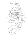
図2は、本実施形態の要部を示す斜視図であり、具体的には、冷却装置5に光学装置45が配置された状態を背面側から見た斜視図である。なお、図示の都合上、入射側偏光板452及び出射側偏光板453の図示を省略する。これは、以下の図でも同様である。
冷却装置5は、冷却対象である光変調装置451、入射側偏光板452(図1参照)、及び出射側偏光板453(図1参照)等に対して冷却空気を送風するものであり、図2に示すように、ダクト6と、冷却ファンとしての第1冷却ファン7と、第2冷却ファン8とを備えている。
[Configuration of cooling device]
FIG. 2 is a perspective view showing a main part of the present embodiment. Specifically, FIG. 2 is a perspective view of the state in which the
The
[ダクトの構成]
ダクト6は、一端側から背面側に延出した後、当該延出する方向に対して直交する方向に曲げられて背面側に沿って延出し、さらに前記延出方向と略平行となる方向へ曲げられて前面側に延出する平面視略コ字状に形成される。このダクト6は、ダクトとしての第1ダクト部61及び第2ダクト部62と、第1ダクト部61の背面側に沿って延出する部分の外側に位置する第3ダクト部63とで一体形成されている。
なお、第1ダクト部61、第2ダクト部62、及び第3ダクト部63の詳細な構成については、後述する。
[Duct structure]
After the
In addition, the detailed structure of the
[冷却ファンの構成]
第1冷却ファン7は、図1に示すように、投射レンズ3の右側面側に配設され、第2冷却ファン8は、図1に示すように、投射レンズ3の左側面側に配設され、各冷却ファン7,8は、本実施形態では、シロッコファンで構成される。
第1、第2冷却ファン7,8は、空気を吸入する吸入口(図示略)と、空気を吐出する吐出口71,81とを備えている。
各冷却ファン7,8の吸入口は、外装筐体2に形成された吸気口(図示略)に対向するように配置され、プロジェクター1の外部の空気が吸気口から各冷却ファン7,8の吸入口に吸入される。
図2に示すように、第1冷却ファン7の吐出口71は、第1ダクト部61の一端側に接続され、第2冷却ファン8の吐出口81は、第2ダクト部61の一端側に接続される。
[Cooling fan configuration]
The
The first and
The suction ports of the cooling
As shown in FIG. 2, the
図3は、冷却装置5の平面図であり、具体的には、冷却装置5に光学装置45が配置された状態を天面側から見た平面図である。図3中の破線矢印は、冷却空気の流れ方向を示している。
第1冷却ファン7は、図3に示すように、外部の空気を吸入し、冷却空気A1として冷却対象である緑色光側の光変調装置451G、赤色光側の光変調装置451R、入射側偏光板452、及び出射側偏光板453に対して第1ダクト部61を介して吐出する。
第2冷却ファン8も同様に、図3に示すように、吸気口から外部の空気を吸入し、冷却空気B1として冷却対象である緑色光側の光変調装置451G、青色光側の光変調装置451B、入射側偏光板452、及び出射側偏光板453に対して第2ダクト部62を介して吐出する。
FIG. 3 is a plan view of the
As shown in FIG. 3, the
Similarly, as shown in FIG. 3, the
[第1ダクト部及び第2ダクト部の構成]
第1ダクト部61及び第2ダクト部62は、第1冷却ファン7から吐出される冷却空気A1、及び第2冷却ファン8から吐出される冷却空気B1を互いに異なる方向から各光変調装置451、入射側偏光板452、及び出射側偏光板453の配設位置近傍まで導く。
第1ダクト部61の他端側には、矩形状の赤側冷却用流出口60Rが天面側に形成され、第2ダクト部62の他端側には、矩形状の青側冷却用流出口60Bが天面側に形成される。また、各ダクト部61,62の他端側において、各ダクト部61,62が互いに連通する位置、すなわち緑色光側の光変調装置451Gの配設位置近傍には、図2及び図3に示すように、矩形状の流出口としての緑側冷却用流出口60Gが天面側に形成される。
また、各ダクト部61,62は、緑側冷却用流出口60Gの位置において、直線状に連通するように形成されている。
各冷却ファン7,8から吐出された冷却空気A1,B1は、これらの流出口60G,60R,60Bから流出し、各光変調装置451、入射側偏光板452、及び出射側偏光板453を冷却する。
各流出口60G,60R,60Bには、天面側において各流出口60G,60R,60Bを囲い、天面側に向けて突出した整流リブ600が形成される。この整流リブ600は、冷却空気A1,B1が冷却対象に対して、下方から上方に向かう流れ方向の整流効果を高めるものである。
[Configuration of first duct portion and second duct portion]
The
A rectangular
Further, the
The cooling air A1 and B1 discharged from the cooling
Each
図4は、図3におけるIV−IV線で切断したダクト6の断面図である。図4中の実線矢印は、冷却空気の流れ方向を示している。
また、第1ダクト部61及び第2ダクト部62は、図3及び図4に示すように、第1整流板64と、第2整流板65と、傾斜部66とを備える。
4 is a cross-sectional view of the
Moreover, the
第1整流板64は、第1ダクト部61及び第2ダクト部62の形状に応じて湾曲形成され、第1ダクト部61の一端側(第1冷却ファン7側)の屈曲する部分から背面側に沿って延出し、第2ダクト部62の一端側(第2冷却ファン8側)の屈曲する部分まで配設される。そして、第1整流板64は、第1冷却ファン7から吐出される冷却空気A1を冷却空気A2,A3に分流するとともに、第2冷却ファン8から吐出される冷却空気B1を冷却空気B2,B3に分流する。
The
冷却空気A2及び冷却空気B2は、第1ダクト部61及び第2ダクト部62をそれぞれ辿って、緑側冷却用流出口60Gに向かう。そして、冷却空気A2及び冷却空気B2は、各ダクト部61,62の連通位置、すなわち緑側冷却用流出口60Gの位置で互いに対向する向きで衝突し、緑側冷却用流出口60Gから緑色光側の光変調装置451G、入射側偏光板452、及び出射側偏光板453に対して下方から上方に向けて流出する。この冷却空気A2,B2は、互いに緑側冷却用流出口60Gの位置で衝突するように、各冷却ファン7,8の冷却空気A1,B1の吐出量が設定され、具体的には、緑側冷却用流出口60Gに導かれる各冷却空気A2,B2の流量が等しくなるように設定されている。本実施形態では、第1冷却ファン7の冷却空気A1の吐出量が、第2冷却ファン8の冷却空気B1の吐出量よりも多くなるように設定されている。これは、第1冷却ファン7から吐出される冷却空気A1の一部は、後述する第3ダクト部63にも導かれるためである。
The cooling air A2 and the cooling air B2 follow the
冷却空気A3は、第1ダクト部61を辿って、赤側冷却用流出口60Rに向かい、赤側冷却用流出口60Rから赤色光側の光変調装置451R、入射側偏光板452、及び出射側偏光板453に向けて流出する。
冷却空気B3は、第2ダクト部62を辿って、青側冷却用流出口60Bに向かい、青側冷却用流出口60Bから青色光側の光変調装置451B、入射側偏光板452、及び出射側偏光板453に向けて流出する。
The cooling air A3 follows the
The cooling air B3 follows the
第2整流板65は、図3及び図4に示すように、緑色光側の光変調装置451Gへの入射光束に対して略直交する方向に、緑側冷却用流出口60Gを跨ぐように、赤側冷却用流出口60Rから青側冷却用流出口60Bまでの位置に配設されている。これにより、第2整流板65は、冷却空気A2をさらに、冷却空気A21,A22に分流するとともに、冷却空気B2をさらに、冷却空気B21,B22に分流する。
As shown in FIG. 3 and FIG. 4, the
冷却空気A21,B21は、緑側冷却用流出口60Gの入射側(緑色光側の光変調装置451Gへの入射光束の光路前段側)に向かい、入射側偏光板452及び緑色光側の光変調装置451Gの光入射面を冷却する。
冷却空気A22,B22は、緑側冷却用流出口60Gの出射側(緑色光側の光変調装置451Gへの入射光束の光路後段側)に向かい、緑色光側の光変調装置451Gの光出射面及び出射側偏光板453を冷却する。
The cooling air A21, B21 is directed to the incident side of the green-
The cooling air A22, B22 is directed to the emission side of the green-
傾斜部66は、図3及び図4に示すように、第1ダクト部61及び第2ダクト部62において、緑側冷却用流出口60Gを挟む位置、第2整流板65が配設されている範囲に形成されている。この傾斜部66は、前記範囲内において、緑側冷却用流出口60Gに向かうにしたがって、底面から天面に向けて傾斜し、緑側冷却用流出口60Gに対向する部分で平坦となっている。すなわち、第1ダクト部61及び第2ダクト部62の断面積S(冷却空気の流れ方向と直交する面で切断した断面積)は、緑側冷却用流出口60Gに向かうにしたがって、小さくなり、冷却空気A2,B2の流速が速められる。これにより、冷却空気A2,B2は、流速を速めながら傾斜部66の傾斜面を辿り、平坦面で互いに対向する向きで衝突し、緑側冷却用流出口60Gから入射側偏光板452、緑色光側の光変調装置451G、及び出射側偏光板453に対して、下方から上方に流出する。
As shown in FIGS. 3 and 4, the
[第3ダクト部の構成]
第3ダクト部63は、図2及び図3に示すように、第1冷却ファン7から吐出される冷却空気A1の一部である冷却空気A4を取り込んで、当該冷却空気A4を偏光変換素子423に導く。この第3ダクト部63の天面側には、偏光変換素子423に冷却空気A4を流出する矩形状の流出口631が形成されている。
[Configuration of third duct part]
As shown in FIGS. 2 and 3, the
上述した本実施形態のプロジェクター1によれば、以下の効果を奏する。
本実施形態によれば、各冷却ファン7,8から吐出された各冷却空気A2,B2が緑側冷却用流出口60Gの位置で衝突し、互いに衝突した冷却空気A2,B2が緑側冷却用流出口60Gから緑色光側の光変調装置451Gに向けて流出する。これによれば、各冷却ファン7,8から吐出された各冷却空気A2,B2を衝突させることで、流路方向を変えているので、上述した従来のダクトの壁面等に衝突させて流路方向を変える場合に比べて、冷却空気A2,B2の圧力損失を抑制でき、流速の低下を抑制できる。すなわち、各冷却空気A2,B2の衝突後も流速を維持した状態で、冷却空気A2,B2が緑側冷却用流出口60Gから緑色光側の光変調装置451Gへ導かれる。従って、緑色光側の光変調装置451Gに導かれる冷却空気A2,B2の流量が減少することがないので、緑色光側の光変調装置451Gに対して十分な流量の冷却空気A2,B2を導くことができ、緑色光側の光変調装置451Gの冷却効率を向上できる。
According to the projector 1 of this embodiment mentioned above, there exist the following effects.
According to the present embodiment, the cooling air A2 and B2 discharged from the cooling
また、各冷却ファン7,8から吐出された冷却空気A2,B2は、緑側冷却用流出口60Gの位置において、互いに対向する向きで衝突するので、例えば、斜め方向等から互いに衝突する場合と比べて、各冷却空気A2,B2の一部がダクト6の壁面まで流れることがない。従って、衝突後の冷却空気A2,B2が流速を低下させることなく、緑側冷却用流出口60Gから緑色光側の光変調装置451Gに向けて流出するので、緑色光側の光変調装置451Gの冷却効率をより向上できる。
さらに、第1ダクト部61の断面積Sは、緑側冷却用流出口60Gに向かうにしたがって小さくなるので、各冷却ファン7,8から吐出された冷却空気A2,B2の流速は、緑側冷却用流出口60Gに向かうにしたがって速くなる。従って、冷却空気A2,B2の流速が緑側冷却用流出口60Gの位置で高められるので、緑色光側の光変調装置451Gに対して導く冷却空気A2,B2の流量を多くでき、緑色光側の光変調装置451Gの冷却効率をより向上できる。
In addition, the cooling air A2 and B2 discharged from the cooling
Furthermore, since the cross-sectional area S of the
ところで、各冷却ファン7,8から吐出された冷却空気A2,B2が、緑側冷却用流出口60Gの位置において、斜め方向から互いに衝突する場合、衝突後の冷却空気A2,B2が緑側冷却用流出口60Gから緑色光側の光変調装置451Gに対して、下方から上方に向けて流出しないおそれがある。
本実施形態では、各冷却ファン7,8から吐出された冷却空気A2,B2は、緑側冷却用流出口60Gの位置において、互いに対向する向きで衝突するので、衝突後の冷却空気A2,B2が緑側冷却用流出口60Gから緑色光側の光変調装置451Gに対して、下方から上方に向けて流出する。従って、緑色光側の光変調装置451Gの冷却効率をより向上できる。
When the cooling air A2 and B2 discharged from the cooling
In the present embodiment, the cooling air A2 and B2 discharged from the cooling
[実施形態の変形]
なお、本発明は前述の実施形態に限定されるものではなく、本発明の目的を達成できる範囲での変形、改良等は本発明に含まれるものである。
前記実施形態では、2つの冷却ファン7,8により冷却対象を冷却していたが、3つ以上の冷却ファンを用いてもよい。
前記実施形態では、緑側冷却用流出口60Gの位置で冷却空気A2、B2が互いに対向する向きで衝突していたが、対向しない向きで衝突してもよい。
前記実施形態では、傾斜部66を形成することで、第1ダクト部61及び第2ダクト部62の断面積Sを緑側冷却用流出口60Gに向かうにしたがって小さくしていたが、傾斜部66を設けずに、第1ダクト部61及び第2ダクト部62自体の径を小さくして断面積Sを小さくしてもよい。
[Modification of Embodiment]
It should be noted that the present invention is not limited to the above-described embodiments, and modifications, improvements, and the like within the scope that can achieve the object of the present invention are included in the present invention.
In the embodiment, the cooling target is cooled by the two cooling
In the embodiment, the cooling air A2 and B2 collide with each other at the position of the green-
In the embodiment, the
前記実施形態では、光学ユニット4は平面視略L字形状を有した構成としたが、これに限らず、例えば、平面視略U字形状を有した構成を採用してもよい。
前記実施形態では、透過型の液晶パネルを用いていたが、反射型の液晶パネルを用いてもよい。
前記実施形態では、光変調装置として液晶パネルを備えたプロジェクター1を例示したが、入射光束を変調して光学像を形成する光変調装置であれば、他の構成の光変調装置を採用してもよい。例えば、マイクロミラーを用いたデバイスなど、液晶以外の光変調装置を用いたプロジェクターにも、本発明を適用することも可能である。
In the embodiment, the optical unit 4 is configured to have a substantially L shape in plan view. However, the configuration is not limited to this, and for example, a configuration having a substantially U shape in plan view may be employed.
In the embodiment, a transmissive liquid crystal panel is used, but a reflective liquid crystal panel may be used.
In the above-described embodiment, the projector 1 including a liquid crystal panel is exemplified as the light modulation device. However, if the light modulation device forms an optical image by modulating the incident light beam, a light modulation device having another configuration is adopted. Also good. For example, the present invention can be applied to a projector using a light modulation device other than liquid crystal, such as a device using a micromirror.
前記実施形態では、投射面に対する画像光の投射方向と、当該画像光に係る画像の観察方向とが略同じであるフロントタイプのプロジェクター1を例示したが、本発明はこれに限らず、投射方向と観察方向とがそれぞれ反対方向となるリアタイプのプロジェクターにも本発明を適用できる。
光源装置41は、光源ランプ411を備える構成に限らず、LED(Light Emitting Diode)等の固体光源を備える構成としてもよい。
In the embodiment, the front type projector 1 in which the projection direction of the image light with respect to the projection surface and the observation direction of the image related to the image light are substantially the same is illustrated, but the present invention is not limited thereto, and the projection direction is not limited thereto. The present invention can also be applied to a rear type projector in which the observation direction and the observation direction are opposite to each other.
The
本発明は、プレゼンテーションやホームシアターに用いられるプロジェクターに利用できる。 The present invention can be used for projectors used in presentations and home theaters.
1…プロジェクター、5…冷却装置、7…第1冷却ファン(冷却ファン)、8…第2冷却ファン(冷却ファン)、60G…緑側冷却用流出口(流出口)、61…第1ダクト部(ダクト)、62…第2ダクト部(ダクト)、451G…緑色光側の光変調装置(冷却対象)。 DESCRIPTION OF SYMBOLS 1 ... Projector, 5 ... Cooling device, 7 ... 1st cooling fan (cooling fan), 8 ... 2nd cooling fan (cooling fan), 60G ... Outlet (outlet) for green side cooling, 61 ... 1st duct part (Duct), 62 ... 2nd duct part (duct), 451G ... Light modulator on green light side (cooling object).
Claims (6)
一端側が前記第1冷却ファンおよび第2冷却ファンにそれぞれ接続され、前記冷却空気を冷却対象に導く第1ダクトおよび第2ダクトと、
前記冷却対象へ向けて前記冷却空気を流出させる流出口と、を備え、
前記第1ダクトおよび第2ダクトは、
他端側において連通し、
前記流出口を跨ぐように設けられ、前記第1冷却ファンおよび第2冷却ファンからの冷却空気のそれぞれを、前記流出口に向けて分流する整流板を有することを特徴とするプロジェクター。 A first cooling fan and a second cooling fan that discharge cooling air;
One end side is connected to the first cooling fan and the second cooling fan, respectively, and a first duct and a second duct for guiding the cooling air to a cooling target;
An outlet for allowing the cooling air to flow out toward the object to be cooled,
The first duct and the second duct are:
Communicating at the other end,
Projector, wherein the provided so as to straddle the outlet, each of the cooling air from the first cooling fan and the second cooling fan, to have a rectifying plate to divert toward the outlet.
前記第1ダクトおよび第2ダクトを前記冷却空気の流通方向と直交する面で切断した断面積は、前記流出口側に小さくなっていることを特徴とするプロジェクター。 The projector according to claim 1,
The cross-sectional area which cut | disconnected the said 1st duct and the 2nd duct by the surface orthogonal to the distribution direction of the said cooling air is small in the said outflow port side.
前記第1ダクトおよび前記第2ダクトは、前記第1冷却ファンからの冷却空気と前記第2冷却ファンからの冷却空気とが衝突する前の位置に、前記流出口側に向かって傾斜する傾斜部を有することを特徴とするプロジェクター。 The projector according to claim 2,
The first duct and the second duct are inclined portions that are inclined toward the outlet side at positions before the cooling air from the first cooling fan and the cooling air from the second cooling fan collide with each other. A projector comprising:
前記第1ダクトおよび前記第2ダクトは、前記流出口が設けられた位置において、直線状に形成されていることを特徴とするプロジェクター。 It is a projector as described in any one of Claims 1-3, Comprising:
The projector according to claim 1, wherein the first duct and the second duct are formed in a straight line at a position where the outflow port is provided.
第1色光を画像情報に応じて変調する第1光変調装置と、
第2色光を画像情報に応じて変調する第2光変調装置と、
第3色光を画像情報に応じて変調する第3光変調装置と、を備え、
前記第1ダクトおよび前記第2ダクトは、
前記第1ダクトの上流側に、前記第1光変調装置に向けて前記冷却空気を流出させる第1流出口と、
前記第2ダクトの上流側に、前記第2光変調装置に向けて前記冷却空気を流出させる第2流出口と、
前記第1ダクトおよび前記第2ダクトの下流側に、前記第1冷却ファンからの冷却空気と前記第2冷却ファンからの冷却空気とを衝突させた冷却空気を前記第3光変調装置に向けて流出させる第3流出口と、を有することを特徴とするプロジェクター。 The projector according to any one of claims 1 to 4, wherein:
A first light modulation device for modulating the first color light according to image information;
A second light modulation device for modulating the second color light according to the image information;
A third light modulation device for modulating the third color light according to the image information,
The first duct and the second duct are:
A first outlet through which the cooling air flows out toward the first light modulator on the upstream side of the first duct;
A second outlet for allowing the cooling air to flow toward the second light modulator on the upstream side of the second duct;
Cooling air in which cooling air from the first cooling fan and cooling air from the second cooling fan collide downstream of the first duct and the second duct toward the third light modulation device. A projector having a third outlet for discharging.
前記第1ダクトおよび第2ダクトは、
前記第1ダクトの上流側から前記第2ダクトの上流側に亘って設けられ、前記第1冷却ファンおよび第2冷却ファンからの冷却空気を、前記第1流出口および前記第2流出口へ流通する冷却空気と、前記第3流出口へ流通する冷却空気とに分流する第1整流板と、
前記第1流出口から前記第2流出口までの位置に設けられ、前記第1整流板により分流され第3流出口へ流通する前記第1冷却ファンおよび第2冷却ファンからの冷却空気のそれぞれを、前記第3光変調装置の光入射側と光射出側とに対応するように分流する第2整流板と、を有することを特徴とするプロジェクター。 The projector according to claim 5, wherein
The first duct and the second duct are:
The cooling air is provided from the upstream side of the first duct to the upstream side of the second duct, and the cooling air from the first cooling fan and the second cooling fan is circulated to the first outlet and the second outlet. And a first rectifying plate that divides the cooling air that flows into the third outlet and the cooling air that flows to the third outlet.
Provided at a position from the previous SL first outlet to the second outlet, each of the cooling air from the first cooling fan and the second cooling fan flows into the third outlet being shunted by the first rectifying plate And a second rectifying plate that diverts the light so as to correspond to the light incident side and the light emission side of the third light modulation device.
Priority Applications (3)
| Application Number | Priority Date | Filing Date | Title |
|---|---|---|---|
| JP2010077516A JP5593777B2 (en) | 2010-03-30 | 2010-03-30 | projector |
| US13/049,132 US8696139B2 (en) | 2010-03-30 | 2011-03-16 | Projector having a plurality of cooling fans |
| CN201110081890.XA CN102207666B (en) | 2010-03-30 | 2011-03-29 | Projector |
Applications Claiming Priority (1)
| Application Number | Priority Date | Filing Date | Title |
|---|---|---|---|
| JP2010077516A JP5593777B2 (en) | 2010-03-30 | 2010-03-30 | projector |
Publications (3)
| Publication Number | Publication Date |
|---|---|
| JP2011209533A JP2011209533A (en) | 2011-10-20 |
| JP2011209533A5 JP2011209533A5 (en) | 2013-04-25 |
| JP5593777B2 true JP5593777B2 (en) | 2014-09-24 |
Family
ID=44696573
Family Applications (1)
| Application Number | Title | Priority Date | Filing Date |
|---|---|---|---|
| JP2010077516A Expired - Fee Related JP5593777B2 (en) | 2010-03-30 | 2010-03-30 | projector |
Country Status (3)
| Country | Link |
|---|---|
| US (1) | US8696139B2 (en) |
| JP (1) | JP5593777B2 (en) |
| CN (1) | CN102207666B (en) |
Families Citing this family (5)
| Publication number | Priority date | Publication date | Assignee | Title |
|---|---|---|---|---|
| JP5760345B2 (en) | 2010-08-09 | 2015-08-12 | セイコーエプソン株式会社 | projector |
| JPWO2013069039A1 (en) * | 2011-11-07 | 2015-04-02 | 日立マクセル株式会社 | Projection-type image display device |
| CN106814527B (en) | 2015-10-07 | 2019-04-23 | 精工爱普生株式会社 | Projector |
| CN110780518A (en) * | 2019-09-24 | 2020-02-11 | 深圳市火乐科技发展有限公司 | Projector with a light source |
| CN115096031B (en) * | 2022-05-11 | 2024-01-26 | 北京华卓精科科技股份有限公司 | Silicon wafer bearing device in lithography equipment |
Family Cites Families (14)
| Publication number | Priority date | Publication date | Assignee | Title |
|---|---|---|---|---|
| US6481854B1 (en) * | 1998-12-28 | 2002-11-19 | Fujitsu Limited | Projection type display apparatus having air cooling arrangement |
| JP2000231154A (en) | 1999-02-10 | 2000-08-22 | Hitachi Ltd | Display device and display optical system part |
| TW524317U (en) * | 2001-12-06 | 2003-03-11 | Optoma Coporation | Cooling airway device of opto-mechanical engine illuminating system |
| JP3639271B2 (en) * | 2002-07-30 | 2005-04-20 | 株式会社東芝 | Projection display device and blower |
| JP4093073B2 (en) * | 2003-02-14 | 2008-05-28 | セイコーエプソン株式会社 | projector |
| JP4492168B2 (en) * | 2004-03-23 | 2010-06-30 | セイコーエプソン株式会社 | Optical apparatus and projector |
| JP2005338236A (en) | 2004-05-25 | 2005-12-08 | Seiko Epson Corp | Projector |
| US7393109B2 (en) * | 2004-09-03 | 2008-07-01 | Infocus Corporation | Method and apparatus for cooling optics |
| CN101140411B (en) * | 2006-09-05 | 2010-09-29 | 深圳华强三洋技术设计有限公司 | Projection device |
| JP4967773B2 (en) * | 2007-04-12 | 2012-07-04 | ソニー株式会社 | Projection display |
| JP5455175B2 (en) | 2007-09-19 | 2014-03-26 | Necディスプレイソリューションズ株式会社 | Cooling device, electronic apparatus equipped with cooling device, and liquid crystal projector |
| JP4956837B2 (en) * | 2007-10-05 | 2012-06-20 | Necディスプレイソリューションズ株式会社 | Electronic device cooling apparatus and liquid crystal projector apparatus including the same |
| JP5225759B2 (en) * | 2008-06-09 | 2013-07-03 | 株式会社三社電機製作所 | Equipment cooling device |
| JP2011075763A (en) | 2009-09-30 | 2011-04-14 | Sanyo Electric Co Ltd | Projection type video display device |
-
2010
- 2010-03-30 JP JP2010077516A patent/JP5593777B2/en not_active Expired - Fee Related
-
2011
- 2011-03-16 US US13/049,132 patent/US8696139B2/en active Active
- 2011-03-29 CN CN201110081890.XA patent/CN102207666B/en active Active
Also Published As
| Publication number | Publication date |
|---|---|
| CN102207666B (en) | 2014-01-22 |
| JP2011209533A (en) | 2011-10-20 |
| CN102207666A (en) | 2011-10-05 |
| US20110242500A1 (en) | 2011-10-06 |
| US8696139B2 (en) | 2014-04-15 |
Similar Documents
| Publication | Publication Date | Title |
|---|---|---|
| JP3467697B2 (en) | Cooling device for electro-optical device and projector | |
| US8591037B2 (en) | Projector with a turbo fan rotatable about a vertical axis | |
| JP5593777B2 (en) | projector | |
| KR20110109941A (en) | Projector | |
| JP5381307B2 (en) | projector | |
| US10884328B2 (en) | Projection display apparatus | |
| JP5471708B2 (en) | projector | |
| JP5760345B2 (en) | projector | |
| JP5500231B2 (en) | projector | |
| JP5949962B2 (en) | projector | |
| JP2013145259A (en) | Projector | |
| US11415869B2 (en) | Electronic device and projectors | |
| JP5834779B2 (en) | projector | |
| JP5136367B2 (en) | projector | |
| JP2014085390A (en) | Projector | |
| JP2010262153A (en) | Projector | |
| JP2009210862A (en) | Projector | |
| JP5900008B2 (en) | projector | |
| JP2010113111A (en) | Projector | |
| JP6435677B2 (en) | projector | |
| JP2016145921A (en) | projector | |
| JP2016180838A (en) | projector | |
| JP2023125816A (en) | projector | |
| JP2009210861A (en) | Projector | |
| JP2010262152A (en) | Projector |
Legal Events
| Date | Code | Title | Description |
|---|---|---|---|
| A521 | Request for written amendment filed |
Free format text: JAPANESE INTERMEDIATE CODE: A523 Effective date: 20130308 |
|
| A621 | Written request for application examination |
Free format text: JAPANESE INTERMEDIATE CODE: A621 Effective date: 20130308 |
|
| A977 | Report on retrieval |
Free format text: JAPANESE INTERMEDIATE CODE: A971007 Effective date: 20131003 |
|
| A131 | Notification of reasons for refusal |
Free format text: JAPANESE INTERMEDIATE CODE: A131 Effective date: 20131008 |
|
| A521 | Request for written amendment filed |
Free format text: JAPANESE INTERMEDIATE CODE: A523 Effective date: 20131202 |
|
| A131 | Notification of reasons for refusal |
Free format text: JAPANESE INTERMEDIATE CODE: A131 Effective date: 20140212 |
|
| A521 | Request for written amendment filed |
Free format text: JAPANESE INTERMEDIATE CODE: A523 Effective date: 20140407 |
|
| TRDD | Decision of grant or rejection written | ||
| A01 | Written decision to grant a patent or to grant a registration (utility model) |
Free format text: JAPANESE INTERMEDIATE CODE: A01 Effective date: 20140708 |
|
| A61 | First payment of annual fees (during grant procedure) |
Free format text: JAPANESE INTERMEDIATE CODE: A61 Effective date: 20140721 |
|
| R150 | Certificate of patent or registration of utility model |
Ref document number: 5593777 Country of ref document: JP Free format text: JAPANESE INTERMEDIATE CODE: R150 |
|
| S531 | Written request for registration of change of domicile |
Free format text: JAPANESE INTERMEDIATE CODE: R313531 |
|
| R350 | Written notification of registration of transfer |
Free format text: JAPANESE INTERMEDIATE CODE: R350 |
|
| LAPS | Cancellation because of no payment of annual fees |